

TVT Digital TD-9524S1, TD-9534S1, TD-9514S1L Quick Start Manual
Package
Overview
Installation
1
2
3
4
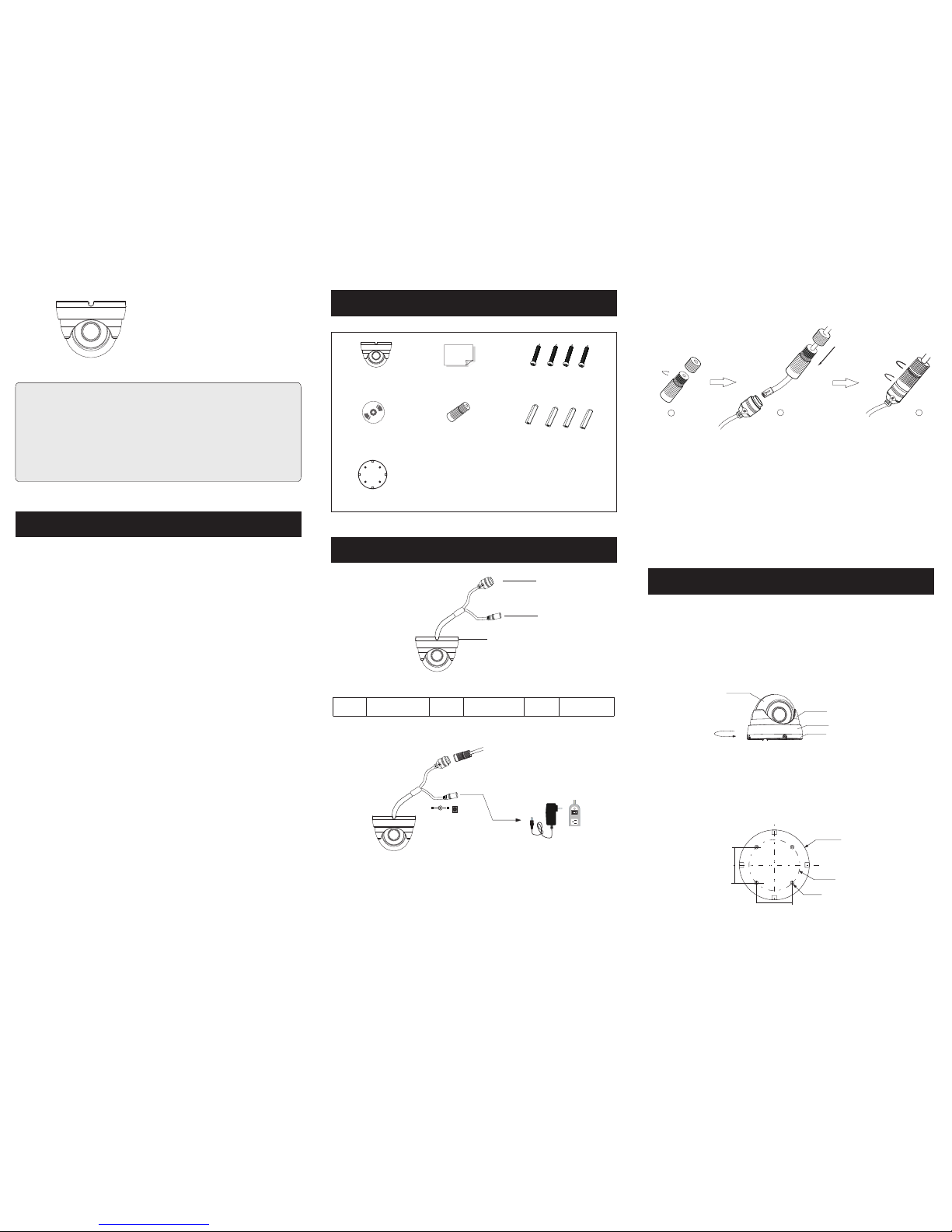
► Connec tin g Net wor k Cab le
2
1
3
* 1 It is recomm ended to ins tall the wat er-proo f cap for netwo rk cable con nectio n.
* 2 If the PoE net work swit ch is used t o conne ct the ca mera th at supp orts th e PoE
pow er suppl y, DC12V p ower sup ply is not r equir ed.
① Loo sen the n ut from t he main e lemen t.
② Run t he netw ork cab le (wit hout RJ 4 5 conne ctor) t hroug h the
bot h eleme nts. Th en crimp th e cable wit h RJ 45 c onne cto r.
③ Con nect th e cable t o the her metic c onnec tor. Th en ti ghte n the
nut a nd the ma in cove r.
Tha nk you fo r purch asing o ur prod uct. Th ere may be se veral
tec hnica lly inc orrec t place s or prin ting er rors in t his man ual.
The u pdate s will be a dded in to the ne w versi on of thi s manua l.
We wil l read ily imp rove or u pdate t he prod ucts or p roc edur es
des cribe d in the ma nual. T he conten t is subjec t to ch ange
wit hout no tice.
Warning and Caution
■ If th e produ ct does n ot work p roper ly, plea se contac t you r deal er
or th e neare st serv ice cen ter. Nev er at temp t to disa ssemb le the
cam era you rself . (We shal l not be r espon sible f or any pr oblem s
cau sed by un autho rized r epair o r maint enanc e.)
■ Kee p away fr om liqu id whil e in use.
■ In th e use of th e produ ct, you m ust be st rict co mplia nce wit h the
ele ctric al safe ty regu latio ns of the n ation a nd regi on. Whe n the
pro duct is m ounte d on wall o r ceili ng, the d evice s hall be f irmly
fix ed.
■ Do no t use cam era bey ond spe cifie d volta ge rang e.
■ Do no t drop th e camer a or subj ect it to p hysic al shoc k.
■ Avoid t ouch ing the c amera l ens.
■ If cl eanin g is nece ssary, p lease use c lea n clot h to wi pe it ge ntly.
If th e devic e will no t be used f or a long t ime, pl ease co ver the l ens
cap t o prote ct the de vice fr om dirt .
■ Do no t aim the c amera a t the sun o r extra b right p lace.
■ Do not place the camera in extremely hot, cold (the opera ting
temper ature shall be -20˚ C~50˚C) , dusty or damp locatio ns, and do
not expos e it to high elect romagne tism radiat ion.
■ To avo id heat acc umulati on, good ve nti lati on is r equi red for
ope ratin g envir onmen t.
■ A few pa rts o f the de vice sh all be re place d regul arly ac cordi ng
to th eir ave rage en durin g time. R egula r check ing is re comme nded
for a ll user s.
Quick Star t Guide
Network Camera
Cam era
Qui ck star t guide
CD
Water -pro of cap
Pla stic pl ug ×4
Dri ll temp late
4 tap ping sc rews PA 4×25
Ple ase mak e sure th at the wa ll or cei ling is s trong e nough t o
wit hstan d 3 times t he weig ht of the c amera .
①
disas semble the came ra from the mountin g base.
Rotate the fix ed ring of the camera in anti-c lockwis e direction to
② Attach the drill template to the place where you want to fix the camera
and then drill 4 screw holes and 1 cable hole ( if you want to route the
cables through the mounting base ) according to the drill template.
∅5
∅68 .2
∅94
48. 1mm
48. 1mm
Dom e
Enc losur e
Fix ed Ring
Mou nting B ase
N
e
twor k C
ab
l
e
DC12V
1
2
3
3
1
2
Net work Ca ble
Mou nting B ase
Pow er Cabl e
IE Network Connection
5
MENU
MENU
IPC
IPC
N etwor k Cab le N etwor k Cab le
N etwor k Cab le
Swi tch
Rou ter
Com puter
Com puter
● Access t he ca mer a through IP- Tool
Her e we take a ccess ing IP camera v ia LA N for ex amp le. In L AN,
the re are tw o ways to a ccess . 1. Access t hro ugh IP -Tool;
2. Di rectl y Access th rou gh IE Br ows er
① Make sure that the camer a and the PC are well connected via LAN.
② Fin d the IP- Tool f rom the C D and the n insta ll it in th e com pute r.
Afte r that, r un th e IP-To ol as shown b elow.
Devi ce Netw ork Sea rch
Imme diate R efres h
name
name
name
IPC
IPC
IPC
unkno wn
unkno wn
unkno wn
192.1 68.22 6.201
192.1 68.1. 2
192.1 68.1. 3
80
80
80
9008
9008
9008
255.2 55.
255.2 55.
255.2 55.
Modif y Netwo rk Para meter
Mac Addr ess
IP Addre ss
Modif y
CE :98 :2 3 :75 :35 : 22
192 .16 8 . 226 . 201
255 . 255 . 2 55 . 0
192 .16 8 . 226 . 1
i
Tip: Ent er the ad minis trato r passw ord, and
then mo dify th e netwo rk para meter s.
Total Dev ice: 3
Local I P Addres s:192 .168. 1.4
Subne t Mask: 255.2 55.25 5.0 Gatew ay: 192 .168. 1.1 DN S:210.2 1.196 .6
Devic e Name Devic e Type IP Addre ss Http Po rt Data Po rt
Subne t
Produ ct Mode l
Abou t
Subne t Mask
Gatew ay
Restore IPC Default Configuration
③ Mod ify the I P add ress. The d efau lt IP ad dress of th is camera i s
192 .168. 226.2 01. Cli ck the in forma tion of t he came ra list ed in the
abo ve tabl e to show t he netw ork inf ormat ion on th e right h and.
Mod ify the I P add ress and ga teway of th e cam era an d mak e sure i ts
net work ad dress i s in the sa me loca l netwo rk segm ent as th at of the
com puter. P lea se mod ify the I P add ress o f your de vice ac cordi ng
to th e pract ical si tuati on.
Mac Add ress
IP Addr ess
Modi fy Netw ork Par amete r
Modi fy
CE :98 : 23 :75 :3 5 :22
192 . 168 . 1 . 201
255 . 25 5 . 255 . 0
192 . 168 . 1 . 1
Subn et Mask
Gate way
For e xampl e, the IP addre ss of y our co mpu ter is 1 92.16 8.1.4 . So the
IP address of the camera shall be changed to 192.168. 1.X. After
modif ication , pleas e input th e passw ord of the admini strat or and cli ck
“Mod ify” bu tton t o modi fy th e sett ing.
The d efault pa ssword of t he ad mini str ator i s “1234 56” .
④ Double-cl ick the IP address and then the system will pop up the IE
browser to connect IP-CAM. After downl oading Act ive X co ntrol , a
login window will pop up. Input the user name and password to login.
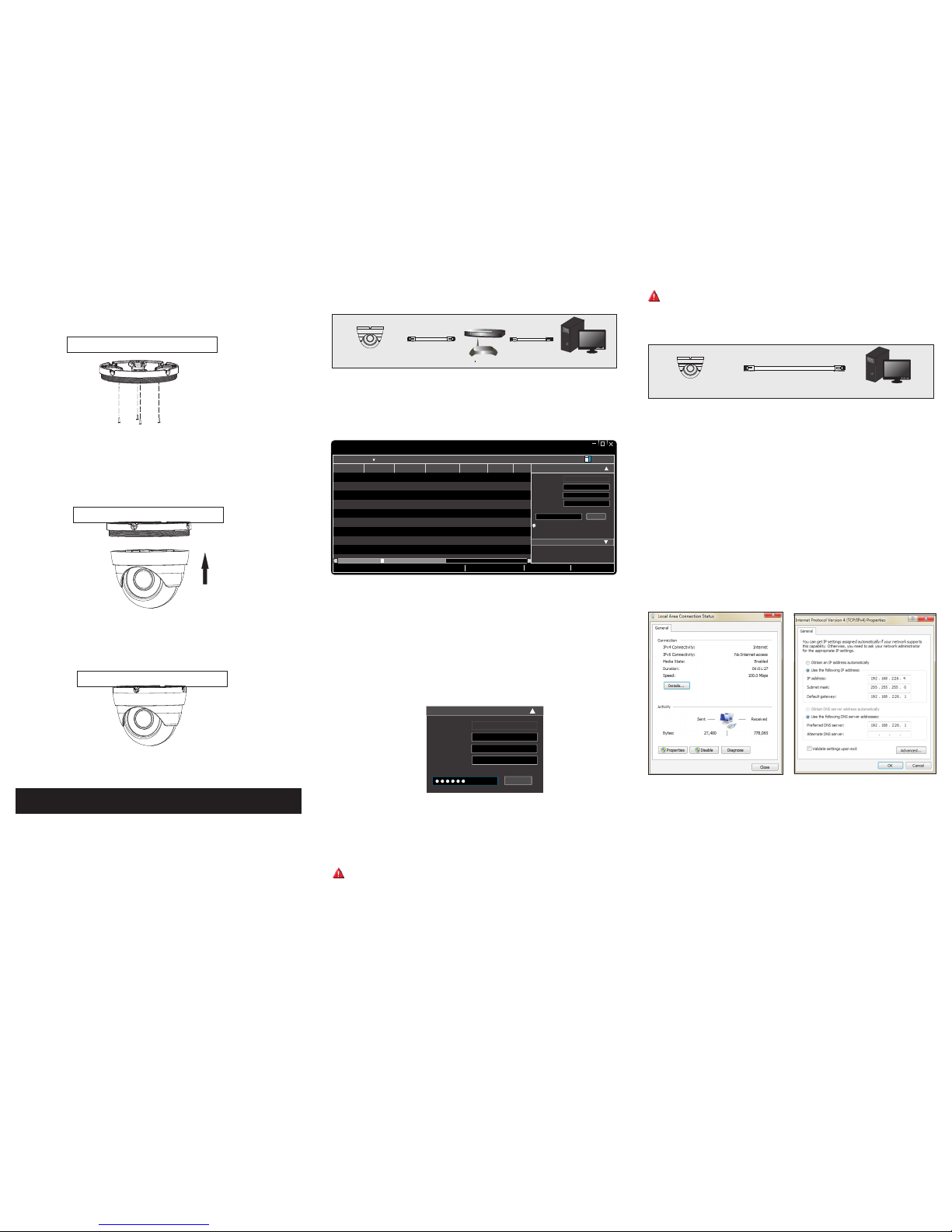
● Direct ly Acc ess Th rou gh IE
The d efaul t netwo rk sett ings ar e as show n below :
IP addres s: 19 2.16 8.2 26.2 01 HTTP :80
Sub net Mas k: 255. 255.2 55.0 Da ta Port :9008
Gat eway: 1 92.16 8.226 .1
You may use th e above de fault s ettin gs when yo u log in the ca mera
for th e firs t time.
① Set t he IP address o f the P C and ma ke su re the n etwor k segme nt
should be as the sa me as the de fault se ttin gs of IP-C AM. Open the
network an d share c enter. C lick “L ocal Are a Con nect ion ” to pop u p
the f ollow ing win dow. Sel ect “Prop ert ies” a nd th en sel ect Int ernet
pro tocol a ccord ing to th e actua l situa tion (f or exam ple: IP v4).
Nex t, clic k “Prop ertie s” butt on to set t he netw ork of th e PC.
② Ope n the IE br owser a nd inpu t the def ault ad dress o f IP-CA M
and c onfir m. The IE b rowser wi ll downlo ad Active X co ntr ol
aut omati cally.
③ Aft er down loadi ng Active X c ont rol, t he lo gin di alog bo x will
pop u p.
④ Inp ut the de fault u serna me and pa sswor d and the n enter t o view.
450 04300 0480 A0
The d efault us ername is a dmi n; the d efa ult pa sswor d is 1234 56.
⑤ The installation is complete as shown below.
③
base to the ceiling or wall with screws.
then secure the mounting Route the cables and connect the cables. And
④ Adjust the camera to obtain an optimum angle. Then secure the camera
to the mounting base.
Ceiling or Wall
 Loading...