

TVT Digital TD-9483S3 Quick Start Manual
Network Camera
● Connecting Alarm In pu t/ Ou tp ut
Alarm Input
Quick Star t Guide
■ Please read this ins tr uc ti on c ar efully before using the produ ct a nd
keep it for furthe r re fe re nc e.
■ All the examples and p ic tu re s us ed h ere are for reference only.
■ The contents of th is m an ua l ar e su bj ect to change without notice.
Warning and Caution
1
■ If the product doe s no t wo rk p ro pe rl y, pl ea se c on ta ct your dealer or the
nearest servic e ce nt er. N ev er a tt em pt t o disassemble the camera your se lf .
(We sh al l no t be r es ponsible for any problems cau se d by u na ut ho ri zed repair
or maintenance .)
■ Do not allow water o r li qu id i nt ru si on into the camera.
■ In the use of the pr oduct, you mu st be st rict complian ce with the electrica l
safety regu lations of the nation and region. When the product is mounted on
wall, the device s ha ll b e fi rm ly f ix ed.
■ Do not use camera beyo nd s pe ci fi ed v oltage range.
■ Do not drop the came ra o r su bj ec t it t o ph ysical shock.
■ Avoid t ou ch in g th e camera lens.
■ If cleaning is neces sa ry, pleas e us e cl ea n cl ot h to w ipe it gently. If t he
device will not be u se d fo r a lo ng t im e, p lease cover the lens cap to protect
the device from di rt .
■ Do not aim the camera at t he s un o r ex tr a br ight place.
■ Do not place the camera in extremely hot, cold (the operating temperature shall
be -30˚C~60˚C), dusty or damp locations, and do not expose it to high
electromagnetic radiation.
■ To avo id h eat accumulation, good vent il at io n is r eq ui red for operating
environment.
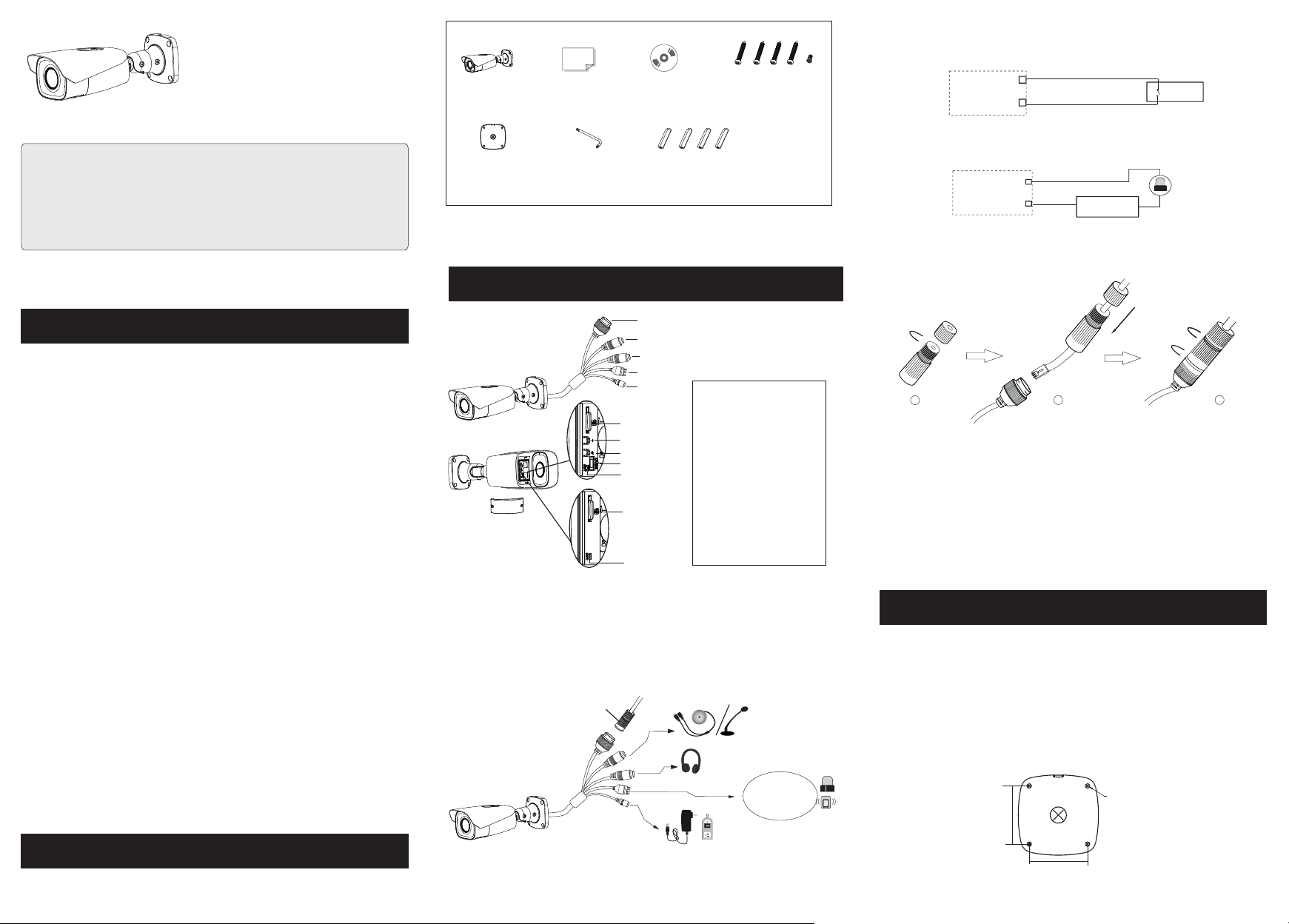
Camer a
Drill t em pl ate
Overview
3
Quick s ta rt g uide
Screw dr iv er
CD
Plast ic p lu g × 4
4 tapping screws
1 machine screw
1
2
3
RM
A
L
A
4 3 2 1
4
5
6
7
(Typ e A)
8
9
10
6
(Typ e B)
10
If th e PoE swi tch is us ed to pow er the ca mera, D C12V po wer sup ply is no t requi red.
*
* Onl y some mo dels su pport T &W bu tto ns. If yo ur came ra does n’t hav e the se two bu ttons , pleas e
ski p 7 and 8.
ty ca p
i
cur
Se
RM
A
AL
4 3 2 1
1 Eth ernet C onnec tor
2 MIC -Audi o Input
3 HP- Audio O utput
4 Alar m Outpu t/Inp ut
5 Pow er Conn ector *
6 Mic ro SD Car d Slot
7 Zoo m +*
8 Zoo m -*
9 CVBS ou tput (una vai labl e)
10 Re set
1-- ALM-C OM
2-- ALM-O PEN
3-- ALM-I NA
4-- ALM-G ND
IPC
ALA RM-IN A
ALA RM-GN D
3
4
Senso r
Alarm Ouput
ALA RM1/2 -COM
IPC
ALA RM1/2 -OPEN
● Connecting N et wo rk C ab le
1
+
2
Pow er Sour ce
+
Ala rm
-
-
3
① Loosen the nut fro m th e ma in e le me nt .
② Run the network ca bl e (w it ho ut R J 45 c onnector) through the both
elements. Then crimp the cable with RJ 4 5 co nn ec to r.
③ Connect the cable to t he h er me ti c co nn ector. Then tighten the nut and
the main cover.
Installation
4
Please make sure t ha t th e wa ll o r ce il ing is strong enough to withsta nd 3
times the weight o f th e ca me ra . Please install the camera under dry
environment.
① Attach the drill template to the place where you want to fix the camera. Then
dri ll t he s cr ew holes and the cable hole on the wa ll a cc or di ng t o th e drill
template.
∅5
64.6mm
Package
2
DC1 2V
64.6mm
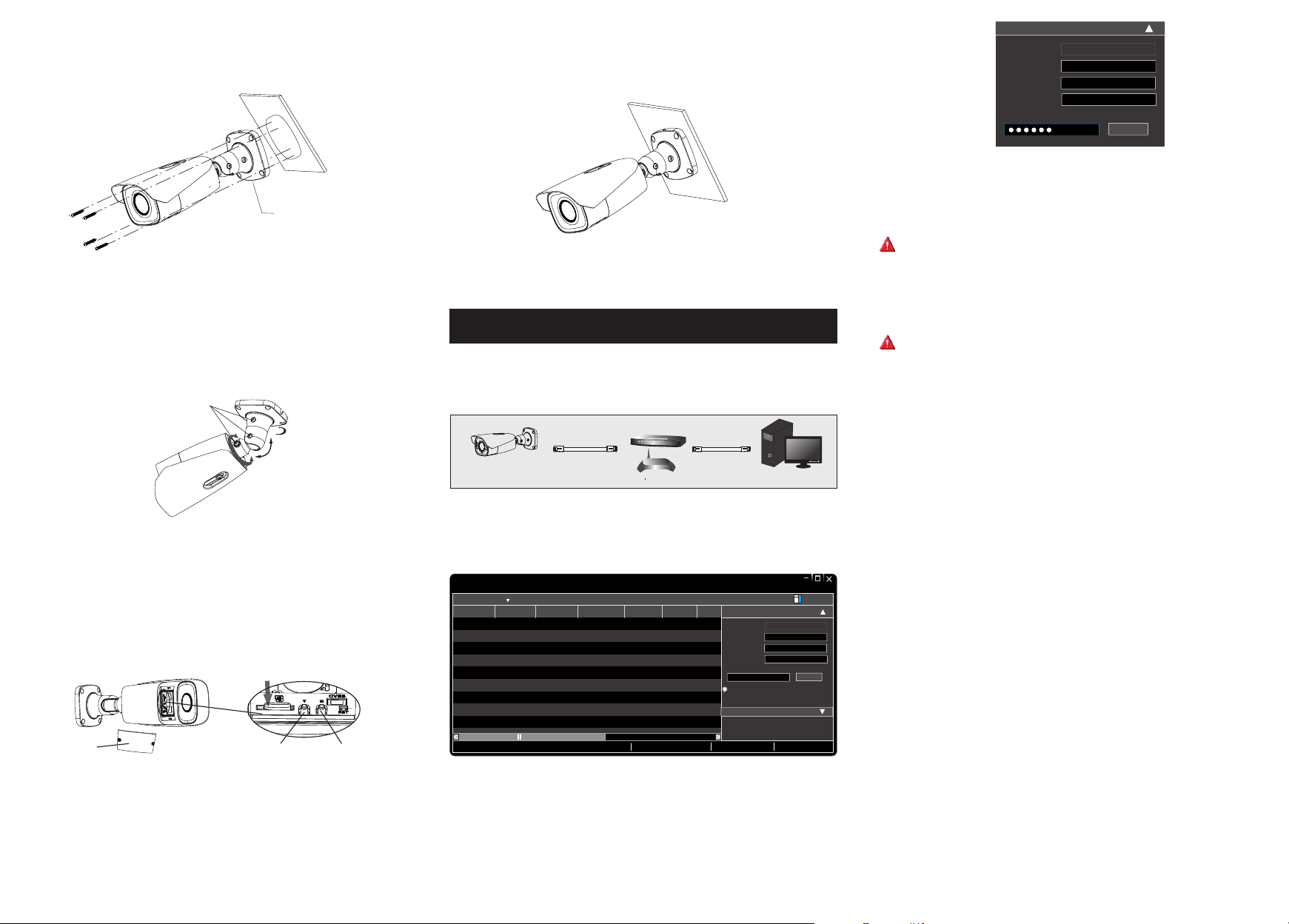
② Route the cables a nd c on ne ct t he r el evant cables.
③ Fasten the mount in g ba se t o th e wa ll w ith the screws provided.
Mou nt in g Bas e
④ Bracket adjustment. Before adjustment, preview the image of the
camera on a
monitor and then lo osen the fixe d screws to adjust th e view angle of the camera.
After that, tigh te n th e fi xe d sc re ws.
Fixed Scr ew s
Pan 360°
Tilt 90°
Rotate
360°
⑦
Install the cove r ba ck t o th e ca me ra a nd fix it firmly with the screws. (No te
that the cover sho ul d no t be i ns ta ll ed unevenly.
Network Connection
5
)
● Access the cam era through IP- Tool
Switc h
IPC
Net work Cabl e Net work Cabl e
Route r
Compu te r
Mod ify Net work Pa ramet er
Mac Ad dress
IP Add re ss
Sub net Mas k
Gat ew ay
CE :9 8 :23 :75 : 35 : 22
192 .16 8 . 1 . 20 1
255 . 255 . 2 55 . 0
192 .16 8 . 1 . 1
Mod ify
For ex amp le, the IP addr ess of your co mputer is 192. 168 .1. 4. So th e IP address of the
camera shall be changed to 192.168.1.X and the gat eway shall be changed to 192 .1 68 .1.1.
After modification, ple ase enter the pas sword of th e administrator and cli ck “Modify”
button t o mo dify th e se tt ings.
The d ef ault pass wo rd o f the adm in is trator is “ 12 34 56 ”.
④ Double-click the camera listed in the IP-Tool or manuall y enter the IP address in the
addres s bar o f th e we b browser t o co nn ect IP- CA M. Then f ol lo w directi on s to
downl oa d an d install t he p lugin.
⑤ Enter t he u se rname a nd p as sword in th e lo gi n interfa ce .
The d ef ault user na me i s ad min ; th e de fault pas sw or d is 1 23 456 .
MENU
Open the cover of th e ca me ra a s sh ow n in t he following figure and then
⑤
insert a micro SD ca rd .
Press T/W but to n to o bt ain an optimum image. Before adju st me nt , vi ew
⑥
the image of the camer a on a m on it or.
Ins ert a mic ro
SD ca rd
Cov er
Note: O nl y so me mode ls s up port T& W butto ns . If y our camer a do es n’t h av e th ese two
butto ns , pl ease skip s te p ⑥ .
Zoo m+
Zoo m-
① Make sure that the camera and the PC are well con nected via LAN.
② Find th e IP -Tool fr om t he C D and the n in st all it in the c om pu ter. Afte r th at, run the
IP-Too l as shown be lo w.
Dev ice Net work Se arch
Imm ediat e Refre sh
Devi ce Name Devi ce Type IP Addr ess Http P ort Data P ort
name
name
name
Total De vice: 3
IPC
IPC
IPC
Prod uct Mod el
unkn own
192. 168.2 26.20 1
unkn own
192. 168.1 .2
unkn own
192. 168.1 .3
Loca l IP Addre ss:19 2.168 .1.4
80
9008
80
9008
80
9008
Subn et Mask :255. 255.2 55.0 Gate way: 19 2.168 .1.1 DNS:21 0.21 .196. 6
Subn et
Modi fy Netw ork Par amete r
255. 255.
Mac Add ress
255. 255.
IP Addr ess
Subn et Mask
255. 255.
Gate way
i
Tip: E nter th e admin istra tor pas sword, and
then m odify t he netw ork par amete rs.
Restore IPC Default Configuration
Abo ut
CE :98 : 23 :75 :3 5 :22
192 . 168 . 226 . 20 1
255 . 25 5 . 255 . 0
192 . 168 . 226 . 1
Modi fy
③ Modif y th e IP ad dr ess. Th e de fault IP addre ss o f th is came ra i s 19 2.168.2 26 .2 01.
Click t he i nf ormat io n of t he camera l is te d in the abov e ta ble to show t he n et work
infor ma ti on on the r ig ht h and. Modi fy t he I P add ress and ga te wa y of the ca me ra a nd
make su re i ts n etwork ad dr ess is in the s am e lo cal netwo rk s eg ment as t he c om puter’s .
Pleas e mo di fy the IP addres s of y ou r devic e ac co rding to th e pr ac tical s it ua tion.
450043001393 A0
 Loading...