

TVT Digital TD-9452A3-PA Quick Start Manual
Network Camera
* 1 It is recommended to inst all th e security cap fo r outdoor instal la ti on.
* 2 If the Po E sw it ch is used to p ow er th e ca me ra, DC12V p ow er supp ly i s no t
req ui red .
Quick Star t Guide
■ Please read thi s instruc tion carefully b efore ope ratin g the unit
and keep it for fur ther refe rence .
■ All the example s and pictu res used here are fo r referen ce only.
■ The contents of t his manua l are subject to cha nge witho ut
notice.
Warning and Caution
1
■ If the product do es not work p roper ly, please con tact your d ealer
or the nearest se rvice cen ter. Never a ttempt to disass emble the
camera yourse lf. (We shall not be r esponsible for a ny proble ms
caused by unaut horized r epair o r mainten ance.)
■ In the use of the pro duct, you m ust be st rict comp liance wi th the
electrical sa fety regu lations of the nat ion and reg ion. When the
product is moun ted on wall o r ceili ng, the dev ice shall b e firml y
fixed.
■ Do not allow wate r or liquid i ntrusion into th e camera.
■
Do not use camera b eyond spe cified voltage r ange.
■ Do not drop the cam era or subj ect it to physical s hock.
■ Avoid touching t he camera l ens.
■ If cleaning is ne cessary, ple ase use clean clot h to wipe it ge ntly.
■ Do not aim the came ra at the sun o r extra bright pla ce.
■ Do not place the camera in extremely hot, cold (the operating
temperature shall be -30˚C~60˚C), dusty or damp locations, and do
not expose it to high electromagnetic radiation.
■ To avoid heat a ccumulation, g ood venti lation is requir ed for
operating env ironmen t.
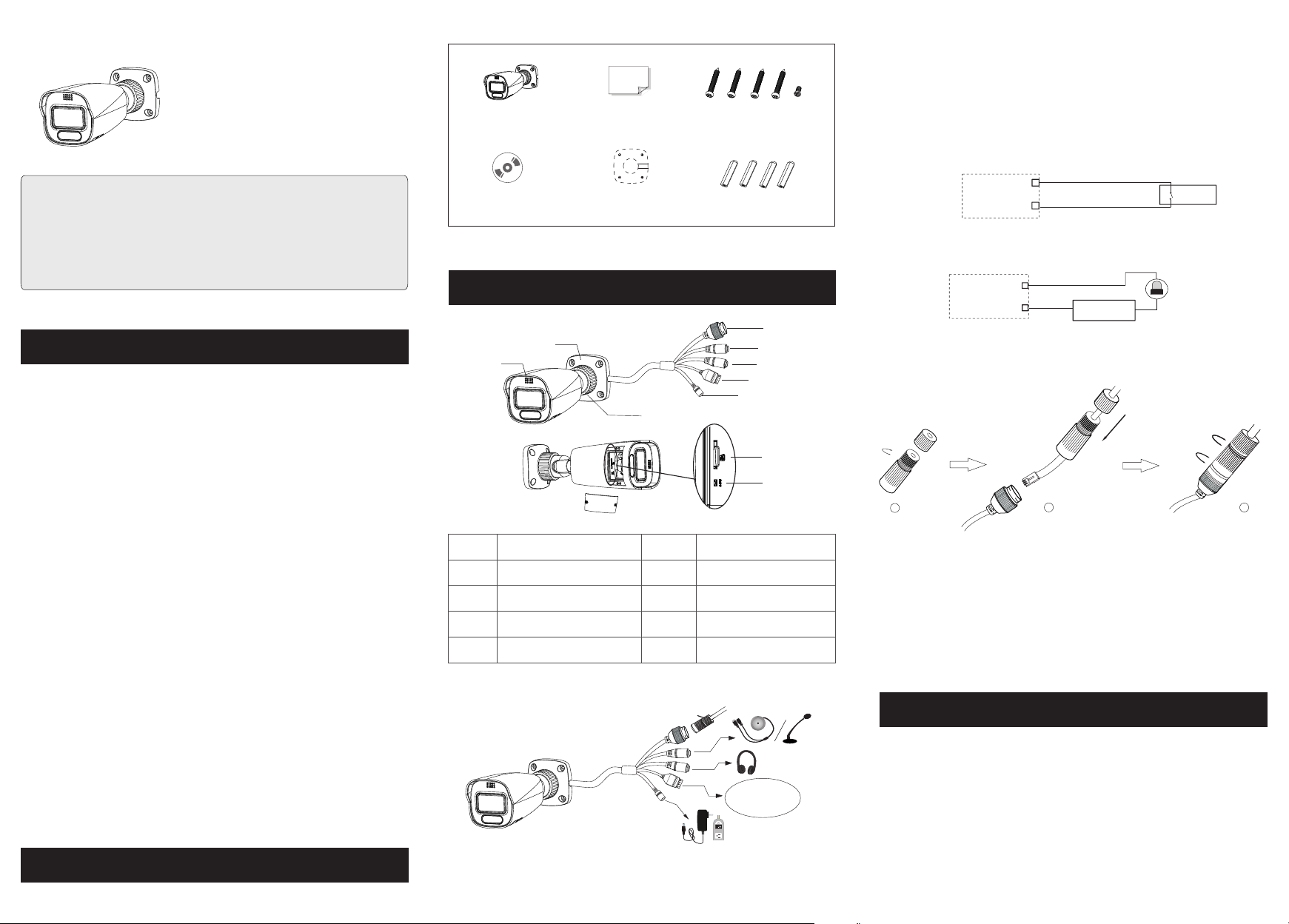
Package
2
Camer a
CD
Overview
3
6
Ethernet connect or
1
2
Audio input conn ec to r
Audio output con ne ct or
3
4
Alarm input/ ou tp ut
5
Power connecto r
Quick s ta rt g uide
4 tapping screws PA 4×2 5
1 machine screw PW M3 ×5
► Connecting A larm Input/Outpu t
Alar m Input:
Drill t em pl ate
Plast ic p lu g × 4
IPC
ALA RM-IN A
ALA RM-GN D
3
4
Senso r
Alar m Output:
IPC
ALA RM-CO M
ALA RM-OP EN
1
2
Power
+
1
7
RM
A
L
A
4 3 2 1
2
3
► Connecting N etwork Cable
4
5
8
9
10
2
10
1
6
7
8
9
Speaker
Mounting base
Fixed ring
Micro SD card slot
Reset
p
ca
y
t
uri
ec
S
① Loosen the nut fr om the main e lement.
② Run the network c able (wit hout RJ 4 5 connect or) throu gh the
both elements . Then crimp th e cable wit h RJ 45 connector.
③ Connect the cab le to the her metic connecto r. Then tig hten the
nut and the main co ver.
Installation
4
+
Alarm
-
-
3
Please make sur e that the wa ll or ceiling is str ong enoug h to
RM
LA
A
4 3 2 1
1-- ALARM -COM
2-- ALARM _OPEN
3-- ALARM _INA
4-- ALARM _GND
withstand 3 tim es the weig ht of the c amera. Please install the camera
under dry environment.
Open the cover of t he camera a nd then insert a mic ro SD card.
①
Then install th e cover bac k to the camera and fi x it firmly w ith the
DC1 2V
screws. (Note t hat the cov er shou ld not be ins talled unevenl y.)
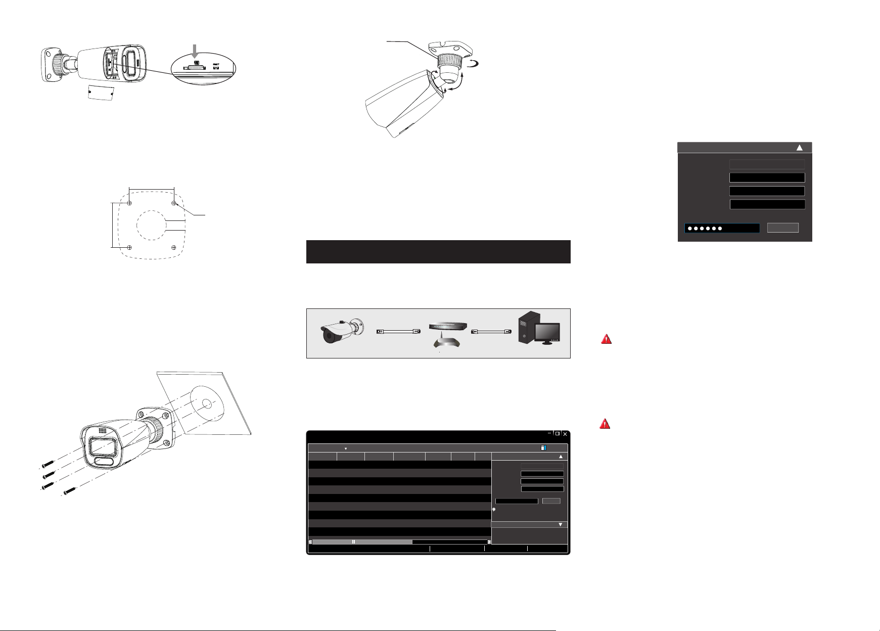
Insert a micro SD card
Fixed Ring
360° Rotation
360° Pan
90° Tilt
③ Modify the IP ad dress. The de fault IP addres s of this cam era is
192.168.226 .201. Click the in formati on of the camera lis ted in the
above table to sh ow the netw ork inf ormatio n on the righ t hand.
Modify the IP ad dress and g atewa y of the came ra and make s ure its
network addre ss is in the sa me loca l network s egment as that of th e
computer. Please modify t he IP addr ess of your device a ccordin g
to the practica l situati on.
② Drill the screw h oles and th e cable hole on the wa ll accord ing to
the drill templ ate.
48.08mm
∅4.6
48.08mm
③
Route and connect the cables .
④ Secure the camera to the wall with the screws provided.
Bracket adjustment. Before adjustment, preview the image of the
⑤
camera on a monitor and then loosen the fixed ring to adjust the view
angle of the camera .
⑥ Tig hten the fi xed ring to c omplete the inst allatio n.
Network Connection
5
● Access the cam era through IP- Tool
Switc h
IPC
Net work Cabl e Net work Cabl e
Route r
① Make sure that the camera and the PC are well connected via LAN.
② Find the IP-Tool from the CD and th en instal l it in the computer.
After tha t, run the IP-Tool as shown below.
Dev ice Net work Se arch
Imm ediat e Refre sh
Devi ce Name Devi ce Type IP Addr ess Http P ort Data P ort
name
name
name
Total De vice: 3
IPC
IPC
IPC
Prod uct Mod el
unkn own
192. 168.2 26.20 1
unkn own
192. 168.1 .2
unkn own
192. 168.1 .3
Loca l IP Addre ss:19 2.168 .1.4
Subn et
80
9008
80
9008
80
9008
Subn et Mask :255. 255.2 55.0 Gate way: 19 2.168 .1.1 DNS:21 0.21 .196. 6
Modi fy Netw ork Par amete r
255. 255.
Mac Add ress
255. 255.
IP Addr ess
Subn et Mask
255. 255.
Gate way
i
Tip: E nter th e admin istra tor pas sword, and
then m odify t he netw ork par amete rs.
Restore IPC Default Configuration
CE :98 : 23 :75 :3 5 :22
192 . 168 . 226 . 20 1
255 . 25 5 . 255 . 0
192 . 168 . 226 . 1
MENU
Compu te r
Abo ut
Modi fy
Modify Network Parameter
Mac Address
IP Add re ss
Subnet Mask
Gateway
CE :98 :23 :75 :35 :22
192 .168 . 1 . 201
255 . 255 . 255 . 0
192 .168 . 1 . 1
Modify
For example, th e IP addre ss of you r compute r is 192.168.1.4 . So the
IP address of the camera shall be changed to 192.168.1.X and the
gateway shall be changed to 192.16 8.1.1. After modification, please
enter the password of the administrator and click “Modify” button to
modify the sett ings.
The defaul t passw ord of the ad ministr ator is “ 123 45 6” .
④ Double-click the camera listed in the IP-Tool or manually enter the
IP address in the address ba r of the web br owser t o connect I P-CAM.
Then follo w direc tions to do wnload an d insta ll the plug in.
⑤ Enter the usern ame and pas sword i n the login i nterfac e.
The defaul t usern ame is ad mi n; the defa ult pas sword is 12 345 6.
450043001346 A0
 Loading...