

TVT Digital TD-3300H2, TD-3500H8 Quick Start Manual
AUDIO
OUT
Internet
DC12V
USB3. 0
LAN
VGA
AUDIO
IN
Network Video Recorder
Quick Start Guide
1. Notes
● Pl ease r ead t his i nst ruct ion c aref ully for c orre ct us e of th e prod uct a nd
pre serve i t for re fere nce pur poses .
● All t he exam ples a nd pic tures u sed her e are for r efer ence o nly.
● Th ere ma y be se vera l tech nica lly in corr ect pl aces o r pri ntin g err ors i n
thi s manua l. The up dates w ill be ad ded in to the n ew vers ion of th is manu al.
The c onten ts of th is man ual are s ubjec t to chan ge wit hout n otic e.
● This device shoul d be operate d only from the type of power source indic ated
on the ma rking lab el. The volta ge of the power mu st be verifi ed before u sing
the sam e.
Please check the devic e and the accessories after getting the devi ce. If there are
any dam ages, sh ortage s or defe cts, pl ease con tact you r dealer immed iatel y.
2. Packing Check
This serie s of th e produ ct supp orts 2 S ATA hard drive s. Please make sure that
the device is powered off before the instal lation. The pictures of the ins tallation
are only for refer ence, please take the real obj ect as the standard.
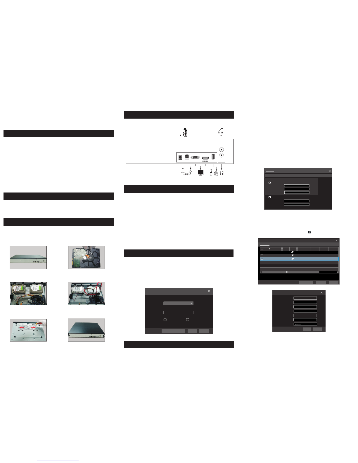
3. HDD Installation
The i nterf aces of t he rear p anel ar e for ref erenc e only.
4. Rear P anel In struc tion
5. Start up & Shutdown
7. Network Configuration
You must configure the wizard if you star t the NVR for the first time. You can
skip th e settings of w izard nex t time. The de fault usern ame is admi n and the
passw ord is set by you rself whe n you confi gure the wi zard for th e first tim e.
Click “ Start” and se lect “Log in”. This wi ll take you to se e a login box . Input
defau lt username a nd passwo rd you set an d you can see t he live ima ge.
►St artu p
① Con nect th e monit or and th e power.
② The d evice w ill boo t and the p ower in dicato r will di splay b lue.
③ A wizar d window w ill pop u p.
►Sh utdo wn
Go to “ Main Me nu” and t hen sel ect “Sh utdown ” icon. Th is will br ing up a
shu tdown w indow. Th e devic e will sh ut down by c licki ng “OK” b utton .
The n disco nnect t he powe r.
6. Login
Aft er you fi nish add ing IP cam eras, y ou can se e the live i mages t hroug h the
mon itor of t he NVR. Th e follo wing wil l mainl y intro duce ho w to add the I P
cam eras vi a LAN/WAN.
►LAN
① Set the network of the NVR. Go to Start → Settings → Network →TCP/IPv4.
Input IP address, subnet mask, gateway, etc. If using DHCP, please enable DHCP
in both the NVR and the rout er.
② Go to Start → Set tings → Net work → Port . Input HTT P port (the de fault
value is 80), server por t (the default port is 6036).
③ Click “Apply” to save th e settings.
Port
TCP/ IPv4
DDNS
E-ma il
NAT
IP Addre ss Sett ings
Obtain a n IP addr ess aut omati cally
Ether net Port 1 ( O nline )
Obatin D NS serv er addr ess aut omati cally
IP Addres s
Prefer red DNS
192 . 168 . 1 . 2
0 . 0 . 0 . 0
192 . 168 . 1 . 1
192 . 168 . 1 . 1
0 . 0 . 0 . 0
Subnet M ask
Altern ate DNS
Gatewa y
UPnP Netw ork Sta tus
④ Go to Start → Settings → Camera → Add Camera. The NVR will automatically
refres h the cameras se arched. The IPC w hich support s the Onvif pro tocol may
be added m anually. If the IPC s earched is not i n the same local n etwork as the
NVR, you s hould select t he device and cl ick to modif y the IP address.
4.0.0 .1.be ta1
Versio n
1
2
192.1 68.1. 20
192.1 68.1. 38
XXX80
80
80
XXX
XXX
XXX
3.4.2
3.4.2
255.2 55.25 5.0
255.2 55.25 5.0
No.
IP Addre ss
EditPort
Proto col Model
Subne t Mask
3
192.1 68.2. 45
XXXXXX
255.2 55.25 5.0
Quic kly Add
Manu ally Ad d
Add Ca mera
Selec ted: 1/ 3
Add
Defau lt Pass word
Remai n Bandw idth: 1 08 / 120 Mb
Cance l
Mac Addr ess
IP Addre ss
Port
CE :98 :2 3 :75 :35 : 22
Edit I P Camer a
80
192 .16 8 . 1 . 45
255 . 255 . 2 55 . 0
admin
192 .16 8 . 1 . 1
Subne t Mask
Usern ame
Gatew ay
Passw ord
OK Canc el
⑤
Edi t Camer a”
Che ckmar k the devi ce you wan t to add an d then cl ick “Ad d” butto n.The
NVR w ill aut omatic ally ref resh th e camer as and re turn to “
int erfac e.
User name
Pass word
admi n
Log in
Ente r Passw ord
Disp lay Pas sword Log In Au tomat icall y
Logi nEdit S ecuri ty Ques tion Canc el
① Loo sen the s crews t o open th e
cov er.
② Scr ew the s crews i nto the h oles of
HDD , but not t ighte n them.
③ Put t he HDDs o nto the b ottom
of th e devic e.
④
Con nect th e power a nd data
cab les.
⑤ Turn o ver the m achin e and sec ure
the H DD with t he scre ws.
⑥ Ins tall ba ck the co ver and s ecure
it wi th the sc rews.
10. Manual Recording
8. UPnP
9. NAT
11. Play back
“O nli ne” s tat us me ans c onne ctin g the d evi ce su cces sfu lly a nd yo u wil l
se e the liv e ima ge. You m ay sel ect th e adde d devic e and cl ick b utto n to
mod ify ch anne l, IP add ress , ect.
DeleteEdit
Displ ay Pass word
IP Came ra Name
IP Addre ss
Model
Edit I P Camer a
XXX
192 .16 8 . 1 . 58
80
admin
XXX
Port
Usern ame
Proto col
Passw ord
IP Came ra 3
OKTest Canc el
1
2
192.16 8.1.2 0IP Camer a 1
192.16 8.1.3 8IP Camer a 2
XXX
80
XXX
Online
XXXOfflin e
XXX80
Remain B andwi dth: 85 / 1 20 Mb
No. C amera N ame
IP Addres s
Port
Protoc ol Model
Previe w
Status
Edit C amera
Edit C amera G roup
Searc h Camer a
3
192.16 8.1.4 5IP Camera 3
XXXOnli ne XX X80
►WAN
① Set the network of the NVR. Go to Start → Settings → Network → TCP/IPv4.
Input static IP address or enable PPPoE and then input the user name and password
received from your ISP.
② Go to Start → Set tings → Cam era. Click “Add Camera ” or be hind the
column of the search cam era and select “Manually Add” to add the IP cameras.
Input I P address, se rver port, username an d password of the IP came ra. The IP
camera must be connect ed over WAN. And here the IP address of the IP camera
must be a WAN IP address.
►NAT Settings
① The NVR shall be po wered on and connected t o the network.
② Go to Start → Sett ings → Network → TCP/IP v4. You can obtain the IP
address, sub net mask and gateway au tomatically. You can also manua lly enter
them accordi ng to the actual networ k situation. Please ma ke sure the network
segment is the s ame as that of the networ k which is used.
③ Set t he prefer red or alte rnative D NS Server . Click “A pply” to sa ve the
parameters .
④ Go to Start → Sett ings → Network → NAT tab. Enable NAT and select
the NAT Server (The default NAT Server is nat. autonat.com). Clic k “Apply”
to save the para meters.
TCP/ IPv4
Port UPnP NAT
DDNS
E-ma il Netw ork Sta tus
nat.a utona t.comNAT Serv er
Enab le
Apply
►NAT Acces s
After f inishing th e NAT setti ngs, you ca n input www.a utonat. com in the IE
add ress ba r and the n press e nter to g o to the f ollow ing inte rface. If you a re
the fir st time to acce ss the NAT, you shall d ownlo ad and i nstall the Acti veX
acc ordin g to the popup t ips. Afte r insta lling Ac tiveX s ucces sfull y, it will
pop the l ogin box.
Be for e reco rdin g, ple ase in stal l and fo rmat a H DD. In t he liv e inte rfac e
yo u can s ee the m enu to olba r. Cli ck but ton to s tart r ecor ding . Clic k
it a gai n to sto p reco rdin g. You ca n als o cli ck to ch eck th e stat us of
th e rec ordi ng.
►Inst ant p lay bac k
Clic k “Instant Pl ayba ck” in t he rig ht-cl ick me nu of th e camer a’s prev iew
win dow to s elec t or dra g the pla ybac k prog ress b ar to cha nge th e play back
tim e to pla y back t he rec ord.
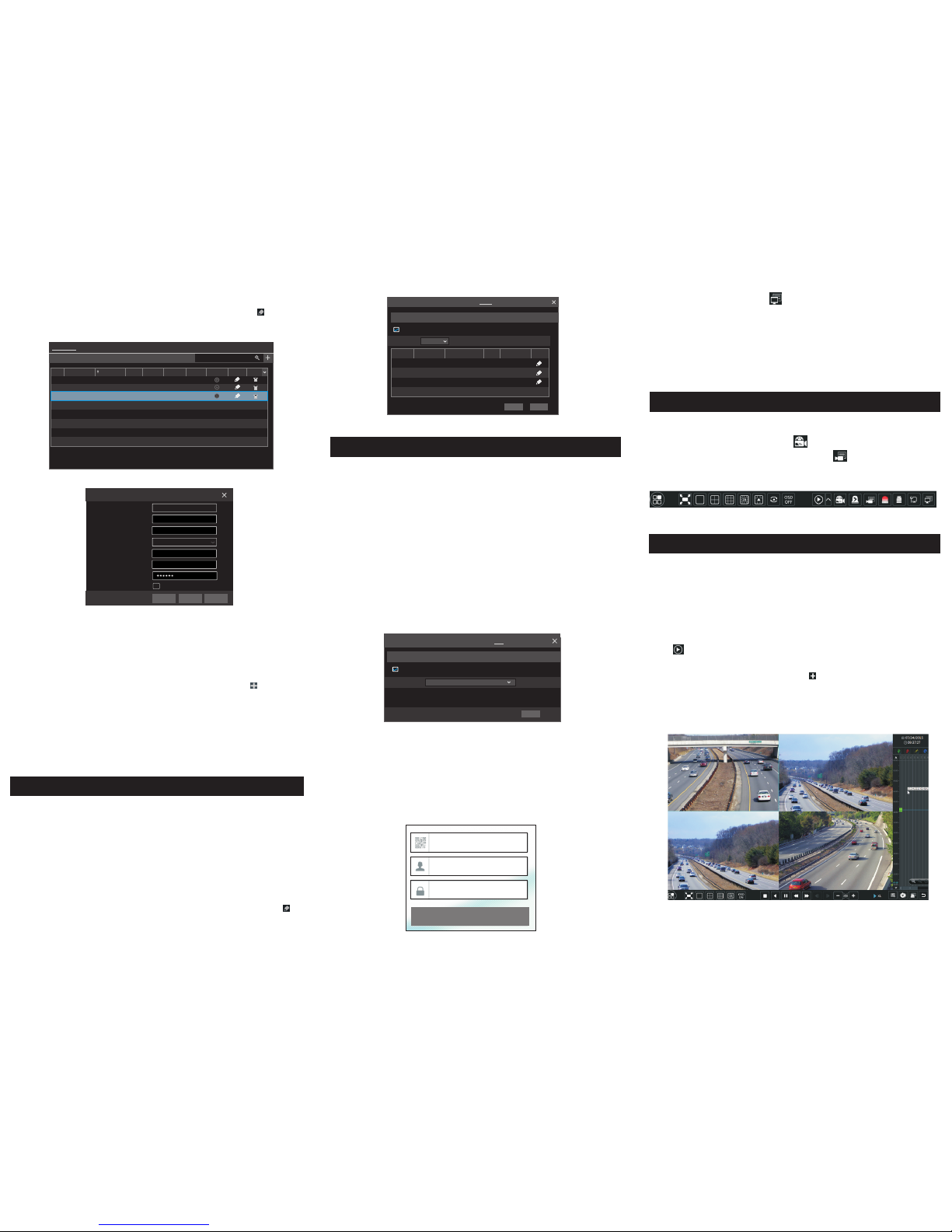
►General playback
Click on the t ool bar at the bott om of the live prev iew interface or c lick
Start → Pla yback to go to the pl ayback interf ace as shown below. You can also
add the pla yback cameras m anually. Click in the play back window to po p
up the “Add Camera” window. Check the cameras in the window and then click
“Add” to ad d playback came ra. The record file s of the added play back camera
will be pla yed in the playback i nterface.
You can us e the UPn P fun ction t o enable t he fast co nnect ion of th e devic e to
WAN via a rou ter with out por t mappi ng.
① Go to S tart → Se ttings → N etwork → U PnP, and ena ble UPn P and th en
cli ck “App ly” butt on to save .
② Ena ble the U PnP funct ion in th e route r.
③ Click “R efresh” b utton to refr esh the UPnP statu s. If the UPnP status w ere
sti ll “Inv alid UPn P” after r efres hing it f or seve ral time s, the po rt woul d be
wro ng. Pl ease c hang e the m appin g type to “M anua l” and then c lick to
mod ify the p ort unti l the UPnP s tatus t urns to “ valid UP nP”.
HTTP Por t
Serve r Port
80
6036
8018 3.17. 254.1 9 Valid UPn P
Valid UPn P
Inval id UPnP
6036183.1 7.254 .19
Port Type
Exter nal Por t
Exter nal Addr ess
UPnP Sta tus E dit
Port
RTSP Por t
554
554
TCP/ IPv4
Port UPn P
DDNS
E-ma il NAT N etwor k Statu s
AutoMap Type
UPnP
NAT
Enabl e
Refre sh Apply
450 04100 0844 A1
Devi ce Serial N umber: C lick on the m enu bar at th e bottom of t he live
inte rface to ch eck the se rial numb er or go to Sta rt → Settin gs → Netwo rk →
Netw ork Statu s to check t he serial n umber of th e NVR).
User name: The u sernam e of the NVR . The de fault us ername is a dmin.
Pass word: The p asswor d of the NVR . The pa sswor d is set by yo urself w hen
you co nfigure t he wizar d for the fir st time.
Ent er Pass word
Ent er User name
Ent er devi ce seri al numb er
Log in
 Loading...