

TVT TD-9521E3 Quick Start Manual
Network Camera
Quick Star t Guide
■ Please read thi s instruc tion carefully b efore ope rating the unit
and keep it for fur ther refe rence.
■ All the example s and pictu res used here are fo r referen ce only.
■ The contents of t his manua l are subject to cha nge witho ut
notice.
Warning and Caution
1
■ If the product do es not work p roper ly, please con tact your d ealer
or the nearest se rvice cen ter. Never a ttempt to disass emble the
camera yourse lf. (We shall not be r esponsible for a ny proble ms
caused by unaut horized r epair o r mainten ance.)
■ Do not allow wate r or liquid i ntrus ion into th e camera.
■ In the use of the pro duct, you m ust be st rict comp liance wi th the
electrical sa fety regu lations of the nat ion and reg ion. When the
product is moun ted on wall o r ceili ng, the dev ice shall b e firml y
fixed.
■ Do not use camera b eyond spe cified voltage r ange.
■ Do not drop the cam era or subj ect it to physical s hock.
■ Do not directly t ouch the ca mera when instal ling.
■ Avoid touching t he camera l ens.
■ If cleaning is ne cessary, ple ase use clean clot h to wipe it ge ntly.
■ Do not aim the came ra at the sun o r extra bright pla ce.
■ Do not place the camera in extremely hot, cold (the operating
temperature shall be -30˚C~60˚C), dusty or damp locations, and do
not expose it to high electromagnetic radiation.
■ To avoid heat a ccumulation, g ood venti lation is requir ed for
operating env ironmen t.
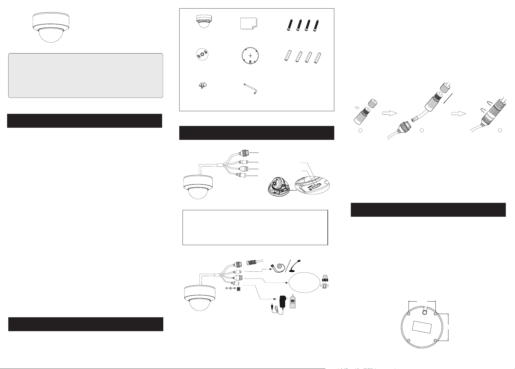
Camer a
CD
Rubbe r pl ug
Overview
3
Ethernet connect or
1
Audio input conn ec to r
2
Alarm input/ou tp ut
3
Quick s ta rt g uide
Drill t em pl ate
Screw dr iv er
M
R
A
L
A
RM
A
L
A
4 3 2 1
DC12V
Alar m Connect ion
●
Ala rm Input : Join the grounding e nd s of t he s en so r an d the camera and then
connect the sign al c ab le o f th e se ns or to the alarm input port (ALM-INA )
of the camera.
Tapp in g screws × 4
Alarm Output: Loo se n th e screws in the alarm output port. Then insert the
signal wires of th e al ar m ou tp ut d ev ices into the port of OPEN and COM
separately. Finally tighten the s cr ew s. S om e of t he external alarm output
devices need the pow er s up pl y.
Plast ic p lu g ×4
1
2
3
4 3 2 1
5
6
4
● Connecting N etwork Cable
1
2
① Loosen the nut fr om the main e lement.
② Run the network c able (wit hout RJ 45 connect or) throu gh the
both elements . Then crimp th e cable wit h RJ 45 connector.
③ Connect the cab le to the her metic connecto r. Then tig hten the
3
nut and the main co ver.
Installation
Power connecto r
4
Micro SD Card Slot
5
Reset
6
4
Please make sur e that the wa ll or ceiling is str ong enoug h to
withstand 3 tim es the weig ht of the c amera. Please install and use
the camera in the dry environment. You'd better install back the lower
p
a
y C
t
i
r
u
c
e
S
dome less than 4 hours after removing it. Do n ot remove t he protec tion
film until fini shing the i nstallation.
1-- ALM-C OM
2-- ALM-O PEN
3-- ALM-I NA
4-- ALM-G ND
① Attach the drill template to the place where you want to fix the camera
and then drill the screw holes and the cable hole on the wall according
to the drill template.
74.3
(mm )
Package
2
* 1 It is recommended to inst all th e security cap fo r out do or inst al la tion.
* 2 If the Po E sw it ch is used to p ow er t he came ra , DC 12V power su ppl y is n ot
req ui red .
74.3
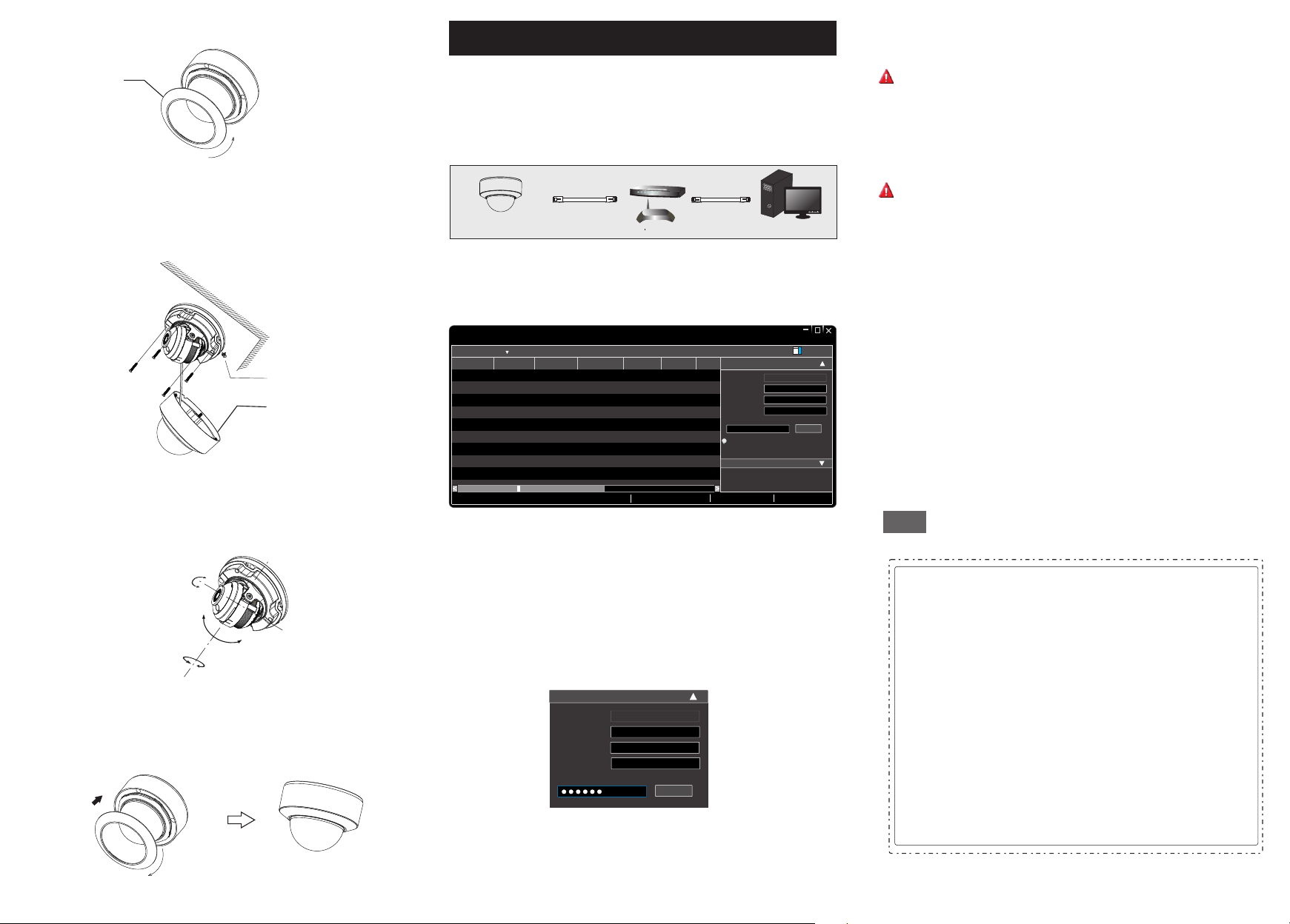
② Rotate the trim r ing antic lockwise to remo ve it from th e camera.
Network Connection
5
modification, please enter the password of the administrator and click
“Modify” button t o modify th e settings.
Trim ring
Loosen the scre ws to open th e lower dome.
③
④ Route an d connect t he cables .
⑤ Secure the came ra to the wal l with screws prov ided as sho wn
below.
Rubber P lu g
Lower dome
⑥
Three-axis ad justmen t. Before adjust ment, vie w the image of
the camera on a mon itor and th en adjust the came ra accord ing to
the figure belo w to get an opt imum angle.
Pan 0°~355°
Rotation 0°~35 5°
Install the low er dome bac k to the camera and fi x it with the
⑦
Tilt 0°~67°
screws. Th en put th e trim ring o nto the low er dome a nd then rot ate
it clockwise un til it is loc ked.
In LAN, there are t wo ways to ac cess th e camera. 1 . Access Throu gh
IP-Tool ; 2. Direct Ac cess Throug h WEB Browser
● Access Through IP-Tool
Switc h
IPC
Net work Cabl e Net work Cabl e
Route r
① Make sure that the camera and the PC are connected to the local
network.
② Install the IP- Tool from the CD a nd run it aft er installatio n.
Dev ice Net work Se arch
Imm ediat e Refre sh
Devi ce Name Devi ce Type IP Addr ess Http P ort Data P ort
name
name
name
Total De vice: 3
IPC
IPC
IPC
Prod uct Mod el
unkn own
192. 168.2 26.20 1
unkn own
192. 168.1 .2
unkn own
192. 168.1 .3
Loca l IP Addre ss:19 2.168 .1.4
Subn et
80
9008
80
9008
80
9008
Subn et Mask :255. 255.2 55.0 Gate way: 19 2.168 .1.1 DNS:21 0.21 .196. 6
Modi fy Netw ork Par amete r
255. 255.
Mac Add ress
255. 255.
IP Addr ess
Subn et Mask
255. 255.
Gate way
i
Tip: E nter th e admin istra tor pas sword, and
then m odify t he netw ork par amete rs.
Restore IPC Default Configuration
CE :98 : 23 :75 :3 5 :22
192 . 168 . 226 . 20 1
255 . 25 5 . 255 . 0
192 . 168 . 226 . 1
③ Modify the IP ad dress. The de fault IP addres s of this cam era is
192.168.226 .201. Click the in formati on of the camera lis ted in the
above table to sh ow the netw ork inf ormatio n on the righ t hand.
Modify the IP ad dress and g atewa y of the came ra and make s ure
its network add ress is in th e same lo cal netwo rk segment as the
computer’s. Ple ase modif y the IP add ress of y our devic e according
to the practica l situati on.
Mod ify Net work Pa ramet er
Mac Ad dress
IP Add re ss
Sub net Mas k
Gat eway
CE :9 8 :23 :75 : 35 :22
192 . 16 8 . 1 . 201
255 . 2 55 . 255 . 0
192 . 16 8 . 1 . 1
Mod ify
MENU
Compu te r
Abo ut
Modi fy
The defaul t passw ord of the ad ministrator is “ 123 45 6” .
④ Doub le-clic k the IP add ress and then the sy stem will p op up the
web browser to co nnect IP- CAM. Fo llow dire ctions to downlo ad
and install the plugin in the computer. Then enter the user name and
password in the login interface.
The defaul t usern ame is ad mi n; the defa ult pas sword is 12 345 6.
● Direct Acces s Through WEB Browser
① Make sure that the camera and the PC are connected via LAN.
② Find the IP-Tool from the CD and th en instal l it in the computer.
After that, run t he IP-Tool.
③ Modify the IP ad dress and m ake sur e its netwo rk address is in the
same local network segment as the computer ’s.
④ Open your web browser and enter the modified IP address in the
address bar to log in the web client. Follow directions to download
the plug-in in the computer. After that, enter the default user name
and password to log in.
Tips
Tran sp are nt D om e Maint en an ce
Tra nspar en t do me is an opti ca l el ement w hi ch i s made of pla st ic s. As dirt ,
dust or f in ge rprints o n th e dome will r ed uc e the clari ty o f the image , pl ea se
keep it c le an i n the cou rs e of i nstalli ng o r us ing but do no t di rectly to uc h or
wipe it . If t he re is any d ir t or d ust, plea se f ol low these c le aning tip s to c le an
your do me c am era.
* If ther e is d us t on the do me , pl ease use a dr y so ft b rush to gen tl y brush it .
* If ther e is w at er or gre as e on t he dome, pl ea se g ently wip e off the w at er o r
greas e wi th a s oft clo th . Then us e an ot her clean c lo th w ith a lit tl e ne utral
deter gent to wip e it s ev eral ti me s un til it is cle an . Fi nally, d ry i t with a soft
cloth .
* If ther e ar e fi ngerp ri nt s on the dome , pl ea se use a clea n co tton clot h or l en s
clean in g wi pe with a l it tl e neutral d et ergen t to w ip e it seve ra l ti mes and
then dr y it w it h a soft cl ot h.
For example, th e IP addre ss of you r compute r is 192.168.1.4 . So the
IP address of th e camera sh all be changed to 19 2.168.1 .X. After
450043001271 A0
 Loading...