

TVT TD-9423E3 Quick Start Manual
Network Camera
Quick Star t Guide
Camer a
Quick s ta rt g uide
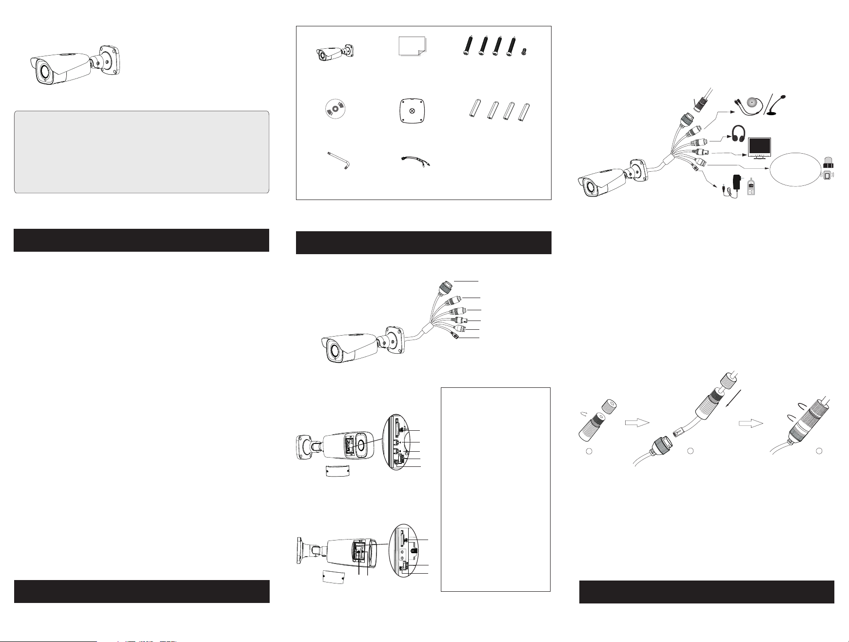
4 tapping screws PA4 ×2 5
1 machine screw PW M3 ×5
* 1
It is rec ommende d to i ns tall th e se cu rity cap fo r ou td oor ins ta llati on .
* 2 Thi s se ries can be p ow ered by D C 12 V/ PoE pow er s upply. I f th e Po E switch is
used to p ow er the ca me ra , DC12V p ow er supp ly i s no t req ui red.
ap
y c
t
uri
c
e
S
■ Please read thi s instruc tion carefully b efore usi ng the pr oduct
and keep it for fur ther refe rence .
■ All the example s and pictu res used here are fo r referen ce only.
■ The contents of t his manua l are subject to cha nge witho ut
notice.
Warning and Caution
1
■ If the product do es not work p roper ly, please con tact your d ealer
or the nearest se rvice cen ter. Never a ttempt to disass emble the
camera yourse lf. (We shall not be r esponsible for a ny proble ms
caused by unaut horized r epair o r mainten ance.)
■ Do not allow wate r or liquid i ntrus ion into th e camera.
■ In the use of the pro duct, you m ust be st rict comp liance wi th the
electrical sa fety regu lations of the nat ion and reg ion. When the
product is moun ted on wall o r ceili ng, the dev ice shall b e firml y
fixed.
■ Do not use camera b eyond spe cified voltage r ange.
■ Do not drop the cam era or subj ect it to physical s hock.
■ Avoid touching t he camera l ens.
■ If cleaning is ne cessary, ple ase use clean clot h to wipe it ge ntly.
If the device wil l not be used f or a long t ime, plea se cover th e lens
cap to protect th e device fr om dirt.
■ Do not aim the came ra at the sun o r extra bright pla ce.
■ Do not place the camera in extremely hot, cold (the operating
temperature shall be -30˚C~60˚C), dusty or damp locations, and do
not expose it to high electromagnetic radiation.
■ To avoid heat a ccumulation, g ood venti lation is requir ed for
operating env ironmen t.
Package
2
CD
Screw dr iv er
Overview
3
Type A: M ot or ized zoom camera
Type B : Ma nual zoom camera
9B
Drill t em pl ate
8B
CVBS& DC
IN cabl es
7
8A
9A
10
11
7
10
11
Plast ic p lu g ×4
1
2
3
4
ARM
AL
4 3 2 1
5
6
1 Ethernet Connect or *
2 Audio Input (
3 Audio Output (
4 CVBS Video Output
5 Alarm Input/Ou tp ut
6 Power Connector *
7 Micro SD Card Slot
8A Zoom +
9A Zoom -
8B Focus
9B Zoom
10 DC IN & CVBS Inter face
11 Rese t
MIC)
HP)
1-- ALM-C OM
2-- ALM-O PEN
3-- ALM-I NA
4-- ALM-G ND
Alar m Connect ion
●
ALARM
4 3 2 1
DC1 2V
Alarm Input: Join the gr ounding ends of th e sensor an d the camera
and then connec t the signa l cable of the senso r to the alar m input
port of the camer a.
Alarm Output: Loosen the s crews in th e alarm output por t. Then
insert the sign al wires of t he alar m output de vices int o the por t of
COM an d OPEN sepa rately. Fina lly tighten the sc rews. Som e of the
external alar m output de vices need the pow er supply.
● Connecting N etwork Cable
1
2
3
① Loosen the nut fr om the main e lement.
② Run the network c able (wit hout RJ 45 connect or) throu gh the
both elements . Then crimp th e cable wit h RJ 45 connector.
③ Connect the cab le to the her metic connecto r. Then tig hten the
nut and the main co ver.
Installation
4
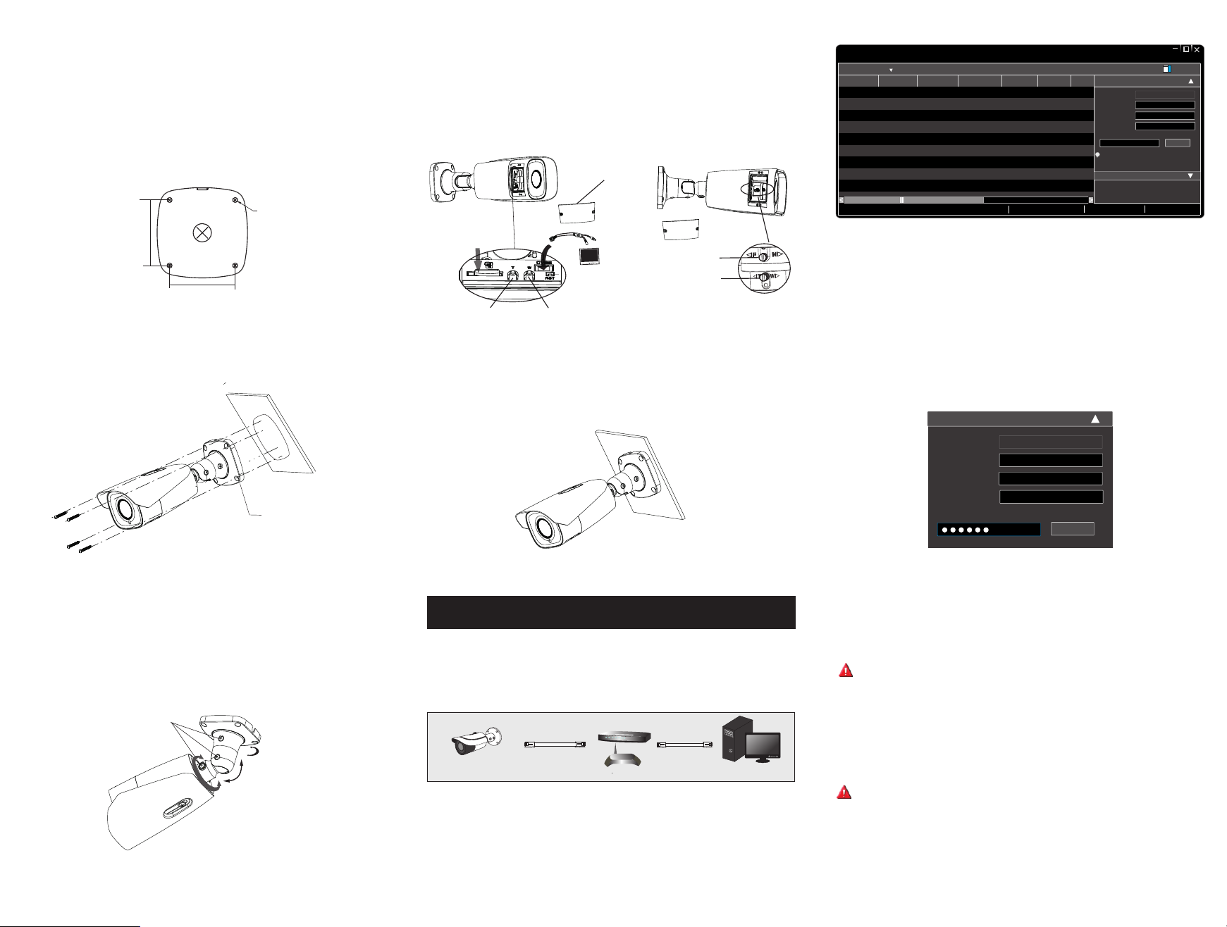
Please make sur e that the wa ll or ceiling is str ong enoug h to
withstand 3 tim es the weig ht of the c amera. Please install the camera
in the dry environment. You'd better install back the cover
of the camera less than 4 hours after removing it.
① Drill the sc rew holes a nd the cable hole (i f you want to r oute
through the cei ling) on th e wall or ceiling ac cording t o the dri ll
template.
Open the cover of t he camera a s shown i n the follo wing figure
⑤
and then insert a m icro SD car d. After tha t, adjust Zoom or Fo cus
to obtain an opti mum image . Press t he T or W but ton for Typ e A;
adjust the Focu s and Zoom sc rews fo r Type B. Bef ore adjus tment ,
view the image of t he camera o n a monitor.
Cove r
Dev ice Net work Se arch
Imm ediat e Refre sh
Devi ce Name Devi ce Type IP Addr ess Http P ort Data P ort
name
name
name
Prod uct Mod el
unkn own
unkn own
unkn own
192. 168.2 26.20 1
192. 168.1 .2
192. 168.1 .3
IPC
IPC
IPC
80
9008
80
9008
80
9008
Subn et
Modi fy Netw ork Par amete r
255. 255.
Mac Add ress
255. 255.
IP Addr ess
Subn et Mask
255. 255.
Gate way
i
Tip: E nter th e admin istra tor pas sword, and
then m odify t he netw ork par amete rs.
Restore IPC Default Configuration
Abo ut
CE :98 : 23 :75 :3 5 :22
192 . 168 . 226 . 20 1
255 . 25 5 . 255 . 0
192 . 168 . 226 . 1
Modi fy
∅5
64.6mm
64.6mm
② Route the cable s and conne ct the relevant ca bles.
③ Fasten the moun ting base t o the wall with the sc rews prov ided.
Moun ti ng Base
④ Bracket adjustment. Before adjustment, preview the image of the
camera on a monitor (See the left figure of step ⑤) and then loosen the
fixed screws to adjust the view angle of the camera. After that, tig hten
the fixed screw s.
Fixe d Sc rews
Pan 36 0°
Tilt 9 0°
Rota te
360°
Inse rt a m icro
SD car d
Focu s
Moni to r
Zoom +
Zoom -
Type A: M ot or ized zoom camera
⑥
Install the cov er back to th e camera and fix it with the firmly
screws. ( )
Note that the cov er should n ot be ins talled un evenly.
Network Connection
5
Zoom
Type B : Ma nual zoom camera
Here w e take acce ssing IP camera via LAN for ex ample.
● Access Through IP-Tool
Switc h
IPC
Net work Cabl e Net work Cabl e
Route r
① Make sure that th e camera an d the PC are well conn ected to th e
LAN.
② Find the IP-Tool from the CD and th en instal l it in the computer.
After tha t, run the IP-Tool as shown below.
MENU
Compu te r
Total De vice: 3
Loca l IP Addre ss:19 2.168 .1.4
Subn et Mask :255. 255.2 55.0 Gate way: 19 2.168 .1.1 DNS:21 0.21 .196. 6
③ Modify the IP ad dress. The de fault IP addres s of this cam era is
192.168.226 .201. Click the in formati on of the camera lis ted in the
above table to sh ow the netw ork inf ormatio n on the righ t hand.
Modify the IP ad dress and g atewa y of the came ra and make s ure its
network addre ss is in the sa me loca l network s egment as that of th e
computer. Please modify t he IP addr ess of your device a ccordin g
to the practica l situati on.
Modify Network Paramete r
Mac Address
IP Add re ss
Subnet Mask
Gateway
CE :98 :23 :75 :35 :22
192 .168 . 1 . 201
255 . 255 . 255 . 0
192 .168 . 1 . 1
Modify
For example, th e IP addre ss of you r compute r is 192.168.1.4 . So the
IP address of the camera shall be changed to 192.168.1.X. After
modification, please enter the password of the administrator and click
“Modify” button t o modify th e setting.
The defaul t passw ord of the ad ministrator is “ 123 45 6” .
④ Doub le-clic k the IP address to o pen up the we b brows er or
manually ente r the modif ied IP address in t he addres s bar of yo ur
brow ser. Th en follow d irect ions to download and install the plugin if
it is the first time for you to log in.
⑤ Enter
the user name and p assword i n the log in interf ace.
The defaul t usern ame is ad mi n; the defa ult pas sword is 12 345 6.
450043001289 A0
 Loading...