

TVT TD-2932TD-HP Quick Start Manual
Hybrid DVR
Quick Start Guide
1. Notes
● Ple as e r ead th is in str uct io n c are fully be for e ope rat ing the uni t a nd
keep it for further reference.
● All the examples and pictures used here are for reference only.
● The contents of this manual are subject to change without notice.
● This device should be operated only from the type of power source indicated
on the marking label. The volta ge of the power must be ver ified before using
the sa me.
2. Packing Check
Please check the device and accessories after getting the device. If there are
any damages, shortages or defects, please contact your dealer immediately.
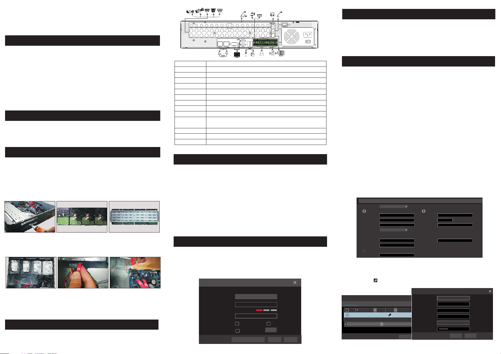
3. HDD Installation
This series of the product supports 8 SATA ha rd drives. The pictures of the
installation are only for reference, please take the real object as the standard. Please
make sure that the device is powered off before the installation.
① Remove the cover and loosen the screws to take out two mounting bars.
② Fix the HDDs on the mounting bar with screws.
③ Ins ta ll t he two mo un ting bars w it h HDDs back t o th e devic e ( It i s recomme nd ed to
ins ta ll t he copp er-pi ll ar provid ed i n case the HD Ds a re dama ge d by extern al f orces ) .
④ Con ne ct t he powe r an d data cabl es .
⑤ Install ba ck t he c ov er a nd s ec ur e it w it h th e sc re ws .
Tips: Please check the inside structure of the device and make sure the cables connected
well before installing the cover back.
4. Rear Panel Instruction
The interf ac es o f th e rear panels are f or r ef er ence only.
AUD IO IN
VID EO IN
AUD IO OUT
MIC I N
CVB S
LAN 1/2
VGA
HDM I1
HDM I2
USB 3.0/U SB
RS 48 5
ALA RM OUT
ALA RM IN
E-S ATA
Con necto rs fo r audio i npu t
Con necto rs fo r video i npu t
Con necto rs fo r audio o utp ut
Con nect to a m icr ophon e use d for two -wa y talk
CVB S video o utp ut conn ect or
RJ 45 1 000Mb ps Et herne t por ts
Con nect to m oni tor
Con nect to m oni tor, use d as main o utp ut
Con nect to m oni tor, use d as seco nda ry outp ut
Con nect to U SB st orage d evi ce or USB m ous e
K/B : conne cto r for a key boa rd. A is TX +; B is T X-
P/Z : conne cto r for a PTZ d evi ce. Y is TX+; Z i s TX-
Con necto r for a larm ou tpu t devic es
Con necto r for a larm in put d evice s, li ke sens ors
Con nect to t he HD D with e- SATA inter face
5. Startup & Shutdown
►Startup
① Con nect the mo nitor and the power.
② The d evice wil l boot and the power i ndicato r will disp lay blue.
③ A wizard wind ow will pop up.
►Shutdown
Click “Start” and then select “Shutdown” icon. This will bring up a shutdown
window. The device will shut down by clicking “OK” button. Then disconnect
the p ower.
6. Login
You must configure the wizard if you start the DVR for the first time.
username is admin and the default password is 123456.
Please change the
password as needed and then click “Edit Security Question ” to set questions
and answers for retrieving password.
Wizar d
Adm in Pass word Se tup
Use rname
Pas sword
Con firm Pa sswor d
Pat tern Lo ck
adm in
123 456
123 456
Dis play Pa sswor d
Ena ble
Log I n Aut omati cally
Edi t
Nex tEdi t ecu rity ues tion S Q Can cel
The default
7. Analog Camera Connection
First connect the camera to the DVR. Then go to Start → Settings → Camera
→ Manage Ca mera → Camera Signal to set the signal mode of camera. The
actual sig nals input shall correspond to the video mode. Please refer to User
Manual for details.
8. Network Configuration & Add IP Camera
After you finish adding IP cameras, you can see the live images through the monitor
of the DVR. The following will mainly introduce how to add the IP cameras via
LAN/WAN. This DVR has two network ports, you can select the network work
pattern as needed. Network fault tolerance and multiple address setting are optional.
Network Fault Tolerance: Bound two network ports to one IP address. This pattern
can increase the network bandwidth and form a network redundant array to share the load.
When one port goes wrong, the other port will take over the entire load immediately and
seamlessly.
Multiple Address Setting: You shall set the IP address, subnet mask, gateway and
DNS of each ethernet port respectively.
The pictures are only for reference, please refer to User Manual for details.
►LAN
① Set the network of the DVR. Go to Start → Settings → Network →TCP/IP. Enter
IP address, subnet mask, gateway, etc. If using DHCP, please enable DHCP in both the
NVR and the router.
② Go to Start → Settings → Network → Port. Enter HTTP port (the default value
is 80), server port (the default port is 6036).
③ Click “Apply” to save the settings.
IP Addr ess Set tings
Work Pa ttern (Mod ifyin g work pa ttern n eed to re boot )G atewa y
Addr ess
Subn et Mask
Gate way
Prim ary Car d
Ethe rnet Por t 1 ( Onli ne )
MCA Addr ess
MTU
Pref erred D NS
④ Go to Start → Settings → Camera → Add Camera. The DVR will automatically
refresh the list of online IP cameras which are in the same local network with
the DVR. Click to modify the IP address.
Qui ckly Ad d
Man ually A dd
No.
Addr ess
1
192. 168.2 .45
Sele cted: 1 /1
Rema in Band width : 10 / 10 Mb
Netw ork Fau lt Toleran ce
Obta in an IPv 4 addre ss auto matic ally
192 . 16 8 . 1 . 2
0 . 0 . 0 . 0
192 . 16 8 . 1 . 1
Ethe rnet Po rt 1
10 . 151 . 1 51 . 1
1500
Obta in DNS au tomat icall y
. . .
Add C amera
EditPort
80
Subn et Mask
255. 255.2 55.0
Defa ult Pas sword
Obta in an IPv 6 addre ss auto matic ally
Addr ess
Mask L ength
Gate way
Ethe rnet Por t 2 ( Onli ne )
MAC Add ress
Mac Add ress
Addr ess
Prot ocol Mode l
Subn et Mask
XXXXXX
Gate way
User name
Pass word
Add
0
Edi t IP
CE :98 : 23 :75 :3 5 :22
192 .1 68 . 1 . 45
Versi on
255 . 25 5 . 255 . 0
4.0. 0.1.b eta1
192 .1 68 . 1 . 1
admi n
OK Can cel
Canc el
⑤
Check mark the devi ce you want to add an d then click “A dd” button. The
DVR wil l automatic ally refresh th e cameras and r eturn to “Edit Ca mera”
inter face. “O nl ine” statu s mea ns co nnect in g t he de vi ce su ccess fully and
you will see t he li ve image . You may select t he a dded device a nd click
butto n to modify cha nnel, IP address , et c. You can chang e the camera na me
only wh en the added ca mera is online.
[A01 ]Came ra1
[A02 ]Came ra2
[A03 ]Came ra3
[A04 ]Came ra4
Edi t Camer a
Addr ess
192. 168.1 .45I P Camer a 1
Sear ch Came ra
Stat us
Port
Prot ocol
Onli ne
80
XXX
Prev iew
Mode l
XXX 4.1. 0.0
Versi onEdit Upgr ade
Cam era Sig nal
No. Ca mera Na me
1
2
3
4
5
10. NAT
UPn P
Enab le
Port Ty pe
HTTP P ort
HTTP S Port
Serv er Port
RTSP Po rt
AutoMap Typ e
Exte rnal Po rt
80
443
6036
554
Exte rnal Add ress
183. 17.25 4.19
183. 17.25 4.19
Port
80
443
6036183. 17.25 4.19
554
Refr esh Appl y
UPnP S tatus Edit
Valid U PnP
Valid U PnP
Valid U PnP
Inva lid UPn P
Device S erial Numb er
interf ace to check the serial numbe r or go to Start Settings Networ k
: Click on t he menu bar at the bottom of the li ve
→ → →
Networ k Status to check the serial number of the DV R).
Userna me: The username of th e DVR. The d efault use rname is admin.
Passwo rd: The password of th e DVR. The password is s et by yourself when
you conf igure the wizard for the first time.
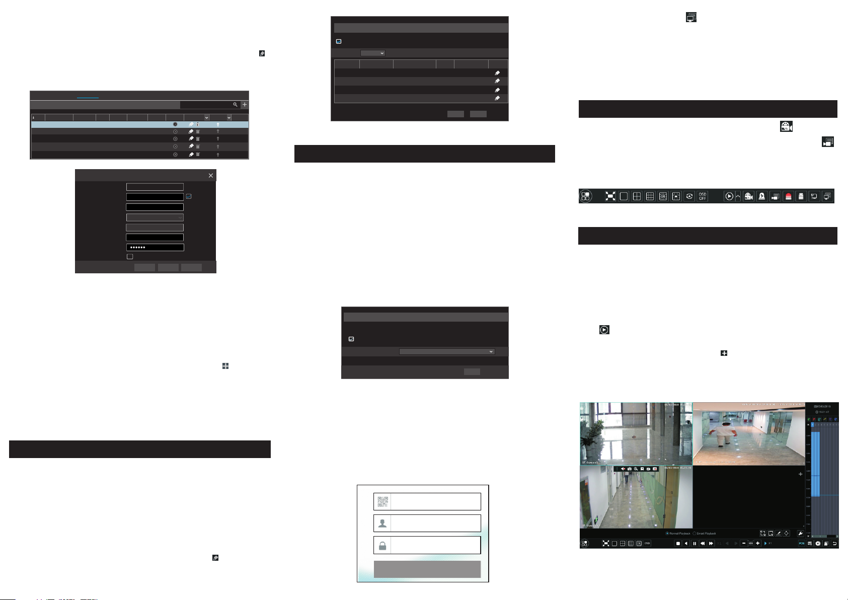
11. Manual Recording
In t he li ve in ter fac e you c an se e the m en u too lba r. C lic k bu tto n to
st art r eco rdi ng. C lic k it ag ai n to st op re cor din g. You can a lso c lic k
to c hec k the s tat us of t he re cor din g.
Edi t Camer a
Came ra Name
Addr ess
Port
Prot ocol
Mode l
User name
Pass word
IP Cam era 1
192 . 168 . 1 . 58
80
XXX
XXX
admi n
Disp lay Pas sword
Sync t o IPC
OKTest Can cel
►WAN
① Set the network of the DVR. Go to Start → Settings → Network → PPPoE.
Input static IP address or enable PPPoE and then input the user name and password
received from your ISP.
② Go to Start → Settings → Camera. Click “Add Camera” or behind the
column of the search camera and select “Manually Add” to add the IP cameras.
Input IP address, server port, username and password of the IP camera. The IP
camera must be connected over WAN. And here the IP address of the IP camera
must be a WAN IP address.
9. UPnP
You can use the UPnP function to enable the fast connection of the device to
WAN via a router without port mapping.
① Go to Start → Settings → Network → UPnP, and enable UPnP and then
click “Apply” button to save.
② Enable the UPnP function in the router.
③ Click “Refresh” button to refresh the UPnP status. If the UPnP status is
still “Invalid UPnP” after refreshing it for several times, the port may be wrong.
Please change the mapping type to “Manual” and then click to modify the
port until the UPnP status turns to “valid UPnP”.
►NAT Settings
① The DVR shall be powered on and connected to the network.
② Go to Start → Settings → Network → TCP/IP. You can obtain the IP address,
subnet mask and gateway automatically. You can also manually enter them
according to the actual network situation. Please make sure the network segment
is the same as that of the network which is used.
③ Set the preferred or alternative DNS Server. Click “Apply” to save the
parameters.
④ Go to Start → Settings → Network → NAT tab. Enable NAT and select the
NAT Server Address. Click “Apply” to save the parameters.
NAT
Vis it Addre ss www.au tonat .com
Ena ble
nat .auton at.co mNAT Ser ver Addr ess
Appl y
►
NAT Acc es s
After finishing the NAT settings, you can enter w ww.au ton at. com in t he web
addre ss bar and then p ress enter to go to t he followin g interface. If y ou are
the fir st time to acce ss the NAT, you s ha ll d ow nload and insta ll th e Ac ti veX
acco rding to t he po pup t ips. After insta lling Activ eX su cc essfu lly,
it will p op the login bo x.
Ent er devi ce seri al numb er
Ent er User name
Ent er Pass word
Login
12. Playback
Insta nt pl ayback
►
Click “Instant Pla yback” in t he r ight-cl ic k menu of the c am era’s previe w
wind ow t o select or d ra g the playb ac k progres s ba r to change t he p layback
time t o pl ay back the r ec ord.
►General playback
Click on the tool bar at the bottom of the live preview interface or click
Start → Playback to go to the playback interface as shown below. You can also
add the playback cameras manually. Click in the playback window to pop
up the “Add Camera” window. Check the cameras in the window and then click
“Add” to add playback camera. The record files of the added playback camera
will be played in the playback interface.
45004 10 01 A311 0
 Loading...