

Page 1
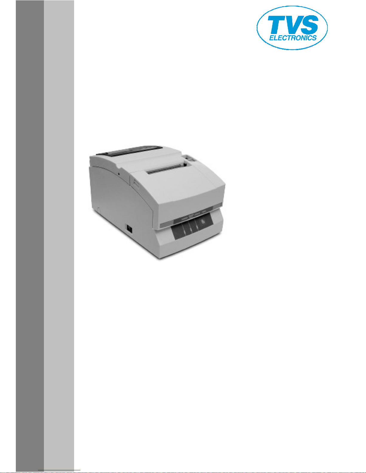
DOT MATRIX PRINTER
RP
RPRP
RP----35
3535
35
User's Manual
Page 2

Table of Contents
Table of ContentsTable of Contents
Table of Contents
Chapter1
Chapter1Chapter1
Chapter1 ............................................................................................................................. 6
Introduction
IntroductionIntroduction
Introduction ......................................................................................................................... 6
Chapter2
Chapter2Chapter2
Chapter2 ............................................................................................................................. 7
Names and Functions of Parts
Names and Functions of PartsNames and Functions of Parts
Names and Functions of Parts ........................................................................................... 7
Chapter3
Chapter3Chapter3
Chapter3 ........................................................................................................................... 11
Connecting the Power
Connecting the PowerConnecting the Power
Connecting the Power ...................................................................................................... 11
Chapter4
Chapter4Chapter4
Chapter4 ........................................................................................................................... 25
Maintenance mode
Maintenance modeMaintenance mode
Maintenance mode ........................................................................................................... 25
Chapter5
Chapter5Chapter5
Chapter5 ........................................................................................................................... 35
Appendixes
AppendixesAppendixes
Appendixes ....................................................................................................................... 35
Page 3
SAFETY INSTRUCTIONS
SAFETY INSTRUCTIONSSAFETY INSTRUCTIONS
SAFETY INSTRUCTIONS
which must be strictly observed !
which must be strictly observed !which must be strictly observed !
which must be strictly observed !
• To prevent personal injury or property
To prevent personal injury or property To prevent personal injury or property
To prevent personal injury or property damage, the following shall be
damage, the following shall bedamage, the following shall be
damage, the following shall be
strictly observed.
strictly observed.strictly observed.
strictly observed.
• The degree of possible injury and damage due to incorrect use or
The degree of possible injury and damage due to incorrect use orThe degree of possible injury and damage due to incorrect use or
The degree of possible injury and damage due to incorrect use or
improperly following instructions is described below.
improperly following instructions is described below.improperly following instructions is described below.
improperly following instructions is described below.
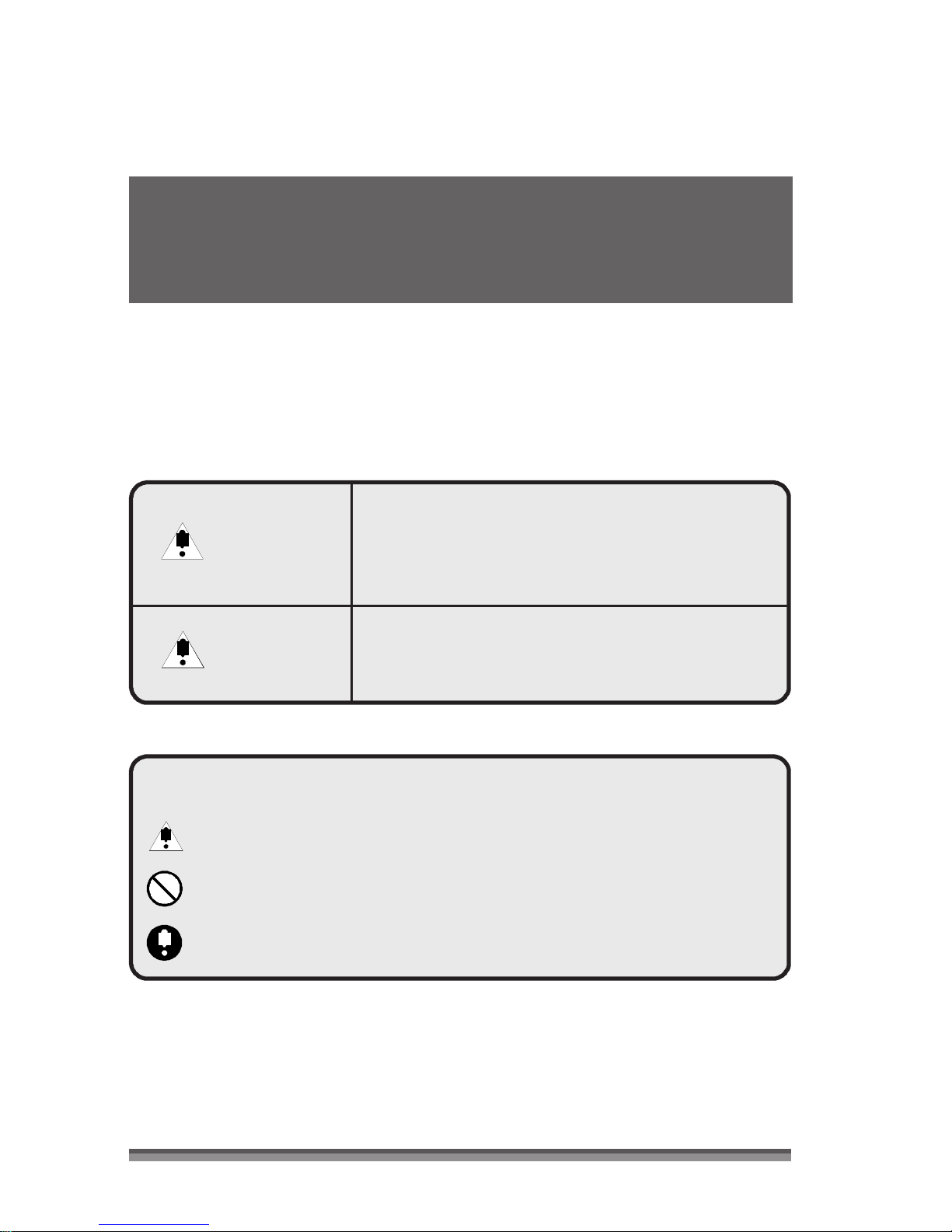
Indicates a situation which, if not observed
Indicates a situation which, if not observedIndicates a situation which, if not observed
Indicates a situation which, if not observed
Warning
WarningWarning
Warning
Caution
CautionCaution
Caution
and handled pro
and handled proand handled pro
and handled properly, could result in death
perly, could result in deathperly, could result in death
perly, could result in death
or serious injury.
or serious injury.or serious injury.
or serious injury.
Indicates a situation which, if not observed
Indicates a situation which, if not observedIndicates a situation which, if not observed
Indicates a situation which, if not observed
and handled properly, could result in injury.
and handled properly, could result in injury.and handled properly, could result in injury.
and handled properly, could result in injury.
Meaning of symbols
Meaning of symbolsMeaning of symbols
Meaning of symbols
This symbol indicates that something must be handled carefully.
This symbol indicates that something must be handled carefully.This symbol indicates that something must be handled carefully.
This symbol indicates that something must be handled carefully.
This symbol indicates som
This symbol indicates somThis symbol indicates som
This symbol indicates something that must not be done.
ething that must not be done.ething that must not be done.
ething that must not be done.
This symbol indicates something that must be done.
This symbol indicates something that must be done.This symbol indicates something that must be done.
This symbol indicates something that must be done.
2222
Page 4
Warning
WarningWarning
Warning
Never perform the following. If not avoided, these may cause damage
or trouble to the printer or cause the printer to overheat and release
smoke and cause burns or an electrical shock. If the printer is damaged
or is malfunctioning, be sure to turn the printer off immediately and
remove the power cord from the outlet, then consult our service
personnel.
• Do not place the printer in a poorly ventilated area, or shut off the air vent of
the printer.
• Do not place the printer where chemical reactions occur, such as in laboratories
or where air is mixed with salt or gas.
• Do not use a power voltage or frequency other than those specified.
• Do not plug/unplug the power cord or attach/detach the interface cable by
simply grabbing the power cord or interface cable. Do not pull or carry the
printer when the tension of the power cord or interface cable is increased.
• Do not drop or put foreign matter such as clips and pins into the printer. This
may cause problems.
• Do not plug the power cord into an outlet with many loads.
• Do not spill drinks such as tea, coffee and juice on the printer or spray
insecticide on the printer. If drink or water is spilled, first be sure to turn the
power off and remove the power cord from the outlet, then consult our service
personnel.
• Do not disassemble or modify the printer.
• Do not use this printer when any safety switch built into the product has been
cancelled without solving the problem that activated it. If you do, there is a danger
that the printer will malfunction, injuring, burning, or electrocuting you.
Discard or safely store the plastic packing bag. This bag should be
kept away from children. If the bag is pulled over a child’ s head, it may
cause suffocation.
3333
Page 5
General Precautions
General PrecautionsGeneral Precautions
General Precautions
Caution
CautionCaution
Caution
• Prior to operation, read the safety instructions carefully and observe them.
• Do not drop or put foreign matter such as clips and pins into the printer. This
may cause problems.
• Be careful when moving or carrying the printer. Dropping the printer may
cause injury or property damage.
· If this printer is accidentally dropped, be sure to notify a service person; do
not try to repair it yourself.
• Do not open the printer during printing.
• When cleaning the surface of the printer case, do not use the cloth that is
soaked in thinner, trichloroethylene, benzine, ketone or similar chemicals.
• Do not use the printer where there is a lot of oil, iron particles, or dust.
• Do not spill liquids or spray insecticide on the printer.
• Do not jolt or impact to the printer by stepping on, dropping or hitting the
printer.
• Operate the control panel properly. A careless, rough handling may cause
problems or malfunction. Do not use such sharp-edged tool as a ballpoint
pen for operation.
• Be careful of the edges of the plates so injury or property damage is possible.
• If a problem occurs during printing, stop the printer immediately and unplug
the power cord from the outlet.
• When printer trouble occurs, do not try to dissemble it. Instead, consult our
service personnel.
4444
Page 6
Precautions When Installing the Printer
Precautions When Installing the PrinterPrecautions When Installing the Printer
Precautions When Installing the Printer
Caution
CautionCaution
Caution
• Prior to operation, read the safety instructions carefully and observe them.
• Do not use or store the printer near fire, excessive moisture, in direct sunlight,
near an air conditioner or heater or other source of unusually humidity or
excessive dust.
• Do not place the printer where chemical reactions occur, such as in a
laboratory.
• Do not place the printer where air is mixed with salt or gas.
• The printer must sit on a firm, level surface where there is ample ventilation.
Never allow the printer's air vent to be blocked by an object.
• Do not put anything on the top of printer.
• Do not place the printer near a radio or television, and do not use the same
wall outlet for the printer and radio or television. Radio or television reception
could be adversely affected.
• Do not put anything on the power cord or step on it.
• Do not drag or carry the printer with the power cord or interface cable.
• Avoid plugging the power cord into an outlet with many loads.
• Do not bundle the power cord when inserting the plug.
• Always grip the plug housing, not the cord, to plug/unplug the power cord.
• Make certain the power is turned off before connecting/disconnecting the
interface cable.
• Avoid lengthening the signal cable or connecting it to any noise-producing
device. If it is unavoidable, use the shielded cable or twisted pair for each
signal.
• Place the printer near the outlet where the power cord can be unplugged
easily to shut off power.
• Use the AC outlet that accepts a three-pronged plug. Otherwise, static
electricity may be generated and there will be danger of electric shock.
· Do not carry it holding the cover.
Doing this might break its mechanisms or cause it to malfunction.
5555
Page 7

Chapter1
Chapter1Chapter1
Chapter1 Introduction
Thank you very much for purchasing the TVSE Dot Matrix Printer RP-35.
This printer is a dot matrix printer developed for use with various kinds of data
communication terminals, POS terminals, and kitchen printers.
It can be used for a wide range of applications thanks to its rich selection of functions.
Features
FeaturesFeatures
Features
Compact design
Compact designCompact design
Compact design
A paper drop in mechanism that simplifies paper loading
A paper drop in mechanism that simplifies paper loadingA paper drop in mechanism that simplifies paper loading
A paper drop in mechanism that simplifies paper loading
High speed printing to a maximum of 240cps
High speed printing to a maximum of 240cpsHigh speed printing to a maximum of 240cps
High speed printing to a maximum of 240cps
Multiple copy print
Multiple copy printMultiple copy print
Multiple copy printing (original form + 2 copies)
ing (original form + 2 copies)ing (original form + 2 copies)
ing (original form + 2 copies)
Input buffer available
Input buffer availableInput buffer available
Input buffer available
Black mark sensor mechanism
Black mark sensor mechanismBlack mark sensor mechanism
Black mark sensor mechanism
Versatile printing layout using the page mode
Versatile printing layout using the page modeVersatile printing layout using the page mode
Versatile printing layout using the page mode
Logo data or text data prepared by the user can be stored in its user
Logo data or text data prepared by the user can be stored in its userLogo data or text data prepared by the user can be stored in its user
Logo data or text data prepared by the user can be stored in its user
memory
memorymemory
memory
Built
BuiltBuilt
Built----in drawer kick
in drawer kickin drawer kick
in drawer kick----out interface
out interfaceout interface
out interface
Optional auto
Optional autoOptional auto
Optional auto----cu
cucu
cutter (full cut/partial cut)
tter (full cut/partial cut)tter (full cut/partial cut)
tter (full cut/partial cut)
Capacity for paper with widths of 76.2/69.5/57.5mm
Capacity for paper with widths of 76.2/69.5/57.5mmCapacity for paper with widths of 76.2/69.5/57.5mm
Capacity for paper with widths of 76.2/69.5/57.5mm
Parallel (IEEE and Centronics compliant) interface
Parallel (IEEE and Centronics compliant) interfaceParallel (IEEE and Centronics compliant) interface
Parallel (IEEE and Centronics compliant) interface
is available as a factory option
is available as a factory optionis available as a factory option
is available as a factory option
Selection of functions diversified by its operation panel (Soft SW setting
Selection of functions diversified by its operation panel (Soft SW settingSelection of functions diversified by its operation panel (Soft SW setting
Selection of functions diversified by its operation panel (Soft SW setting
mode)
mode)mode)
mode)
Can be wall
Can be wall Can be wall
Can be wall mounted (optional)
mounted (optional)mounted (optional)
mounted (optional)
Built
BuiltBuilt
Built----in buzzer
in buzzerin buzzer
in buzzer
Built
BuiltBuilt
Built----in or external AC adapter types available
in or external AC adapter types availablein or external AC adapter types available
in or external AC adapter types available
Dual color printing (red/black)
Dual color printing (red/black)Dual color printing (red/black)
Dual color printing (red/black)
6666
Page 8
1
Chapter2
Chapter2Chapter2
Chapter2
Names and Functions of Parts
Names and Functions of Parts
Names and Functions of PartsNames and Functions of Parts
Names and Functions of Parts
Exterior
ExteriorExterior
Exterior
AC adapter type
AC adapter typeAC adapter type
AC adapter type
Standard and auto cutter e
Standard and auto cutter eStandard and auto cutter e
Standard and auto cutter equipped
quippedquipped
quipped
models
modelsmodels
models
2
3
4
6
Built
BuiltBuilt
Built----in AC adapter type
in AC adapter typein AC adapter type
in AC adapter type
5
Operation panel
(Refer Operational Section)
Rear connectors
(Refer Rear Connectors
Section)
7
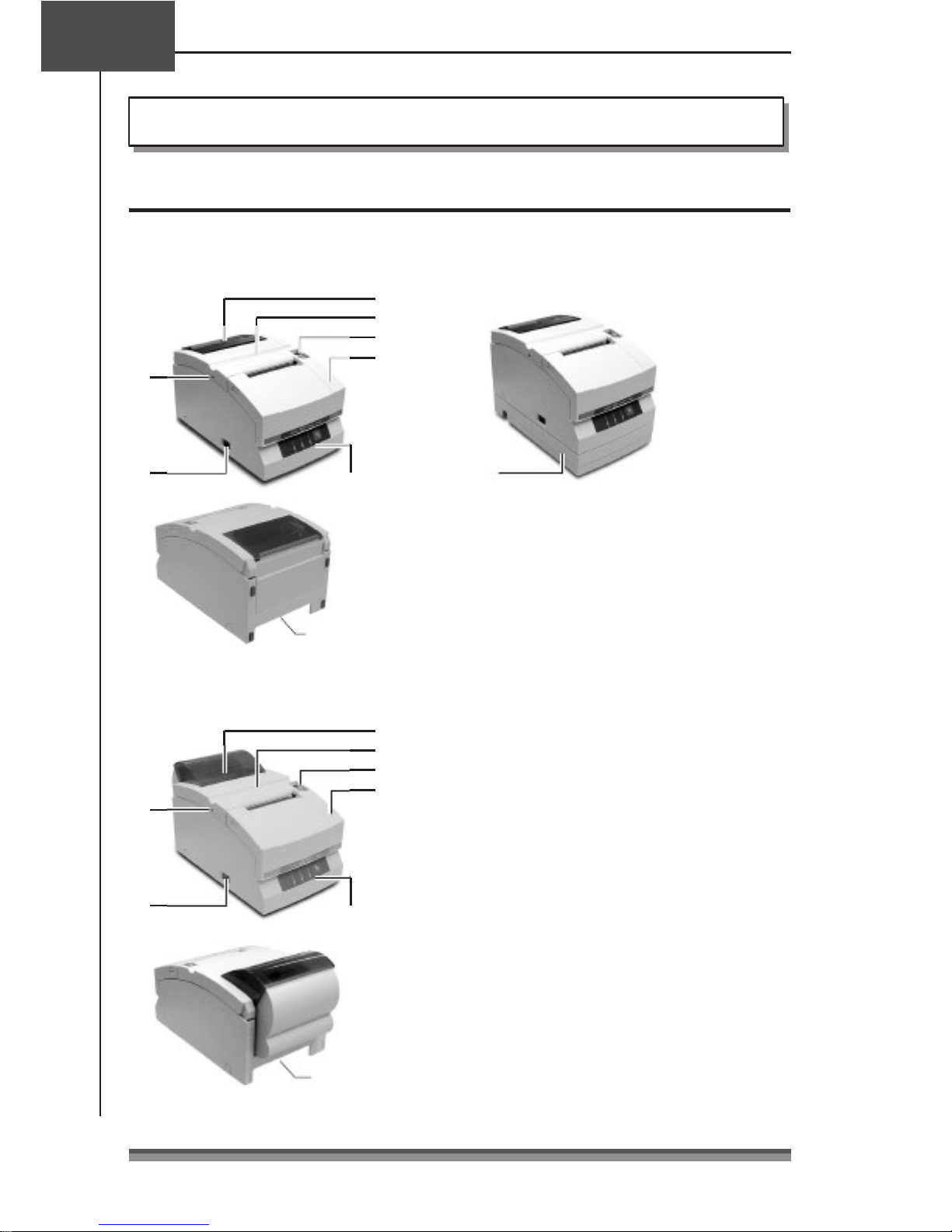
1 Paper check window
It can be used to check the amount of
paper left on the roll.
2 Rear cover
It can be opened to set or to replace a
paper roll.
3 Rear cover open lever
Auto cutter and rewinder equipped
Auto cutter and rewinder equippedAuto cutter and rewinder equipped
Auto cutter and rewinder equipped
model
modelmodel
model 1
2
It is a lever used to open the rear cover.
Pull the lever towards you to open the rear
cover.
6
5
3
4
Operation panel
(Refer Operational
Section)
Rear connectors
(Refer Rear
Connectors
Section)
4 Front cover
It can be opened to set or replace the
ribbon cassette.
5 Power switch
It turns the printer power on and off.
6 Cutter lock clearing screw hole
When the rear cover cannot be opened
because the blade of the auto cutter
protrudes after a malfunction or as a result
of a paper jam, turn this screw with a
Phillips head screw driver to return the
blade.
7 AC adapter case
This is installed only for the built-in AC adapter
type.
7777
Page 9
IIIInterior
nteriornterior
nterior
AC adapter type
AC adapter typeAC adapter type
AC adapter type
Standard and auto cutter equipped
Standard and auto cutter equippedStandard and auto cutter equipped
Standard and auto cutter equipped
model
modelmodel
model
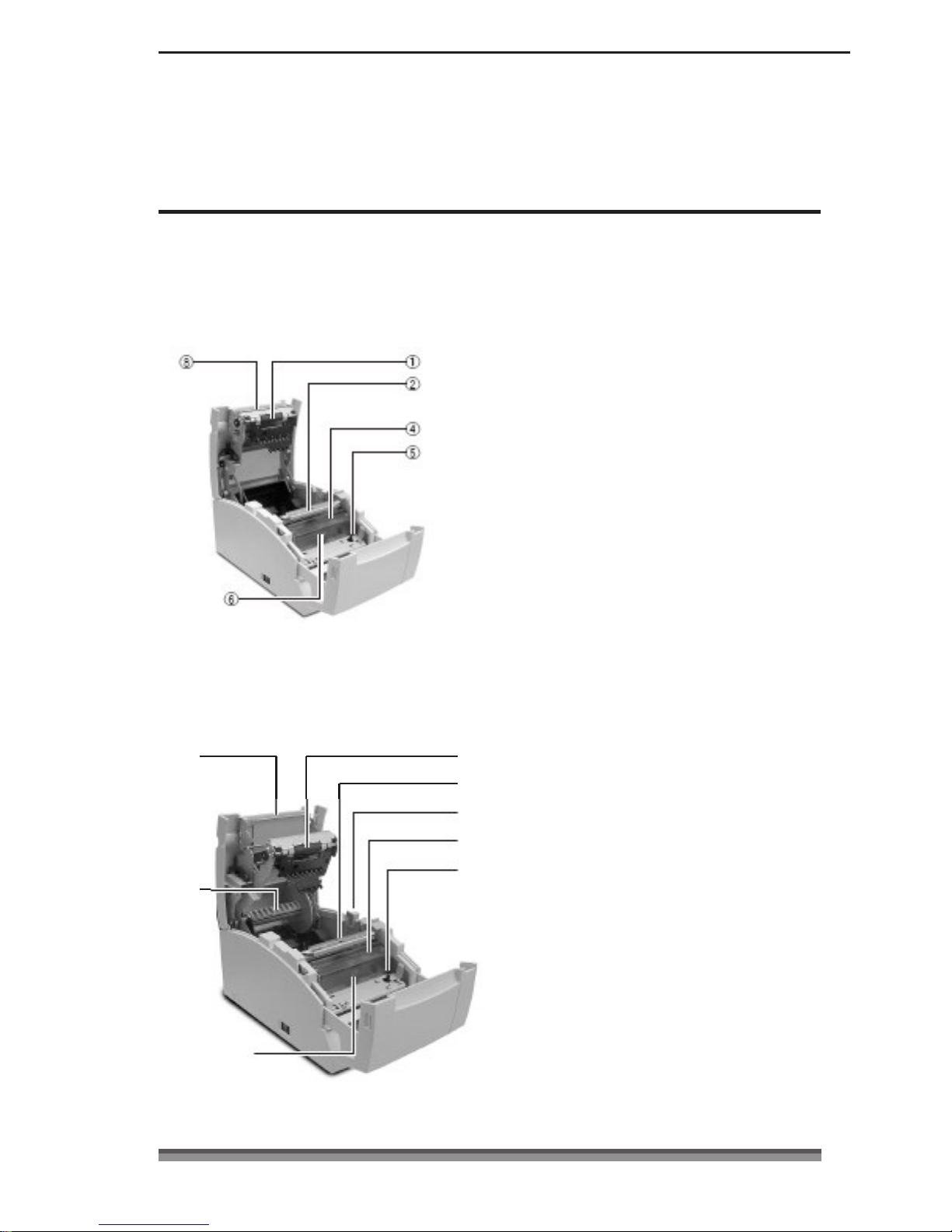
1 Platen unit
In the standard and auto cutter equipped
models, it is combined with 8 the auto
cutter.
2 Paper cut bar
It is used to cut the paper manually.
3 Platen open lever
It is a lever used to open the platen unit
on the rewinder equipped model. Open
the platen unit by pulling it towards you.
4 Print head cover
5 Ribbon cassette drive shaft
6 Print head
7 Rewinder shaft
Auto cutter and rewinder equipped
Auto cutter and rewinder equippedAuto cutter and rewinder equipped
Auto cutter and rewinder equipped
model
modelmodel
model
It rewinds the copy side of the copy roll
paper.
8
1
2
3
4
8 Auto cutter unit
It automatically cuts the paper after
printing is completed. The cut action is
set by a command in Soft SW Setting
Mode.
5
7
6
8888
Page 10

Chapter2
Chapter2Chapter2
Chapter2 Names and Functions of Parts
Operation Panel
Operation PanelOperation Panel
Operation Panel
5
1
2
3
4
1 POWER LED (Green)
It is lit when the power is supplied. When
maintenance mode is set or there is an
error indication, it is either lit or flashing.
2 PAPER OUT LED (Orange)
It is lit in paper out status. When
maintenance mode is set or there is an
error indication, it is either lit or flashing.
3 ERROR LED (Orange)
It is lit when the rear cover or front cover
is open. When maintenance mode is set
or there is an error indication, it is either
4 FEED Switch
When this switch is pressed once, paper
feeds (1 line). If it is held down, paper
feeds continuously until it is released.
And when there is a printer error, pressing
this switch can cancel the error status.
5 LED NAME SHEET
This sheet is used reversed according to
the printer installation method. See
Vertical Installation and Wall Mounted
Installation (page 23).
Display when installed horizontally
lit or flashing.
Display when installed vertically or
wall mounted
9999
Page 11
Rear Connectors
Rear ConnectorsRear Connectors
Rear Connectors
AC adapter type
AC adapter typeAC adapter type
AC adapter type
Parallel (IEEE1284) interface
Serial (RS232C) interface
Built
BuiltBuilt
Built----in AC adapter type
in AC adapter typein AC adapter type
in AC adapter type
1
2
3
4
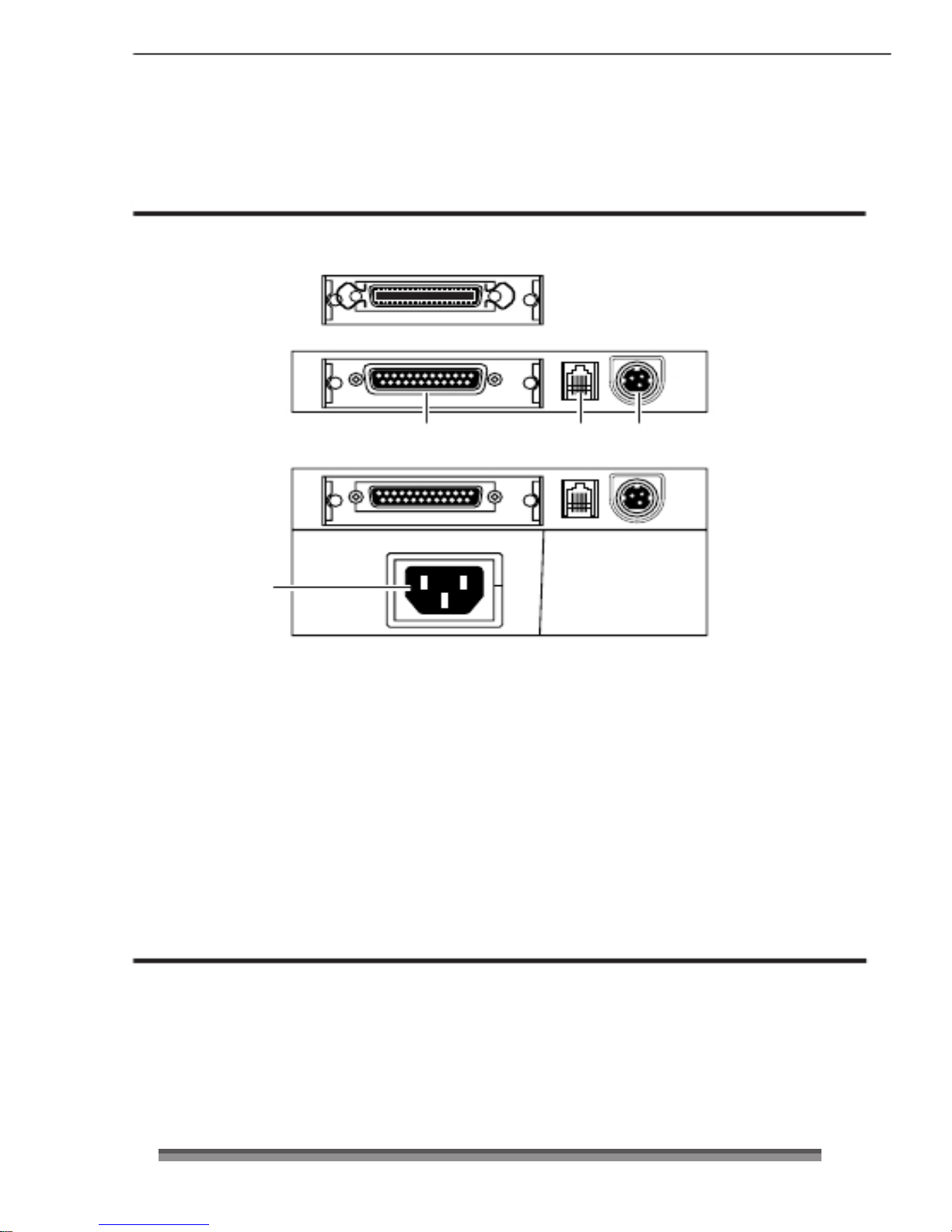
1 Interface connector
It is connected to either a serial (RS232C) or parallel (IEEE1284) interface cable.
* A USB interface replaced by a serial or parallel interface will be available as a factory
option.
2 Drawer kick connector
It is connected to a cable from the drawer.
3 Power source connector
It is connected to a cable from the AC adapter.
4 Power source inlet
It is connected to the power cord.
Others
OthersOthers
Others
Built
BuiltBuilt
Built----in Buzzer
in Buzzerin Buzzer
in Buzzer
A buzzer sounds when the FEED switch is operated and when there is an error.
The buzzer can be switched between enabled and disabled in Soft SW setting mode.
User Memory
User MemoryUser Memory
User Memory
Logo data or text data prepared by the user can be stored in memory.
This stored data remains in memory even after the power is turned off.
11110000
Page 12
Chapter3
Chapter3Chapter3
Chapter3
Preparing the Printer
Connections
ConnectionsConnections
Connections
Connecting the Interface Cable
Connecting the Interface CableConnecting the Interface Cable
Connecting the Interface Cable
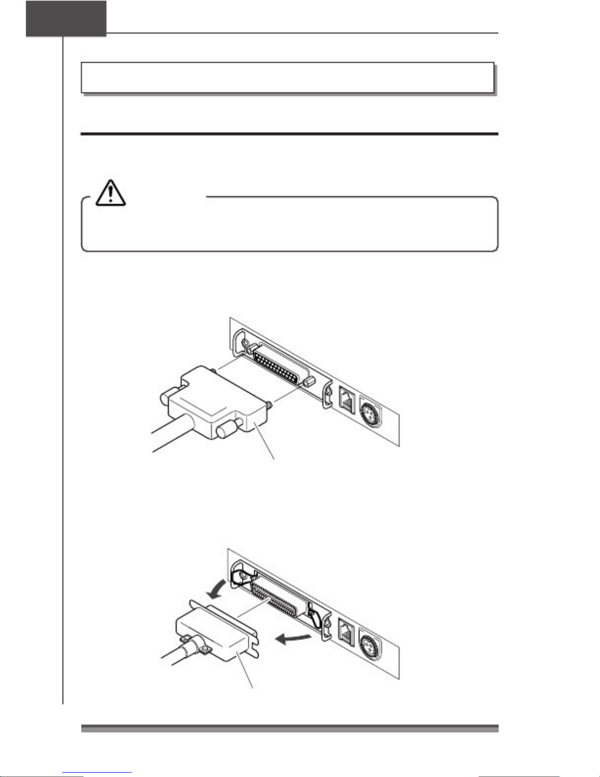
Turn off the power to the printer and insert the connectors being careful about their
orientation.
Caution
CautionCaution
Caution
Always hold the connector when pulling out a cable.
Install the interface cable so that it will not be caught on your shoes etc.
Connecting the serial (RS232C) interface cable
Connecting the serial (RS232C) interface cableConnecting the serial (RS232C) interface cable
Connecting the serial (RS232C) interface cable
Make sure that you insert it firmly and fix it in place by tightening the screw.
Serial (RS232C) interface cable
Connecting the
Connecting theConnecting the
Connecting the parallel (IEEE1284) interface cable
parallel (IEEE1284) interface cableparallel (IEEE1284) interface cable
parallel (IEEE1284) interface cable
Make sure that you insert it firmly and fix it in place by turning the attachment screws in
the direction shown by the arrow.
Parallel (IEEE1284) interface cable
11
1111
11
Page 13
Connecting the Drawer
Connecting the DrawerConnecting the Drawer
Connecting the Drawer
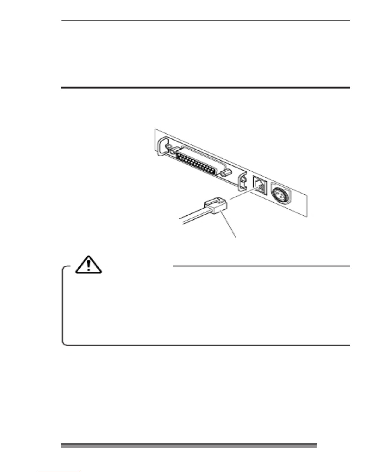
Match the top and bottom of the drawer kick connector with the cable terminal and insert
it firmly until you hear a click.
Drawer kick cable
Caution
CautionCaution
Caution
Connect only a specialized drawer. (Do not connect a telephone line.)
(Do not connect a telephone line.)(Do not connect a telephone line.)
(Do not connect a telephone line.)
Output is impossible during printing.
Drawer 1 and drawer 2 cannot be driven simultaneously.
Use a drawer use solenoid that is at least 24&. Make sure that the output current
is not higher than 1A. This may cause a malfunction or burn damage.
Install the drawer kick cable so that it will not be caught on your shoes etc.
12
1212
12
Page 14
Chapter3
Chapter3Chapter3
Chapter3
Preparing the Printer
Connecting the Power
Connecting the PowerConnecting the Power
Connecting the Power
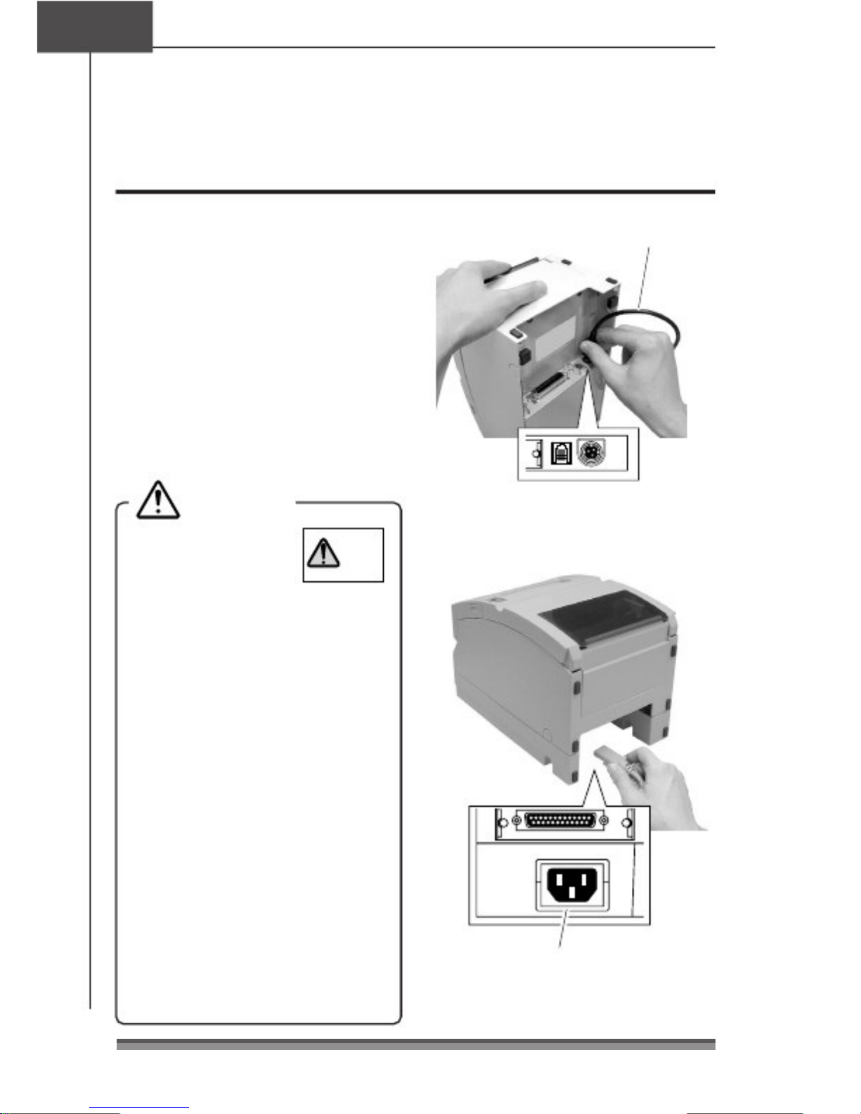
1. Make sure that the printer power
switch is set to OFF.
2. If your printer is an AC adapter type,
insert the AC adapter cable connector
with its flat side upwards into the
power connector on the rear surface
of the printer.
If your printer is a built-in AC adapter
type, insert the plug on the power
cord into the AC inlet on the back
surface of the printer.
Caution
CautionCaution
Caution
AC adapter cable
Flat side of the cable is up.
Do not use an AC
adapter other than
the stipulated product
DC 24V
51 AD
ONLY
AC adapter type
(Model 51AD).
Always hold the connector when
inserting or removing the cable
connector of the AC adapter.
Stretching the power cord by pulling
it will damage it, causing fire, electric
shocks, or a break in the conductor.
When lightening is striking nearby,
remove the plug of the power cord
from the outlet. Lightening will cause
fire or electric shock.
Do not place the power cord near a
heating device. The cover of the power
cord will melt, causing fire or electric
shock.
When the printer will not be used for
a long period, be sure to remove the
13
1313
13
plug of the power cord from the outlet
to guarantee safety.
Isolate the AC power source from
other devices that generate noise.
AC inlet
Built-in AC adapter type
Page 15
Horizontal
HorizontalHorizontal
Horizontal Vertical
VerticalVertical
Vertical Wall Mount
Wall MountWall Mount
Wall Mount
Standard model (AC adapter type) Yes No
2
Yes*
Standard model (Built-in AC adapter type)
Yes
1
Yes*
2
Yes*
Auto cutter equipped model (AC adapter type) Yes No
2
Yes*
Auto cutter equipped model (Built-in AC adapter type)
Yes
1
Yes*
2
Yes*
Auto cutter and rewinder equipped model
(AC adapter type)
Yes No No
Auto cutter and rewinder equipped model
(Built-in
AC adapter type)
Yes No No
Installation
InstallationInstallation
Installation
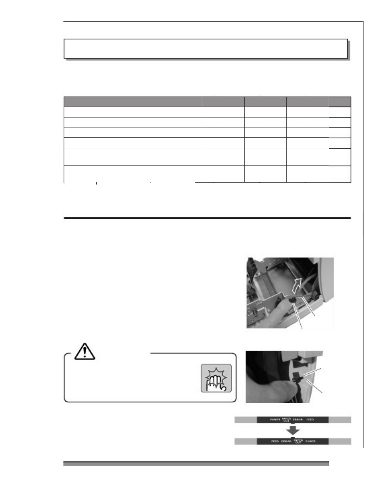
This printer can be installed horizontally or vertically and can be wall mounted.
But according to the model you are using, there may be restrictions on how it is installed.
Refer to the following table.
*1: Accessory rubber feet must be used to prevent slipping.
*2: The optional specialized wall mount unit is necessary to mount it on the wall.
Vertical installation and wall m
Vertical installation and wall mVertical installation and wall m
Vertical installation and wall mounted installation
ounted installationounted installation
ounted installation
To install the printer vertically or wall mounted, remove the Chassis Platen L Spring used
to
open the rear cover. And reverse the LED name sheet on the operation panel to use it with
the vertically installed and wall mounted display.
RRRRemoving the Chassis Platen L Spring
emoving the Chassis Platen L Springemoving the Chassis Platen L Spring
emoving the Chassis Platen L Spring
1
. Open the rear cover. Do this carefully, because
the cover snaps open vigorously.
2
. Lift part A with the fingers of your right hand.
3
. Switch the Chassis Platen L Spring that you have
raised from your right thumb to your left thumb
to hook the protrusion on the end of the Chassis
Platen L Spring inside part B of the printer.
Caution
CautionCaution
Caution
Chassis Platen L Spring with strong
repulsive force is used. Be very careful
that it does not slip off your finger
causing an injury.
Chassis Platen
L Spring
Part A
Protrusion
Part B
LED Name Sheet
LED Name SheetLED Name Sheet
LED Name Sheet
Remove and reverse the sheet then reinsert the
protruding part of the center of the sheet in the
printer and push in both ends.
14
1414
14
Page 16
Remaining roll
paper (mm)
Sensor location
Horizontal
Approx. 22
1
Approx. 24
2
Approx. 27
3
Vertical
(wall mounted)
Approx. 27 4
Approx. 24 5
Approx. 22
6
Chapter3
Chapter3Chapter3
Chapter3
Preparing the Printer
Setting t
Setting tSetting t
Setting the Paper Near End Sensor
he Paper Near End Sensorhe Paper Near End Sensor
he Paper Near End Sensor
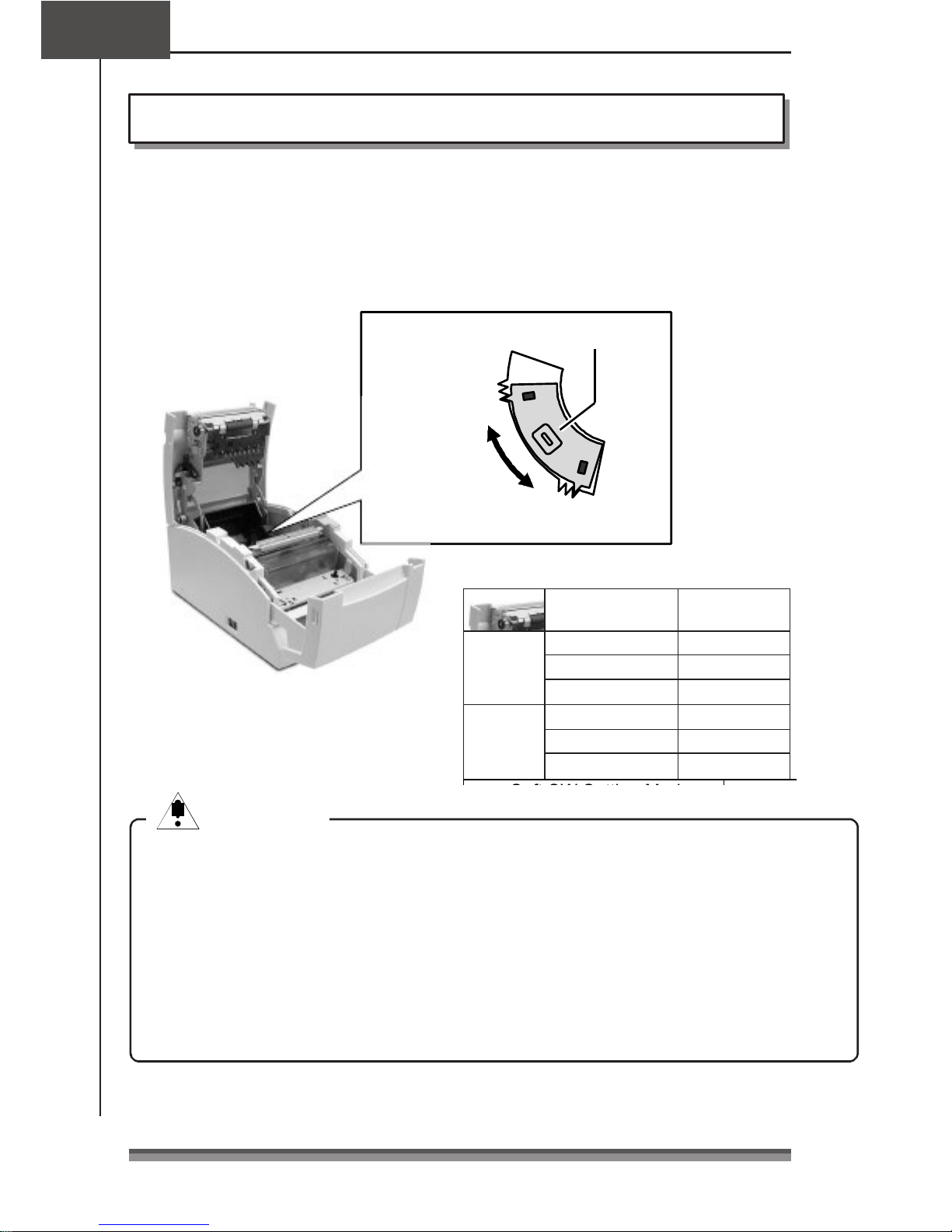
Change the sensor location according to the way the printer is installed and the interior
diameter of the roll paper you are using. Referring to the following table, set it at a
location suited to the usage environment by moving it to the left and right while pushing
the concave part of the center of the sensor with your finger. (When shipped from the
factory, it is set at 24mm.)
Paper near end sensor
When installed
vertically and
wall hung
6
5
4
3 2
1
When installed horizontally
Caution
CautionCaution
Caution
The remaining roll paper (external diameter of the roll paper) differs greatly
according to the type of roll paper used. Use these values only as guidelines.
When the sensor has detected the remaining roll paper during printing, the printer
stops printing after it has printed all the data that it had received.
If you are using a model with parallel (IEEE1284) interface specifications, you can
select sensor enabled/disabled in Soft SW Setting Mode.
If you are using a model with serial (RS232C) interface specifications, it is always
enabled.
15
1515
15
Page 17
Installation
method
Remaining roll
paper (mm)
Sensor location
Horizontal
Approx. 22
1
Approx. 24
2
Approx. 27
3
Vertical
Approx. 27 4
Approx. 24 5
Setting the Paper Width and Printing Line Column Number
Setting the Paper Width and Printing Line Column NumberSetting the Paper Width and Printing Line Column Number
Setting the Paper Width and Printing Line Column Number
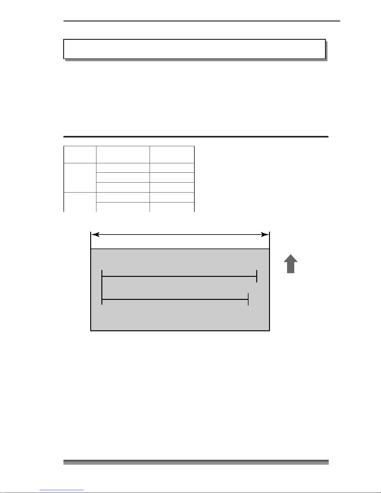
The printing dot line columns are changed as follows by setting the “ Paper Width” of the
roll paper used, the “ Number of col.” and the “ Font Select” in Soft SW Setting Mode.
For details about setting, see Soft SW Setting Mode (page 35).
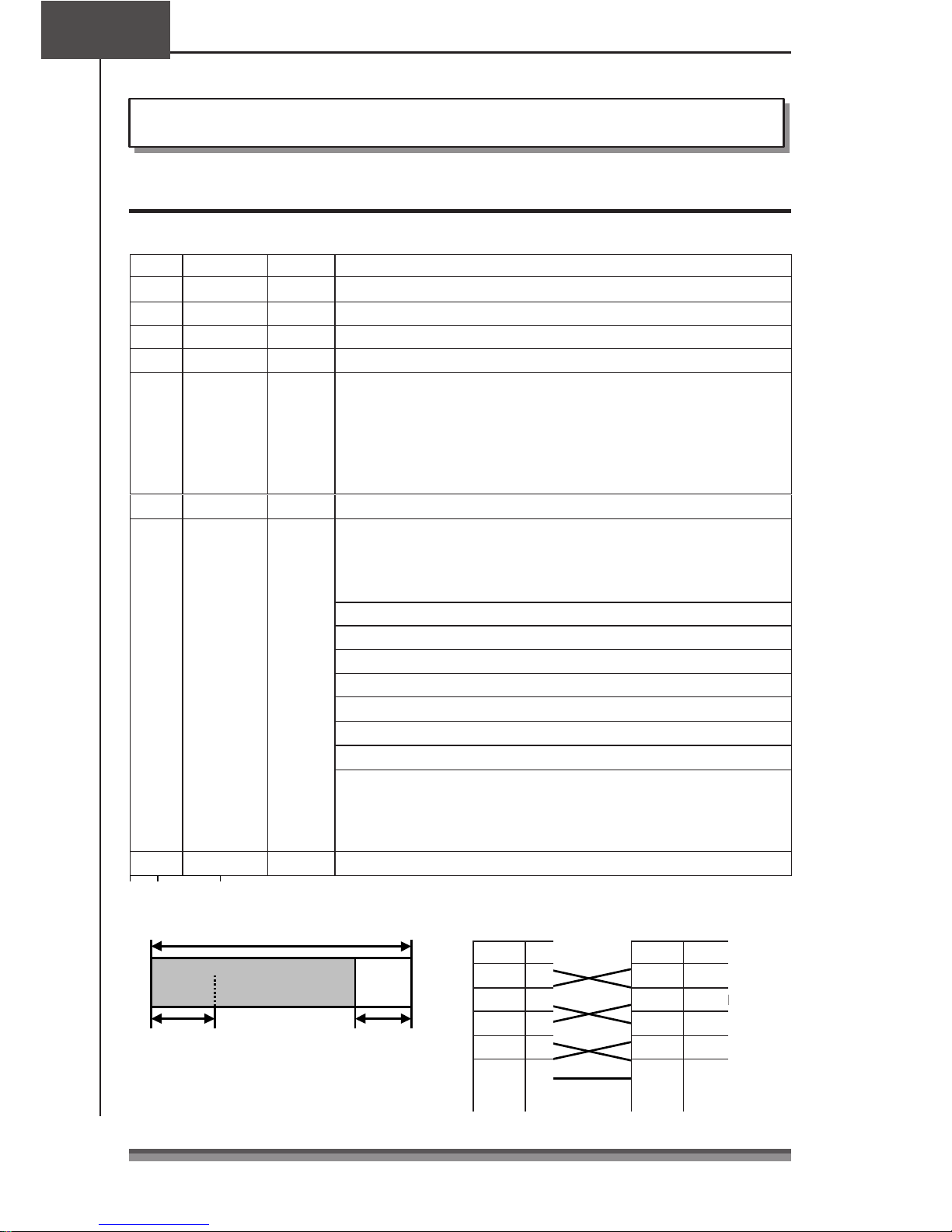
When setting Paper Width of 76.2mm
When setting Paper Width of 76.2mmWhen setting Paper Width of 76.2mm
When setting Paper Width of 76.2mm
Paper width: 76.2mm
When Number of col. 40/33 are selected: 400 dots
Paper feed
When Number of col. 42/35 are selected: 386 dots
direction
16
1616
16
Page 18
Installation
method
Remaining roll
paper (mm)
Sensor location
Horizontal
Approx. 22
1
Approx. 24
2
Approx. 27
3
Vertical
Approx. 27 4
Approx. 24 5
Installation
method
Remaining roll
paper (mm)
Sensor location
Horizontal
Approx. 22
1
Approx. 24
2
Approx. 27
3
Vertical
Approx. 27 4
Approx. 24 5
Chapter3
Chapter3Chapter3
Chapter3
Preparing the Printer
Setting Paper Width and Printing Line Columns
Setting Paper Width and Printing Line ColumnsSetting Paper Width and Printing Line Columns
Setting Paper Width and Printing Line Columns
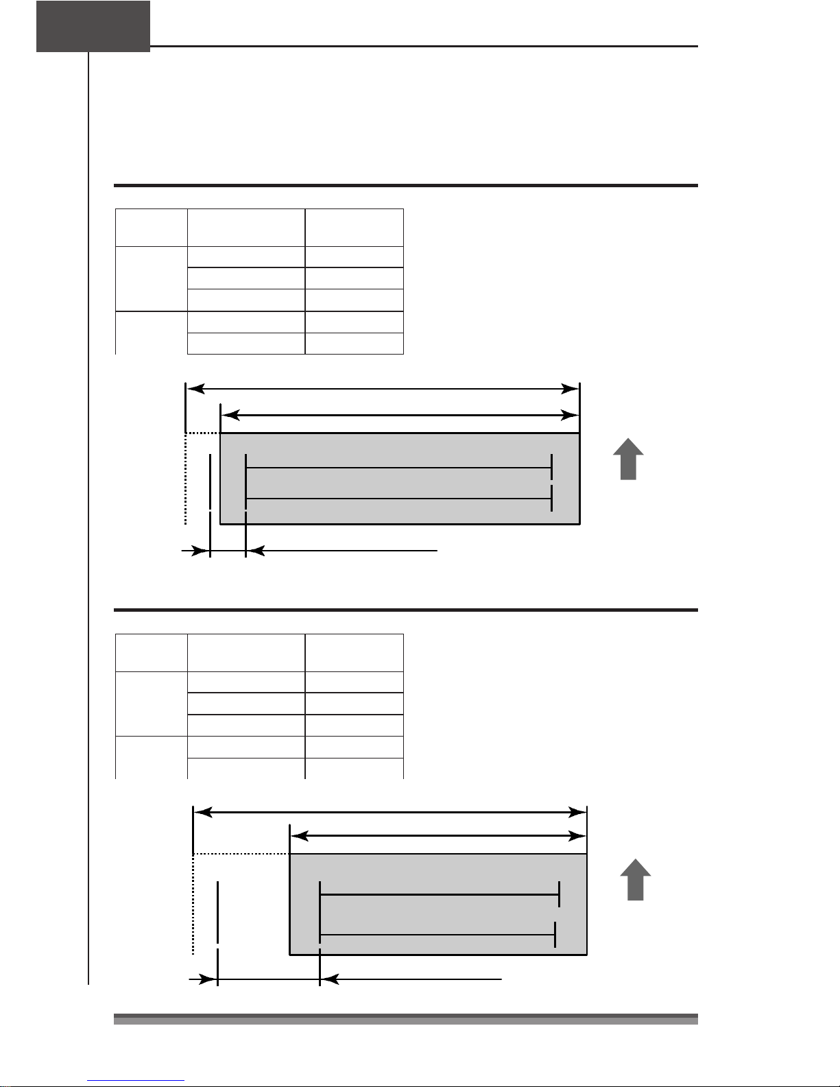
When setting Paper Width of 69.5mm
When setting Paper Width of 69.5mmWhen setting Paper Width of 69.5mm
When setting Paper Width of 69.5mm
Paper width: 76.2mm
Paper width: 69.5mm
When Number of col. 40/33 are selected: 360 dots
When Number of col. 42/35 are selected: 360 dots
Paper feed
direction
Right offset: 40 dots
When setting Paper Width of 57.5mm
When setting Paper Width of 57.5mmWhen setting Paper Width of 57.5mm
When setting Paper Width of 57.5mm
Paper width: 76.2mm
Paper width: 57.5mm
When Number of col. 40/33 are
selected: 300 dots
17
1717
17
When Number of col. 42/35 are
selected: 298 dots
Right offset: 100 dots
Paper feed
direction
Page 19
Installing the R
Installing the RInstalling the R
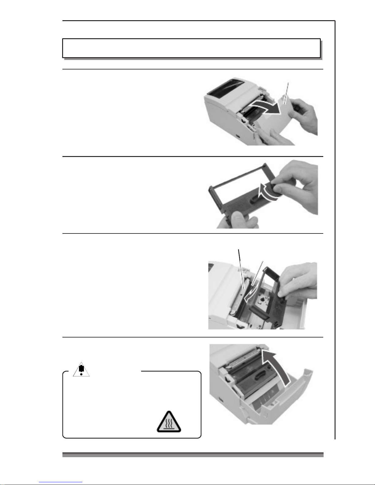
Installing the Ribbon Cassette
ibbon Cassetteibbon Cassette
ibbon Cassette
1. Open the front cover of the printer.
Insert your fingers into the dents at
opposite ends of the front cover to
open it with both hands.
2. Turn the ribbon cassette knob in the
direction shown by the arrow to fully
stretch the ribbon.
3. Insert the cassette into the printer
until a click is heard so that the ribbon
Paper cut bar
Front cover
Print head cover
is between the paper cut bar and the
print head cover. If it difficult to insert,
turn the ribbon cassette knob again.
4. Close the front cover.
Caution
CautionCaution
Caution
Be very careful not to let your hands
touch the print head cover when
replacing the ribbon cassette. When the
print head has become
heated, there is a danger of
it burning your hand.
18
1818
18
Page 20
Core diameter: Interior diameter
10
– 0
mm, exterior diameter
27mm or less
Chapter3
Chapter3Chapter3
Chapter3
Preparing the Printer
Installing Roll Paper
Installing Roll PaperInstalling Roll Paper
Installing Roll Paper
The following are the types of roll paper that can be used by this printer.
Types: 1P roll paper
2P copy roll paper (1 original + 1 copy)
3P copy roll paper (1 original + 2 copies)
(2P and 3P copy roll paper are only usable on models equipped with auto
cutter and rewinder.)
Paper widths: 76.2 (±0.7)/69.5 (±0.6)/57.5 (±0.5)mm
Roll diameter: 30mm to 83mm
+2
Paper thickness: 1P 0.06 to 0.085mm
Copy paper 0.05 to 0.20mm (total thickness)
But the total thickness that can be cut is from 0.05 to 0.14mm.
Standard and Auto Cutter Equipped Models
Standard and Auto Cutter Equipped ModelsStandard and Auto Cutter Equipped Models
Standard and Auto Cutter Equipped Models
Inst
InstInst
Installation method
allation methodallation method
allation method
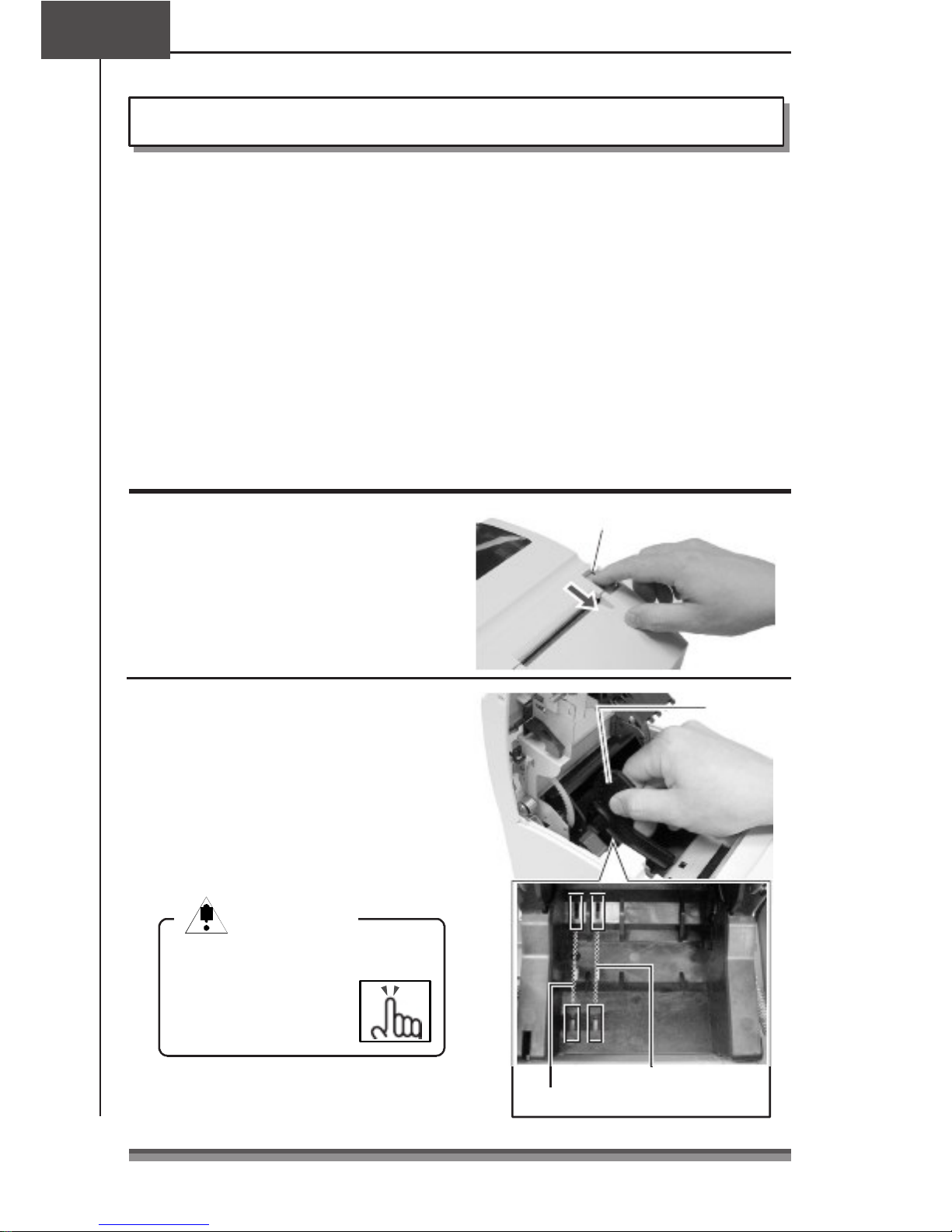
1. Pull the rear cover open lever towards
you to open the rear cover.
2. Set the attached partition in place if
Rear cover open lever
Partition
the roll paper you are using is 69.5mm
wide or 57.5mm wide.
Change the paper width by changing
the value set as the width using the
Soft SW Setting Mode.
(See page 35)
Caution
CautionCaution
Caution
When setting the roll paper, be
careful not to cut your
hand on the edge of
the paper.
Location set for width of 57.5mm
Location set for width of 69.5mm
19
1919
19
Page 21
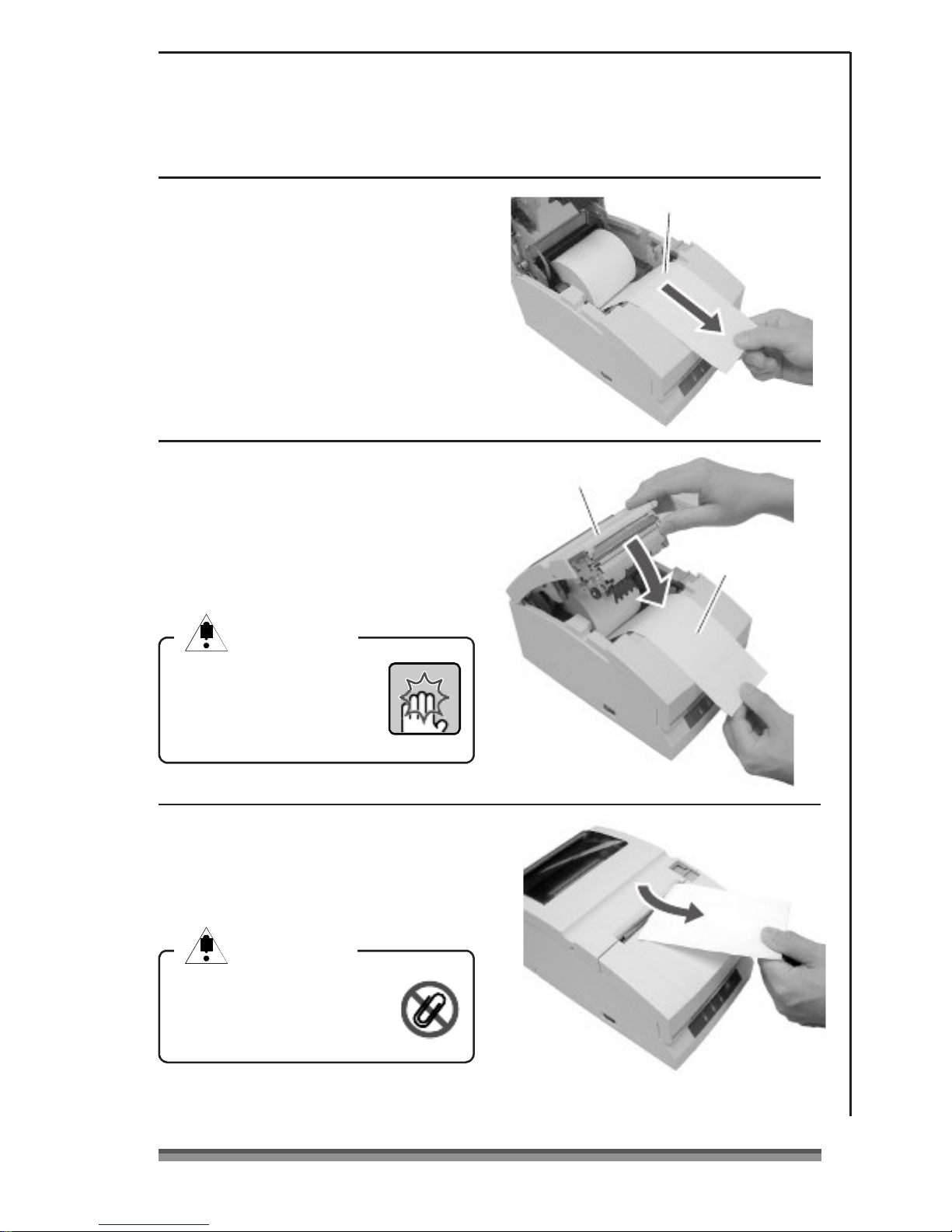
3. Place the roll paper and pull the end
of the roll paper directly towards you
as shown in the figure.
Hold the center of the roll paper to pull
it as straight as possible so that one of
the sides of the paper does not slacken.
4. Maintaining tension in the roll paper,
firmly close the rear cover until you
hear a click.
Paper feeds automatically and stops
Rear cover
1P roll paper
Roll paper that is
gently pulled taut.
at the print start position.
Caution
CautionCaution
Caution
Be very careful not to let
the rear cover catch your
hands when closing the rear
cover.
5. Tear off surplus paper by holding one
side of the end of the roll paper and
pulling it towards you.
Caution
CautionCaution
Caution
Do not insert any foreign
objects such as a paper clip
into the cutter unit.
20
2020
20
Page 22
Chapter3
Chapter3Chapter3
Chapter3
Preparing the Printer
Installing Roll Paper
Installing Roll PaperInstalling Roll Paper
Installing Roll Paper
Auto Cutter and Rewinder Equipped Model
Auto Cutter and Rewinder Equipped ModelAuto Cutter and Rewinder Equipped Model
Auto Cutter and Rewinder Equipped Model
Installation Method
Installation MethodInstallation Method
Installation Method
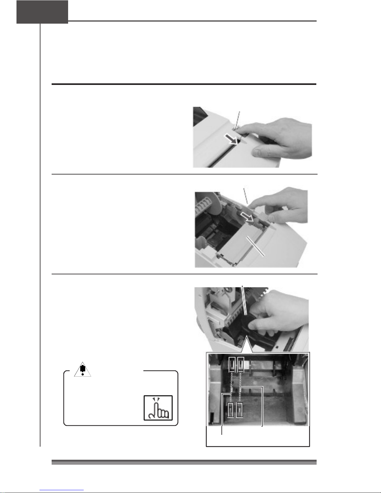
1. Pull the rear cover open lever towards
you to open the rear cover.
2. Then pull the platen open lever
Rear cover open lever
Platen open lever
towards you to open the platen unit.
Platen unit
3. Set the attached partition in place if
Partition
the copy roll paper you are using is
69.5mm wide or 57.5mm wide.
Change the paper width by changing
the value set as the width using the
Soft SW Setting Mode.
(See page 35)
Caution
CautionCaution
Caution
When setting the roll paper, be
careful not to cut your
hand on the edge of
the paper.
Location set for width of 57.5mm
Location set for width of 69.5mm
21
2121
21
Page 23
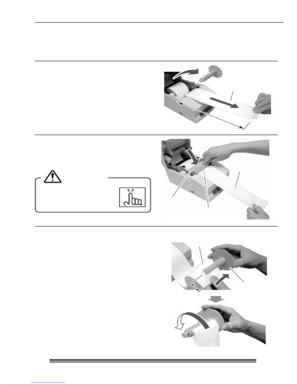
4. After removing the rewinder shaft,
install the copy roll paper and pull the
end of the roll paper straight towards
you for about 30cm as shown in the
figure.
Hold the center of the roll paper to pull it
as straight as possible so that one of the
sides of the paper does not slacken.
5. Maintaining light tension in the copy
roll paper, firmly close the platen unit
until you hear a click.
Rewinder shaft
2P or 3P copy roll paper
About 30cm
Roll paper that is
gently pulled taut.
Caution
CautionCaution
Caution
Be very careful not to let
your hands touch the blade
on the paper cutter bar.
6
. Set one side of the copy roll paper
(copy side) on the rewinder shaft as
shown in the figure, and tightly wind
it about 2 rotations in the direction
shown by the arrow.
Check to make sure that the copy roll
paper rotates with the rewinder shaft.
Platen unit
Be careful of the paper cut bar.
Copy roll paper
(copy side)
Rewinder shaft
Protrudes
about 5cm
Wind it about twice
22
2222
22
Page 24
Chapter3
Chapter3Chapter3
Chapter3
Preparing the Printer
Installing roll paper
Installing roll paperInstalling roll paper
Installing roll paper
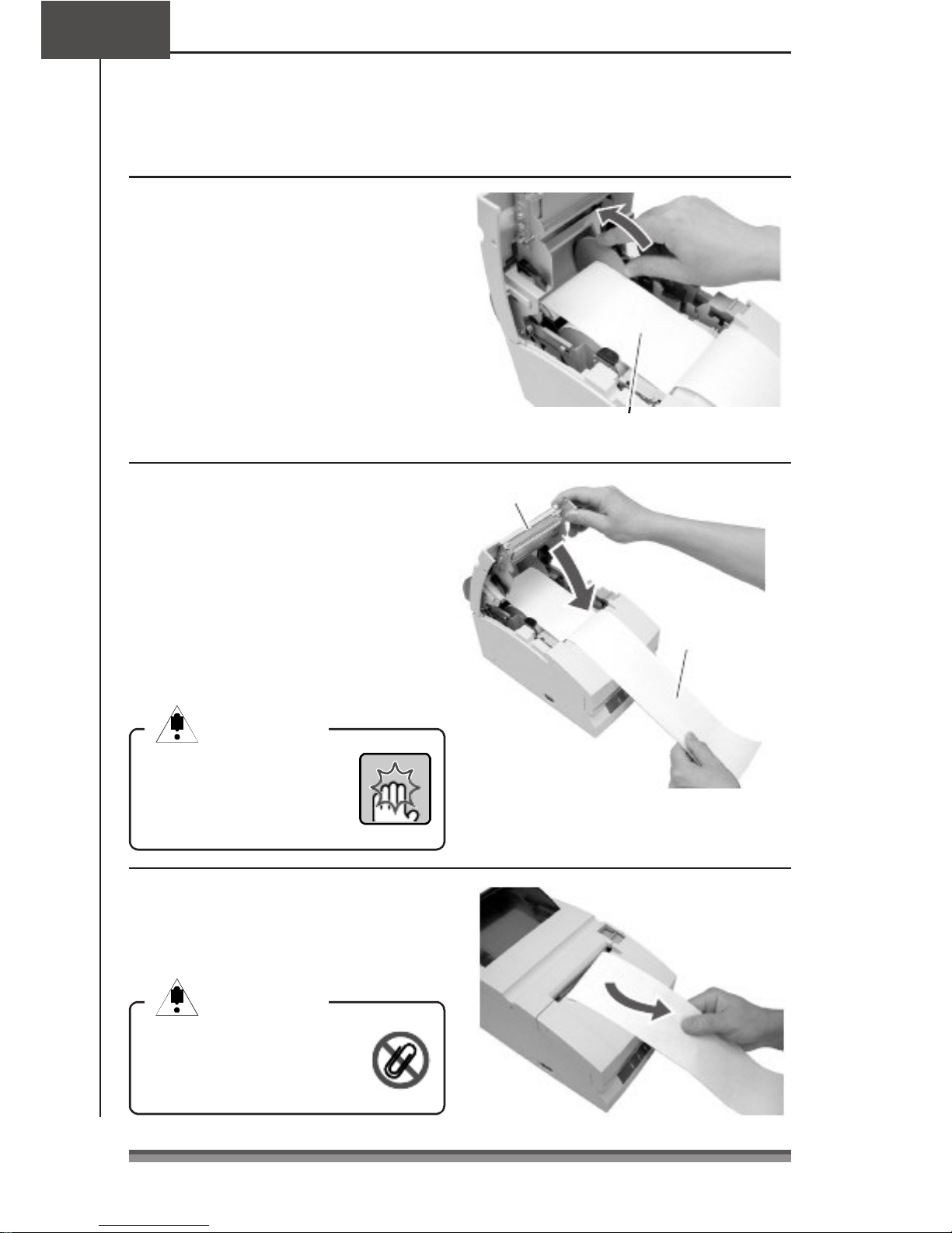
7. Being careful not to let the copy roll
paper set on the rewinder shaft
slacken, place the roll paper in the
grooves on both sides.
Turn the flange on the rewinder shaft
in the direction shown by the arrow
and make sure that the copy roll
paper rotates with the rewinder shaft.
Taking up slack while checking that
the copy roll paper winds.
23
2323
23
8. With the other side of the copy roll
paper (original side) pulled lightly
taut, close the rear cover firmly until
you hear a click.
Hold the center of the roll paper to pull
it as straight as possible so that one of
the sides of the paper does not slacken.
Paper feeds automatically and stops
at the print start position.
Caution
CautionCaution
Caution
Be very careful not to let
the rear cover catch your
hands when closing the rear
cover.
9. Tear off surplus paper by holding one
side of the end of the roll paper and
pulling it towards you.
Caution
CautionCaution
Caution
Do not insert any foreign
objects such as a paper clip
into the cutter unit.
Rear cover
Roll paper that is
gently pulled taut.
Page 25
Operation when the cover is opened and closed
Operation when the cover is opened and closedOperation when the cover is opened and closed
Operation when the cover is opened and closed
Operation when the front cover is opened and closed
Operation when the front cover is opened and closedOperation when the front cover is opened and closed
Operation when the front cover is opened and closed
Opening: During printing, the printing stops and if it is in red printing status, the ribbon
is switched to the black ribbon status, moves to the centering location, and
becomes the condition you can replace the ribbon cassette.
Closing: If it was red printing status when it was opened, the ribbon returns to red status
and if there is printing data, printing restarts.
Operation when the rear cover is opened and closed
Operation when the rear cover is opened and closedOperation when the rear cover is opened and closed
Operation when the rear cover is opened and closed
Opening: During printing, the printing stops and the ribbon moves to the centering
location and remains in stand by. On models equipped with a rewinder, if the
cover is opened with paper set, the paper is fed forward about 1 inch then
returns to the centering position.
Closing: After print operation and cut operation have been initialized, it performs paper
feed check, and if there is printing data, printing restarts.
Caution
CautionCaution
Caution
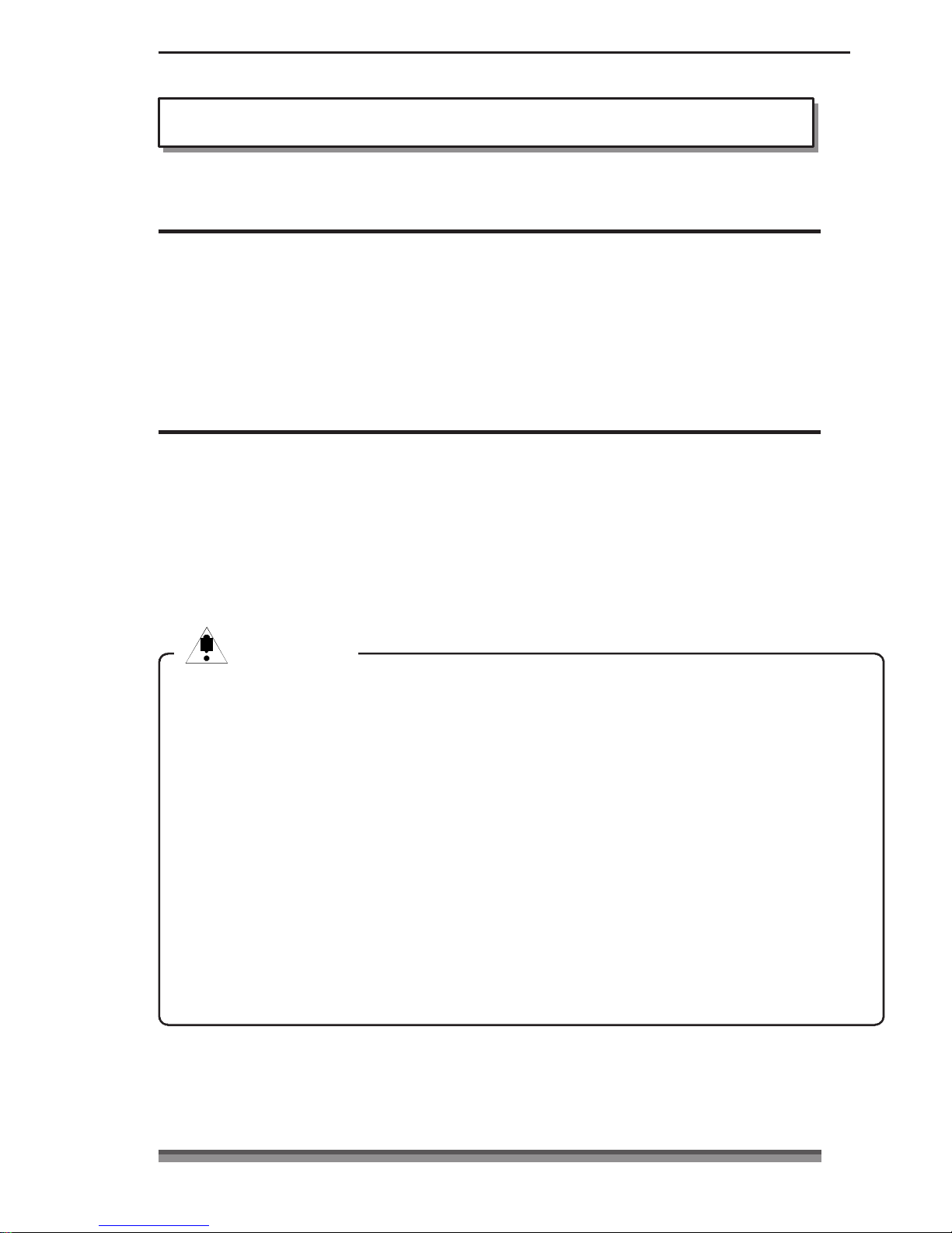
If a cutter problem is caused by a paper jam etc., the printer may stop with the
cutter blade protruding so that the rear cover cannot be opened. In this case,
press the FEED switch to eliminate the cutter problem without trying to force it
open. If the problem is not eliminated by pressing the switch, insert a screw driver
in the hole on the left side surface of the rear cover and rotate it to manually
restore the cutter blade, then open the cover. (The blade will be restored by turning
it to either the left or the right.)
Be careful of the manual paper cut bar in particular, to make sure that your fingers
are not caught when opening and closing the cover.
Opening the rear cover during printing causes malfunctions of the printer head or
cutter unit. Make sure that printing has stopped before you open the rear cover.
To close the rear cover, close it while holding the end of the paper so that the
paper is not slack or bent inside the printer.
24
2424
24
Page 26
Chapter4
Chapter4Chapter4
Chapter4
Maintenance Mode
Maintenance Mode
Maintenance ModeMaintenance Mode
Maintenance Mode
The settings of the printer can be changed according to its usage environment in
maintenance mode. And it is also possible to change their settings back to the initial
factory shipping setting or to adjust the cut position after printing in this mode.
And the content of the settings can be confirmed in demonstration printing mode.
To change the settings in maintenance mode, print and check the present settings.
Demonstration printing mode
Demonstration printing modeDemonstration printing mode
Demonstration printing mode
Setting the mode
Setting the modeSetting the mode
Setting the mode
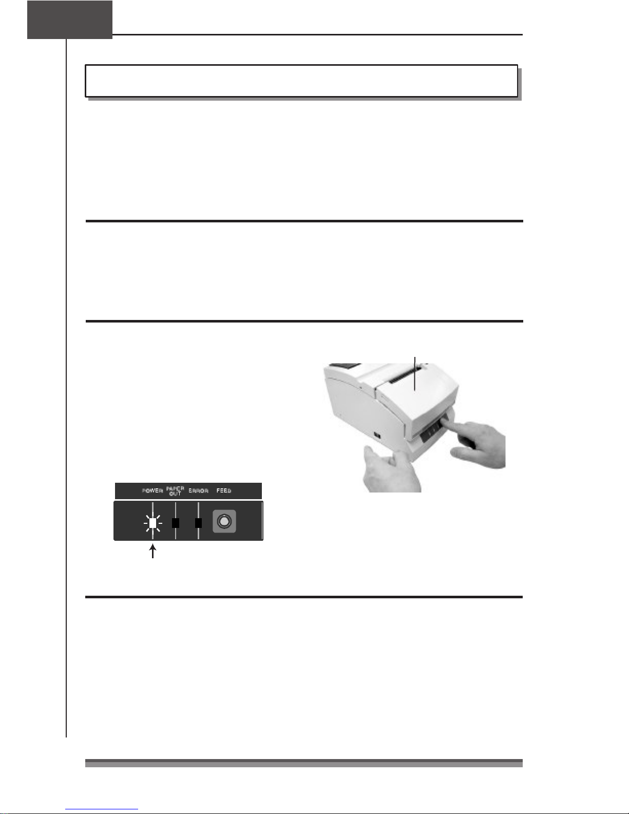
Turning the power on while pressing the FEED switch with the front cover and the rear
cover both closed starts demonstration printing mode and the “ demonstration printing
and the present printing settings” are printed.
Setting maintenance mode
Setting maintenance modeSetting maintenance mode
Setting maintenance mode
1
. Set maintenance mode by turning on
the power while pressing the FEED
switch with the front cover open and
the rear cover closed, then releasing
the FEED switch.
2
. The POWER LED flashes as the printer
enters maintenance mode.
Power switch
Front cover open
FEED switch
Close the front cover in this status.
Flashing
Types of maintenance mode
Types of maintenance modeTypes of maintenance mode
Types of maintenance mode
There are the following four types of maintenance mode.
Each mode is selected according to the number of times the FEED switch is pressed from
maintenance mode.
HEX Dump Mode: Press the FEED switch 0 times and reopen and close the front cover.
Soft SW Setting Mode: Press the FEED switch 1 time and reopen and close the front cover.
Initial Factory Shipping Mode: Press the FEED switch 2 times and reopen and close
the front cover.
Cut Position Adjustment Mode: Press the FEED switch 3 times and reopen and close
the front cover.
25
2525
25
Page 27
HEX Dump Mode
HEX Dump ModeHEX Dump Mode
HEX Dump Mode
Setting the mode
Setting the modeSetting the mode
Setting the mode
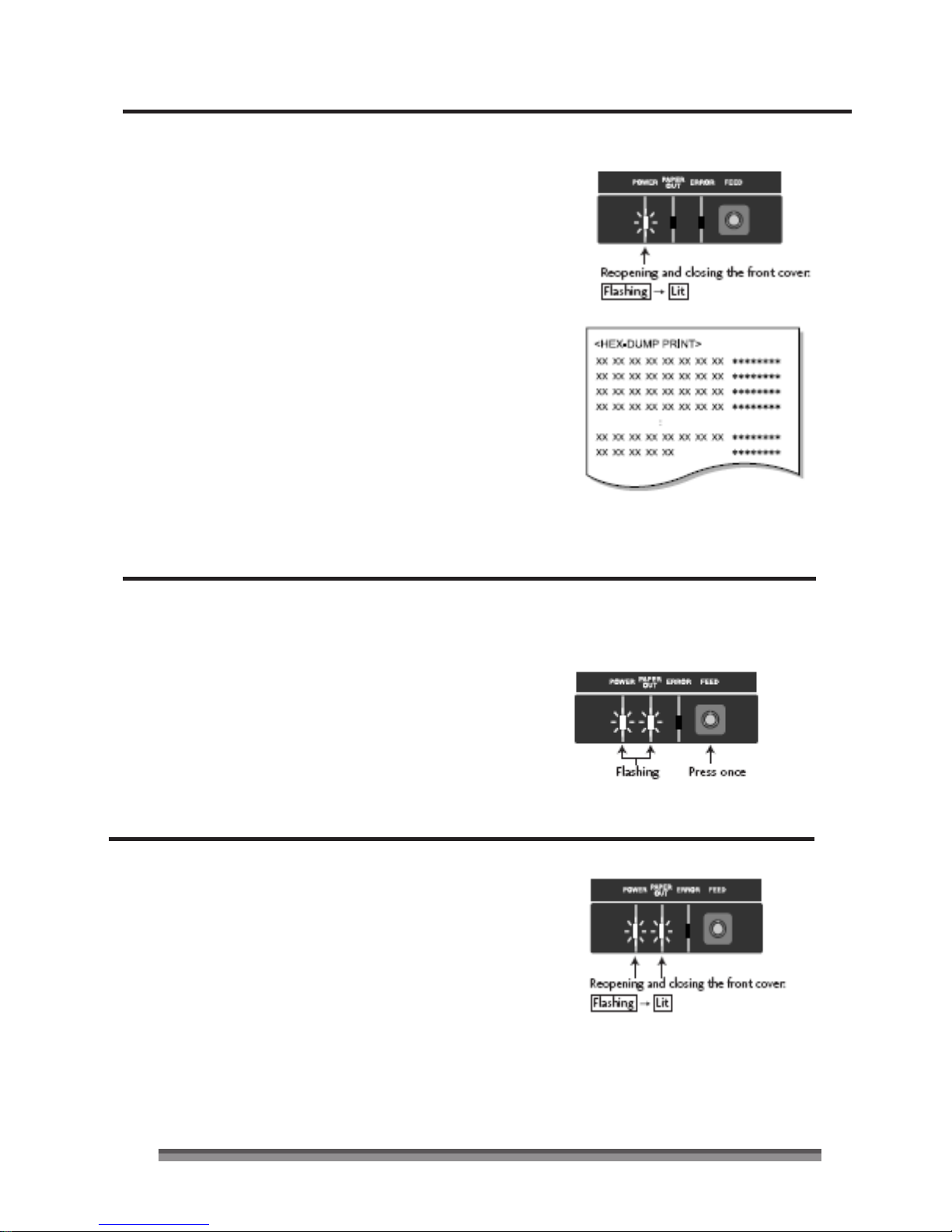
If the front cover is reopened and closed
in maintenance mode (POWER LED is
flashing), the POWER LED stops flashing
and remains lit, and the printer enters
HEX Dump Mode.
After printing the title, it stands by to
receive data.
To leave HEX Dump Mode, turn off the
printer power then turn the power on again
with the front and rear covers both closed.
Soft SW Setting Mode
Soft SW Setting ModeSoft SW Setting Mode
Soft SW Setting Mode
Setting the mode
Setting the modeSetting the mode
Setting the mode
1. If the FEED switch is pressed once in
maintenance mode (POWER LED is
flashing), the POWER LED and PAPER
OUT LED start flashing.
2. If the front cover is reopened and
closed in this status, the POWER LED
and PAPER OUT LED stop flashing to
and remain lit, and after the title and
top items have printed, it enters Soft
SW Setting Mode.
26
2626
26
Page 28
Chapter4
Chapter4Chapter4
Chapter4
Maintenance Mode
Soft SW Setting Mode
Soft SW Setting ModeSoft SW Setting Mode
Soft SW Setting Mode
Operating method
Operating methodOperating method
Operating method
Press the FEED switch (less than 2 seconds):
The setting changes.
The present set value is changed and the
same item is reprinted. (Press the FEED
switch, and when the buzzer sounds once,
release it.)
Pressing the FEED switch continuously (2
seconds or more):
Moves to the next item.
It prints the present set value of the next
item. (Press the FEED switch, and when the
buzzer sounds three times, release it.)
Opening/closing the front cover:
After saving the set values, it reprints all
items from the top and returns to normal
power on status.
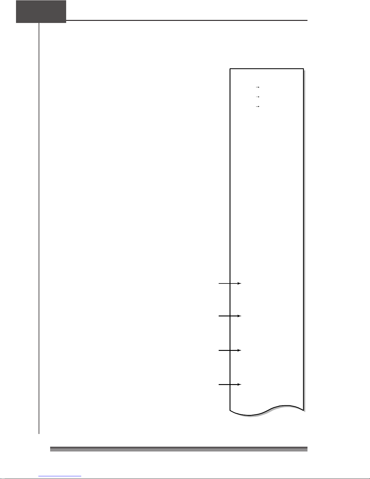
<Soft-Swit ch Setting>
Press Feed
Change PA RM.
Press Feed For 2S
Next Item
F.Cover Open/Close
Save & Ex it
<Soft Con trol-SW>----- ---------------
Command Type –EPS ON
Number o f Col. –40/33
Font Sel ect –7 ⋅ 9
Paper Plies –OFF
Paper End –ENB
Paper Ne ar-End –ENB
Slashed Ze ro – OFF
Print Direc t. –BI-DIR
Auto LF –OFF
Code Page –437
Buffer Size –4K
Init Signal –ENB
Buzzer –ON
<Interface -SW>-------- ----------------
Baud Ra te –9600
Data Lengt h –8bit
Parity Bi t –NONE
Stop Bit –1bit
Protocol –DTR
<Mechanica l-SW>------ --------------
Paper Wid th –76.2
Auto-Cutt er –PAR.
Color Ribb on –O N
Take-Up Device –ON
Black Mark –DIS
* If the power is turned off without opening
and closing the front cover, the setting
change is invalid.
* If the paper runs out during the change,
Operations
Press the
FEED Switch
Command Type
Command Type
–EPSO N
–STAR
set the paper and close the rear cover to
continue the process.
Press and
hold the FEED
Switch
Press and
hold the FEED
Switch
Press the
FEED Switch
Number o f Col.
Font Sel ect
Font Sel ect
–40/33
–7 ⋅ 9
–9 ⋅ 9
Example of a change of the Command Type to
STAR and the Font Select to 9⋅9.
27
2727
27
Page 29

Setting Mode Table
Setting Mode TableSetting Mode Table
Setting Mode Table
Soft Control
Soft ControlSoft Control
Soft Control----SW
SWSW
SW
Set item
Command Type
Initial value
EPSON
Setting value
EPSON
STAR
Remarks
The emulation is selected from EPSON/STAR/
CBM1/CBM2.
CBM1
CBM2
Number of Col. 40/33 40/33
42/35
Number of full dot in full column is 200 dots. For the
number of line columns based on the paper width, see
“ Setting the Paper Width and Printing Line Column Number” .
Font Select
Paper Plies
Paper End
7x9
OFF
ENB
7Ω 9
9Ω 9
OFF
2P
3P
ENB
DIS
The initial font size is selected immediately after the
power is turned on.
Copy mode is selected.
OFF/2P/3P can be selected. But when 3P is set, the
printing speed is low.
The PE signal enabled/disabled is set at paper end when
only the centro-interface is set as enabled. During
enabled status, BUSY, PE, FAULT are output and printing
stops at paper out. During disabled status, only BUSY is
output and printing stops at paper out.
Paper Near-End
ENB ENB
DIS
The PE signal enabled/disabled is set at paper near end
when only the centro-interface is set as enabled. During
enabled status, PE, FAULT are output and printing
continues. During disabled status, nothing is output and
printing continues.
Slashed Zero
Print Direct.
OFF
BI-DIR
OFF
ON
BI-DIR
UNI-DIR
It sets whether or not slash is used with the numeral 0
(zero).
Designates printing direction. When BI-DIR is selected,
printing starts from the closer of the left and right ends
of the next printing line from the print stop location.
During UNI-DIR printing is usually done from the left end.
Auto LF OFF OFF
ON
The LF operation during CR code reception is selected.
When ON, LF does not operate; when OFF, LF operates.
CR: Carriage Return LF: Line Feed
Code Page 437 437,
The code page is selected.
KATAKANA,
850, 860
863, 865
852, 866
857, 858
WPC1252
28
2828
28
Page 30

Chapter4
Chapter4Chapter4
Chapter4
Maintenance Mode
Soft SW Setting Mode
Soft SW Setting ModeSoft SW Setting Mode
Soft SW Setting Mode
Set item
Buffer Size
Initial value
4k
Setting value
40byte
Remarks
The receiving buffer size is selected.
4Kbyte
Init Signal ENB ENB
DIS
Selects enabled (ENB)/disabled (DIS) of the printer
initialized signal (PRIME) during centro-interface.
Selects enabled (ENB)/disabled (DIS) of the 25pin reset
signal during serial interface.
Buzzer ON ON
OFF
Selects buzzer sound when an abnormality occurs as
enabled (ON)/disabled (OFF).
Interface
InterfaceInterface
Interface----SW (Displayed only when the serial board is mounted)
SW (Displayed only when the serial board is mounted)SW (Displayed only when the serial board is mounted)
SW (Displayed only when the serial board is mounted)
Set item
Baud Rate
Initial value
9600
Setting value
19200
Remarks
Sets the baud rate of the serial interface.
9600
4800
2400
1200
Data Length 8 bit
8 bit Sets the character length of the serial interface.
7 bit
Parity Bit NONE
NONE Sets the communication parity of the serial interface.
EVEN
ODD
Stop Bit 1 bit
1 bit Sets the stop bit of the serial interface.
2 bit
Protocol DTR
DTR
X-ON-OFF
Mechanical
MechanicalMechanical
Mechanical----SW
SWSW
SW
Set item
Paper Width
Initial value
76.2
Setting value
76.2
Selects the paper size.
Remarks
69.5
57.5
Auto-Cutter PAR. OFF
FREE
FULL
PAR.
Selects the cutter operation.
When it is OFF, the FULL/PAR. commands do not start
cutting.
In FREE status, cutting is done according to the
FULL/PAR. commands.
In FULL status, full cut is always done by both the
FULL/PAR. commands.
In PAR status, partial cutting is always done by both the
FULL/PAR. commands.
Color Ribbon ON ON
OFF
Selects the color function.
During OFF, the change color command is ignored.
29
2929
29
Page 31
Set item
Take-Up Device
Black Mark
Initial value
ON
DIS
Setting value
ON
OFF
DIS
TYPE1
TYPE2
Remarks
Selects the rewinder function.
During OFF, the rewinder motor does not operate.
Selects enabled (TYPE1, TYPE2)/disabled (DIS) of the
black mark control function.
In TYPE1 status, auto paper length measuring operation
is done and the black mark is fed to the paper cut
position when the power is turned on.
GS FF
GS FFGS FF
GS FF/FF
FFFF
FF
commands are available in the status.
It is used for formatting the black mark at the edge of
the page.
In TYPE2 status, measuring operation is not done when
the power is turned on.
The auto paper length paper measuring, initial paper
positioning and paper cutting operations are controlled
by the command from a host PC.
FS(L
FS(LFS(L
FS(L
command only is available in the status.
It is used for formatting the black mark in the middle of
the page. (TYPE2 status is not available in STAR and
CBM1/2 modes.)
Concerning Mechanical
Concerning MechanicalConcerning Mechanical
Concerning Mechanical----SW operation
SW operationSW operation
SW operation
Functions that are not supported by the specifications at time of shipping have no
impact on printer operation even when the settings are changed.
Examples
ExamplesExamples
Examples)Items set for the Auto-Cutter in models that are not equipped with an
Auto-Cutter.
Change of the setting of the Take-Up Device in models to which rewinder
specifications do not apply.
Concerning Auto
Concerning AutoConcerning Auto
Concerning Auto----Cutter operation
Cutter operationCutter operation
Cutter operation
The minimum cutting interval is 1/2 inch (3 lines with 6LPI).
Once a cut command has been executed, even if a command is sent before the paper
has fed at least 1/2 inch, the cut command is ignored so the cut action cannot be
executed.
Initial Factory Shipping Mode
Initial Factory Shipping ModeInitial Factory Shipping Mode
Initial Factory Shipping Mode
Setting t
Setting tSetting t
Setting the mode
he modehe mode
he mode
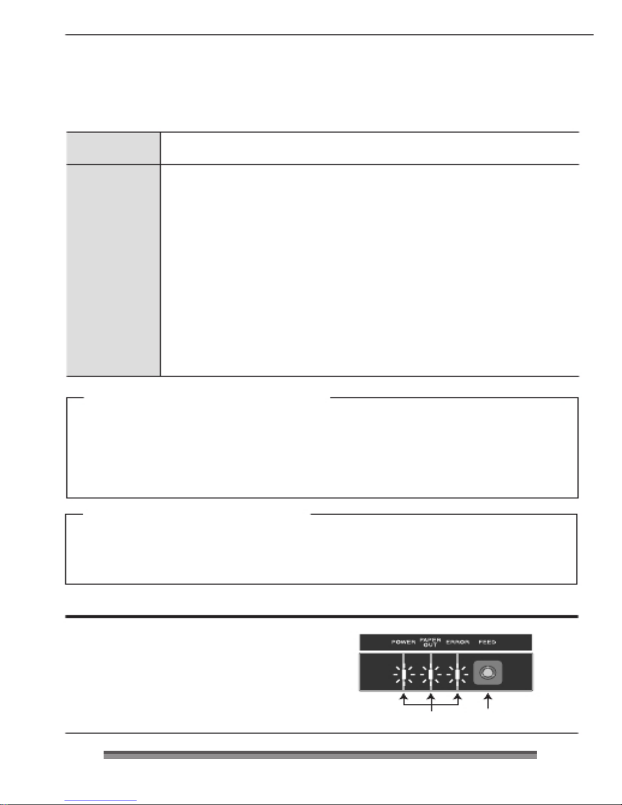
1. Pressing the FEED switch twice in
maintenance mode (POWER LED is
flashing) causes the POWER LED, PAPER
OUT LED, and the ERROR LED to begin
to flash.
Flashing
Press twice
33330000
Page 32
Chapter4
Chapter4Chapter4
Chapter4
Maintenance Mode
Initial Factory Shipping Mo
Initial Factory Shipping MoInitial Factory Shipping Mo
Initial Factory Shipping Mode
dede
de
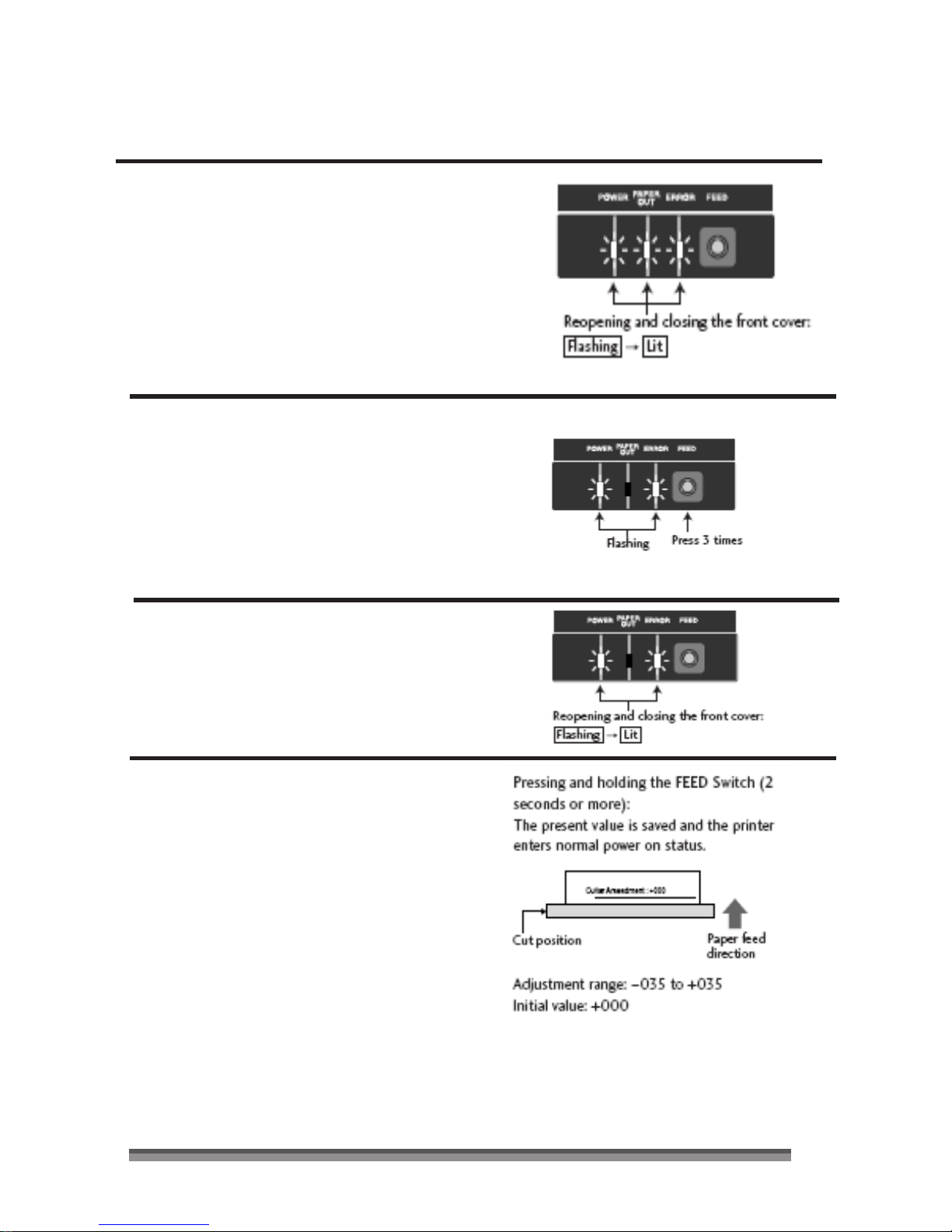
2. Reopening and closing the front cover in
this status switches the POWER LED,
PAPER OUT LED, and the ERROR LED
from flashing to continuously lit status.
3
. Pressing the FEED switch for 3 seconds or
more restores settings to the factory
shipping (initialized) status.
Cut Position Adjustment Mode
Cut Position Adjustment ModeCut Position Adjustment Mode
Cut Position Adjustment Mode
Setting the mode
Setting the modeSetting the mode
Setting the mode
1. Pressing the FEED switch 3 times in
maintenance mode (POWER LED is
flashing) causes the POWER LED and
the ERROR LED to begin to flash.
2. Reopening and closing the front cover
in this status switches the POWER LED
and the ERROR LED from flashing to
continuously lit status and enters Cut
Position Adjustment Mode.
Operating Method
Operating MethodOperating Method
Operating Method
Pressing the FEED switch (less than 2
seconds):
The present value is changed in units of
±1/144.
Opening and closing the front cover:
The ± of the adjustment direction changes.
Immediately after entering adjustment
mode, the value is changed in the +
31
3131
31
direction. Opening then closing the front
cover changes the ± of the adjusted value.
Page 33
Error Indicators
Error IndicatorsError Indicators
Error Indicators
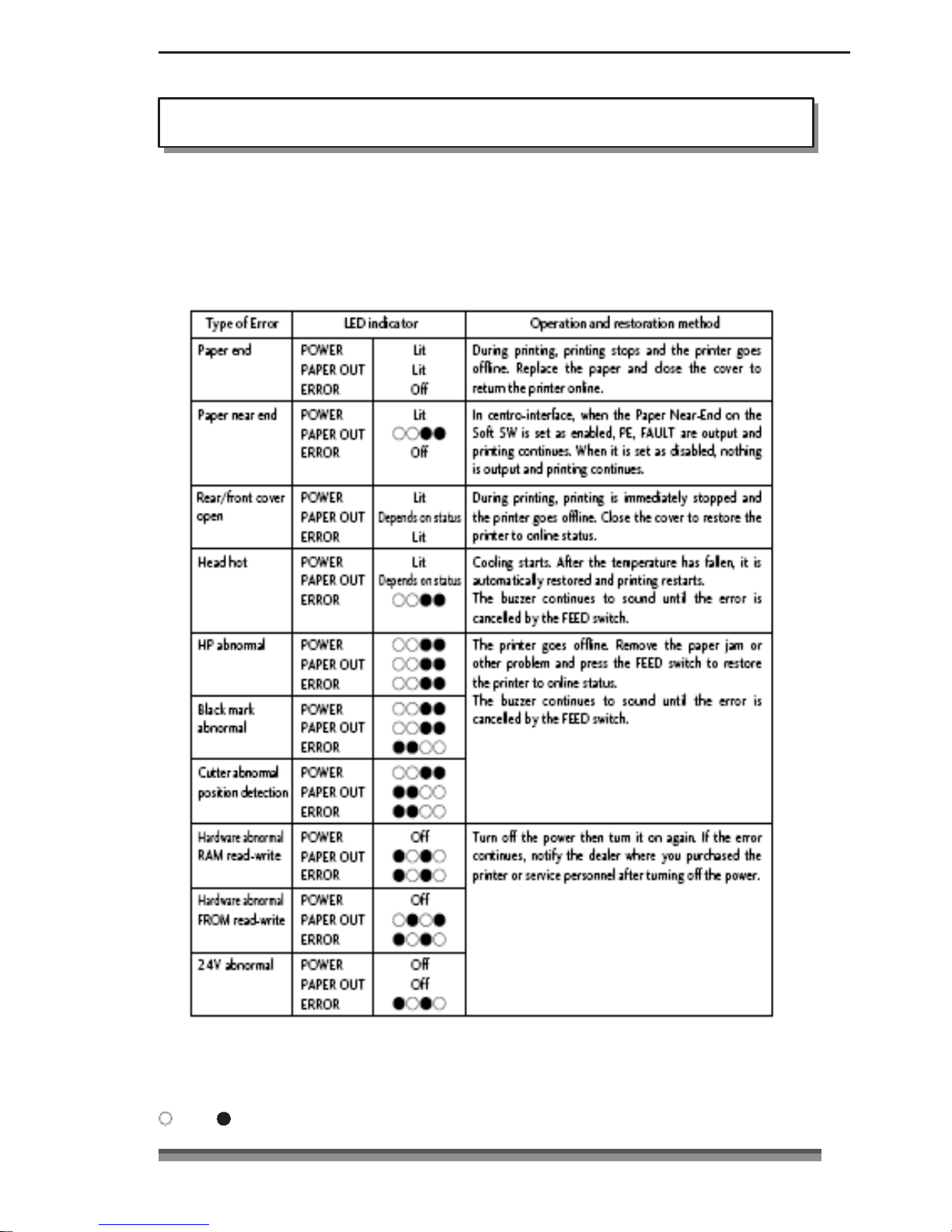
When this printer malfunctions or jams etc., the type of problem is indicated by a buzzer
and by lit or flashing LED on the operating panel.
In error status, the error indication can be cancelled by pressing the FEED switch.
Error indicator table
Error indicator tableError indicator table
Error indicator table
· There are no RS232C communication error or front cover opened/closed detection
indicators.
· If the buzzer setting is OFF in Soft SW Setting Mode, the buzzer does not sound.
: Lit, : Off
32
3232
32
Page 34
Chapter4
Chapter4Chapter4
Chapter4
Maintenance Mode
Clearing a Paper Jam
Clearing a Paper JamClearing a Paper Jam
Clearing a Paper Jam
Clearing method
Clearing methodClearing method
Clearing method
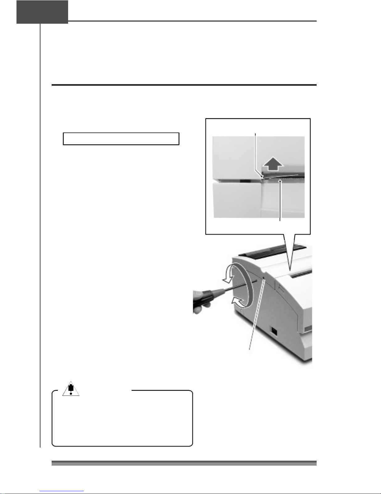
1. Turn off the power and open the rear
cover.
If the rear cover cannot be opened
When there is a cutter problem, the
printer may stop with the cutter blade
protruding so that pressing the FEED
switch fails to clear the error. When this
happens, restore the cutter blade
manually by inserting a screwdriver into
the hole on the left side surface of the
rear cover and rotating it, then open
the cover (the blade will be restored
whether you turn it to the left or right).
Turn the screw driver so that the
projections on both ends of the blade
of the cutter are returned to the back
of the printer (direction shown by the
arrow).
End of the blade of the cutter
Rear cover
Front cover
Paper cut bar
2
. Remove
all the jammed paper
(temporarily remove the roll paper
that is installed in the printer).
33
3333
33
3. Close the rear cover and turn on the
power. The auto cutter operation will
be initialized and the error cleared.
Caution
CautionCaution
Caution
When removing the jammed paper, be
careful not to touch the area around the
print head nor the cutter blade. If you
do you will be burned or cut.
Cutter lock clearing screw hole
Page 35
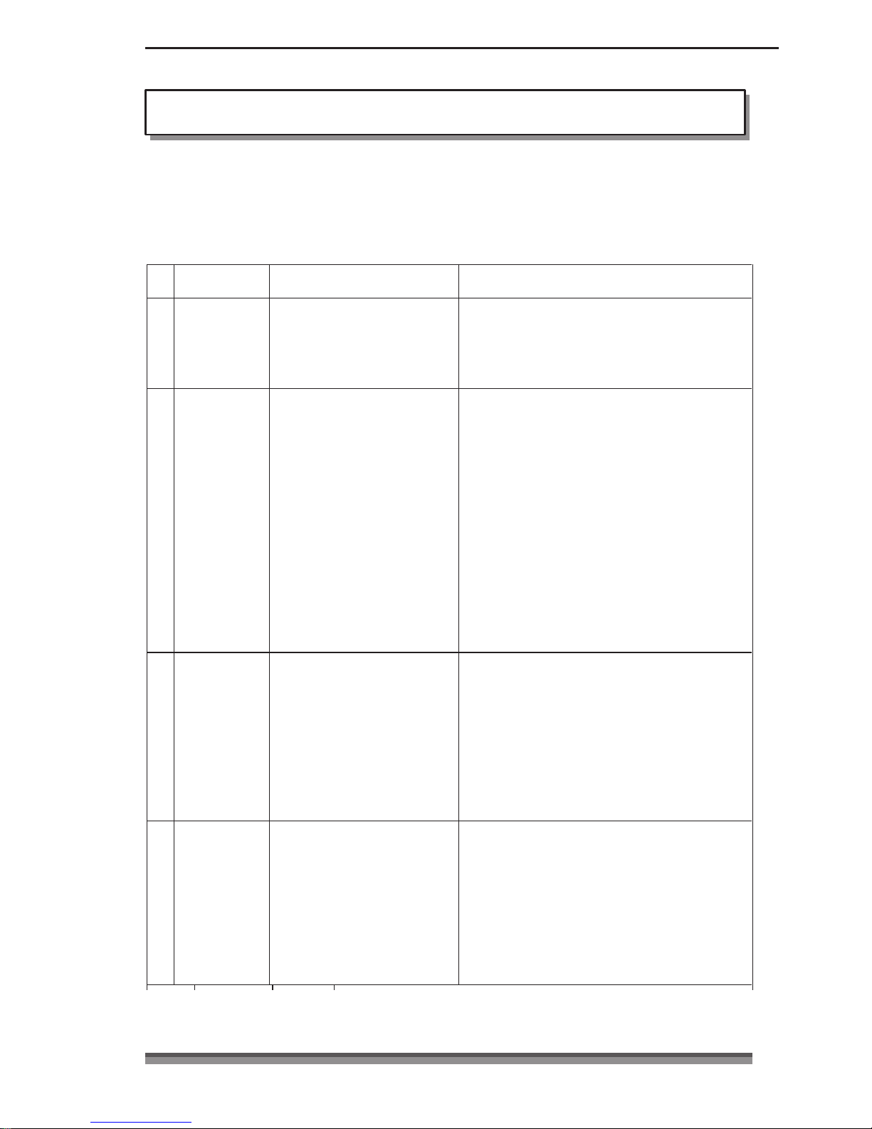
Symptom Check Action
1 Paper jam
Check for a jam at the paper
ejection opening. If you cannot
open the rear cover, do check
number 2.
Remove all the jammed paper.
Remove the roll paper from the printer and put it
back again.
2 Rear cover
does not open
Check to see if the blade of the
auto cutter is protruding.
Insert a Phillips screwdriver (+) into the cutter
lock cancel use feed hole on the printer and turn
it clockwise or counter clockwise. (Use a #1
screwdriver.)
Rotate the screwdriver while watching the paper
ejection opening and stop turning it when both
ends of the blade are fully retracted)
Caution
CautionCaution
Caution
Do not try to force the rear cover to open. If
you do, the printer will be damaged and you
will be cut by the blade.
3 Ribbon does
not feed
correctly
Turn the knob on the ribbon
cassette.
After turning the knob until the ribbon feeds
smoothly, reset the ribbon cassette.
If you cannot turn the knob, the ribbon may be
jammed inside the cassette. If the situation does
not improve, replace it with a new ribbon
cassette.
4 The paper is
not cut
Check to make sure that the
rear cover and front cover are
closed.
If one of the covers is open, close it. If the paper
still cannot be cut after you have closed the
cover, notify the dealer where you purchased the
printer or service personnel.
Trouble Shooti
Trouble ShootiTrouble Shooti
Trouble Shooting
ngng
ng
When there is trouble with this printer, take action to clear up the trouble according
to the following table.
If this action does not clear up the trouble, notify the dealer where you purchased
the printer or service personnel.
34
3434
34
Page 36

Chapter5
Chapter5Chapter5
Chapter5 Appendixes
Specifications
SpecificationsSpecifications
Specifications
Printing mode
Printing direction
Head pins
Printing line columns
Font configuration
Character types
Panel/switches
Printing speed
Paper feed
Serial impact dot matrix
Bi-directional
9 pins (: 0.3mm, Pin interval; 1/72inch)
Paper width of 76.2mm 40/42 or 33/35 columns
Paper width of 69.5mm 36/40 or 30/32 columns
Paper width of 57.5mm 30/33 or 25/27 columns
200/400 dots (full dot/including half dot)
7Ω 9 or 9Ω 9 dots
ASCII (96 characters), International characters, Katakana
Code pages:
437, KATAKANA, 850, 860, 863, 865, 852, 866, 857, 858, WPC1252
1 switch (FEED), 3 LED (POWER/PAPER OUT/ERROR), 1 buzzer
Printing: 240CPS (3P paper 200CPS)
Through-put: 76.2mm wide, 40 columns (7Ω 9+3sp, 6LPI) 5.0LPS
69.5mm wide, 36 columns (7Ω 9+3sp, 6LPI) 5.4LPS
57.5mm wide, 30 columns (7Ω 9+3sp, 6LPI) 6.0LPS
Friction feed
Minimum pitch: 1/144 inch
Paper feed speed: 40LPS (6LPI)
Paper Types: 1P roll paper
2P copy roll paper (1 original + 1 copy)
3P copy roll paper (1 original + 2 copies)
* When 3P, printing speed falls 16%
Paper widths: 76.2 / 69.5 / 57.5 (±0.5)mm
Roll diameter: 30mm to 83mm
Core diameter: Interior diameter 10
+2– 0
mm, exterior diameter 27mm or less
Paper thickness: 1P 0.06 to 0.085mm
Copy paper 0.05 to 0.20mm (total thickness)
But the total thickness that can be cut is from 0.05 to 0.14mm.
* No glue on the core or end of the paper.
Ribbon
Interface
Emulation
Method: special ribbon cassette
Colors: Single color (purple, black), 2 color (black and red)
Life: Purple, approx. 4 million characters (continuous printing at 25°C)
Black, approx. 3 million characters (continuous printing at 25°C)
Red/black, black 1.5 million characters, Red 750,000 characters
Standard model: 2 models, either RS232C or IEEE1284
ESC/POS (Page mode)
CBM mode, STAR mode
35
3535
35
Page 37
Data buffer
Features
Power
External dimensions
Receiving buffer: 40 or 4K bytes
NV bit image: 128K bytes
User NV memory: 8K
Paper-drop-in style
Auto cutter function (full cut/partial cut)
Rewinder function
Black mark sheet compatible
Copy (2P/3P) paper compatible
DKD (Drawer Kick Driver) function
ASB (Auto Status Back) function
Input: AC100V– 240V, 0.55A– 0.35A, 50/60 Hz
Power consumption: 24W
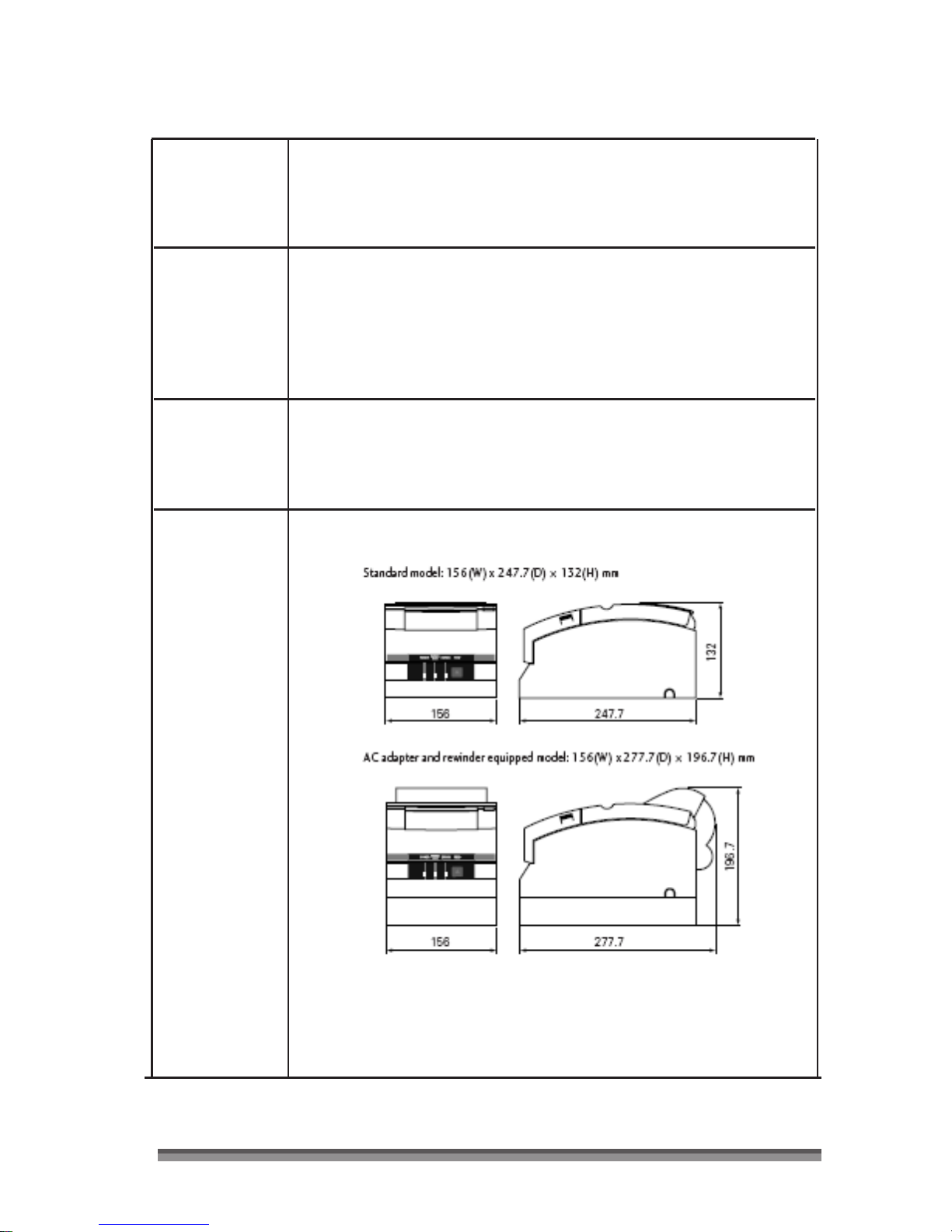
Standard model: 156(W) x 247.7(D) Ω 132(H) mm
36
3636
36
Page 38
Relative humidity
(%)
Chapter5
Chapter5Chapter5
Chapter5 Appendixes
Specifications
SpecificationsSpecifications
Specifications
Printer weight
Environmental
conditions
Standard model: 2.20kg
Auto cutter equipped model: 2.30kg
Auto cutter and rewinder equipped model: 2.45kg
But these exclude the AC adapter, AC case, ribbon, and paper.
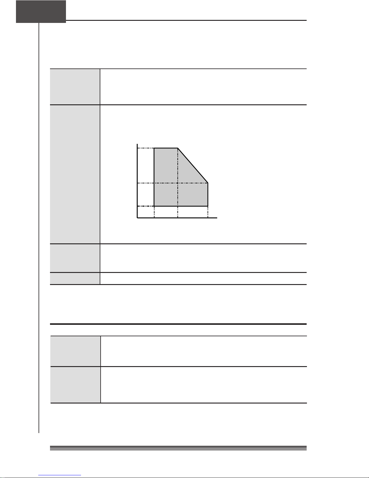
During operation: Temperature 0 to 50°C
Humidity 10 to 90%RH (no condensation)
During storage : Temperature – 20 to 70°C
Humidity 5 to 90%RH (no condensation)
90
50
10
0
35
50
Environmental temperature (°C)
Durability
Applicable standard
7.5 million lines (MCBF)
Head lifetime 150 million characters
Cutter lifetime 1 million cuts
UL, C-UL, FCC Class A, TÜV-GS, CE Marking, CCC
Ribbon
RibbonRibbon
Ribbon Cassette
CassetteCassette
Cassette
Cassette shape
Lifetime
Single color specification, color (purple) : IR-31P
color (black) : IR-31B
Two color specifi cation, colors (red/black) : IR-31RB
Single color specification, color (purple) : approx. 4 million characters
color (black) : approx. 3 million characters
Two color specifi cation, colors (red/black):
red approx. 750,000 characters/black approx. 1.5 million characters
Be sure to use a recommended ribbon cassette in order to maintain printing quality and
stabilize printer operation.
37
3737
37
Page 39

Paper
PaperPaper
Paper
Use the following printing paper in order to maintain printing quality and stabilize paper
feeding.
Roll paper
Pressure sensitive
paper
Paper width: 76.2±0.7mm (3±1/36 i nch)
69.5±0.6mm (3±1/36 i nch)
57.5±0.5mm (2.26±0.02inch)
Roll diameter:
30mm to 83mm
Core diameter: Interior diameter 10
+2– 0
mm, exterior diameter 27mm or less
Paper thickness: 0.06 to 0.085mm
Weight: 52.3 to 64.0 g/m2 (JIS P8124)
(45 to 55kg/1,000 sheets/788mm x 1,091mm)
Recommended paper: Register paper (Oji Paper Co., Ltd.) or equivalent
Non-carbon 2P/3P paper, 1 original + 1 copy /2 copies
Paper width: 76.2±0.7mm (3±1/36 i nch)
69.5±0.6mm (3±1/36 i nch)
57.5±0.5mm (2.26±0.02 inch)
Roll diameter:
30mm to 83mm
Core diameter: Interior diameter 10
+2– 0
mm, exterior diameter 27mm or less
Paper thickness: 0.05 to 0.20mm
But the total thickness that can be cut is from 0.05 to 0.14mm.
Recommended paper: 2P NCR Super (Mitsubishi Paper Mills Limited) (prints in blue)
or equivalent
Cautions concerning the roll paper
Starting to wind the roll paper (interior end) processing (with center core)
It must not be folded and its internal diameter must be even.
It must not be rolled back.
There must be no glue on its center core.
It must be wound with its printing side facing outwards.
When it is 2P paper, there must be no glue between the top and bottom sheets.
In the case of 3P paper, there must be no glue on the top, middle, or bottom papers.
Use pressure sensitive paper with total thickness no greater than 0.20mm and remember
that the printer will not cut paper with total thickness greater than 0.14mm.
If you use pressure sensitive paper with total thickness greater than 0.14mm, either do
not use the cutter or else rewind the bottom paper with the rewinder to reduce the
total thickness (top paper + middle paper) to 0.14mm or less.
38
3838
38
Page 40
Signal Name Direction Function
1
FG –
Frame ground
2 TXD Output Data transmission
3 RX D Input Data reception
4 RTS Output Same as DTR (20pin)
6 DS R Input Host reception enabled status HIGH-READY/LOW-NOT READY
[During DTR/RTS control]
The printer transmits data after it is confirmed that DSR is high.
(But transmission by DLE EOT, GS a)
[During XON/XOFF control]
Printer does not confirm DSR.
7 SG
–
Signal ground
20 DTR Output Printer READY/BUSY status HIGH-READY/LOW-BUSY
[During DTR/RTS control]
When the printer is in recepti on enabled status, it is READY, when it is
reception disabled, it is BUSY.
Printer status
1) BUSY until completion of initial settings when the power is turned on
2) BUSY in normal OFFLINE status
3) BUSY in OFFLINE status during PE
4) BUSY in OFFLINE status when other errors occur
5) BUSY when the reception buffer is full
6) BUSY during Self-Print
[During XON/XOFF control]
Always HIGH-READY except under the following conditions
1) Until completion of initial settings when the power is turned on
2) During Self-Print
25 INIT Input Printer RESET (1ms or more is higher)
PIN No.
Signal Name
1
FG
2
TXD
3
RXD
4
RTS
6
DSR
PIN No.
Signal Name
1
2
3
4
6
Chapter5
Chapter5Chapter5
Chapter5 Appendixes
Interface
InterfaceInterface
Interface
Serial (RS232C) interface
Serial (RS232C) interfaceSerial (RS232C) interface
Serial (RS232C) interface
Pin assignment
Pin assignmentPin assignment
Pin assignment
Buffer Full Control
Buffer Full ControlBuffer Full Control
Buffer Full Control
Connection with HOST
Connection with HOSTConnection with HOST
Connection with HOST
39
3939
39
Reception buffer 40/4K
8/1536 bytes
16/512 bytes
XON
XOFF
Overrun/Buffer size: 16/512 bytes
XOFF cancel size: 8/1536 bytes
Printer D-Sub25P
Host D-Sub9P
Page 41
PIN No. Signal Name Direction Function
1
FG –
Frame ground
2 TXD Output Data transmission
3 RX D Input Data reception
4 RTS Output Same as DTR (20pin)
6 DS R Input Host reception enabled status HIGH-READY/LOW-NOT READY
[During DTR/RTS control]
The printer transmits data after it is confirmed that DSR is high.
(But transmission by DLE EOT, GS a)
[During XON/XOFF control]
Printer does not confirm DSR.
7 SG
–
Signal ground
20 DTR Output Printer READY/BUSY status HIGH-READY/LOW -BUSY
[During DTR/RTS control]
When the printer is in recepti on enabled status, it is READY, when it is
reception disabled, it is BUSY.
Printer status
1) BUSY until completion of initial settings when the power is turned on
2) BUSY in normal OFFLINE status
3) BUSY in OFFLINE status during PE
4) BUSY in OFFLINE status when other errors occur
5) BUSY when the reception buffer is full
6) BUSY during Self-Print
[During XON/XOFF control]
Always HIGH-READY except under the following conditions
1) Until completion of initial settings when the power is turned on
2) During Self
-
Print
Parallel (IEEE1284) Interface
Parallel (IEEE1284) InterfaceParallel (IEEE1284) Interface
Parallel (IEEE1284) Interface
Pin assignment
Pin assignmentPin assignment
Pin assignment
(*: Active Low)
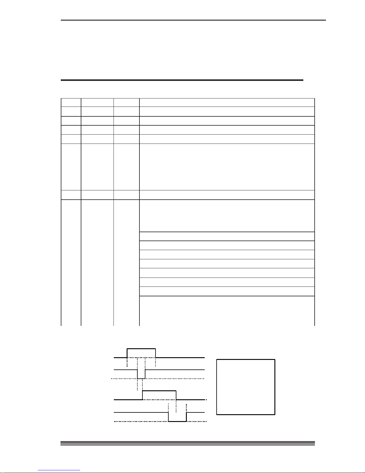
Data Reception Timing
Data Reception TimingData Reception Timing
Data Reception Timing
Data 1– 8
STROBE
BUSY
A
B
D
C
E
F
A : MIN. 1∝s
B : MIN. 1∝s
C : MIN. 1∝s
D : MAX. 1∝s
E : Approx. 3.2∝s
F : Approx. 3.2∝s
ACK
44440000
Page 42
PIN No. Signal Name Direction Function
1
FG –
Frame ground
2 TXD Output Data transmission
3 RX D Input Data reception
4 RTS Output Same as DTR (20pin)
6 DS R Input Host reception enabled status HIGH-READY/LOW
-
[During DTR/RTS control]
Chapter5
Chapter5Chapter5
Chapter5 Appendixes
Parallel (IEEE1284) Interface
Parallel (IEEE1284) InterfaceParallel (IEEE1284) Interface
Parallel (IEEE1284) Interface
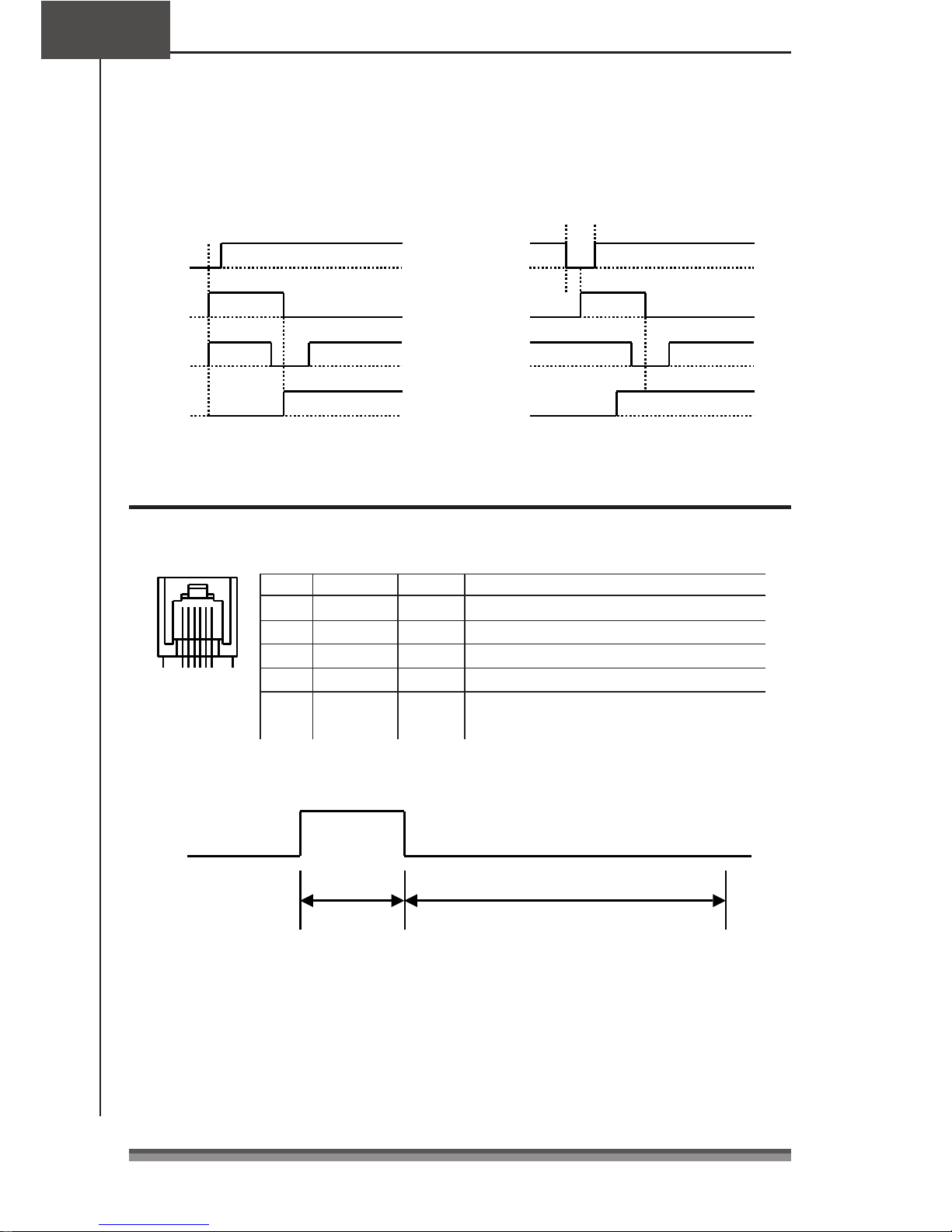
Timing when power is on
Timing when power is onTiming when power is on
Timing when power is on
INIT
INITINIT
INIT signal timing
signal timingsignal timing
signal timing
A
A : More than 16∝s
RESET
INT
BUSY
ACK
SEL ECT
BUSY
ACK
FAULT
B
B : Less than 200∝s
Drawer Kick
Drawer KickDrawer Kick
Drawer Kick----Out Interface
Out InterfaceOut Interface
Out Interface
Pin assignment
Pin assignmentPin assignment
Pin assignment
6
1
The ESC pm t1 t2 commands select either Drawer Kick-out Signal 1 or 2 to set the
pulse time.
T1 x 2ms
When ON
T2 x 2ms
When OFF
Note:
Note:Note:
Note:
· T2 (when OFF) ε T1 (when ON) &4 is satisfied.
· The maximum amperage at +24V is up to 1A. When connected to one that exceeds
1A, the printer and connected equipment may be damaged.
41
4141
41
 Loading...