

Page 1
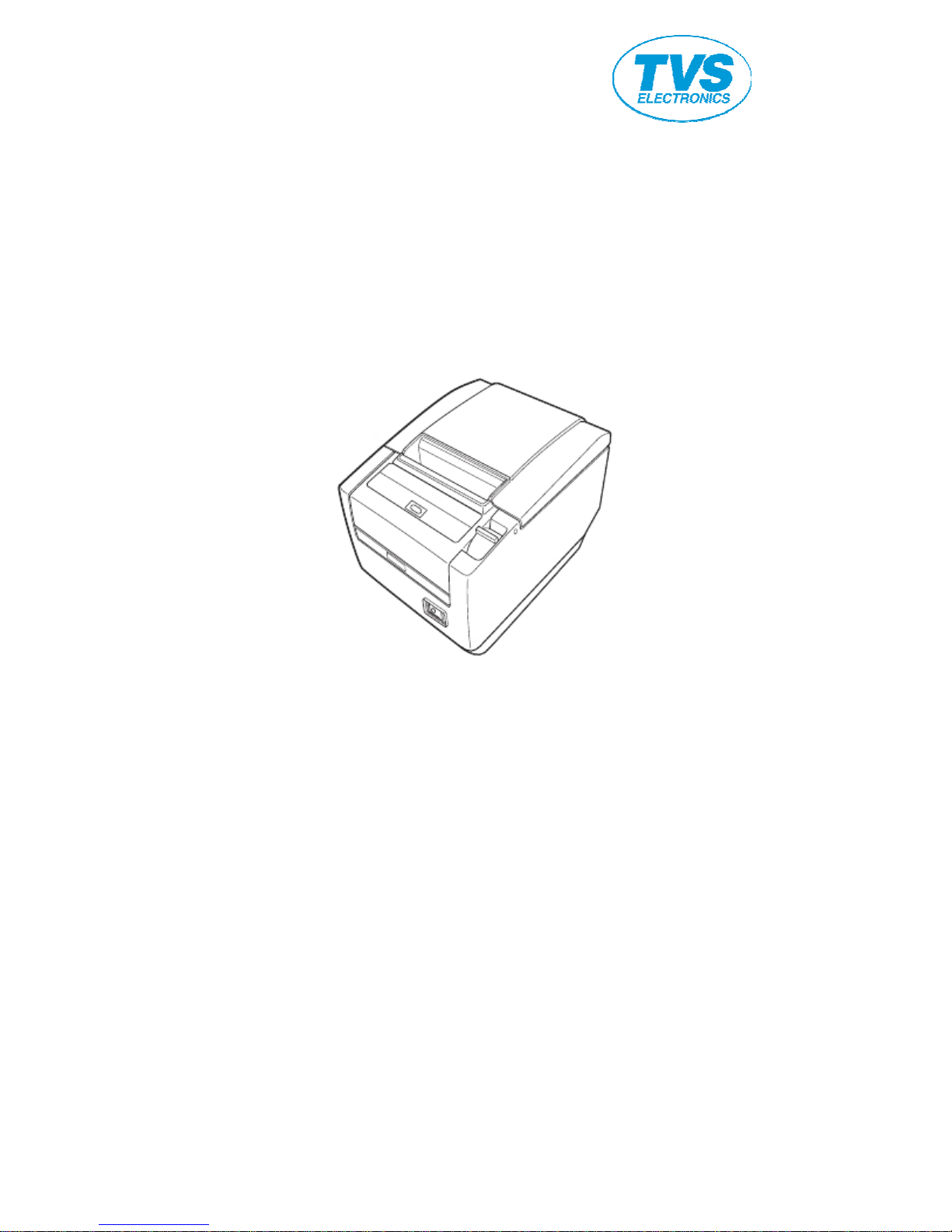
LINE THERMAL PRINTER
MODEL RP-3200
User’ s Manual
Page 2
SAFETY PRECAUTIONS
...WHICH SHOULD BE STRICTLY OBSERVED
Before using this product for the first time, carefully read these SAFETY PRECAUTIONS.
Improper handling may result in accidents (fire, electric shock or injury).
In order to prevent injury to operators, third parties, or damage to property, special
warning symbols are used in the User’ s Manual to indicate important items to be strictly
observed.
After having read this Manual, keep it in a safe, readily accessible place for future
reference.
Some of the descriptions contained in this manual may not be relevant to some printer
models.
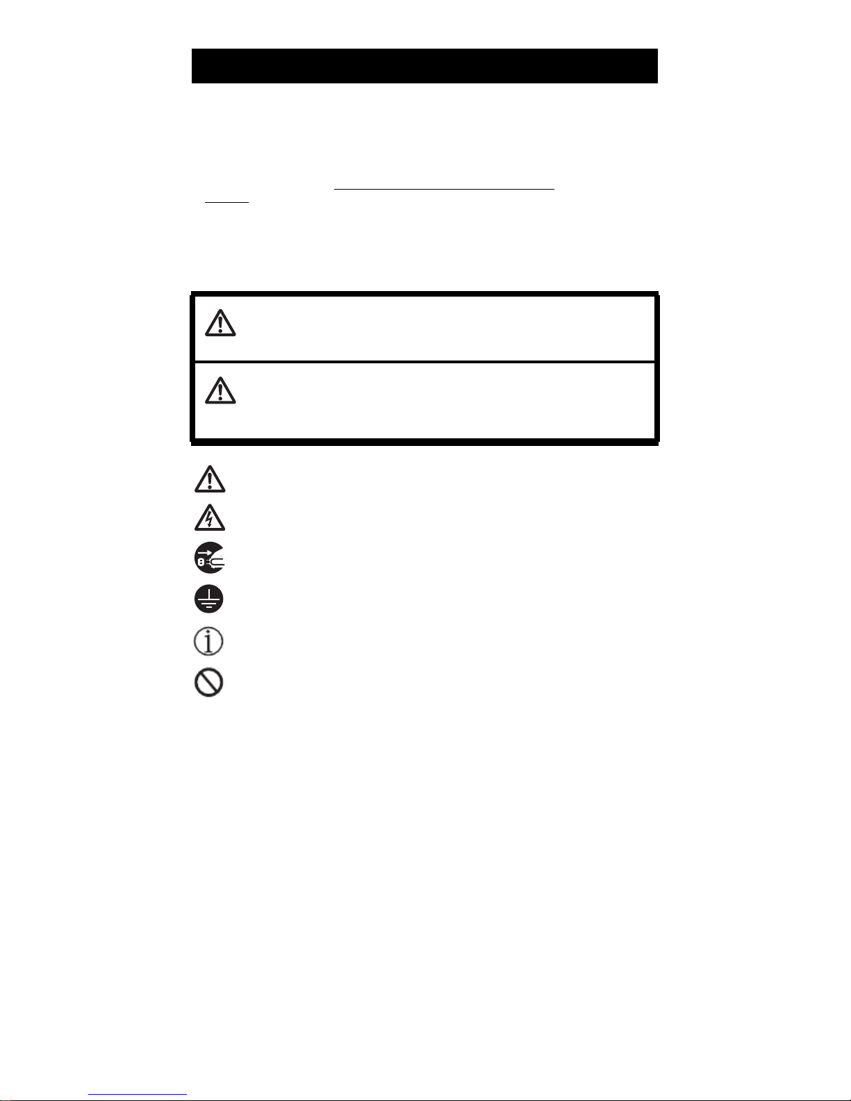
The following describes the degree of hazard and damage that could occur if the printer
is improperly operated by ignoring the instructions indicated by the warning symbols.
WARNING
Neglecting precautions indicated by this symbol may result in fatal or serious injury.
CAUTION
Neglecting precautions indicated by this symbol may result in injury or damage to
property.
This symbol is used to alert your attention to important items.
This symbol is used to alert you to the danger of electric shock or electrostatic
damage.
This symbol denotes a request to unplug the printer from the wall outlet.
This symbol is used to indicate that the power supply must be grounded.
This symbol is used to indicate useful information, such as procedures,
instructions or the like.
This symbol is used to indicate prohibited actions.
—2—
Page 3
PRECAUTIONS ON PRINTER INSTALLATION
WARNING
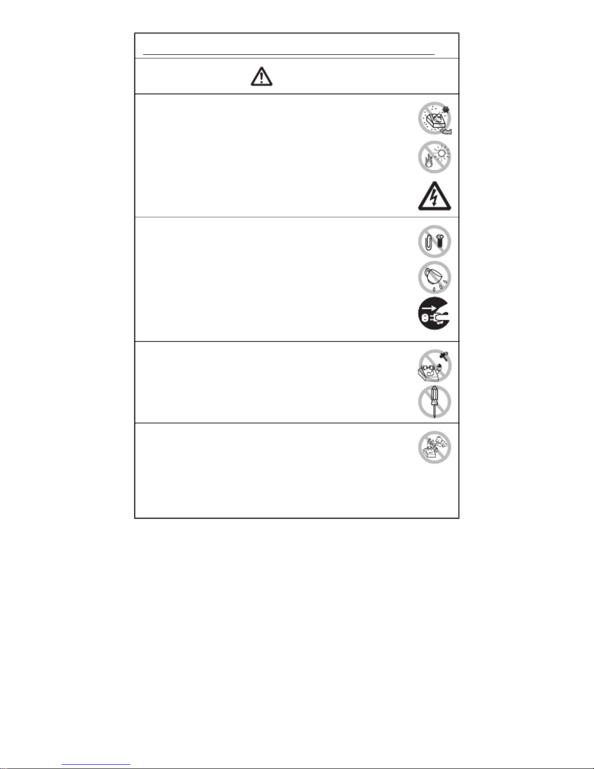
Do not use or store this product in a place where it will be exposed to:
* Flames or moist air.
* Direct sunlight.
* Hot airflow or radiation from a heating device.
* Salty air or corrosive gases.
* Ill-ventilated atmosphere.
* Chemical reactions in a laboratory.
* Airborne oil, steel particles, or dust.
* Static electricity or strong magnetic fields.
· Neglecting these warnings may result in printer failure, overheating,
emission of smoke, fire, or electric shock.
Do not drop any foreign object nor spill liquid into the printer. Do not
place any object on the printer either.
Do not drop any metallic object such as paper clips, pins or screws
into the printer.
Do not place a flower vase, pot, or anything containing water on the
printer.
Do not spill coffee, soft drinks, or any other liquid into the printer.
Do not spray insecticide or any other chemical liquid over the printer.
· Dropping a metallic foreign object into the printer, may cause printer
failure, fire, or electric shock. Should it occur, immediately turn the
printer off, unplug it from the supply outlet, and call your local dealer.
Do not handle the printer in the following ways:
Do not subject the printer to strong impacts or hard jolts (e.g., being
stepped on, dropped or struck).
Never attempt to disassemble or modify the printer.
· Neglecting to handle properly may result in printer failure,
overheating, emission of smoke, fire, or electric shock.
Install, use, or store the printer out of the reach of children.
· Electric appliances could cause an unexpected injury or accident if
they are handled or used improperly.
· Keep the power cord and signal cables out of the reach of children.
Also children should not be allowed to gain access to any internal
part of the printer.
· The plastic bag the printer came in must be disposed of properly or
kept away from children. Wearing it over the head may lead to
suffocation.
—3—
Page 4
CAUTION
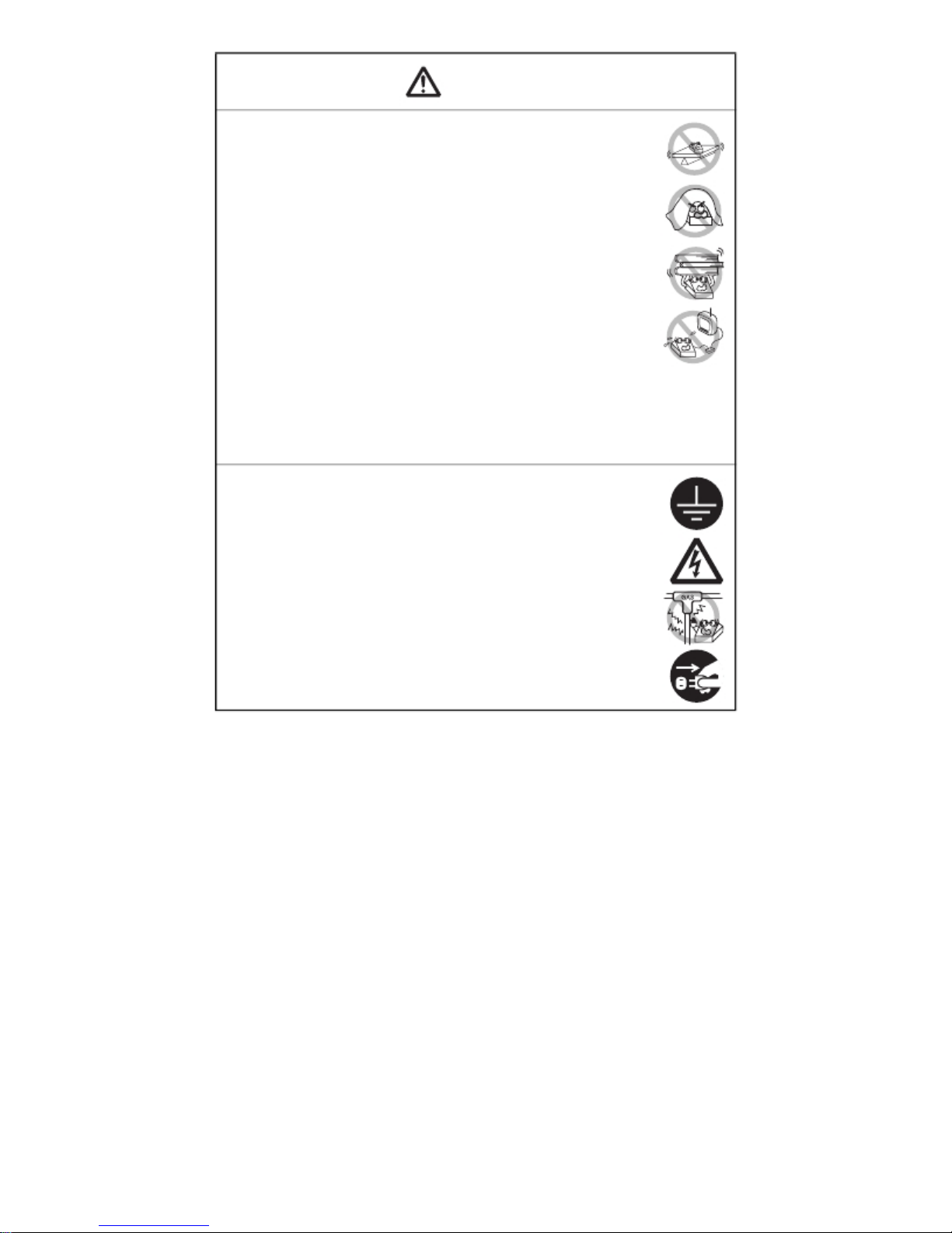
Do not use the printer under the following conditions.
Avoid locations subject to vibration or instability.
Avoid locations where the printer is not level.
· The printer may fall and cause an injury.
· The quality of printing may deteriorate.
Do not obstruct the printer’ s air vents.
Do not place anything on the printer.
Do not cover or wrap the printer in cloth or blankets.
· Doing so could cause heat to build up and deform the case or start a
fire.
Avoid using the printer near a radio or TV set or from supplying it from
the same electric outlet as these appliances.
Avoid using the printer interconnected with a cable or cord that has
no protection against noise. (For interconnections, use shielded or a
twisted pair of cables and ferrite cores, or other anti-noise devices.)
Avoid using the printer with a device that is a strong source of noise.
· The printer may have an adverse effect on nearby radio or TV
transmissions. There may also be cases when nearby electrical
appliances adversely influence the printer, causing data errors or
malfunction.
Installed in any orientation other than those specified.
· Malfunction, failure, or electric shock may result.
Connect the printer to a ground.
· Electric leakage may cause an electric shock.
Do not connect the printer’ s ground to any of the following:
* Gas piping
· A gas explosion could result.
* Telephone line ground
* Lightning rod
· If lightning strikes a large surge of current may cause fire or
shock.
* Water pipes
· Plastic water pipes should not be used for grounding. (Those
approved by a Waterworks Department may be used.)
Before connecting or disconnecting the grounding lead to or from the
printer, always unplug it from the electric outlet.
—4—
Page 5
PRECAUTIONS IN HANDLING THE PRINTER
WARNING
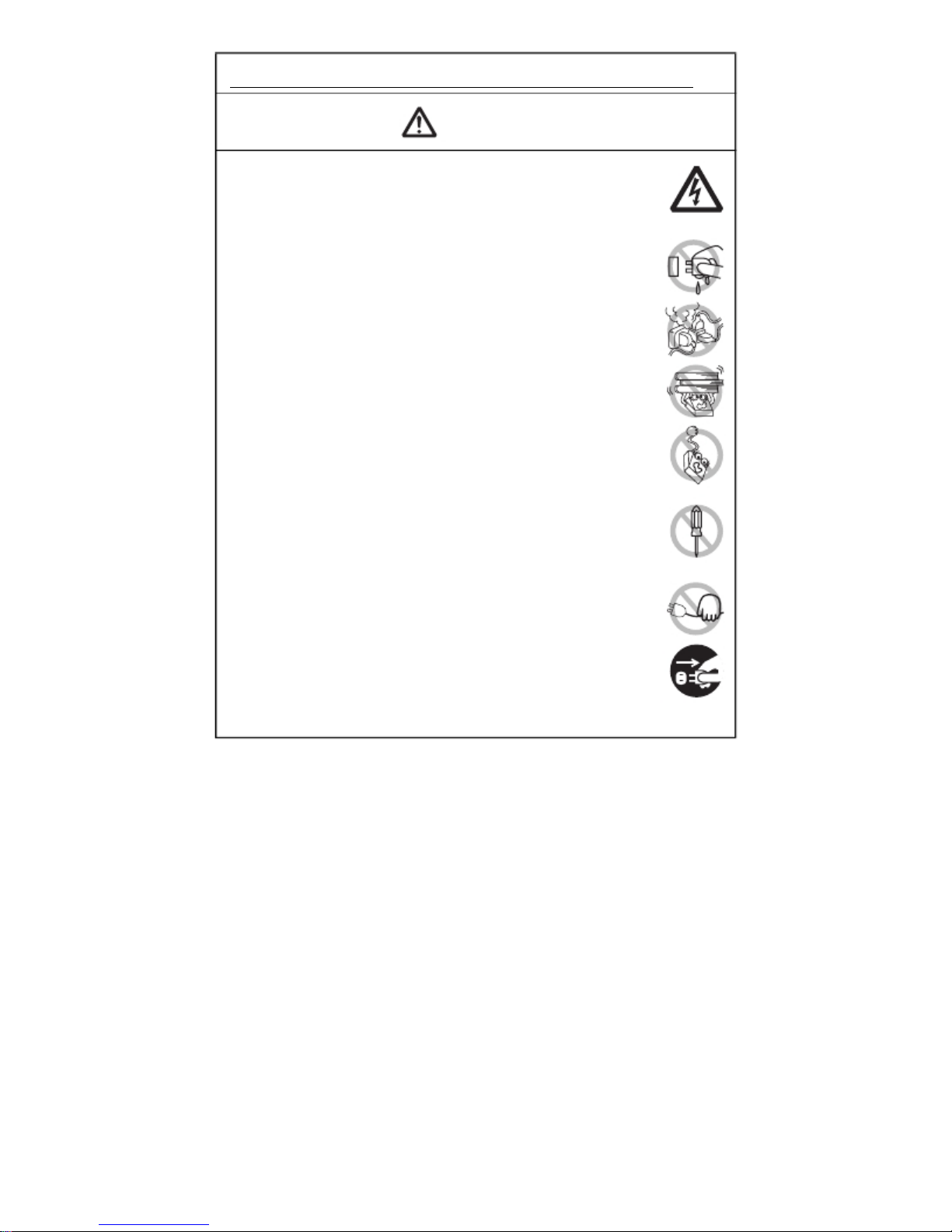
Please observe the following precautions for power source and power
cord:
Do not plug or unplug the power cord with a wet hand.
Use the printer only at the specified supply voltage and frequency.
Use only the specified AC adapter with the printer.
Check to make sure that the supply outlet from which the printer is
powered has a sufficient capacity.
Do not supply the printer from a power strip or current tap shared with
other appliances.
Do not plug the power cord into an electric outlet with dust or debris
left on the plug.
Do not use a deformed or damaged power cord.
Do not move the printer while its power is on.
· Neglecting to handle it properly may result in printer failure, emission
of smoke, fire, or electric shock.
· An overload may cause the power cord to overheat, catch fire, or the
circuit breaker to trip.
Do not allow anything to rest on the power cord. Do not place the
printer where the power cord may be stepped on.
Do not use or carry the printer with its power cord bent, twisted, or
pulled.
Do not attempt to modify the power cord unnecessarily.
Do not place the power cord near any heating device.
· Neglecting these cautions may cause wires or insulation to break,
which could result in electric leakage, electric shock, or printer failure.
If the power cord sustains damage, contact your dealer.
Do not leave things around the electric outlet.
Supply power to the printer from a convenient electric outlet, readily
accessible in an emergency.
· Pull the plug to immediately shut it down in an emergency.
Insert the power plug fully into the outlet.
If the printer will not be used for a long time, disconnect it from its
electric outlet.
Hold the plug and connector when plugging or unplugging the power
cord or signal cable after turning off the printer and the appliance
connected to it.
—5—
Page 6
CAUTION
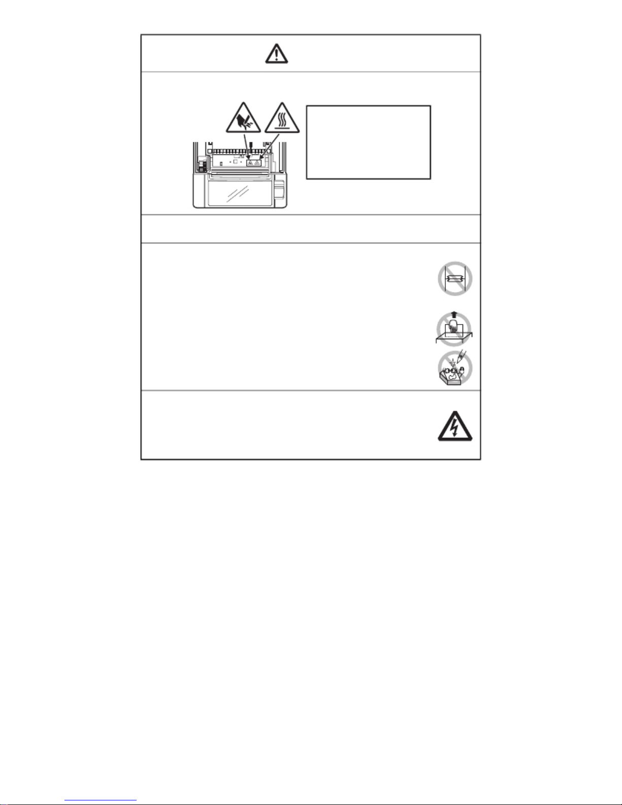
Caution label is attached in the position shown in the following figure. Carefully read
the handling precautions before using the printer.
THIS LABEL INDICATES THE
RISK OF BURNS DUE TO THE
HIGH TEMPERATURE OF THE
PRINT HEAD AND A RISK OF
BEING CUT BY THE MANUAL
AND AUTO CUTTERS WHILE
THE PAPER COVER IS OPEN.
Do not transport this printer with the paper roll inside.
· Printer failure or damage may occur.
To prevent possible malfunction or failure observe the following.
Avoid operating the printer without paper properly loaded.
Avoid the use of paper not complying with specifications.
· May result in poor print quality.
Avoid using torn pieces of paper or paper spliced with plastic adhesive
tape.
Avoid forcibly pulling already loaded paper by hand.
Avoid using a sharp pointed device to operate panel buttons.
Be sure to firmly insert the cable plugs into their mating sockets.
· A cross connection may damage the printer’ s internal electronics or
the host system’ s hardware.
Only use the printer with devices that have designated solenoid
specifications for the cash drawer interface connector.
· Neglecting this caution may result in malfunction or failure.
—6—
Page 7
CAUTION
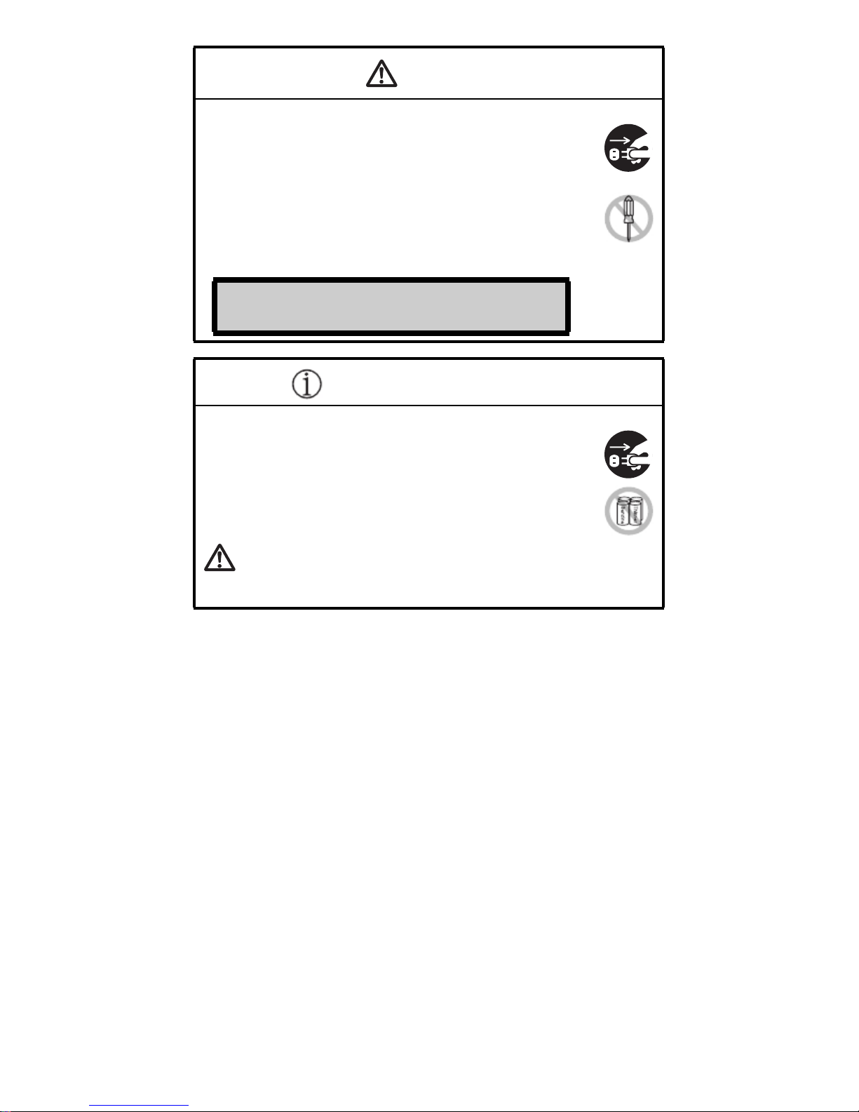
To prevent injury and printer failures from worsening, observe the following:
While the paper cover is open, be careful to not touch the manual
cutter that is in the paper eject slot.
Do not touch the printing surface of the thermal head.
Do not touch any of the moving parts (e.g., paper cutter, gears, active
electric parts) while the printer is working.
In case of trouble do not attempt to repair the printer. Ask TVSE
service for repair.
Be careful that the covers do not pinch your hands or fingers.
Be careful of the sharp edges on the printer. Do not allow them to
injure you or damage property.
· May result in electric shock, burn, or injury.
If the printer emits smoke, an odd smell, or unusual noise while
printing, immediately abort the current print session and
unplug the printer from the electric outlet.
DAILY MAINTENANCE
Observe the following precautions for daily maintenance.
When cleaning the printer, always turn it off and unplug it from the
electric outlet.
Use a soft, dry cloth for cleaning the surface of the printer case.
For severe stains, use a soft cloth slightly dampened with water.
Never use organic cleaning solvent such as alcohol, paint thinner,
trichloroethylene, benzene, or ketone. Never use a chemically
processed cleaning cloth.
To remove paper dust, use a soft brush.
CAUTION
· The thermal head is at a dangerously high temperature immediately after printing.
Allow it to cool off before starting maintenance work.
—7—
Page 8

THE TABLE OF CONTENTS
1. GENERAL OUTLINE .................................................................... 9
1.1
Features .......................................................................................... 9
1.2
Basic Specifications..................................................................... 10
2. EXPLANATION OF PRINTER PARTS ....................................... 11
2.1 Printer Appearance...................................................................... 11
2.2 Inside the paper cover................................................................. 14
2.3 Other Built-in Functions .............................................................. 15
3. SETUP........................................................................................ 16
3.1 Connecting the AC Power Cord.................................................. 16
3.2 Connecting Interface Cables ....................................................... 17
3.3 Connecting the Cash Drawer ...................................................... 18
3.4 Precautions for Installing the Printer ......................................... 20
3.5 Partition for Paper Roll ................................................................ 21
3.6 Setting the DIP Switch on the Serial Interface Board ............... 22
3.7 Adjusting the Paper Near-end Sensor ....................................... 23
3.8 Setting Paper Thickness.............................................................. 24
3.9 Loading Paper .............................................................................. 25
3.10 Attaching the Power Switch Cover........................................... 26
3.11 Attaching the Interface Cover ................................................... 27
3.12 Removing the Interface Cover .................................................. 27
4. MAINTENANCE AND TROUBLESHOOTING........................... 28
4.1
Periodic Cleaning......................................................................... 28
4.2
Clearing a Cutter Lock (1)............................................................ 29
4.3
Clearing a Cutter Lock (2)............................................................ 30
4.4
Self-printing ................................................................................. 31
4.5
Hexadecimal Dump Printing....................................................... 32
4.6
Error Messages ............................................................................ 33
5. OTHER ....................................................................................... 35
5.1 External Views and Dimensions................................................. 35
5.2 Printing Paper .............................................................................. 36
5.3 Manual Setting of Memory Switches ........................................ 37
—8—
Page 9

1. GENERAL OUTLINE
The RP-3200 line thermal printer series is designed for use with a broad array
of terminal equipment including data, POS, and kitchen terminals.
These printers have extensive features so they can be used in a wide range of
applications.
1.1 Features
High-speed (200 mm/s) printing.
Design so compact it can be installed anywhere (maximum 3-inch (83-mm)
paper roll size)
Choose from two models with either 3-inch (83/80 mm) or 2-inch (60/58 mm)
wide paper rolls.
Built-in power supply or AC adapter types available
Printer status and errors indicated by LED and a buzzer
Equipped with a fast and quiet cutter
Easy to clear cutter jams
Interchangeable interface
Built-in cash drawer kick-out interface
Memory switches make customization possible
Store user-defined characters and logos on user memory
Barcode and 2D barcode printing supported
2-color printing supported (when specified paper used)
Driver and utility software included
—9—
Page 10
1.2 Basic Specifications
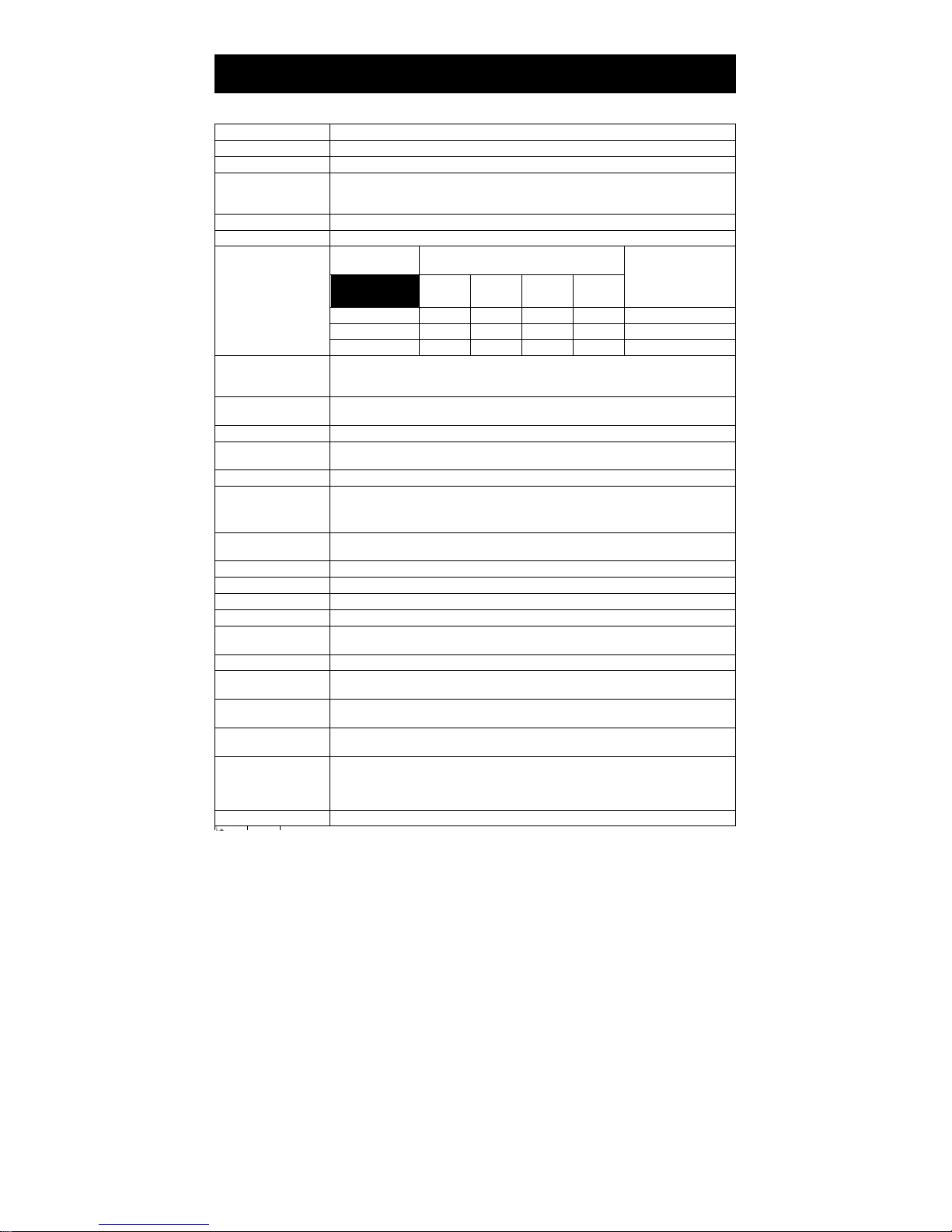
Item Specifications
Model RP-3200
Print method Line thermal dot print method
Print width *1 80 mm/640 dots, 72 mm/576 dots, 64 mm/512 dots, 54.5 mm/436 dots,
Dot density
Print speed 200 mm/s (fastest, print density 100%), 1600 dot-lines/s
Number of print
columns *2
Character size*3
Character type Alphanumeric, international, PC437/850/852/857/858/860/863/864/865/866/
User memory 384 KB (capable of storing user-defined characters and logos)
Bar code types UPC-A/E, JAN (EAN) 13/8 columns, ITF, CODE39, CODE128, CODABAR (NW-7),
Line spacing 4.25 mm (1/6 inch) (changeable using commands)
Paper roll
Interface parallel (IEEE 1284 compliant), USB
Cash drawer kick-out Supports 2 cash drawers
Buffer size 4 k bytes/45 bytes
Supply voltage
Power consumption Approximately 45 W (normal printing), 3 W (standby)
AC adapter *4
(36AD3)
Weight Approx. 2 kg
Outside dimensions
Operating temperature
and humidity
Storage temperature
and humidity
Reliability Print head life: 150 km, 200 million pulses (at normal temperature and
Safety standard *5 UL, C-UL, FCC Class A, TÜV-Bauart, CE Marking
54 mm/432 dots, 52.5 mm/420 dots, 48 mm/384 dots, 45 mm/360 dots,
48.75 mm/390 dots, 68.25 mm/546 dots
8 ⋅ 8 dots/mm (203 dpi)
—
Paper width
Font
Font A 53 48 36 35
Font B 71 64 48 46
Font C 80 72 54 52
Font A: 1.50 ⋅ 3.00 mm
Font B: 1.13 ⋅ 2.13 mm
Font C: 1.00 ⋅ 2.00 mm
WPC1252/katakana/Thai code 18
CODE93, PDF417, QR Code
Paper roll: 83 -1 mm/80 -1 mm/60 -1 mm/58 -1 mm ⋅ maximum ⎞83 mm
Paper thickness: 65-75 ⎧m (core tube diameter: inner 12 mm/outer 18 mm)
DC 24 V ±5%
Rated input: AC 100 to 240 V, 50/60 Hz, 150 VA
Rated output: DC 24 V, 2.1 A
145 (W) ⋅ 192 (D) ⋅ 148 (H) mm
5 to 45°C, 10 to 90% RH (no condensation)
-20 to 60°C, 10 to 90% RH (no condensation)
humidity using recommended paper)
Auto cutter life: 2 million cuts (at normal temperature/humidity, using
recommended paper and paper thickness)
Maximum number of characters
(columns)
83 mm 80 mm 60 mm 58 mm
+0 +0 +0 +0
75-85 ⎧m (core tube diameter: inner 25.4 mm/outer 32 mm)
— 10 —
Dot configuration
(dots)
12 ⋅ 24
9 ⋅ 17
8 ⋅ 16
Page 11
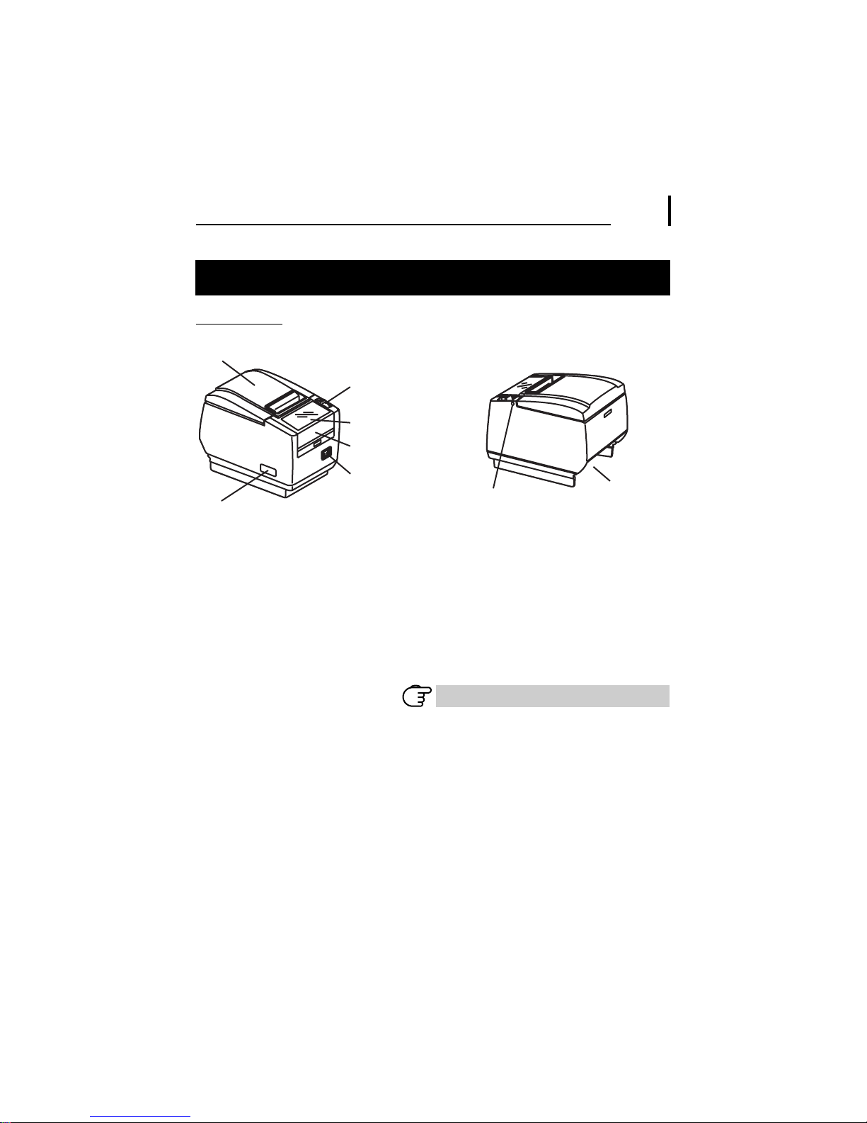
2. EXPLANATION OF PRINTER PARTS
2.1 Printer Appearance
Names of parts
Paper cover
Cover open lever
Operation panel
Front cover
Power switch
Maintenance cover
(Front view)
Paper cover
Open to load paper.
Cover open lever
Use this lever to open the paper cover.
Front cover
Open and close this cover to clear a cutter lock.
Refer to 4.3 Clearing a Cutter Lock (2)
Front cover release button
Press this button to open the front cover.
— 11 —
Front cover
release button
(Rear view)
Rear connectors
Page 12
Power switch
Press this button to turn the power on or off.
Maintenance cover
Not applicable for this product.
CAUTION
Do not open the maintenance cover.
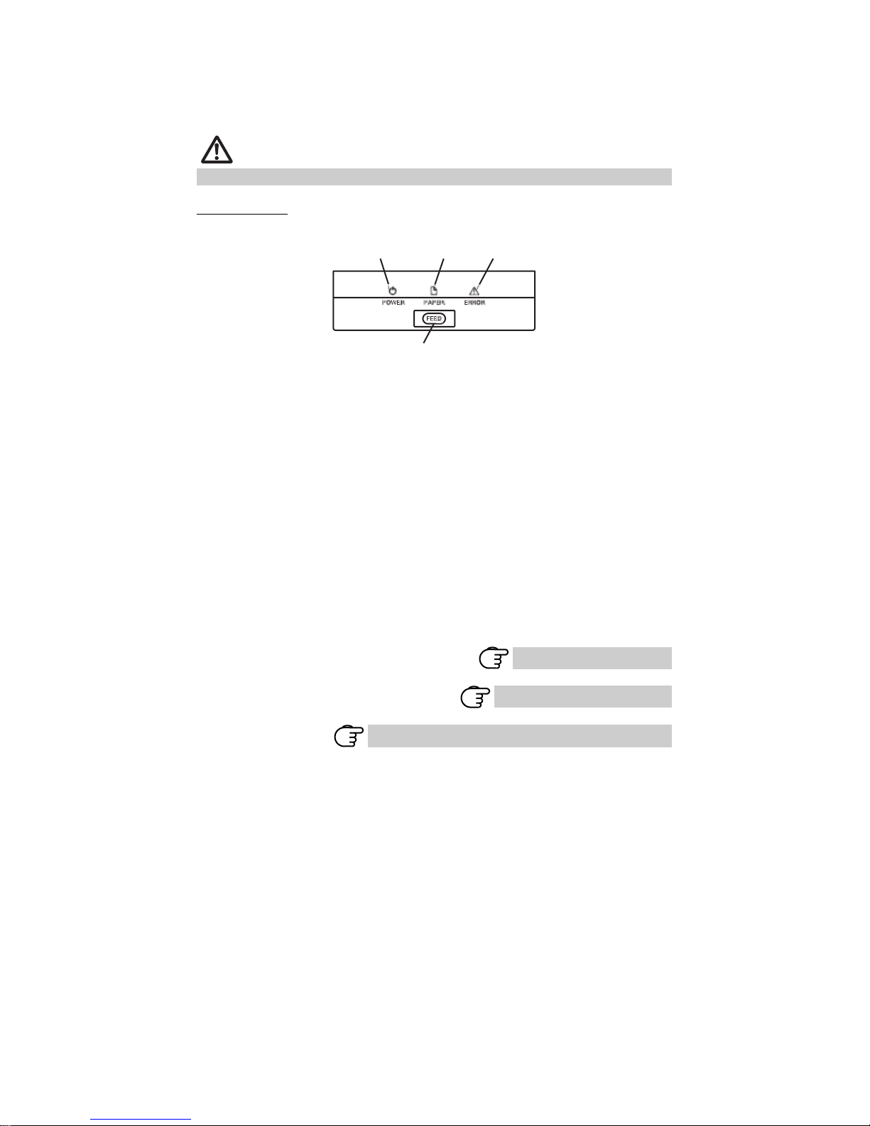
Operation panel
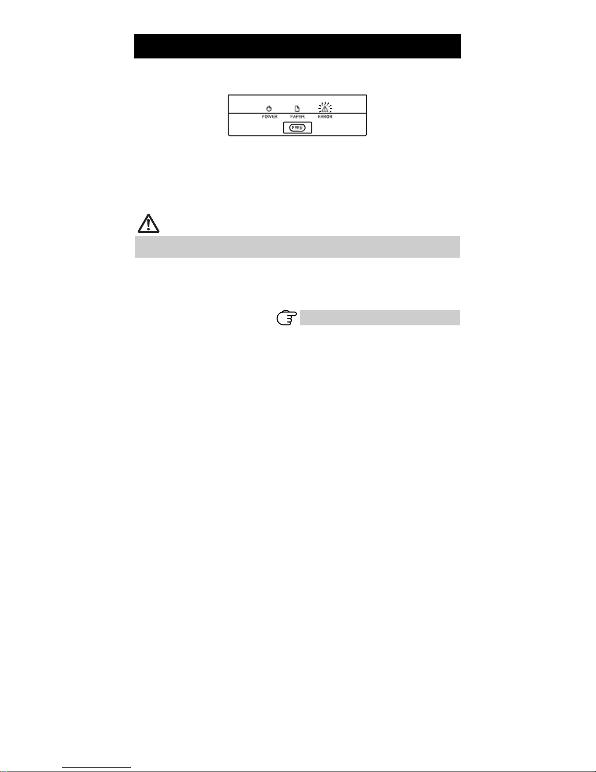
POWER LED (green)
POWER LED (green)
Lights when the power is on, turns off when the power is off.
Flashes when data is incoming or a memory error has occurred.
PAPER LED (orange)
Lights orange when paper is low (paper near-end) or there is no paper (paper
end).
ERROR LED (red)
Flashes if the print head is hot, the paper cover is open, a cutter lock occurs,
and so forth.
FEED button
Press this button to feed paper.
In case of a cutter lock, remove the cause of the lock, close the paper cover,
and then press the FEED button.
The printer enters the mode for setting memory switches and running selfprinting.
Refer to 5.3 Manual Setting of Memory Switches
PAPER LED
(orange)
FEED button
— 12 —
ERROR LED (red)
Refer to 4.4 Self-printing
Refer to 4.6 Error Messages
Page 13

Rear connectors
Interface connector
(serial, parallel, USB, etc.)
Cash drawer
kick-out
connector
Power connector (AC adapter type)
AC inlet (built-in power supply type)
Interface connector (serial, parallel, USB, etc.)
Connects to the interface cable.
The serial interface board is equipped with a DIP switch.
Cash drawer kick-out connector
Connects to the cable from the cash drawer.
Power connector (AC adapter type)
Connects to the AC adapter cable.
AC inlet (built-in power supply type)
Connects to the AC power cord.
— 13 —
Page 14
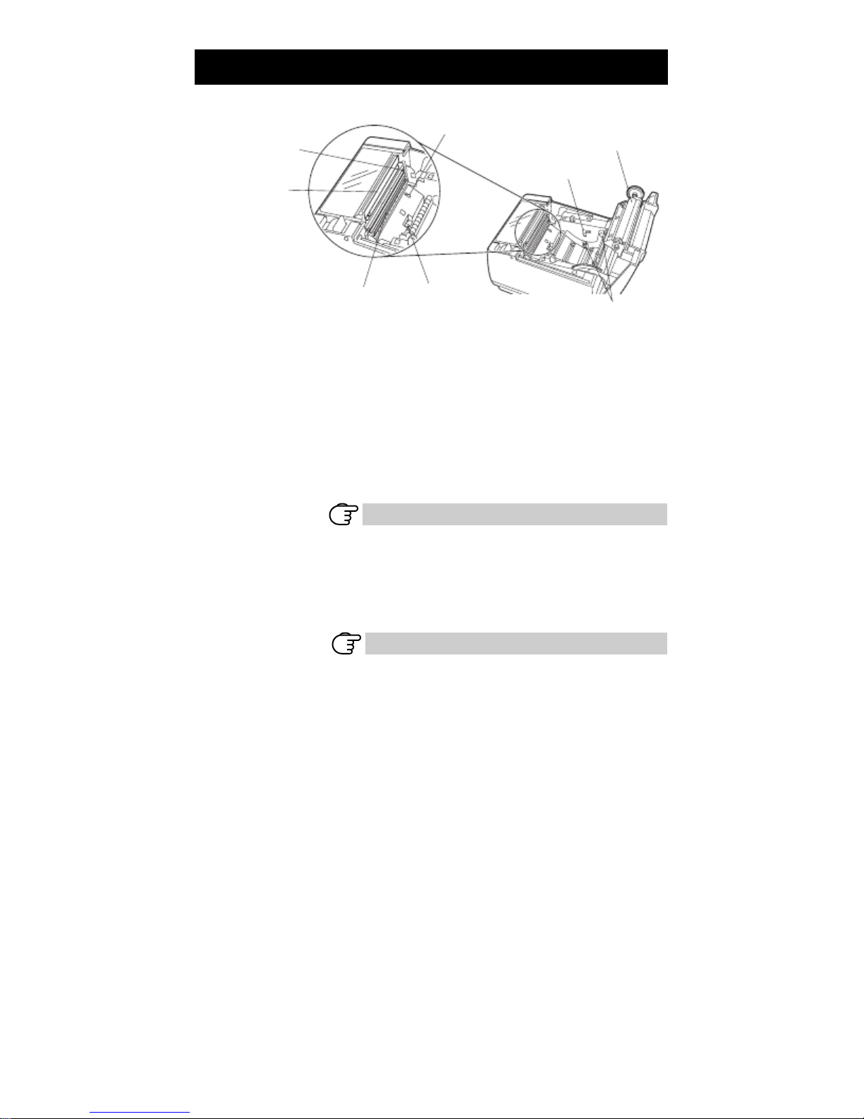
2.2 Inside the paper cover
Auto cutter
Manual cutter
Print head (thermal) Paper thickness
Platen
Feeds the paper.
Paper near-end sensor (PNE sensor)
Detects when the paper is near the end of the roll. Adjust the position of the
sensor to determine when it detects the end of the paper is near.
Button to change paper near-end sensor
Change the position of the paper near-end sensor to match the paper being
used.
Refer to 3.7 Adjusting the Paper Near-end Sensor
Manual cutter
For cutting the paper manually when printing is finished.
Auto cutter
Automatically cuts the paper when printing is finished.
Refer to 5.3 Manual Setting of Memory Switches
Print head (thermal)
Prints characters and graphic data on paper (paper rolls).
Paper end sensor (PE sensor)
Detects when there is no paper. Printing stops when this sensor detects there
is no paper.
Paper-end sensor
(PE sensor)
selection lever
— 14 —
Button to change paper
near-end sensor
Paper near-end sensor
(PNE sensor)
Platen
Page 15

Paper thickness selection lever
Use this lever to select regular or thick paper according to the thickness of the
paper being loaded.
CAUTION
Do not change the position of the paper thickness selection lever from the factory
setting.
Refer to 3.8 Setting Paper Thickness
2.3 Other Built-in Functions
Buzzer
Buzzes when errors occur or when operations or command operations are
performed.
User memory
You can save user-defined logo and character data in this memory. Data
remains stored in this memory even if the printer is turned off. For
information on how to save data, refer to the Command Reference.
Memory switch
Setting of various kinds of functions can be stored in memory. Settings
remain stored in the memory even if the printer is turned off.
— 15 —
Refer to 4.6 Error Messages
Page 16
3. SETUP
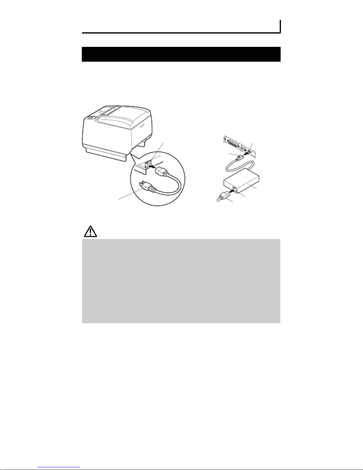
3.1 Connecting the AC Power Cord
1.
Turn off the power.
2.
For the built-in power type printer, connect the AC power cord to the AC inlet, and
insert the plug into an electric outlet.
For the AC adapter type printer, connect the cable connector of the AC adapter to
the power connector. Next, connect the AC power cord to the AC inlet, and insert
the plug into an electric outlet.
AC inlet
Cable connector
AC power cord
Built-in power supply type
AC adapter type
CAUTION
Use only an AC adapter that complies with the specified ratings.
Always hold the AC adapter’ s cable connector by the connector when removing or
inserting it.
Use an AC power source that does not also supply power to equipment that
generates electromagnetic noise.
Pulling on the AC power cord may damage it, cause a fire, electric shock, or break a
wire.
If a lightning storm is approaching, unplug the AC power cord from the electric outlet.
A lightning strike may cause a fire or electric shock.
Keep the AC power cord away from heat generating appliances. The insulation on the
AC power cord may melt and cause a fire or electric shock.
If the printer is not going to be used for a long time, unplug the AC power cord from
the electric outlet.
Place the AC power cord so that people do not trip on it.
— 16 —
Power connector
AC adapter
AC inlet
AC power cord
Page 17
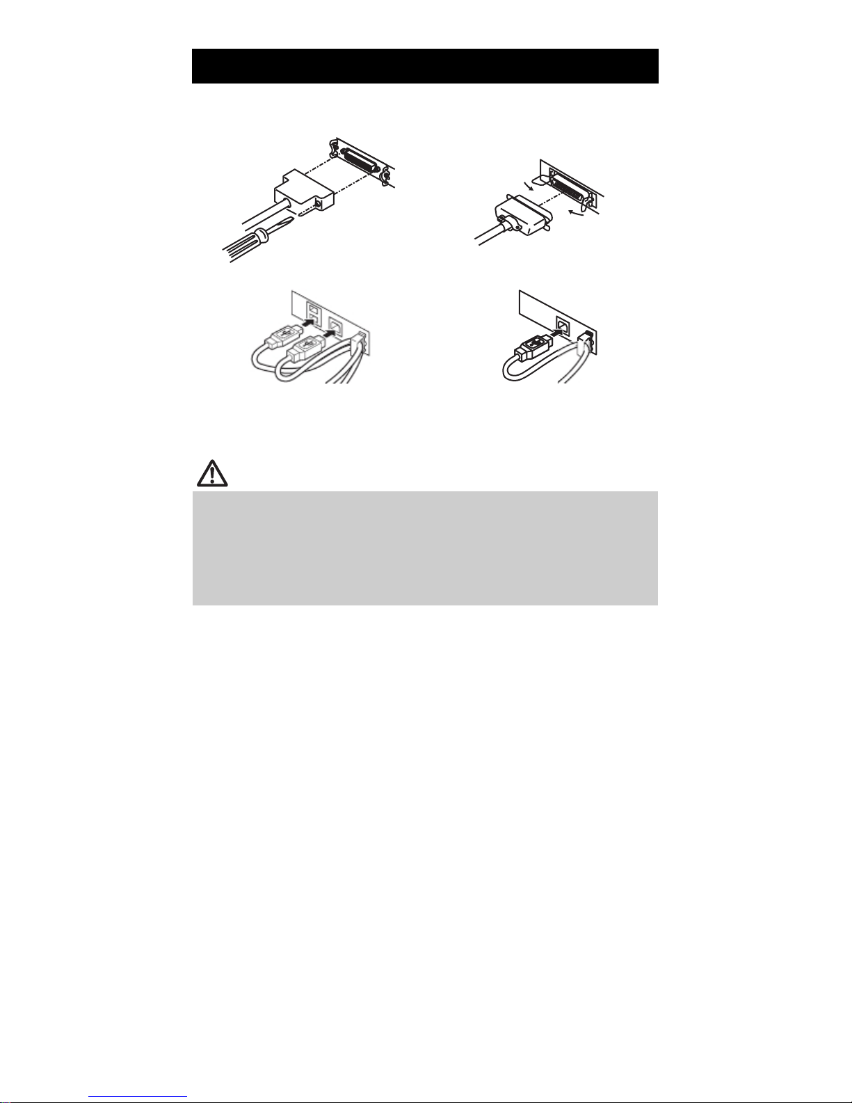
3.2 Connecting Interface Cables
1.
Turn off the power.
2.
Orient the interface cable correctly and insert it into the interface connector.
Serial interface
Parallel interface
USB interface (hub type)
Serial , Ethernet , USB interface [hub type] and Powered USB interfaces are available as
options in addition to those listed here.
USB interface
CAUTION
Always unplug the AC adapter from the printer before connecting the printer to a
Powered USB interface. Failure to do so may damage the host PC.
When disconnecting the cable, always hold the connector.
Be careful not to insert the USB interface cable into the cash drawer kick-out
connector.
To connect more than one printer to a single computer via a USB interface you must
change the serial number of the USB interface.
— 17 —
Page 18
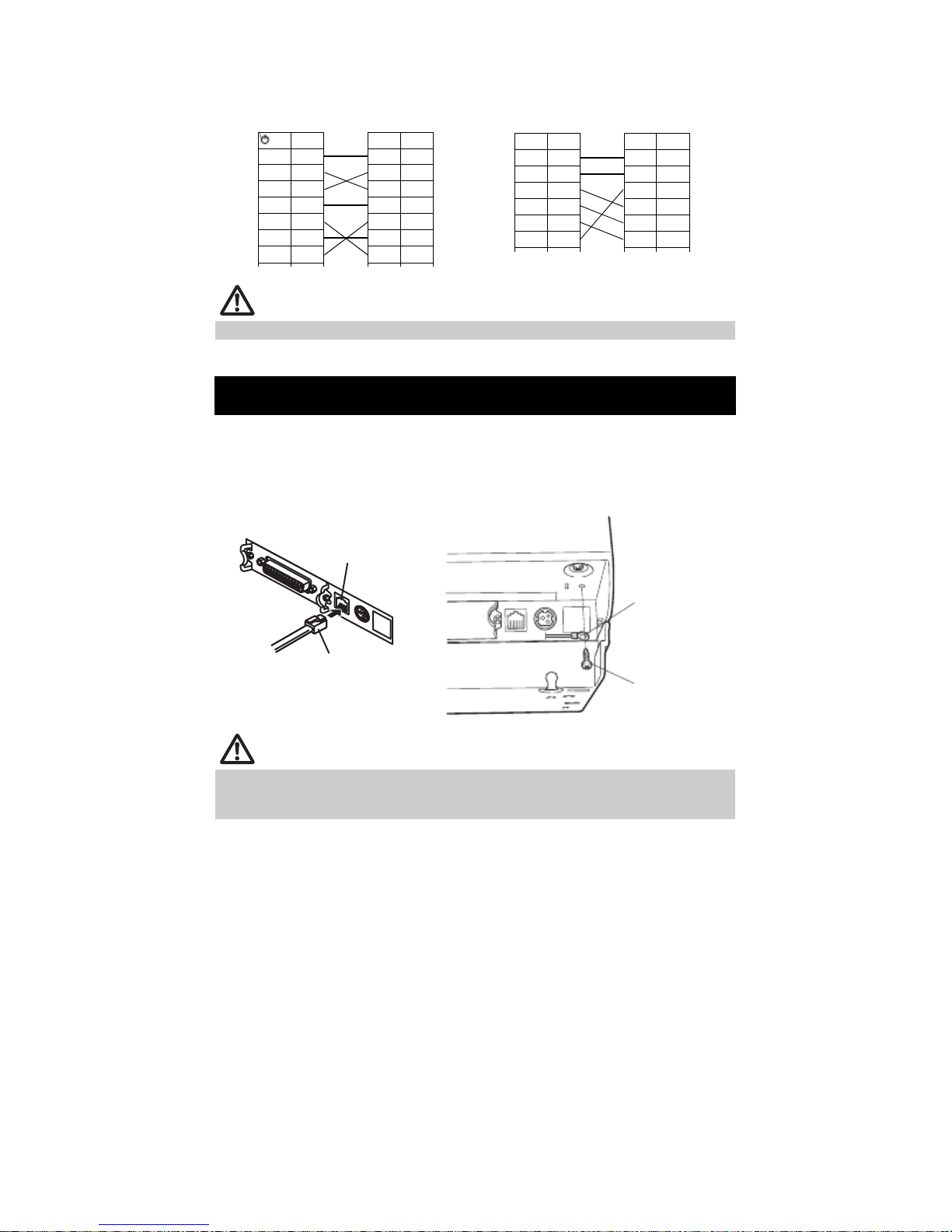
Use a serial interface cable with the connection layout shown below.
25-pin - 25-pin cable 9-pin - 25-pin cable
PC
FG 1
TXD 2
RXD 3
CTS 5
DSR 6
SG 7
DTR 20
Pin
Printer
Signal
FG 1
TXD 2
RXD 3
CTS 5
DSR 6
SG 7
DTR 20
Pin
PC
Signal
FG 1
TXD 2
RXD 3
CTS 5
DSR 6
SG 7
Pin
Printer
Signal
FG 1
TXD 2
RXD 3
CTS 5
DSR 6
SG 7
Pin
CAUTION
Place the interface cable so people do not trip on it.
3.3 Connecting the Cash Drawer
1.
Turn off the power.
2.
Confirm the orientation of the cash drawer kick-out cable connector and connect it
to the cash drawer kick-out connector at the back of the printer.
Remove the screw for the ground wire.
3.
Screw the cash drawer’ s ground wire to the body of the printer.
4.
Cash drawer kick-out
connector
Cash drawer kick-out cable
connector
Ground wire
Screw for ground
wire
CAUTION
Connect only the cash drawer kick-out cable connector to the cash drawer kick-out
connector. (Do not connect a telephone line.)
Signals cannot be output from the cash drawer kick-out connector while printing.
— 18 —
Page 19
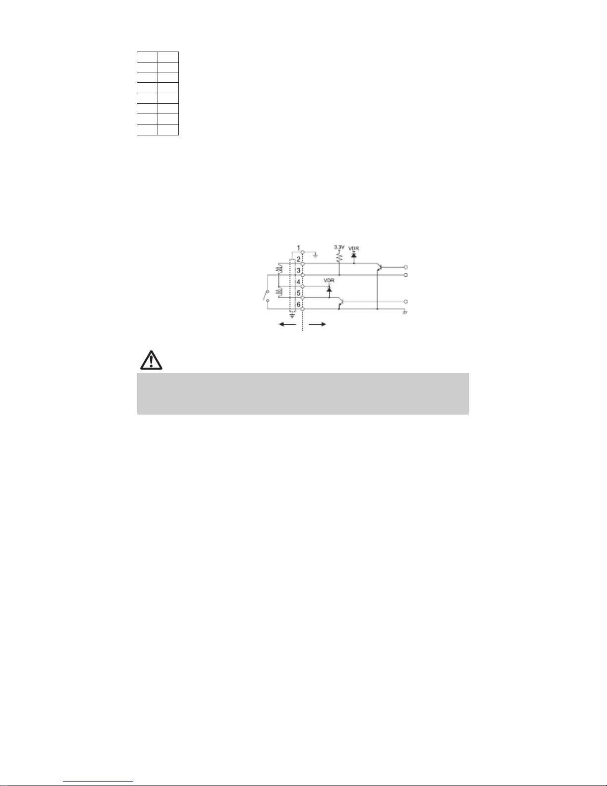
(1) Connector pin configuration
Signal
FG 1
TXD 2
RXD 3
CTS 5
DSR 6
SG 7
DTR 20
Pin
Connector used:
TM5RJ3-66 (Hirose) or
equivalent
Applicable connector:
TM3P-66P (Hirose) or
equivalent
(2) Electric characteristics
1) Drive voltage: 24 VDC
2) Drive current: Approx. 1 A max. (not to exceed 510 ms.)
3) DRSW signal: Signal levels: “ L” = 0 to 0.8 V, “ H” = 2 to 3.3 V
(3) DRSW signal
DRSW signal status can be tested with the DLE+EOT, GS+a, or GS+r
command or at pin 34 on the parallel interface port.
(4) Drive circuit
Cash drawer kick-out connector
Shielded
Cash drawer open/
close switch
Cash drawer
Printer
CAUTION
Cash drawers 1 and 2 cannot be operated at the same time.
The solenoid used for the cash drawer should be 24 ∧ or more. Do not allow the
electric current to exceed 1 A. Excessive current could damage or burn out the
circuits.
— 19 —
Page 20
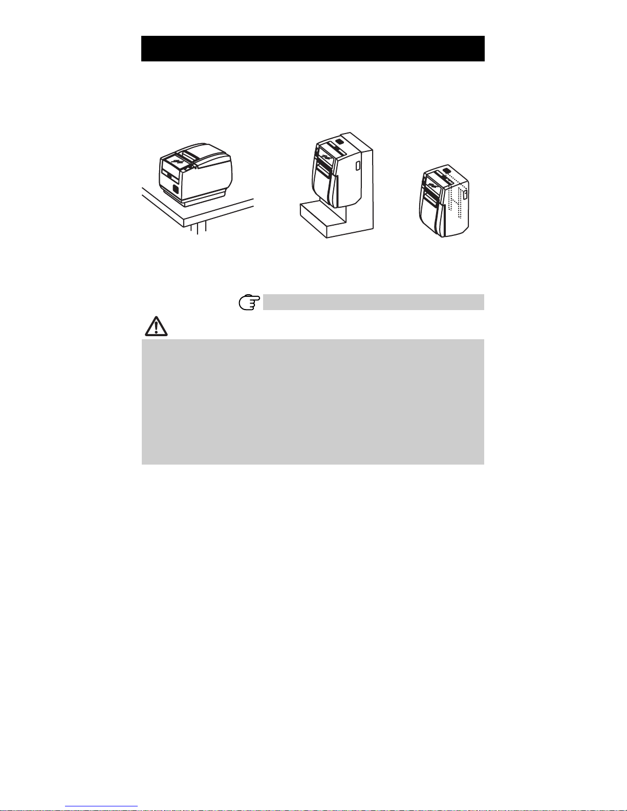
3.4 Precautions for Installing the Printer
The printer can be used horizontally, vertically, or installed on a wall. However,
the RP-3200 (built-in power supply type) cannot be used vertically or installed
on a wall.
Use the optional stand for vertical applications, and the optional brackets for
wall installations. Please refer to the manual for further details.
Horizontal position
Vertical position
Wall installation
Change the paper near-end sensor settings for vertical and wall installations.
(The factory setting for the paper near-end sensor is for horizontal installations.)
Refer to 3.7 Adjusting the Paper Near-end Sensor
CAUTION
Do not use the printer under the following conditions.
Locations subject to vibration or instability.
Locations that are very dirty or dusty
Locations where the printer is not level.
· The printer may fall and cause an injury.
· The quality of printing may deteriorate.
Oriented other than as specified.
· The printer may malfunction, be damaged, or cause an electric shock.
Precautions for horizontal installations
Do not set cutting to full cut. Doing so may cause cutter jams.
Precautions for vertical/wall installations
Adjust the paper near-end sensor.
— 20 —
Page 21
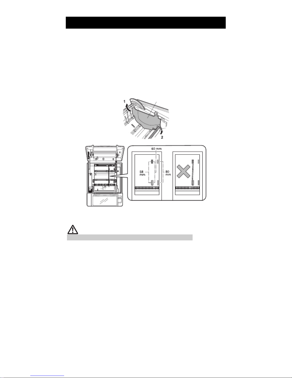
3.5 Partition for Paper Roll
Set the partition to the width of the paper roll you are loading.
The partition is set at the factory to the position shown below.
For 3-inch type: 80-mm wide paper roll
For 2-inch type: 58-mm wide paper roll
Turn off the power.
1.
Press the cover open lever.
2.
Open the paper cover.
3.
Set the partition in a slot that matches the size of the paper roll you are using.
4.
However, to use an 83-mm wide paper roll, remove the partition.
Refer to “ 5.3 Manual Setting of Memory Switches” to change the paper width
5.
settings.
Partition
*1
*1
*2
Notes:
*1: 2-inch type (58/60 mm)
*2: 3-inch type (80/83 mm)
CAUTION
Make sure the partition is not slanted when setting it for 58-mm or 60-mm paper rolls.
— 21 —
Page 22
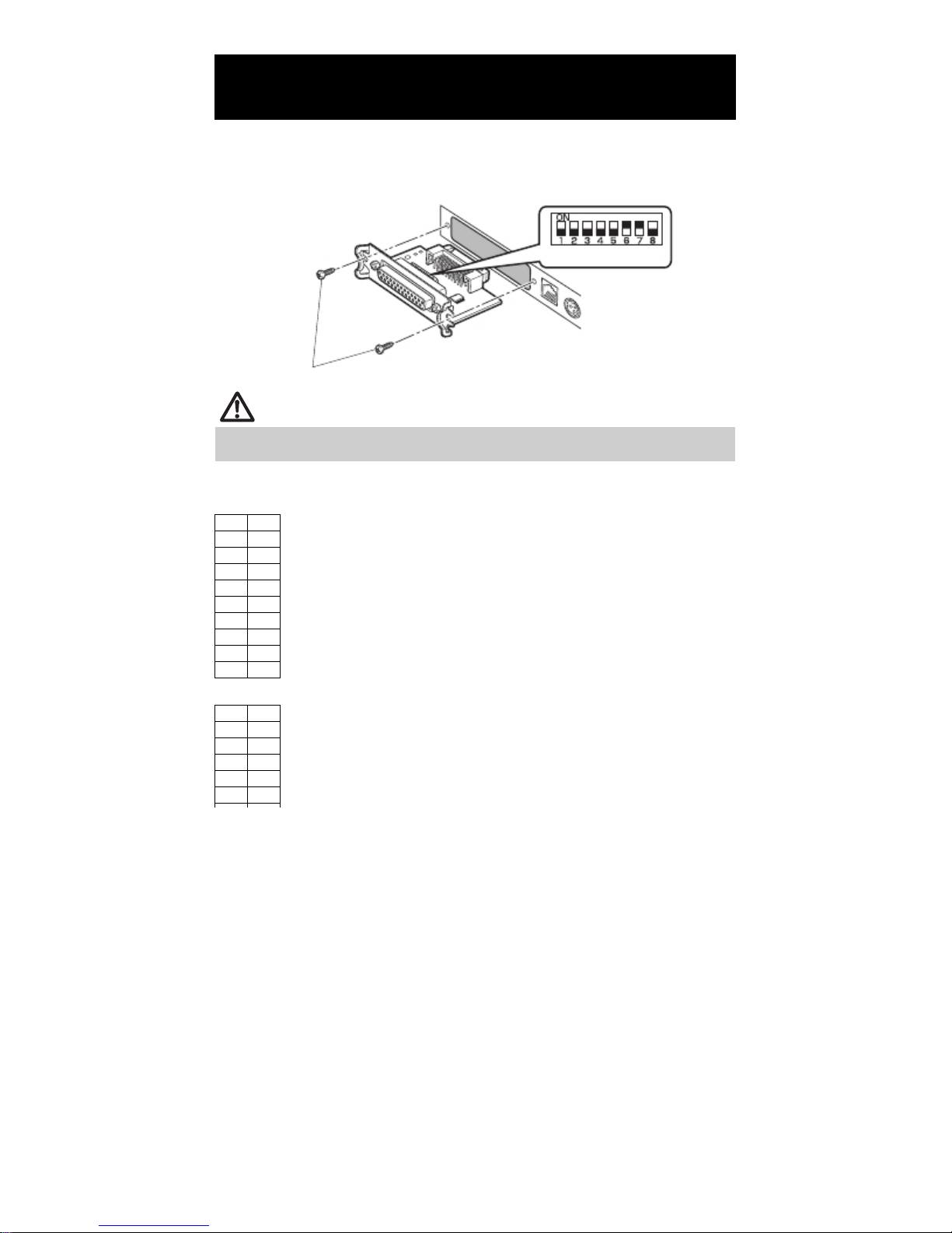
3.6 Setting the DIP Switch on the Serial
Interface Board
1.
Turn off the printer and unplug the power cord from the electric outlet.
2.
Remove the mounting screws of the serial interface board.
3.
Remove the serial interface board from the printer.
4.
Set the DIP switch according to the following table.
DIP switch
Serial interface board mounting screws
CAUTION
When setting the DIP switch, do not remove any screws except the serial interface board
mounting screws.
The function of each switch is shown below. (Shaded values are factory
settings. However, factory settings differ depending on the destination market.)
Signal
Pin
FG 1
TXD 2
RXD 3
CTS 5
DSR 6
SG 7
DTR 20
Pin
Signal
1 FG
Baud rate selection
Signal
Pin
FG 1
TXD 2
RXD 3
CTS 5
DSR 6
When switch no. 1 is set to OFF, you can use a command or a memory switch
to select 1200, 38400, 57600, or 115200 bps.
— 22 —
Page 23
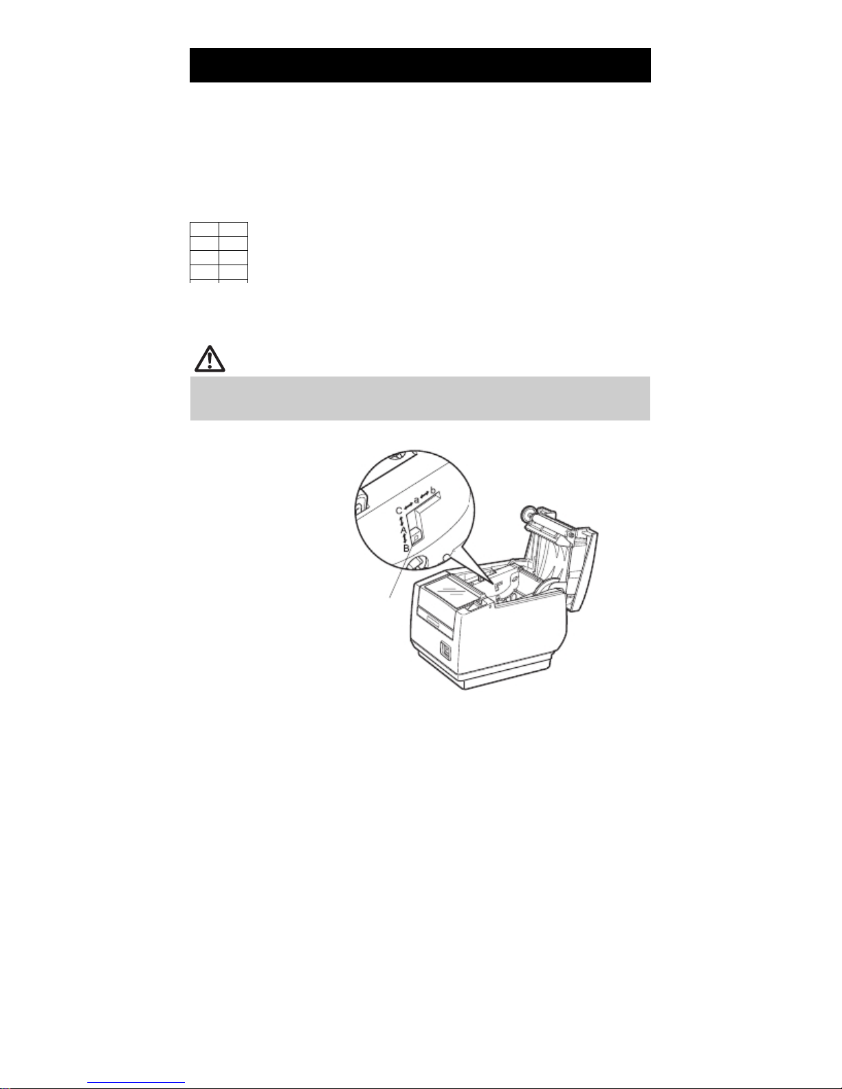
3.7 Adjusting the Paper Near-end Sensor
Change the settings of the paper near-end sensor to set the position at which
the near-end of the paper is detected.
Use a pointed object, such as a pen, to gently press the button to change the paper
1.
near-end sensor.
Press and hold down the button while moving the paper near-end sensor up, down,
2.
right and left. The sensor positions are shown below for the various diameters of the
paper roll used.
Signal
Pin
FG 1
TXD 2
RXD 3
(Unit: mm)
Note:
*: Position of sensor when shipped from factory. However, factory settings differ depending on the
destination market.
CAUTION
The amount of paper remaining on the roll (diameter of the roll) depends on the type
of paper used.
The paper roll diameters in the table are guidelines.
(“ A” and “ B” are for horizontal installations, and “ a” and “ b” are for vertical or
wall installations.)
Button to change paper
near-end sensor
— 23 —
Page 24
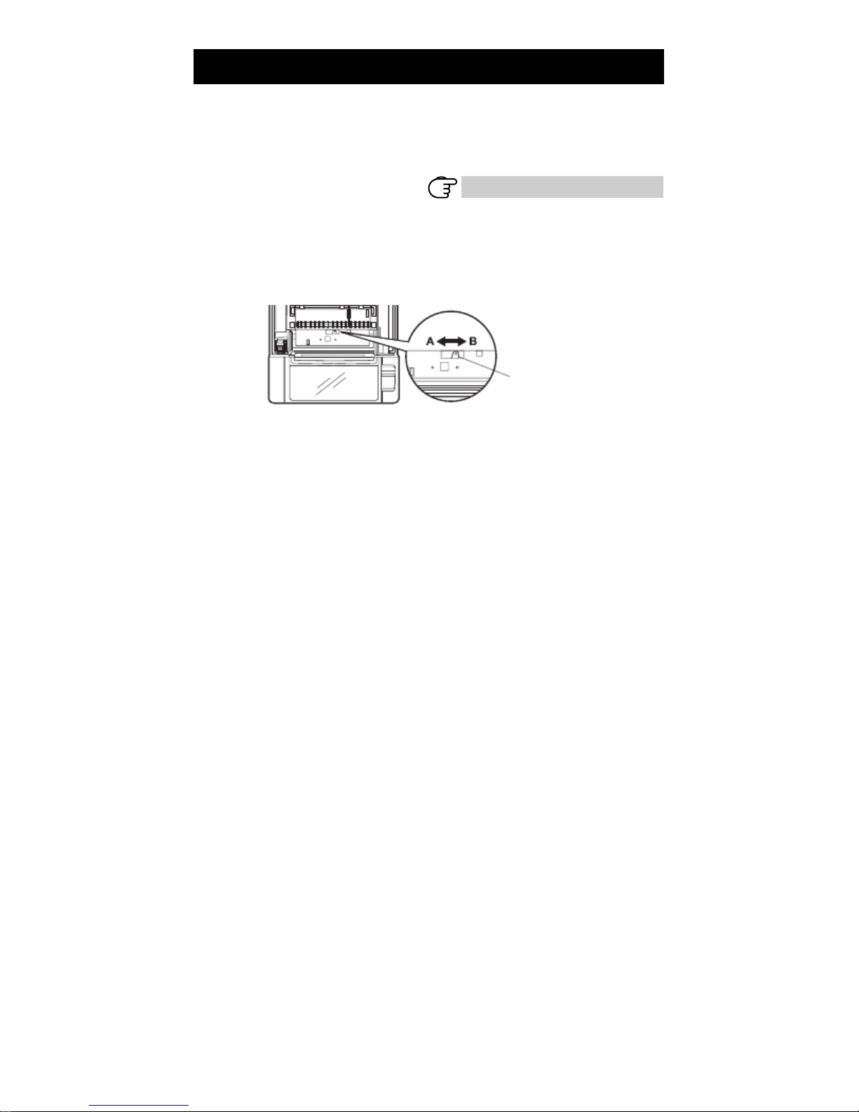
3.8 Setting Paper Thickness
Set the paper thickness selection lever to the thickness of the paper. (Thick
paper can only be used with the label-printing model)
To get the best print quality, do not change the factory settings unless printing
on thick paper or there is a problem with the print density.
1.
Turn off the power.
2.
Press the cover open lever.
3.
Open the paper cover.
4.
Set the paper thickness selection lever to A for thick paper or B for regular paper.
Gently press on the side of the lever with a pointed object, such as a pen, to
move the paper thickness selection lever.
A: Thick paper 85 ⎧m - 150 ⎧m
B: Regular paper 65 ⎧m - 85 ⎧m (Factory setting)
— 24 —
Refer to 1.3 Model Classification
Paper thickness
selection lever
Page 25
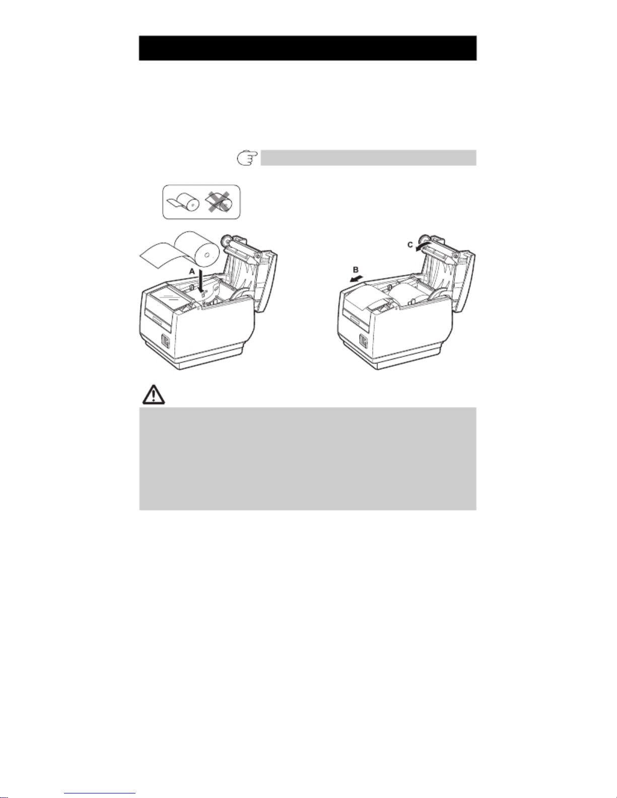
3.9 Loading Paper
1.
Press the cover open lever while the power is on.
2.
Open the paper cover.
3.
Load the paper roll so that the printable side of the paper is facing down, as shown
by arrow A.
Pull a few cm of paper straight out in the direction of arrow B.
4.
Close the paper cover in the direction of arrow C until you hear a click. Paper is fed
5.
and cut automatically, if the factory settings are set.
Refer to 5.3 Manual Setting of Memory Switches
CAUTION
Always use the specified types of paper rolls.
Confirm that the paper roll is set correctly.
If the paper is skewed and not coming straight out of the paper cover, open it and
straighten the paper.
Always pull a few cm of paper straight out of the printer if you open the paper cover
while paper is loaded.
Press on the center of the paper cover to close it securely.
Be careful of paper cuts while loading the paper.
Do not touch the print head, manual cutter, or auto cutter while the paper cover is
open. Doing so may cause a burn or cut.
— 25 —
Page 26
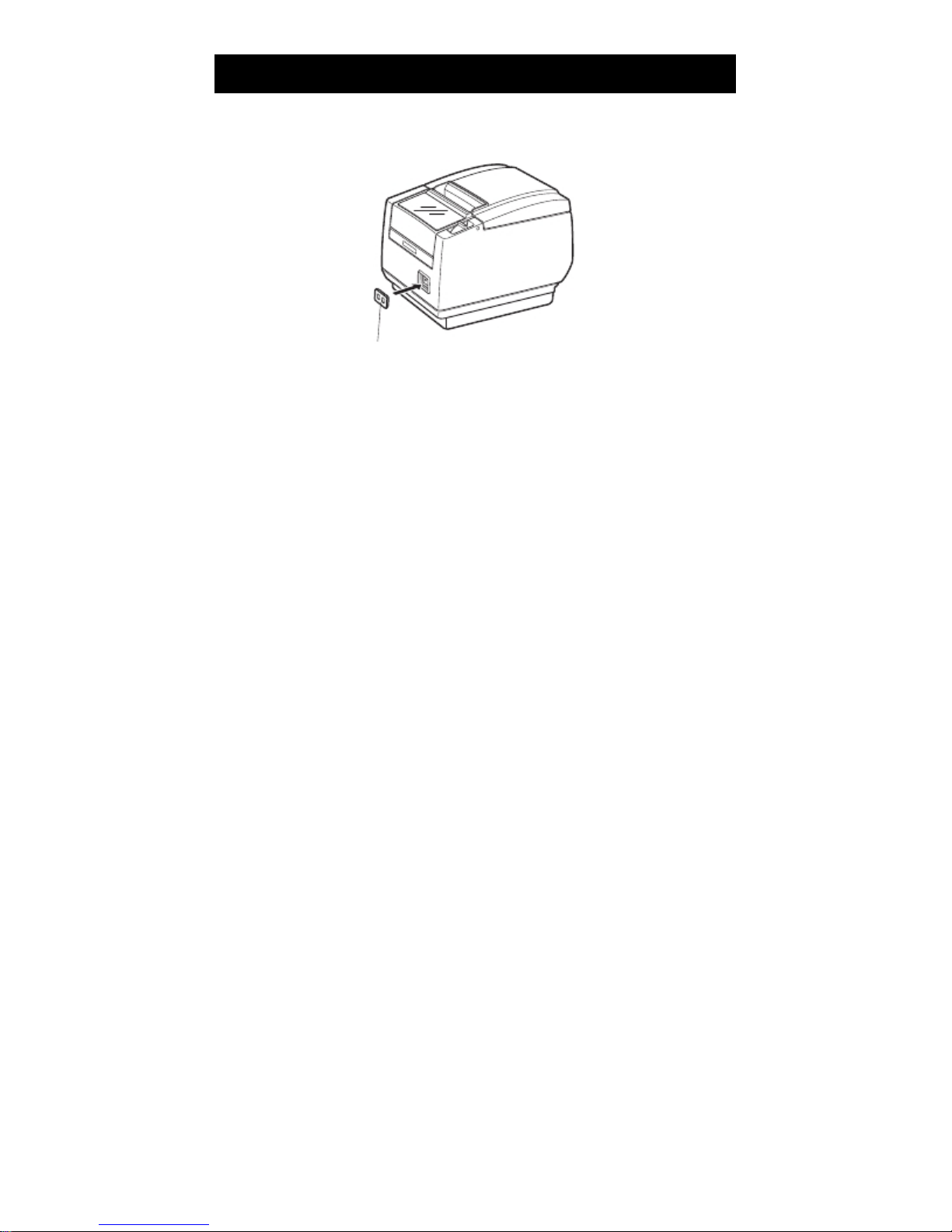
3.10 Attaching the Power Switch Cover
Attach this cover to prevent the power switch from being used.
1. Press the power switch cover onto the power switch compartment until it clicks.
Put a screwdriver or other pointed object into the grooves on the power switch
cover to remove it.
Power switch cover
— 26 —
Page 27
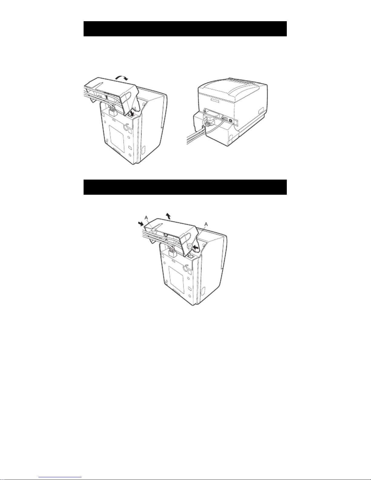
3.11 Attaching the Interface Cover
Attach the interface cover to the back of the printer.
The shape of the interface cover is different depending on the type of power
source.
1. Press the interface cover as shown in the diagram until you hear it click.
RP-3200
3.12 Removing the Interface Cover
Press in on both sides at the point indicated by A to remove the interface cover.
RP-3200
— 27 —
Page 28
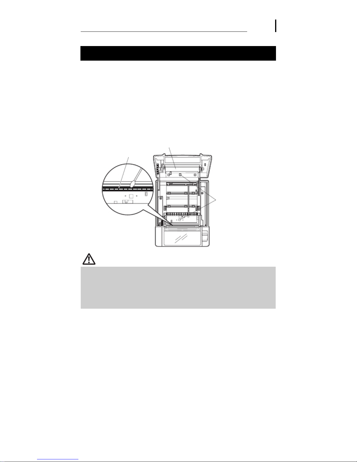
4. MAINTENANCE AND TROUBLESHOOTING
4.1 Periodic Cleaning
A dirty print head or platen may reduce printing quality or cause malfunctions.
Also, if paper dust collects on the sensor’ s protective sheet, paper cannot be
detected correctly. We recommend cleaning the printer periodically (every 2 to
3 months) as shown below.
1.
Turn off the power.
2.
Press the cover open lever.
3.
Open the paper cover. Wait a few minutes until the print head cools.
4.
Use a cotton swab dampened with ethyl alcohol to wipe off any dirt and dust that is
on the print head and platen.
Use a cotton swab dampened with a little water to wipe off the sensor’ s protective
5.
sheet.
Make sure there are no water drops on the cotton swab before wiping.
Print head
Platen
Sensor’ s protective sheet
CAUTION
The print head is hot immediately after printing. Do not touch it.
Do not touch the print head with bare hands or metal objects.
Do not use alcohol or cleansers to clean the surface of the sensor’ s protective sheet.
Doing so may fog the sensor’ s protective sheet.
Paper scraps may stick to the platen when adhesive labels are full cut depending on
the printer’ s environment, the diameter of the paper roll, and the quality of the label
backing.
— 28 —
Page 29
4.2 Clearing a Cutter Lock (1)
The ERROR LED flashes and the auto cutter blade remains extended because a
foreign object or paper jam is obstructing it.
If the ERROR LED is flashing, clear the locked cutter as shown below.
1.
Press the cover open lever while the power is on.
2.
Open the paper cover.
3.
Remove any jammed paper including any scraps of paper. (Remove the paper roll
that is loaded in the holder also.)
Reload the paper roll and close the paper cover.
4.
CAUTION
The print head is hot immediately after printing. Do not touch it.
Do not touch the print head with bare hands or metal objects.
If the paper cover does not open, the auto cutter blade is still extended (cutter
lock).
Refer to 4.3 Clearing a Cutter Lock (2)
— 29 —
Page 30
4.3 Clearing a Cutter Lock (2)
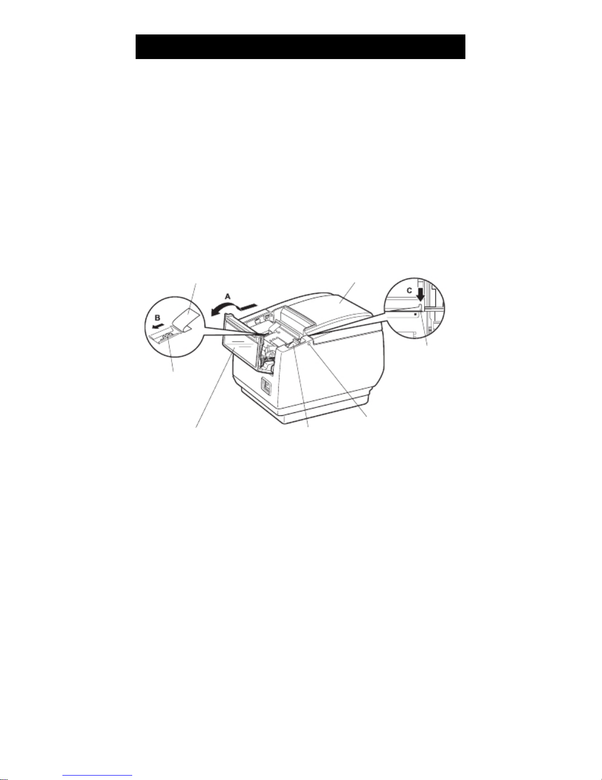
The paper cover is designed to be opened if the cutter locks by pressing the
cover open lever. If this does not open the paper cover, use the following
procedure to clear the locked cutter.
Turn off the printer and unplug the power cord from the electric outlet.
1.
Press the front cover release button with a pointed object, such as a pen, and open
2.
the front cover in the direction of arrow A.
Slide the front cover 3 to 4 mm in the direction of arrow A and rotate it forward.
Lift the protective sheet and turn the cutter gear in the direction of arrow B to return
3.
the auto cutter to a position where the paper cover can be opened.
Turn the cutter gear until the auto cutter blade retracts in the direction of arrow C. If
the blade of the auto cutter does not move when you turn the cutter gear in the
direction of arrow B, turn it in the other direction.
Press the cover open lever.
4.
Open the paper cover.
5.
Remove whatever caused the cutter to lock.
6.
Close the front cover.
7.
Rotate the front cover in the opposite direction of arrow A and then slide it until it
clicks.
Load a paper roll and close the paper cover.
8.
Insert the power cord plug into an electric outlet and turn the power on.
9.
Check that the POWER LED lights.
Protective sheet
Cutter gear
Paper cover
Auto cutter blade
Front cover
Cover open lever
Front cover release button
— 30 —
Page 31
CAUTION
Before starting to do maintenance work, be sure to turn off the printer and unplug the
power cord from the electric outlet.
Be careful not to touch the manual cutter while the front cover is open.
Be careful not to touch the opening for the auto cutter while the paper cover is open.
The print head is hot immediately after printing. Do not touch it.
Do not touch the print head with bare hands or metal objects.
If the above procedure does not retract the auto cutter, contact your dealer.
4.4 Self-printing
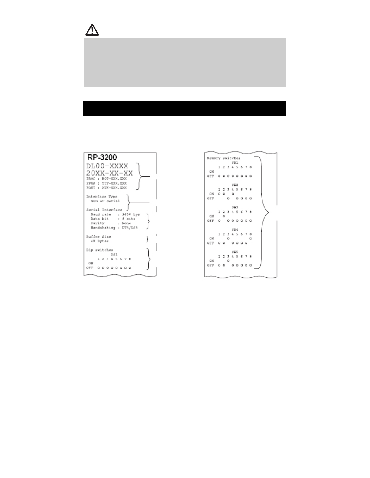
While paper is loaded, press and hold the FEED button while turning the power
on. Hold the FEED button down for about one second and then release it to start
self-printing. The printer prints its model name, version, DIP switch settings,
memory switch settings, and a list of built-in fonts.
Note:
*: Printers with a USB interface do not have DIP switches, so the DIP switches all appear off on the
self-printing printout.
Firmware version
Interface
Serial communication
status
(USB or Serial interface
models only)
Buffer size
DIP switch settings*
(USB or Serial interface
models only)
— 31 —
Memory
switch
setting
Page 32

4.5 Hexadecimal Dump Printing
Print received data in hexadecimal. If problems such as missing or duplicated
data occur, this function allows you to check whether or not the printer is
receiving data correctly.
How to do hexadecimal dump printing
1.
Load paper.
2.
While the paper cover is open, press and hold the FEED button while turning the
power on, and then close the paper cover.
The printer prints “ HEX dump print mode” followed by the received data printed in
3.
hexadecimal numbers and some characters.
How to stop hexadecimal dump printing
Do one of the following to stop printing.
Press the FEED button three times in a row
Turn off the power
Receive a reset command from an interface
CAUTION
The printer prints “ .” if there is no character corresponding to the data.
None of the commands function during hexadecimal dump printing.
If print data does not cover a complete line, press the FEED button to advance the
paper.
Print example
HEX dump print mode
61 62 63 64 65 66 67 0A 0D 0D 0D 0D abcdefg.....
0D 0D 0D .....
— 32 —
Page 33

4.6 Error Messages
Paper-end
The end of the roll of paper is detected at two stages, paper near-end and
paper-end.
When paper near-end is detected, the PAPER LED lights. Prepare a new paper
roll.
When paper end is detected, the PAPER LED and ERROR LED light. Load a
new paper roll.
Paper cover open
Do not open the paper cover during printing. If the paper cover is opened, the
ERROR LED lights or flashes. Check the paper and always pull a few cm of
paper straight out of the printer before closing the paper cover. Printing
resumes. Sending a command to resume printing may be required depending
on the memory switch setting.
Cutter locked
If the auto cutter cannot move because of a paper jam or something else, the
ERROR LED flashes. Remove the cause of the trouble and press the FEED
button. If the auto cutter still does not operate and the paper cover does not
open, refer to “ 4.3 Clearing a Cutter Lock (2)” .
Refer to 4.3 Clearing a Cutter Lock (2)
Print head hot
When you print dense characters, dark images, or for an extended time in a
hot environment, the print head temperature increases. If the print head
exceeds a specified temperature, the printer stops printing and waits for the
print head to cool. When this happens, the ERROR LED flashes. Printing
resumes automatically when the print head cools.
— 33 —
Page 34

The status display for various messages is shown below.
Signal
Pin
FG 1
TXD 2
RXD 3
CTS 5
DSR 6
SG 7
DTR 20
Pin
Signal
1 FG
2 TXD
3 RXD
4 RTS
6 DSR
7 SG
20 DTR
Pin
Signal
2 TXD
3 RXD
4 RTS
6 DSR
Notes:
*1: If the paper cover or front cover is open in standby.
*2: If the paper cover or front cover is open when printing or feeding paper.
*3: Buzzer sounds when MSW5-1 (buzzer setting) is set to ON.
— 34 —
Page 35
5. OTHER
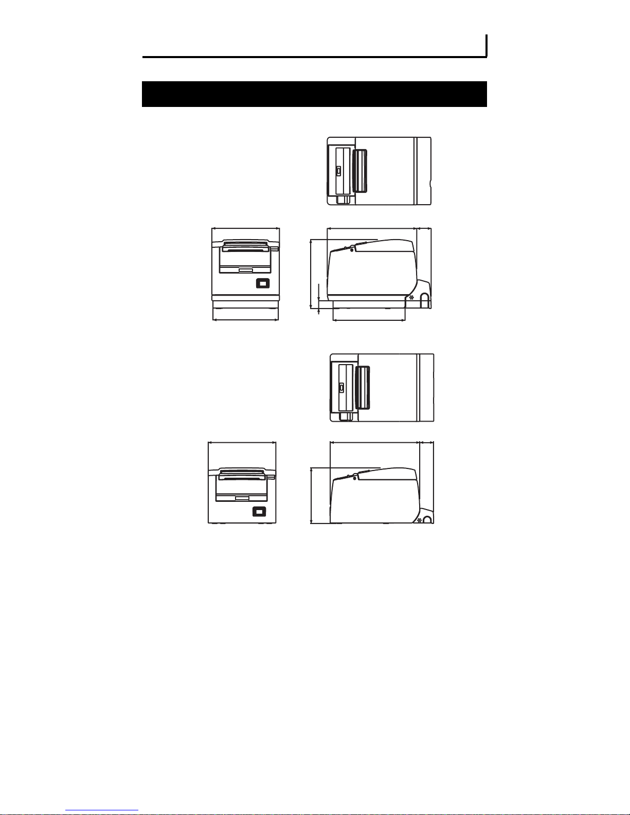
5.1 External Views and Dimensions
145
140
Built-in power supply type
148
16
145
192
155
192
120
AC adapter type
— 35 —
31
31
(Unit: mm)
Page 36
⎞
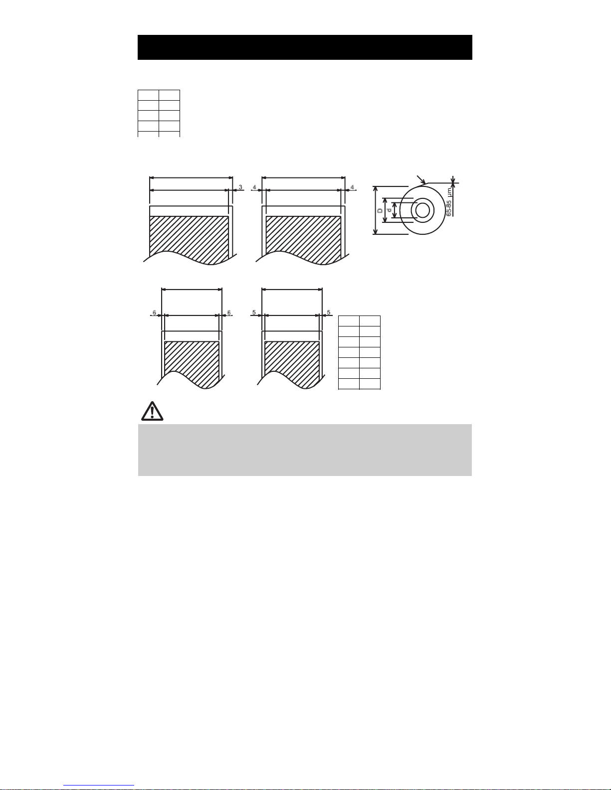
5.2 Printing Paper
Use the paper shown in the following table or paper of the same quality.
Signal
Pin
FG 1
TXD 2
RXD 3
(Unit: mm)
Paper width 83 +0
Maximum print area 80
-1
Paper width 60 +0
Maximum print area 48
(Initial setting)
-1
Paper width 80 +0
Maximum print area 72
Paper width 58 +0
Maximum print area 48
(Initial setting)
-1
Printable side
80 or less
-1
Signal
Pin
FG 1
TXD 2
RXD 3
CTS 5
DSR 6
SG 7
CAUTION
Use paper that is wound as follows:
Not creased and fits tight to the core.
Not folded.
Not glued to the core.
Rolled with the printable side out.
— 36 —
Page 37

5.3 Manual Setting of Memory Switches
Memory switches are used to set various printer settings. The memory switches
can be set manually (set by hand on the printer) or by commands. This section
explains how to perform manual settings.
For information on how to set the memory switches using commands, please
refer to the Command Reference.
Quick setting mode
The settings for the memory switches for a replacement printer’s manufacturer,
model, paper width, and character spacing can be set at the same time to the
optimum settings.
Do the settings while confirming the selected items on the printout.
1.
Load paper.
2.
While the paper cover is open, press and hold the FEED button while turning the
power on.
Press the FEED button three times and close the paper cover.
3.
The printer enters memory switch quick setting mode.
The selectable item “Manufacturer” and the selection are printed.
4.
Press the FEED button.
A selection is printed in order through the cycle each time the FEED button is pressed.
Press the FEED button until the selection you want is printed.
Press the FEED button for at least two seconds.
5.
The selection is set.
If there is another selectable item, it and the selection are printed.
Repeat steps 4 and 5 to select and set the printer’s model, paper width, character
6.
spacing (EPSON T88 only).
When all the items are set, “Save To Memory“ is printed.
Press the FEED button for at least two seconds.
7.
The changed memory switch settings are saved and a list of them is printed.
The printer exits quick setting mode when printing is finished.
Manufacturer TVS-E
Selectable item
Selection
— 37 —
Page 38
Individual setting mode
Set the memory switches individually.
Do the settings while confirming the memory switch function and settings on
the printout.
1.
Load paper.
2.
While the paper cover is open, press and hold the FEED button while turning the
power on.
Press the FEED button twice and close the paper cover.
3.
The printer enters the mode for setting memory switches individually.
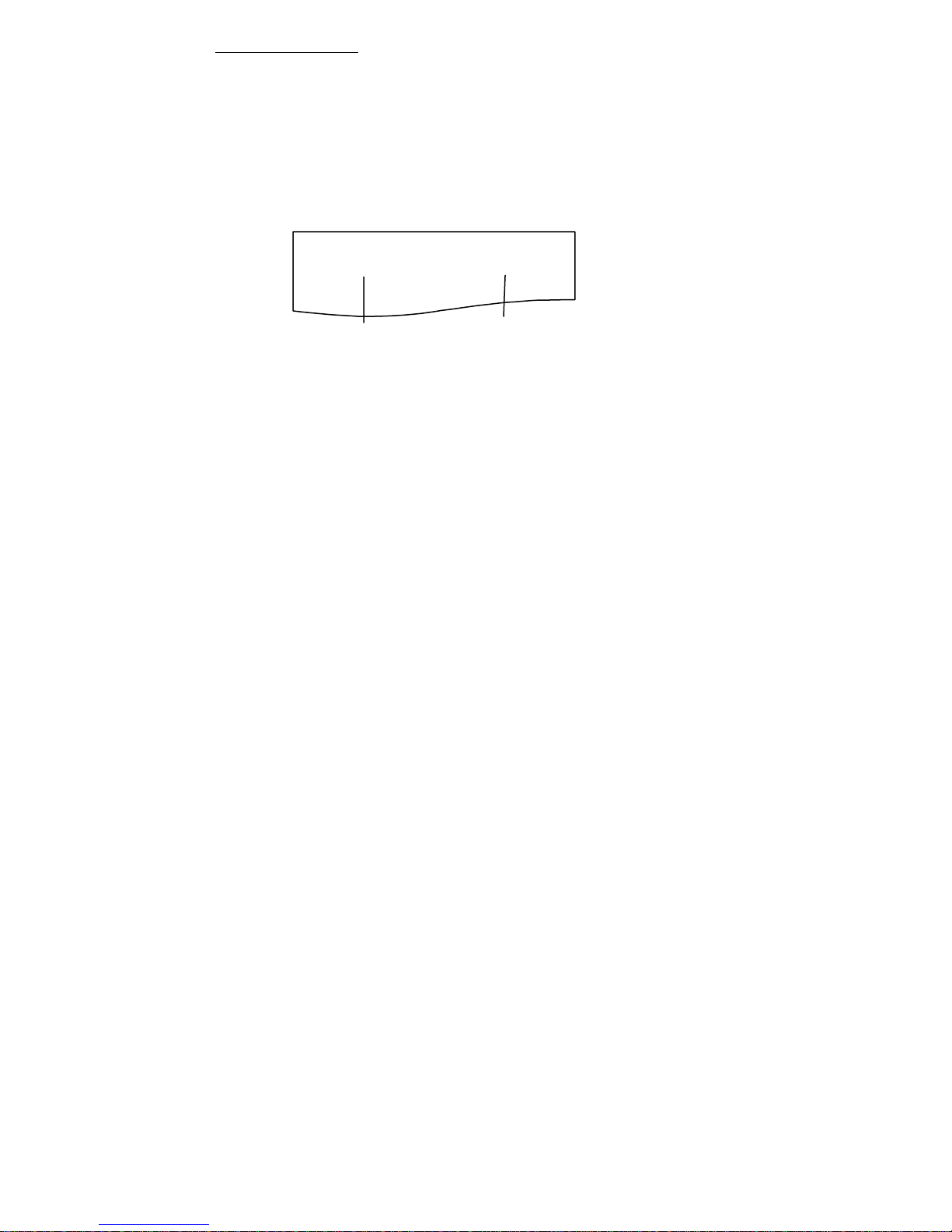
The printer prints “Memory SW (1)” and the current setting, 0 (off) or 1 (on).
(The current settings for memory switches 7 to 10 are not printed.)
Memory SW (1) 00000000
Current memory switch
4. Press the FEED button.
The list of memory switches cycles through in order from “ Memory SW (1)”
“ Memory SW (2)” ... “ Memory SW (10)” “ Save To Memory” “ Memory SW
(1)” each time the FEED button is pressed.
Press the FEED button until the number for the memory switch you want to change is
printed.
-38-
Current setting
Page 39

5.
Press the FEED button for at least two seconds.
A setting for the memory switch is printed, through the cycle, each time the FEED
button is pressed for at least two seconds.
Press the FEED button for at least two seconds to cycle through the list until the
function of the memory switch you want to change is printed.
Memory switch function
6. Press the FEED button.
A setting is printed each time the FEED button is pressed in order through the cycle.
When the current settings are printed, the ERROR LED lights.
Press the FEED button until the setting you want is printed.
7. Press the FEED button for at least two seconds.
The selected settings are set.
The next memory switch function and settings are printed.
8. Repeat steps 5 to 7 to change different functions for the current memory switch
number.
9. Open the paper cover and close it.
The changed memory switch settings are printed.
10. Repeat steps 4 to 9 to change functions for a different memory switch number.
11. Press the FEED button until “ Save To Memory” is printed.
12. Press the FEED button for at least two seconds.
The changed memory switch settings are saved and a list of them is printed.
The printer exits individual setting mode when printing is finished.
Current setting
Memory switch initialization
Set all the memory switches to the factory settings.
Do steps 1 through 3 of the procedure to enter individual setting mode.
1.
Press the FEED button until “ Save To Memory” is printed.
2.
Open the paper cover.
3.
Press the FEED button for at least two seconds.
4.
All memory switches change to the factory settings.
Close the paper cover.
5.
— 39 —
Page 40
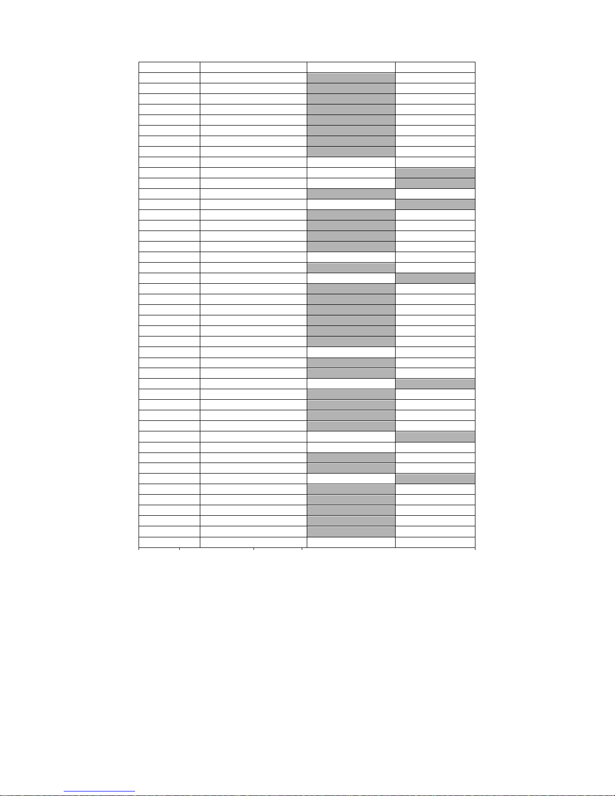
The function of each memory switch is shown in the following table. (Shaded
values are factory settings.)
Switch no. Function OFF ON
MSW1-1 Power ON Info Valid Not Send
MSW1-2 Buffer Size
MSW1-3 Busy Condition
MSW1-4 Receive Error
MSW1-5 CR Mode
MSW1-6 Reserved
MSW1-7 DSR Signal
MSW1-8 Init Signal
MSW2-1 Reserved — Fixed
MSW2-2 Auto Cutter Invalid
* MSW2-3 Spool Print
MSW2-4 Full Col Print LineFeed
MSW2-5 Resume aft PE
MSW2-6 Reserved
MSW2-7 Reserved
MSW2-8 PNE Sensor
MSW3-1 Resume Cttr Err Valid Invalid
MSW3-2 PE signal by PNE Valid
MSW3-3 Parallel 31 Pin
MSW3-4 Reserved
MSW3-5 Reserved
MSW3-6 Reserved
MSW3-7 CBM1000 Mode
MSW3-8 Resume Open Err
MSW4-1 Reserved Fixed —
MSW4-2 Reserved Fixed —
MSW4-3 Feed&Cut at TOF Invalid Valid
MSW4-4 Reserved Fixed —
MSW4-5 Reserved Fixed —
MSW4-6 Reserved Fixed —
MSW4-7 Reserved Fixed —
MSW4-8 Partial Only Invalid Valid
MSW5-1 Buzzer Valid Invalid
MSW5-2 Line Pitch 1/360 1/406
MSW5-3 USB Mode Virtual COM Printer Class
MSW5-4 Reserved Fixed —
MSW5-5 Reserved Fixed —
MSW5-6 Reserved Fixed —
MSW5-7 Reserved Fixed —
MSW5-8 Reserved Fixed —
4K bytes
Full/Err
Print“ ?”
Ignored
Fixed
Invalid
Invalid
Invalid
Next
Fixed
Fixed
Valid
Valid
Fixed
Fixed
Fixed
Invalid
Close
45 bytes
Full
No Print
Valid
Valid
Valid
Valid
WaitData
Top
Invalid
Invalid
Invalid
Valid
Command
LF
—
—
—
—
—
—
— 40 —
Page 41
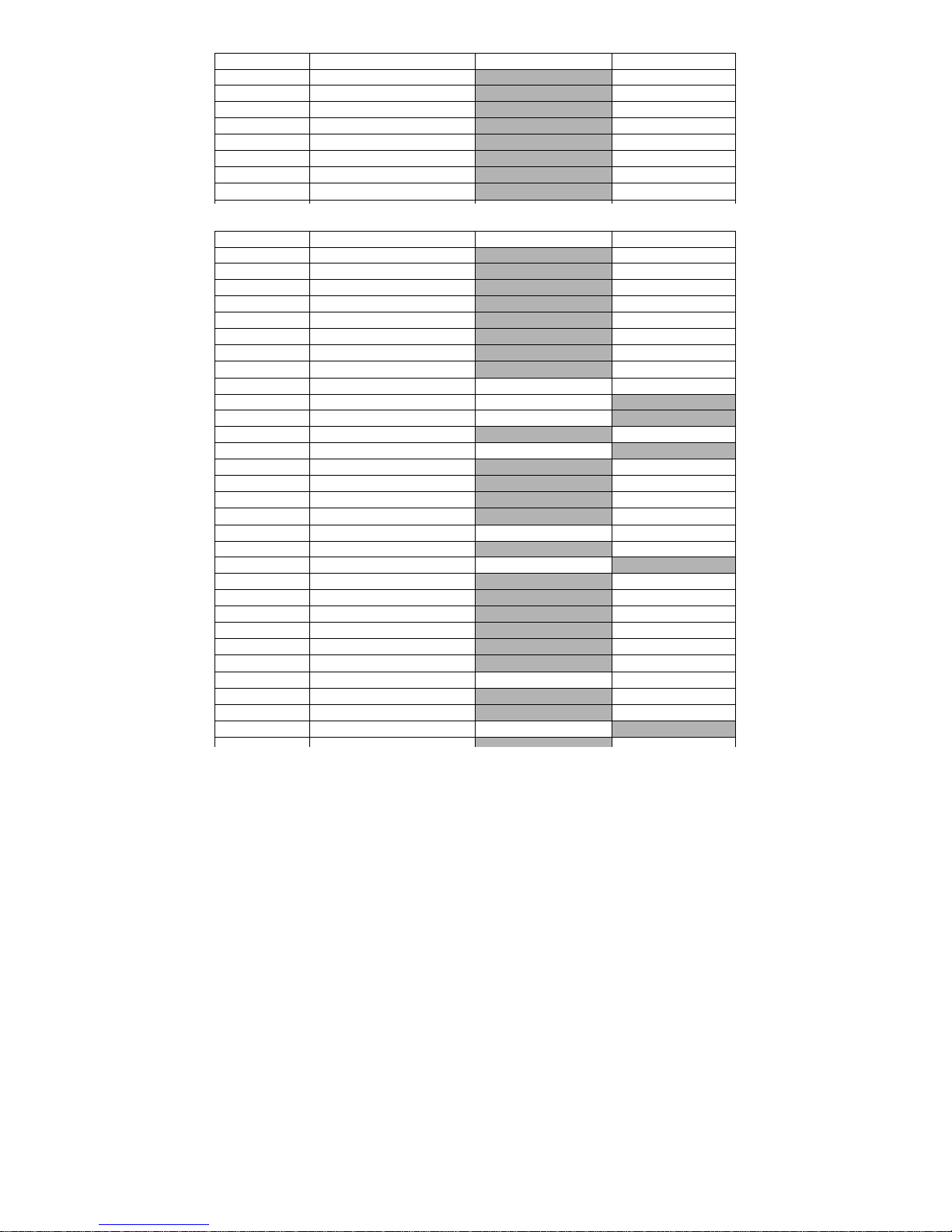
Switch no. Function OFF ON
MSW1-1 Power ON Info Valid Not Send
MSW1-2 Buffer Size
MSW1-3 Busy Condition
MSW1-4 Receive Error
MSW1-5 CR Mode
MSW1-6 Reserved
MSW1-7 DSR Signal
MSW1-8 Init Signal
4K bytes
Full/Err
Print“ ?”
Ignored
Fixed
Invalid
Invalid
45 bytes
Full
No Print
LF
—
Valid
Valid
Switch no. Function OFF ON
MSW1-1 Power ON Info Valid Not Send
MSW1-2 Buffer Size
MSW1-3 Busy Condition
MSW1-4 Receive Error
MSW1-5 CR Mode
MSW1-6 Reserved
MSW1-7 DSR Signal
MSW1-8 Init Signal
MSW2-1 Reserved — Fixed
MSW2-2 Auto Cutter Invalid
* MSW2-3 Spool Print
MSW2-4 Full Col Print LineFeed
MSW2-5 Resume aft PE
MSW2-6 Reserved
MSW2-7 Reserved
MSW2-8 PNE Sensor
MSW3-1 Resume Cttr Err Valid Invalid
MSW3-2 PE signal by PNE Valid
MSW3-3 Parallel 31 Pin
MSW3-4 Reserved
MSW3-5 Reserved
MSW3-6 Reserved
MSW3-7 CBM1000 Mode
MSW3-8 Resume Open Err
MSW4-1 Reserved Fixed —
MSW4-2 Reserved Fixed —
MSW4-3 Feed&Cut at TOF Invalid Valid
-
Note:
*: If print data is very dense, the print head is hot, data transmission is slow, or some other conditions,
the motor and printing may occasionally stop which causes white stripes in the printout. To print
high-density data, set MSW2-3 (Spool Print) to ON to reduce striping, although this increases the
time before printing starts.
For a serial interface, increase the transmission speed to prevent the motor from stopping.
-41-
4K bytes
Full/Err
Print“ ?”
Ignored
Fixed
Invalid
Invalid
Invalid
Next
Fixed
Fixed
Valid
Valid
Fixed
Fixed
Fixed
Invalid
Close
45 bytes
Full
No Print
LF
—
Valid
Valid
Valid
Valid
WaitData
Top
—
—
Invalid
Invalid
Invalid
—
—
—
Valid
Command
—
 Loading...