

Page 1

st
Revision:- Rev. 1, 1 Aug'2018 onwards
TVS Apache RR 310
Owner’s Manual
Part number:- N7210130
Revision :- Rev. 1, Aug 2018
Page 2

st
Revision:- Rev. 1, 1 Aug'2018 onwards
Page 3

st
Revision:- Rev. 1, 1 Aug'2018 onwards
FOREWORD
Foreword
Dear Racer,
Thank you for choosing the TVS Apache
RR 310. The most powerful and technologically
advanced Apache yet.
The precision racer has been shaped in the
wind tunnel, honed on the dyno and perfected
over countless laps on the racetrack. The
flagship racer is the culmination of 35 years of
TVS Racing heritage, the racing prowess
reflects in every straight and every corner of the
track. The Apache RR 310 has been crafted to
be the ultimate racer.
This ma n ual expl a ins the features and
operations of your TVS Apache RR 310. Please
read it carefully and follow the instructions to
enjoy the racing experience.
To prolong your journey on the TVS Apache
RR 310, we urge you to get your TVS Apache
RR 310 services only at TVS Motor Company
Authorized Dealers.
Here’s to breaking lap records on your Apache
RR 310.
TVS Motor Company Limited
I
Page 4

st
Revision:- Rev. 1, 1 Aug'2018 onwards
In case, you need any clarification or Service Assistance, please contact our Dealer
Dealer code, name .......................................................................................................................................................
Address ...........................................................................................................................................................................
............................................................................................................................................................................................
............................................................................................................................................................................................
Contact person name and mobile no. (Sales)
............................................................................................................................................................................................
Contact person name and mobile no. (Service)
............................................................................................................................................................................................
Email id.............................................................................................................................................................................
Or
TVS Motor Company’s Area Offices (flip over for addresses)
Or
Toll free number : 1800-258-7111
Email : [email protected]
CONTACT(S) FOR SUPPORT
Contact(s) for Support
II
Page 5

st
Revision:- Rev. 1, 1 Aug'2018 onwards
Contact at Our Area Offices
TAMILNADU-1
1. TVS Motor Company Limited
V Floor, Gee Gee Universal,
No. 2, MC Nichols Road,
Chetpet, Chennai - 600 031.
Phone : 044-28361651/28361654
Email : [email protected]
TAMILNADU-2
2. TVS Motor Company Limited
No.10, 2nd floor,
Shree Shanmugapriya Towers,
Kannuswamy Street,
Behind Hotel Annapoorna,
R S Puram, Coimbatore - 641 002.
Phone : 0422-4350060/2541035
Email : [email protected]
TAMILNADU-3
3. TVS Motor Company Limited
D-09, Srinidhi Block, Agrini Apartments,
Andalpuram, TPK Road,
Madurai - 625 003.
Phone : 0452-4208690
Email : [email protected]
TAMILNADU-4 & 5
4. TVS Motor Company Limited
No. 37, 1st Floor, Mian Road,
West Brindavan,
Near Hotel Le Royal Park,
Puducherry - 605 103.
Phone : 0413-2247655
Email : [email protected]
KERALA
5. TVS Motor Company Limited
Ambady Towers, Second Floor,
Door No. 27/631, A6,
Edappally, Pookkattupady Road,
Edappally PO., Cochin - 682 024.
Phone : 0484-2544578/2556938
Email : [email protected]
ANDHRA PRADESH-1 & 3
6. TVS Motor Company Limited
No. D-19, 302, 3rd floor, Gayathri Arcade,
Vikrampuri, Secunderabad - 500 003.
Phone : 040-27840590/27844419
Email : [email protected]
CONTACT(S) FOR SUPPORT
Area Office Address
III
Page 6

st
Revision:- Rev. 1, 1 Aug'2018 onwards
ANDHRA PRADESH-2
7. TVS Motor Company Limited
Door No. 58-2-35, NCK Plaza,
Near NTR Circle, Patamata,
Vijayawada - 520 010.
Phone : 0866-6575100
Email : [email protected]
KARNATAKA-1
8. TVS Motor Company Limited
No. 600, Anand Surya, 2nd Floor, 15th Cross, 6th
Phase, JP Nagar, Opp. BMTC Stop,
Bangalore - 560 078.
Phone : 080-26653433
Email : [email protected]
KARNATAKA-2 & GOA
9. TVS Motor Company Limited
No. 122/111 B, PDP Plaza, 3rd floor,
New Cotton Market, Karnataka Bank Road,
Hubli - 580 029.
Phone : 0836-4250617/4250618
Email : [email protected]
MAHARASHTRA-1, 2 & 4
10. TVS Motor Company Limited
No. 401, 4th floor, The Chambers, Plot No. 4/12/3,
Near Ganpati Chowk,
Viman Nagar, Pune - 411 014.
Phone : 020-26632111/26632110
Email : [email protected]
MAHARASHTRA-3
11. TVS Motor Company Limited
Plot No. 206, House No. 241,
Ward No. 73, 1st floor,
West High Court Road,
Dharampeth, Nagpur - 400 010.
Phone : 0712-2569932
Email : [email protected]
[email protected]
CHATTISGARH
12. TVS Motor Company Limited
No. 627-628, Magneto Offizo,
Magneto the Mall, Labhandi,
GE Road, Raipur - 492 010.
Phone : 0771-4260006
Email : [email protected]
MADHYA PRADESH-1
13. TVS Motor Company Limited
211-212, 2nd floor,
Chinar Incube Business centre,
Chinar Fortune City,
Near Vrindavan Dhaba,
Hoshangabad Road, Bhopal - 462 026.
Phone : 0755-2499406/2499306
Email : [email protected]
CONTACT(S) FOR SUPPORT
Area Office Address
IV
Page 7

st
Revision:- Rev. 1, 1 Aug'2018 onwards
MADHYA PRADESH-2
14. TVS Motor Company Limited
301, 3rd floor, Shagun Arcade,
Vijay Nagar circle, A B Road,
Indore - 452 010.
Phone : 9893028266
Email : [email protected]
GUJARAT-1 & 2
15. TVS Motor Company Limited
109, Ayana Complex,
Opp. Suvarna Villa Bungalows,
100 ft Thaltej Hebbatpur road,
Off : S.G. highway, Thaltej,
Ahmedabad - 380 054.
Phone : 079-65443748
Email : [email protected]
UTTAR PRADESH-EAST, CENTRAL & HILLS
16. TVS Motor Company Limited
1st floor, Cyber Tower, TC-34/V-2,
Vibhuti Khand, Gomti Nagar,
Lucknow - 226 010.
Phone : 0522-4918300/4918301
Email : [email protected]
[email protected]
UTTAR PRADESH-WEST
17. TVS Motor Company Limited
D-3 & D-4, 2nd floor,
Sector - 10, Noida,
Uttar Pradesh - 201 301
Phone : 011-29834640/29834773
Email : [email protected]
DELHI & HARYANA
18. TVS Motor Company Limited
D-3 & D-4, 2nd floor,
Sector - 10, Noida,
Uttar Pradesh - 201 301
Phone : 011-29834640/29834773
Email : [email protected]
PUNJAB, HIMACHAL PRADESH, JAMMU &
KASHMIR
19. TVS Motor Company Limited
SCF- 10-11, Kalghaidhar Enclave,
Baltana Road, Zirakpur,
District Mohali - 140 603.
Phone : 01762-511659/511661
Email : [email protected]
Area Office Address
CONTACT(S) FOR SUPPORT
V
Page 8

st
Revision:- Rev. 1, 1 Aug'2018 onwards
Area Office Address
VI
CONTACT(S) FOR SUPPORT
RAJASTHAN-1
20. TVS Motor Company Limited
Plot No. 17-18,
2nd floor of National Motors building,
Jhotwara Industrial Area,
Jaipur - 302 012.
Phone : 0141-5150901/5150902
Email : [email protected]
RAJASTHAN-2
21. TVS Motor Company Limited
204, 2nd floor, Daulet Chambers,
Near Meera Girls Collage, 4-D,
Sardarpura, Udaipur - 313 004.
Phone : 9001897479
Email : [email protected]
BIHAR
22. TVS Motor Company Limited
N-Plaza, Jamal Road,
P.S. Kotwali, Patna - 800 001.
Phone : 0612-2200068/2200069
Email : [email protected]
JHARKHAND
23. TVS Motor Company Limited
2nd floor, Lucas Building,
Argora Bypass Road,
Ranchi - 834 002.
Phone : 0651-2244715
Email : [email protected]
ODISHA
24. TVS Motor Company Limited
#303, 3rd floor,
Creative Plaza, Rasulgarh,
Bhubaneshwar - 751 010.
Phone : 0674-2580019
Email : [email protected]
WEST BENGAL
25. TVS Motor Company Limited
Ground floor & First floor,
133 A.S.P. Mukherjee Road,
Opp. Tollygunge Police Station,
Kolkata - 700 026.
Phone : 033-24617092/24617096
Email : [email protected]
NORTH EAST STATES
26. TVS Motor Company Limited
147, Udayan, Ganesh Guri,
Opp. Punjab National Bank,
R G B. Road,
Guwahati - 781 005.
Phone : 0361-2202030/2202031
Email : [email protected]
Page 9
st
Revision:- Rev. 1, 1 Aug'2018 onwards
Provides additional information
about the current operation.
Follow these instructions to
avoid risk of damage to the motorcycle and/or
its components.
Failure to comply with these
instructions may put you at risk, and could
lead to severe injury or deadly accidents.
VII
Note
This Owner’s Manual forms an integral part of
motorcycle and must be handed over to the
new owner if you ever sell your motorcycle.
TVS Motor Company Limited advices you to
read this manual carefully in order to familiarise
yourself with your motorcycle. In case of any
clarification, please contact any of our
Authorised Main Dealer.
This manual contains important information
about controls and operati on, technical
features, maintenance and care to be taken to
keep your vehicle reliable and safe. We
rec o m mend th at you strictly follow the
instructions in this manual, especially those
regarding the running-in period and periodic
maintenance.
TVS Motor Company Limited declines any
liability whatsoever for any mistakes incurred
during the development of this manual. All the
information in this manual is valid at the time of
publication.
TVS Motor Company Limited reserves the right
to make any modifications required due to the
ongoing development of their products. In such
events it is possible that the relevant part of this
Owner’s Manual does not apply to your vehicle.
INTRODUCTION
Prior permission of TVS Motor Company
Limited is required for quoting, copying or
reproducing any part of this Owner’s Manual.
This Owner’s manual uses a set of symbols with
special meanings. They are:
General Information
Warning
Caution
Page 10

st
Revision:- Rev. 1, 1 Aug'2018 onwards
INTRODUCTION
General Information
The terms ‘LH’ and ‘RH’ are referred to the
motorcycle viewed from the riding position.
Accessories shown in the picture may not be
the part of standard equipment.
For your safety, as well as to preserve warranty,
reliability and road worthy of your motorcycle,
use original TVS Motor Company Limited spare
parts only.
In order to ensure the reliability of your product,
you are strongly advised to refer our Authorised
Main Dealers for any service requiring particular
technical expertise.
Skilled personals of our Dealer have the tools
required to perform any servicing job to the
highest professional standards to ensure
sm o o t h run ni ng a nd lo n g li f e o f you r
motorcycle.
VIII
Page 11

st
Revision:- Rev. 1, 1 Aug'2018 onwards
TABLE OF CONTENTS
Table of Contents
DESCRIPTION PAGE No.
RUNNING-IN RECOMMENDATIONS 01
SAFE RIDING TIPS 02
Safe Riding Recommendations 02
Maximum Permissible Load 05
ACCESSORY INSTALLATION TIPS 06
KNOW YOUR MOTORCYCLE 07
Anti-Lock Brake System 07
EMS a Glance 09
Emission Control 10
Vehicle Identification Number 12
Control Key 13
Location of Parts
Vehicle RH Side View 14
Vehicle LH Side View 16
Instrument Cluster 18
Hazard Switch 18
Set Button 19
Warning and Indicator Lights 19
Multifunction Display 22
Alpha Numeric Display 23
ODO, Range, IMI, etc. 23
Range 24
IMI 24
Mileage 25
Total Fuel 25
Trip 1 & Trip 2 25
IX
Trip A 26
HI-Speed 26
Average Speed 27
Engine Temperature 27
Over Speed 28
1 to 60 29
Trip Time 29
Date 30
Lap Timer 30
Lap Information 31
Setup 32
Service Reminder 33
Fuel Level Indicator 34
Coolant Temperature Indicator 35
Side Stand Warning Indicator 35
Gear Position Indicator 37
Speedometer 37
Engine rpm Indicator 37
Clock 37
Controls & Its Operations 38
Ignition cum Steering Lock 39
Clutch Lever 40
Switch Assembly LH 41
Gear Shift Pedal 43
Rear Brake Pedal 44
Switch Assembly RH 44
Throttle Twist Grip 46
Front Brake Lever 46
Page 12

st
Revision:- Rev. 1, 1 Aug'2018 onwards
TABLE OF CONTENTS
Table of Contents
X
DESCRIPTION PAGE No.
MAJOR COMPONENTS 47
Cooling System 48
Fuel Tank Cap 49
Side Stand 51
Rear Shock absorber 52
Seat Lock 53
RIDING YOUR MOTORCYCLE 55
Before Riding 55
While Riding 57
Starting the Engine 58
Moving the vehicle 59
Braking 60
Parking 60
Fuel Recommendation 61
Fuel Economy Tips 62
GENERAL ADJUSTMENTS 64
Rear View Mirrors LH & RH 64
Gear Shift Pedal Position 64
Rear Shock absorber Pre-Load 65
Head Lamp Aiming 67
MAJOR MAINTENANCE 69
Maintenance Schedule 69
Planned Maintenance Schedule (Table) 70
Safety Precautions 73
Engine Oil Level 74
Clutch Free Play 76
Throttle Cable Play 78
Brake Fluid Level 79
Brake Pad Wear 81
Rims and Tubeless Tyres 82
Drive Chain 85
Front Wheel 88
Rear Wheel 91
Battery 94
Fuses 95
Diagnostic Connector 98
Cleaning your Motorcycle 99
Storage Procedure 100
Restoring Vehicle for Use 101
Taking Long Trips 102
GENERAL INFORMATION 103
Tool Kit 103
Auxillary Stand (Paddock Stand) 104
WARRANTY AND SERVICES 107
Warranty Policy 107
Service information 111
Pre-Delivery Inspection 113
Planned Service Schedule 114
Pickup & Drop 115
Planned Service Record Sheet 117
Additional Service Record Sheet 118
Page 13

st
Revision:- Rev. 1, 1 Aug'2018 onwards
TABLE OF CONTENTS
XI
Table of Contents
DESCRIPTION PAGE No.
TECHNICAL DATA 119
Recommended Fuel and Lubricants 119
Engine 121
Transmission 122
Dimensions 123
Frame and Suspension 124
Wheel and Brakes 125
Free Plays 126
Electricals 127
Important Torque 128
Basic Trouble Shooting 129
Page 14

st
Revision:- Rev. 1, 1 Aug'2018 onwards
XII
Page 15
st
Revision:- Rev. 1, 1 Aug'2018 onwards
RUNNING-IN INFORMATION
Running-in Recommendations
Running-in is essential to preserve engine life
and performance over time. Twisty roads and
gradients are ideal to run in the engine, brakes
and suspension effectively. The first 1000 km is
a running-in period for your motorcycle.
Maximum engine speed during running-in
0 to 1000 km - below 7000 rpm
During the first 1000 km, avoid the full throttle
starts and rapid acceleration, which could
expose the engine parts to excessive stress. It is
advisable to run the engine at varying load and
rpm, though still within recommended rpm
limit. Avoid riding at constant engine rpm for
prolonged periods.
During initial running, use brakes gently. Do not
brake hard or keep brake applied for too long to
enable a correct break-in of brake pad friction
material against the brake discs.
To allow all the mechanical parts of motorcycle
to adapt each another, and to avoid reduction of
engine components life, it is advisable to avoid
sudden acceleration and running the engine at
high rpm for too long, especially uphill.
Check the drive chain frequently and if required
adjust it. Also ensure that the chain is lubricated
as required to increase its service life.
Caution
On completion of running -in
period, scheduled maintenance service
should be observed carefully without fail.
Failure to comply with this will result in
damage to the engine parts and other key
parts of the vehicle or shorter engine life.
Keeping to the running-in recommendations
will ensures longer engine life and reduce the
need for overhauls and re-tuning.
Running-in Information
01
Page 16
st
Revision:- Rev. 1, 1 Aug'2018 onwards
SAFE RIDING TIPS
02
Safe Riding Recommendations
Page 17
st
Revision:- Rev. 1, 1 Aug'2018 onwards
SAFE RIDING TIPS
03
Safe Riding Recommendations
Page 18
st
Revision:- Rev. 1, 1 Aug'2018 onwards
SAFE RIDING TIPS
Warning
This vehicle is designed for
use only on streets and other smooth, paved
surfaces. Do not use this motorcycle on
unpaved surfaces. Such use could lead to
skid or other accident.
Do not ride the motorcycle with helmets
attached to the hook; the helmets could
cause an accident by distracting the rider or
interfering with normal vehicle operation.
04
Safe Riding Recommendations
Page 19
st
Revision:- Rev. 1, 1 Aug'2018 onwards
SAFE RIDING TIPS
05
Maximum Permissible Load
Page 20
st
Revision:- Rev. 1, 1 Aug'2018 onwards
Use only TVS Motor Company Limited
approved accessories.
Take extreme caution while selecting and
installing the accessories for your motorcycle.
The addition of unsuitable accessories can lead
to unsafe operating conditions. Your friendly
dealer will assist you in selecting quality
accessories and installing them correctly.
While selecting the accessories, make sure the
accessories should not obstruct lighting,
steering, suspension and ground clearance.
ACCESSORY INSTALLATION TIPS
Additional electrical equipments and controls
should not exceed the specified electrical
system load of the vehicle (capacity of battery
and magneto).
Do not change / add any lighting loads. Use only
accessories listed by TVS Motor Company
Limited.
Caution
Caution
This motorcycle was not
intended to be equipped with a sidecar or to
be used to tow any trailer or other vehicle.
TVS Motor Company Limited does not
produce any of those things and not sure
about the effects of those accessories on
handling or stability. But we can warn that the
effects will be adverse and any damage
caused to motorcycle and its components by
the use of such accessories will not be
covered under warranty.
Care should taken not to
damage the wiring harness of the vehicle to fit
additional electrical accessories; which
in-turn affects the ‘CAN bus’ system of the
vehicle.
06
Accessory Installation Tips
Page 21

st
Revision:- Rev. 1, 1 Aug'2018 onwards
KNOW YOUR MOTORCYCLE
Anti-Lock Brake System
Anti-Lock Brake System (ABS)
Your motorcycle is fitted with an Anti-lock
braking system (ABS) which is designed to
prevent skidding and help riders to maintain
steering control during emergency-stopping
situation in dry or wet roads, loose gravels etc.
How does ABS work?
When a rider applies the brakes continuously as
he detects a dangerous obstacle in dry or wet
roads, loose gravels etc. thus transmitting
excessive brake force to the wheel. This
excessive force may cause the wheel to stop
spinning and leads to loss of grip. With no firm
contact between the tire’s contact patch and
the road surface, the bike becomes unstable
and a crash is imminent.
The slipping wheels on a riding surface results
in losing control of whole motorcycle which
usually occurs in fraction of a second. Restoring
traction while keeping the bike balanced is only
a result of luck, or extreme training, as is the case
of professional stunt riders who drift. Preventing
the wheels from slipping due to excessive
braking force compensates losing control and
help the rider to maneuver the vehicle and to
avoid accidents.
So what the ABS does is actually limiting the
braking force exerted by the rider by regulating
the brake pressure and keep the wheel
spinning. Once the imminence of the locking
(and therefore skidding) is avoided, the system
re-applies the maximum braking force until the
next skid is anticipated. By limiting the max force
of the braking maneuver, the ABS systems
practically allow riders to use the greatest
stopping force possible without locking the
wheels.
How does the ABS understands the wheel
locking?
The ABS uses continuous wheel speed
monitoring system; wheel speed sensors and
toner rings (pulsar rings) and a Hydraulic
Electronic Control Unit (HECU).
During normal operation the ABS works similar
to a normal brake, but functions only when the
wheel tends to lock up. The speed sensors
fitted on both the wheels measures the
rotational speed of the wheel, when the wheel
speed reduces rapidly i.e. wheel tends to lock,
the HECU modulates the pressure in the brake
circuit and thereby prevents the wheel from
locking.
07
Page 22

st
Revision:- Rev. 1, 1 Aug'2018 onwards
KNOW YOUR MOTORCYCLE
How the irregular road surface affects the
braking?
Humps and irregular surfaces of the road can
cause the wheels to lose contact temporarily
with the road surface; if this happens the
braking force that can be transmitted to road
surface is zero.
If the brakes are applied under these condition,
the ABS has to reduce the braking force to
ensure and maintain the directional stability
when the wheels regains its contact with the
road surface. At this instant the ABS must
reduce the traction, so that the wheels will
cont inue to rotate under all imaginable
circumstances, because this is the precondition
for ensuring directional stability. As soon as the
actual circumstances arises, the system reacts
instantly and adjusts braking force accordingly
to achieve optimum braking.
Why does brake pedal / lever pulsate during
brake application?
Vehicles fitted with ABS uses the conventional
brake system during normal operation. But
during hard stop the brake pedal / lever feels
different, i.e., a rapid pulsation in the brake pedal
/ lever; This is absolutely normal.
It is not necessary to have this pulsation feel
every time the brake is applied. Pulsations are
felt only during wheel locking tendency, occurs
due to the modulation of pressure in the brake
circuit by HECU. Pulsation means that the
vehicle is in limit. This pulsation feel also
depends on the road condition.
Rear wheel lift
Under very severe and sudden deceleration,
however, under certain circumstances it is
possible that the ABS unit fitted in your vehicle
will be unable to prevent the rear wheel from
lifting clear of the ground and flip over.
Severe braking can cause the rear wheel to lift
off the ground. When you brake, bear in mind
that ABS control cannot always be relied on to
prevent the rear wheel from lifting clear of the
ground.
Warning
The ABS can apply and
release the pressure in the brake circuit much
faster than that rider can do with brake pedal /
lever to avoid wheel locking, so there is no
need to pump the brake, it requires only
continuous application.
08
Anti-Lock Brake System
Page 23

st
Revision:- Rev. 1, 1 Aug'2018 onwards
KNOW YOUR MOTORCYCLE
EMS a Glance
Engine Management System (EMS) of your
motorcycle is a self manipulative system that
checks and regulates the proper functioning of
all the operations carried out by the engine.
The EMS checks all the factors related to
engine operations, i.e. speed of the engine,
load, temperature, fuel consumption, etc. There
are two major function performed by the EMS,
they are:-
1. Provide a spark at the right time
2. To meter fuel to the engine in the right
quantity.
The EMS is comprised of several sensors and
signals required for injection and ignition spark
occurrence, and a sensor for information about
the oxygen content in the exhaust. Further
more, there is an idle speed motor for adjusting
and stabilising the idle speed.
The Engine Control Unit or Electronic Control
Unit (ECU) is a central part of the EMS, which is
virtually the 'Brain' of an engine. It plays an
important role of collecting, processing,
analyzing and executing the data it receives
from various sub-systems (sensors).
Furthermore, an ECU comprises of a computer
which uses a microprocessor to process the
inputs from various engine sensors in real-time.
Based on the data input, the ECU precisely
calculates and delivers the ideal air-fuel mixture.
It also regulates the idle speed of the engine and
controls the correct delivery of both fuel and
spark to the vehicle under various driving
conditions.
Optimum functioning of the EMS assures
maximum engine power, with lowest amount of
exhaust emissions and the lowest fuel
consumption. The EMS is also responsible for
the smooth and efficient running of the
motorcycle.
09
Ems a Glance
Page 24

st
Revision:- Rev. 1, 1 Aug'2018 onwards
Emission Control
Source of Emissions
The comb u stion process of an engine
produces carbon monoxide and hydrocarbons.
Control of hydrocarbons is very important
because under certain conditions, they react to
form photochemical smog when subjected to
sunlight.
Carbon monoxide does not react in the same
way, but is toxic. TVS Motor Company Limited
used various components to reduce carbon
monoxide and hydrocarbons.
Exhaust emission control system
All the TVS motorcycles are tested in the factory
for optimum fuel efficiency and lowest possible
CO levels.
While adequate care is exercised at the factory
to ensure that the emissions are within the
limits, it is essential for the owner to always
maintain the motorcycle in good condition by
getting it periodically checked and serviced by
TVS Motor Company Authorised Main Dealer
so that the emission and fuel consumption
levels are maintained as per norms.
KNOW YOUR MOTORCYCLE
Factors that may affect motorcycle emission
If the following symptoms are noticed in your
motorcycle, have the vehicle inspected by TVS
Motor Company Authorised Main Dealers.
1. Abnormal jerk
2. Difficult to start or engine gets off after
starting. Improper idling
3. Misfiring or backfiring during acceleration
4. After-burning (back firing)
5. Poor driveability and poor economy.
6. Noise due to sudden escape of gas during
opening of fuel tank cap.
Crankcase emission control system
The engine of TVS Apache RR 310 is equipped
with a closed crankcase system to prevent
discharging crankcase emissions into the
atmosphere. Blow-by gas is returned to the
combustion chamber through the air cleaner
and the throttle body.
Evaporative Emission Control System
The TVS Apache RR 310 is equipped with an
evaporative emission control system which
consists of a canister and associated piping.
This system prevents the escape of fuel vapors
from the throttle body and fuel tank.
Emission Control
10
Page 25
st
Revision:- Rev. 1, 1 Aug'2018 onwards
Note
You r ve h i c le i s t es te d a n d
certified for emission which meets BS IV
emission norms and is valid for initial 12
months from the date of purchase. Get your
veh ic le ce rt if ie d b y th e G ove rn me nt
authorised emission testing station every
year (after initial 12 months of usage).
KNOW YOUR MOTORCYCLE
Emission Control
11
Page 26
st
Revision:- Rev. 1, 1 Aug'2018 onwards
Vehicle Identification Number
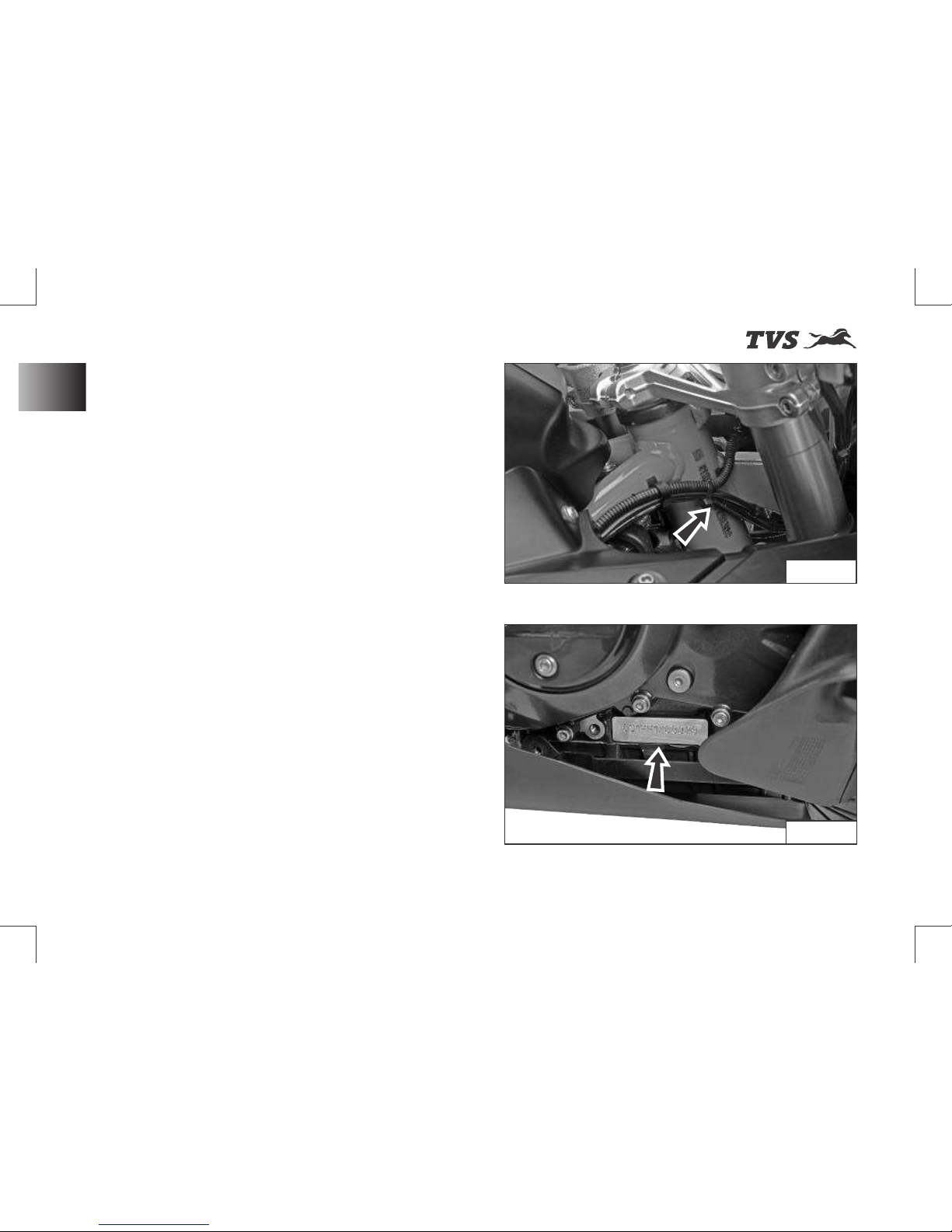
All TVS m otorc ycle s are p rovided w i t h
identification numbers for frame and engine.
They are the only means of identifying your
vehicle from others of the same model and type.
The frame identification number is engraved on
the right of the steering head tube as shown
(ref. Fig. 01).
----------------------------------------------------
----------------------------------------------------
The engine identification number is engraved
on th e r igh t side of e ngi n e a s s how n
(ref. Fig. 02).
----------------------------------------------------
----------------------------------------------------
KNOW YOUR MOTORCYCLE
Fig. 02
Fig. 01
12
Vehicle Identification Number
Page 27
st
Revision:- Rev. 1, 1 Aug'2018 onwards
Control Key
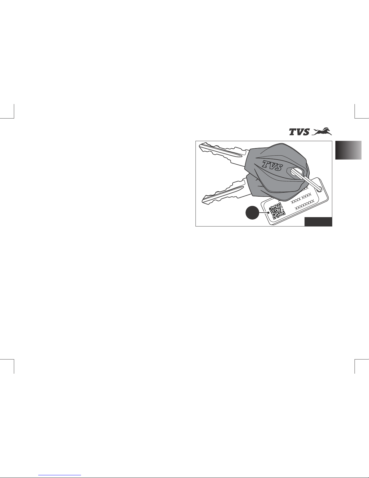
A pair of identical control keys are supplied with
your motorcycle. These keys are to operate
ignition cum steering lock, fuel tank cap and
seat lock.
A sticker ID (1) attached with keys has the
identification number of keys. Please note
down the identification number below for future
reference. (ref. Fig. 03)
----------------------------------------------------
Fig. 03
KNOW YOUR MOTORCYCLE
Control Key
1
13
Page 28
st
Revision:- Rev. 1, 1 Aug'2018 onwards
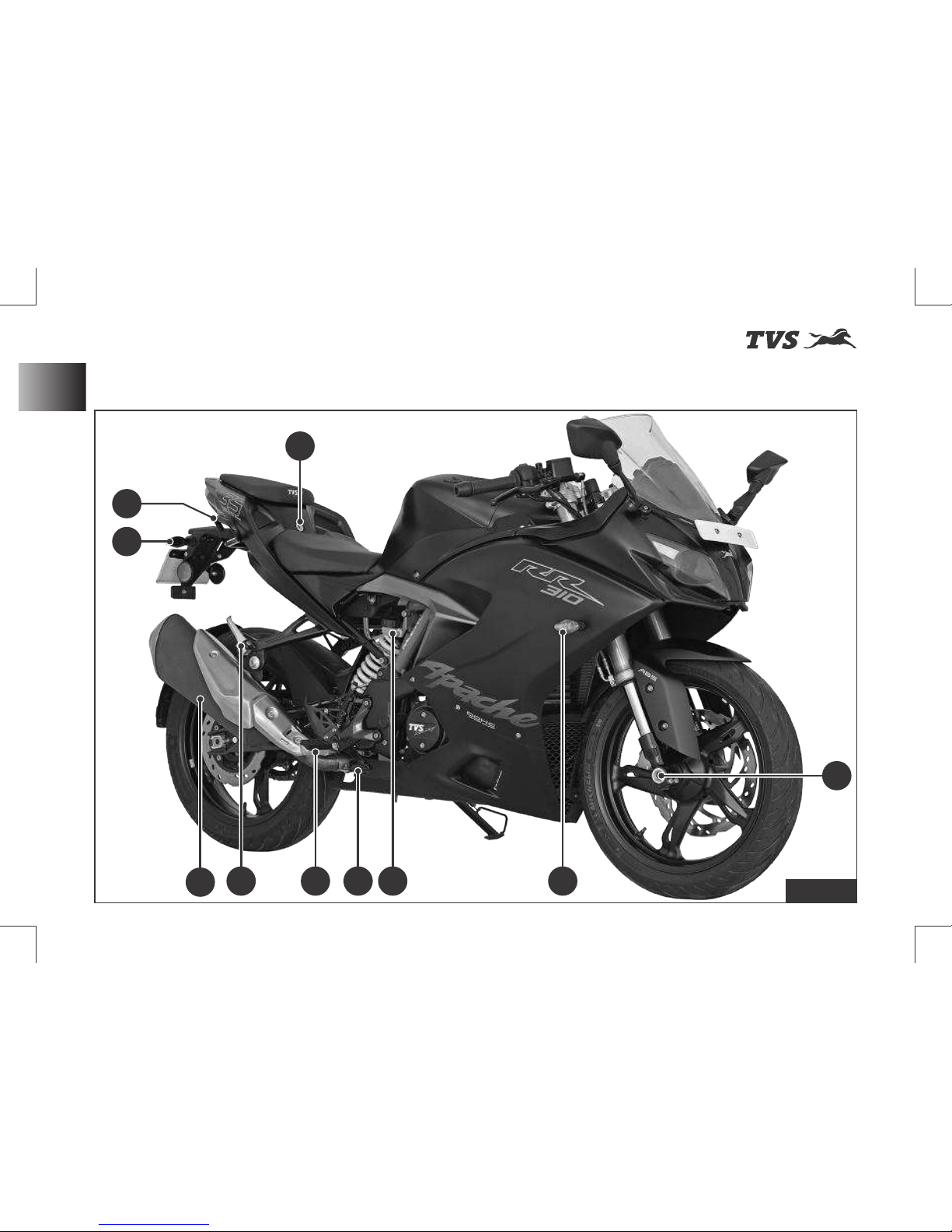
Location of Parts - Vehicle RH Side View
KNOW YOUR MOTORCYCLE
Fig. 04
14
Vehicle RH Side View
1
8
2
3
4
5
9
10
6
7
Page 29

st
Revision:- Rev. 1, 1 Aug'2018 onwards
Location of Parts - Vehicle RH Side View (Ref. Fig. 04)
KNOW YOUR MOTORCYCLE
1) Front wheel axle
2) Turn signal lamp RH front
3) 79) Reservoir, rear brake fluid (ref. page
4) Rear brake pedal (ref. page 44)
5) Rider foot rest RH
6) Pillion foot rest assembly RH
7) Muffler assembly
8) Turn signal lamp RH rear
9) Pillion handle
10) (ref. page 53) Seat lock
Vehicle RH Side View
15
Page 30
st
Revision:- Rev. 1, 1 Aug'2018 onwards
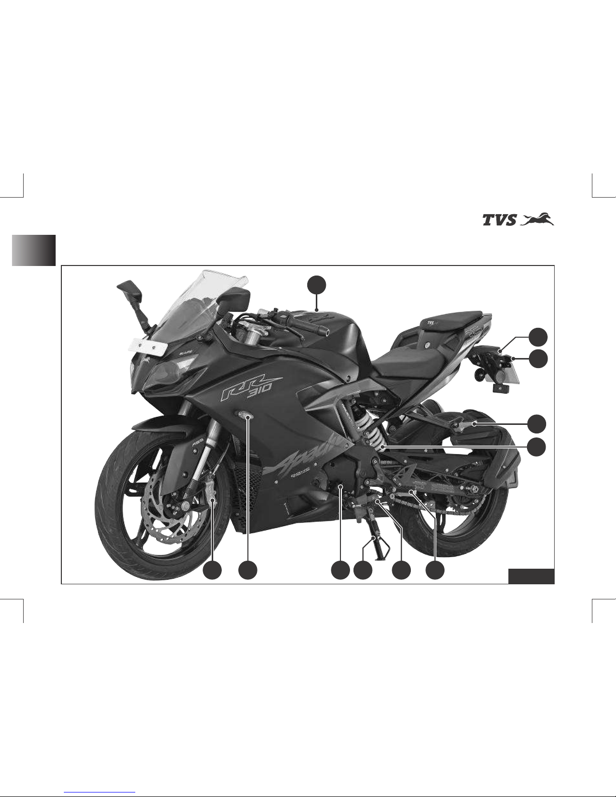
Location of Parts - Vehicle LH Side View
KNOW YOUR MOTORCYCLE
16
Vehicle LH Side View
Fig. 05
8
9
11
1 2
3
4
5
6
7
10
Page 31

st
Revision:- Rev. 1, 1 Aug'2018 onwards
Location of Parts - Vehicle LH Side View (Ref. Fig. 05)
KNOW YOUR MOTORCYCLE
1) Caliper assembly front
2) Turn signal lamp LH front
3) 74) Gauge oil level (dipstick) (ref. page
4) Side stand
5) Gear shift pedal 43) (ref. page
6) Rider foot rest LH
7) 52) Rear shock absorber (ref. page
8) Pillion foot rest assembly LH
9) Turn signal lamp LH rear
10) License plate lamp
11) Fuel tank cap assembly (ref. page 49)
Vehicle LH Side View
17
Page 32
st
Revision:- Rev. 1, 1 Aug'2018 onwards
Instrument Cluster
Instrument cluster will be activated once the
‘ignition lock’ is turned ON.
All segments and tell-tale indicators glow for
2 seconds on activation of instrument cluster for
checking and ensuring the proper working of
segments and indicators.
Following are the features of instrument cluster:
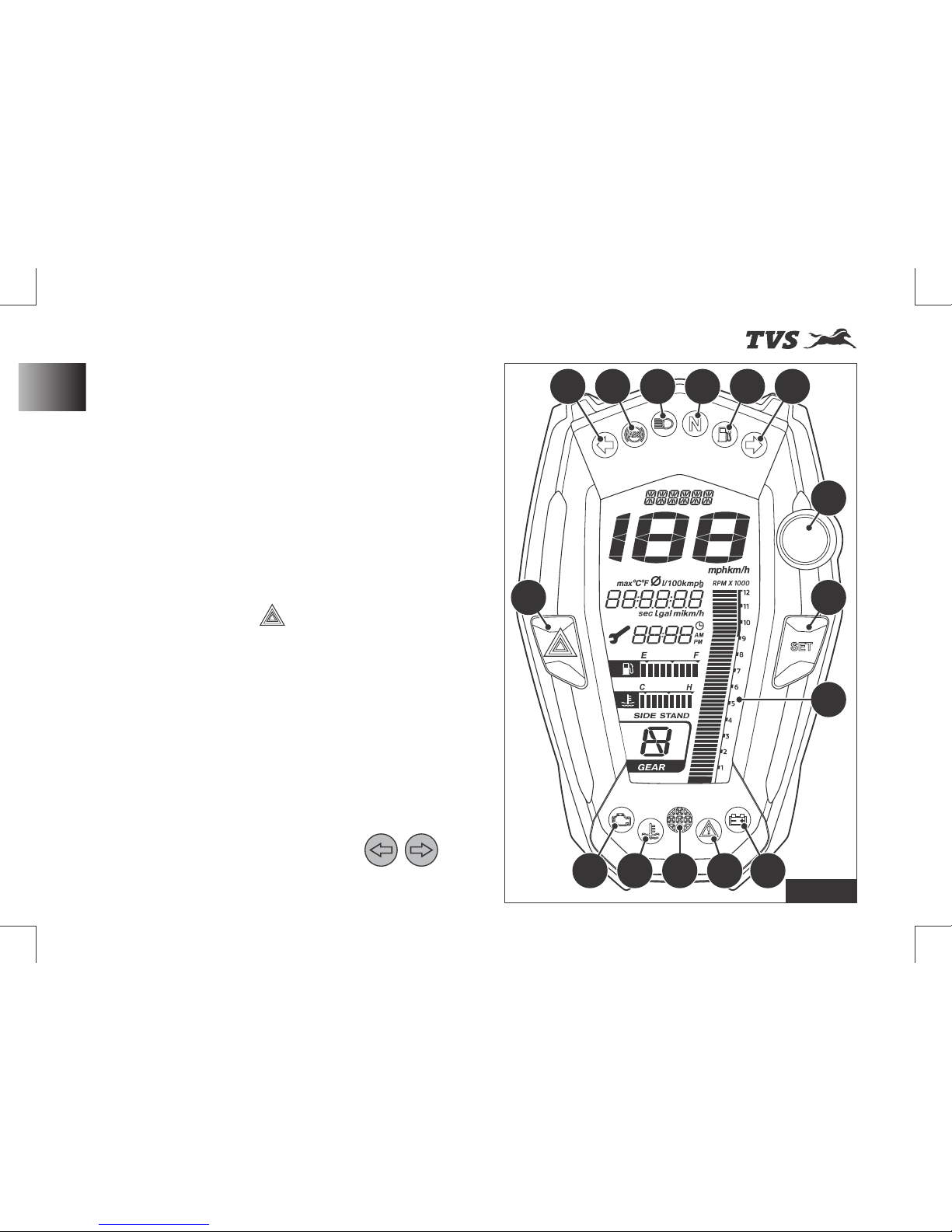
A) Hazard switch (ref. Fig. 06)
w Press the button ‘ ’ (A) to turn ON / OFF
the hazard lamps.
- If the hazard indication is turned ON while
the turn signal indicators are active, the turn
signal indic a to r s will be suspended
temporarily.
- Turn signal indication will resume
automatically once the hazard lamps are
turned OFF (if they were active before
hazard lamp ON).
- On activation of hazard lamps, both ‘left’
and ‘right’ turn signal indicators ‘ ’
flashes.
KNOW YOUR MOTORCYCLE
Instrument Cluster
Fig. 06
C1 C2 C3 C4 C5 C6
C7
B
D
C8C9C10C11C12
A
18
Page 33
st
Revision:- Rev. 1, 1 Aug'2018 onwards
KNOW YOUR MOTORCYCLE
B) SET button (ref. Fig. 06)
w Press the button (B) for selecting the display
mode.
- Press (short press) the button repeatedly
till the desired menu is displayed.
Ex. ODO, Range, IMI, Mileage etc.
- Press (long press) the button to store the
values or to reset the stored values.
Note
Hazard lamps can be switched
ON/OFF only by means of hazard switch.
Hazard switch works only when the ignition is
turned ON and the lamps continue to work
even if the ignition is turned OFF during its
working.
Avoid using hazard lamps while the engine is
turned OFF for prolonging time to avoid
battery drain.
C) Warning and indicator lights (ref. Fig. 06)
C1) Turn signal indicator LH
C2) ABS indicator
C3) High beam indicator
C4) Neutral indicator
C5) Fuel warning indicator
C6) Turn signal indicator RH
C7) Gear shift indicator / over speed
warning
C8) Low battery indicator
C9) General warning indicator
C10) Photo sensor
C11) Engine temperature indicator
C12) Malfunction indicator
Warning
Display setting to be done
only when the motorcycle is stationary. Never
operate the instrument panel controls while
riding the motorcycle for safety.
19
Instrument Cluster
Page 34
st
Revision:- Rev. 1, 1 Aug'2018 onwards
KNOW YOUR MOTORCYCLE
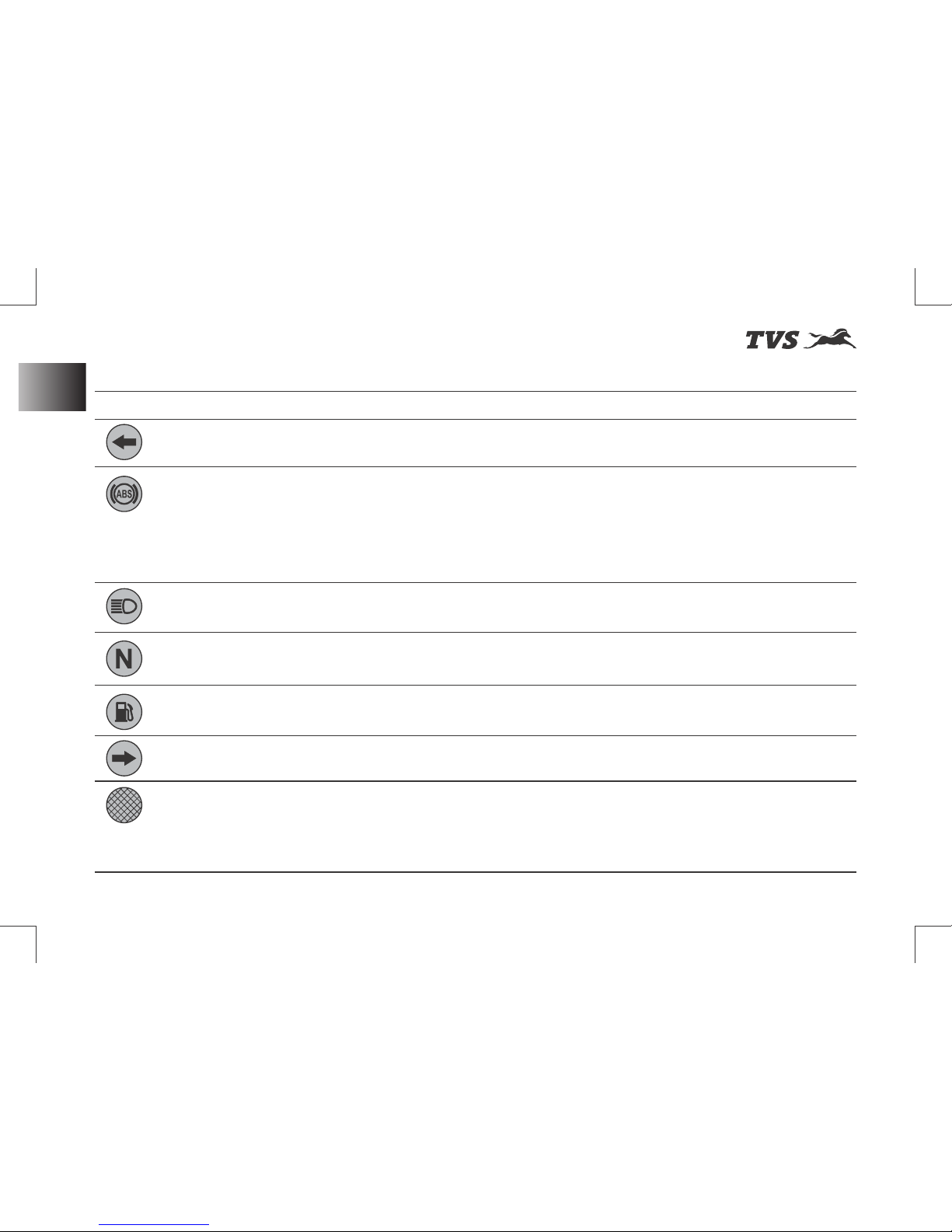
Warning and indicator lights (ref. Fig. 06)
LSymbol ights Meaning
C1. Turn signal indicator LH Flashes when the left side turn signal indication is activated
C2. ABS indicator Flashes when the ABS self-diagnostic not completed / not
yet initiated - Ride the vehicle few kms.
Glows continuously when the ABS has an error or
malfunction*
Goes OFF after few kms run - ABS is active and ready to use
3. High beam indicatorC Glows when the head lamp high beam is activated
C4. Neutral indicator Glows when the vehicle is in neutral condition
C5. Fuel warning indicator Glows when the fuel level in the tank reaches to minimum
safe level or any mal function in the fuel level sensor*
C6. Turn signal indicator RH Flashes when the right side turn signal indication is activated
C7. Gear shift indicator Glows when the rpm reaches high on the selected gear,
which will in-turn consumes more fuel - shift to next gear. It is
not enabled for neutral and 6th gear. It also works as a speed
limit indicator (if the limit is set by the user ref. page 28).
* Contact TVS Motor Company Limited Authorised Main Dealer
20
Instrument Cluster
Page 35
st
Revision:- Rev. 1, 1 Aug'2018 onwards
* Contact TVS Motor Company Limited Authorised Main Dealer
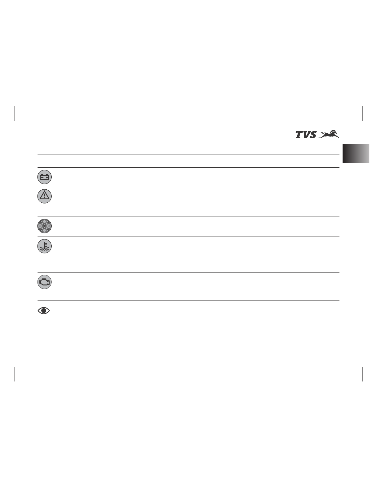
Warning and indicator lights
KNOW YOUR MOTORCYCLE
Symbol Lights Meaning
C8. Low battery indicator Glows when the battery voltage is low*
C9. General warning indicator Glows when a warning is active and for which no separate
warning indicators are provided.
Example: Side stand ON.
C10. Photo sensor Adjusts the LCD brightness and tell tale indicators
brightness automatically as per day and night conditions.
C11. Engine temperature Flashes when the coolant temperature is very high or if any
malfunction in the coolant temperature sensor (stop the
engine to avoid serious damage if this indicator is
flashing).*
C12. Malfunction indicator Glows when any problem is detected in engine
management system causing vehicle to exceed on-board
diagnostic emission threshold.*
Note
The instrument cluster monitors the battery voltage and if the voltage persists less
than 11.5 volts for a period of 5 seconds, the cluster switches OFF itself.
The vehicle automatically goes to reduced performance mode if the engine temperature is very
high.
21
Instrument Cluster
Page 36
st
Revision:- Rev. 1, 1 Aug'2018 onwards
KNOW YOUR MOTORCYCLE
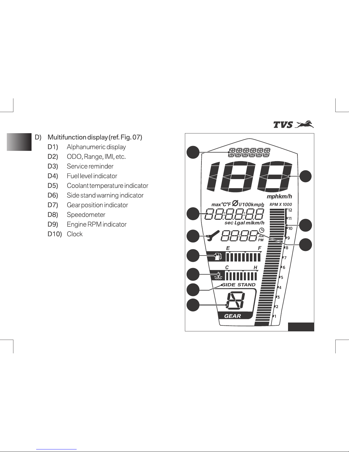
Instrument Cluster
Fig. 07
D1
D2
D3
D4
D5
D6
D7
D8
D9
D10
22
Page 37
st
Revision:- Rev. 1, 1 Aug'2018 onwards
KNOW YOUR MOTORCYCLE
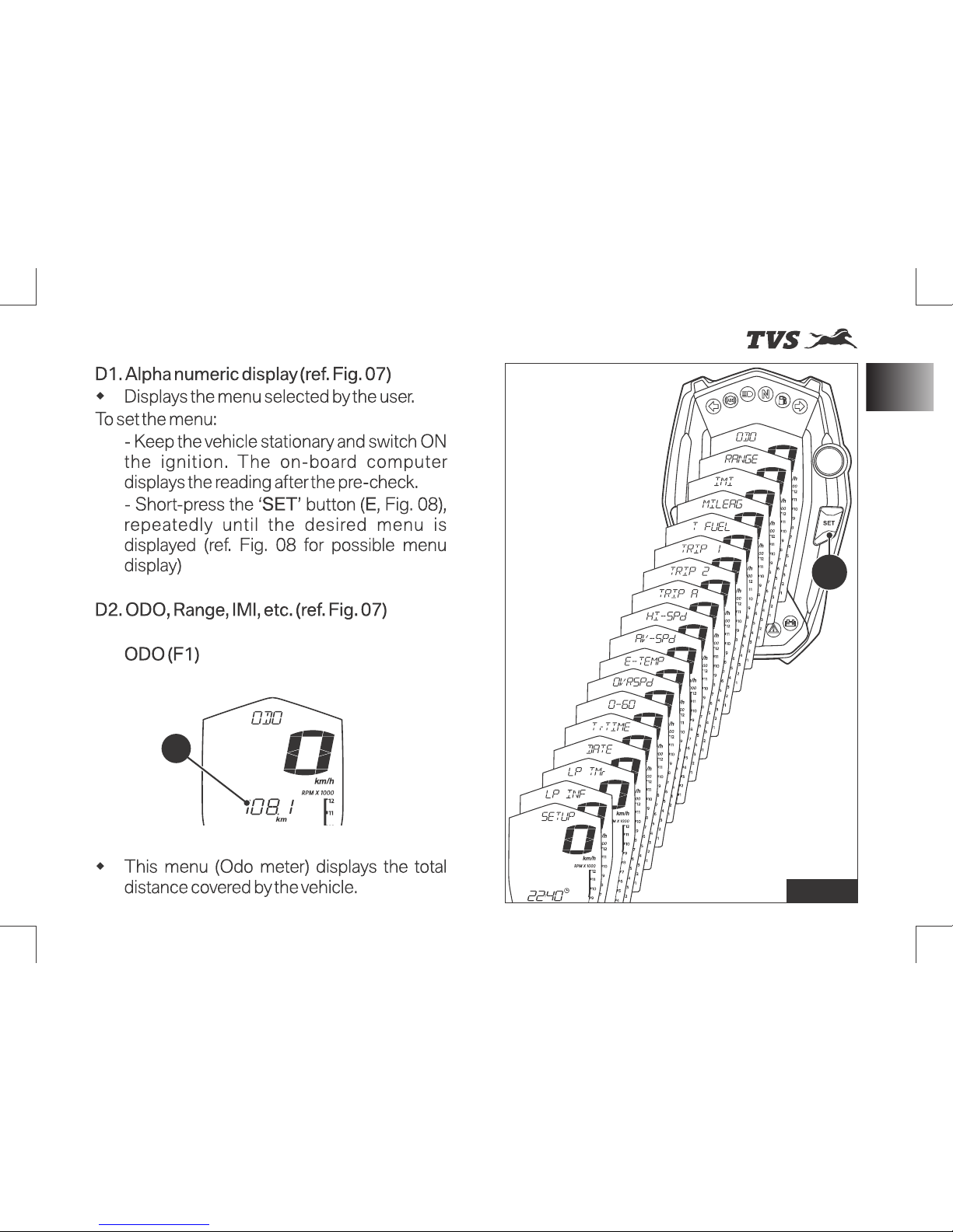
Fig. 08
F1
E
23
Instrument Cluster
Page 38
st
Revision:- Rev. 1, 1 Aug'2018 onwards
KNOW YOUR MOTORCYCLE
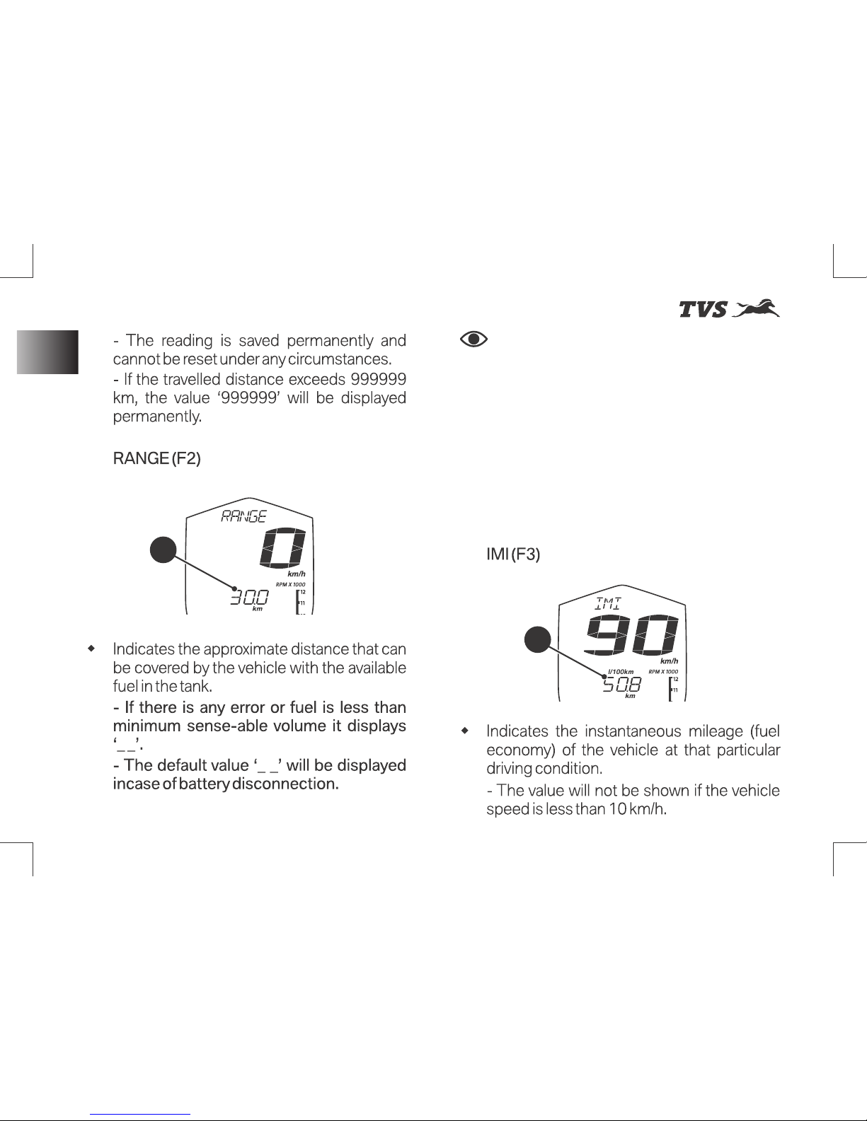
Note
If the fuel in the tank reaches to
minimum safe level, the display switches over
to ‘Range’ mode automatically instead of any
other mode set by the user.
The ‘Range’ reading may not be accurate
when the vehicles is propped on side stand
and should be calculated only when the side
stand is folded.
Instrument Cluster
F2
F3
24
Page 39
st
Revision:- Rev. 1, 1 Aug'2018 onwards
KNOW YOUR MOTORCYCLE
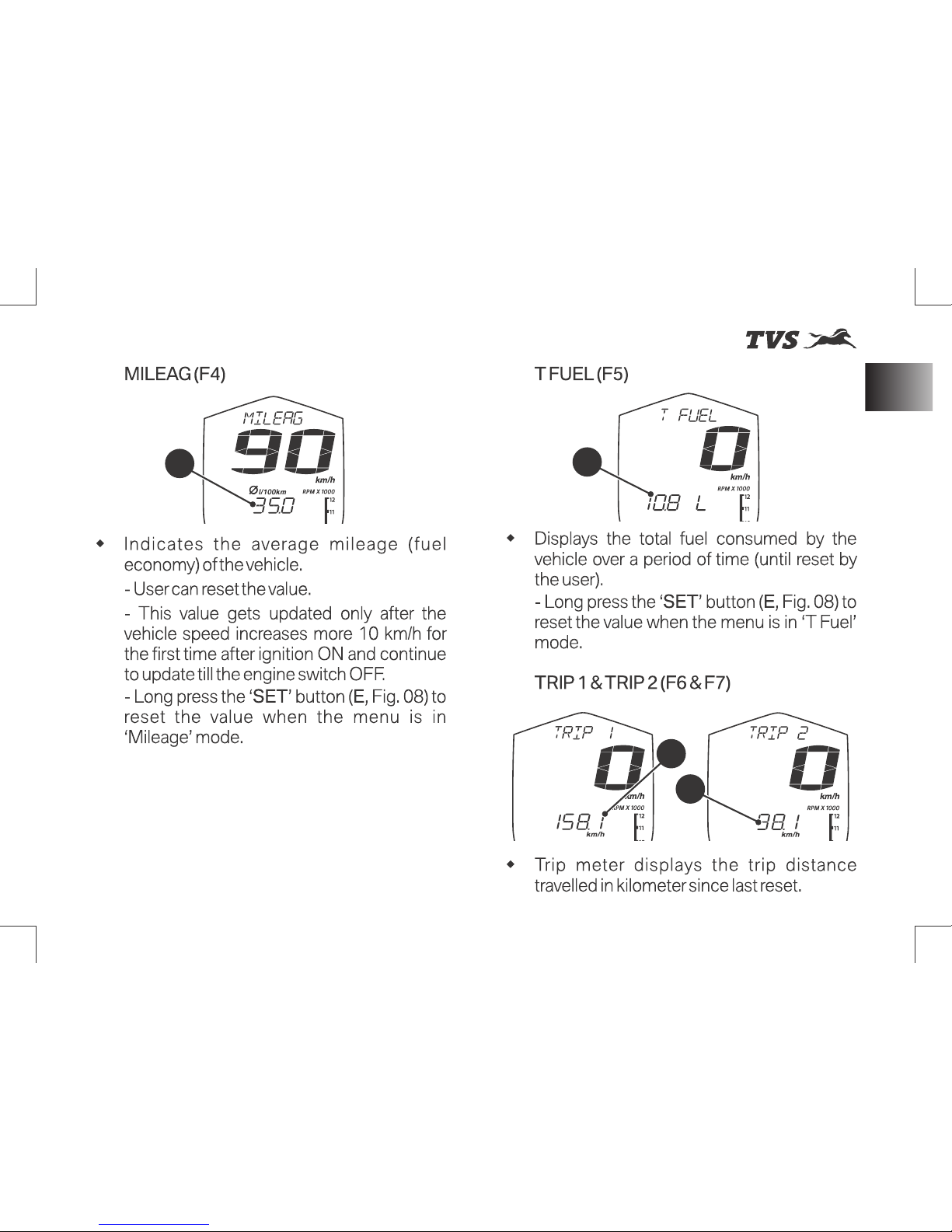
F5
F4
F7
F6
25
Instrument Cluster
Page 40
st
Revision:- Rev. 1, 1 Aug'2018 onwards
KNOW YOUR MOTORCYCLE
Instrument Cluster
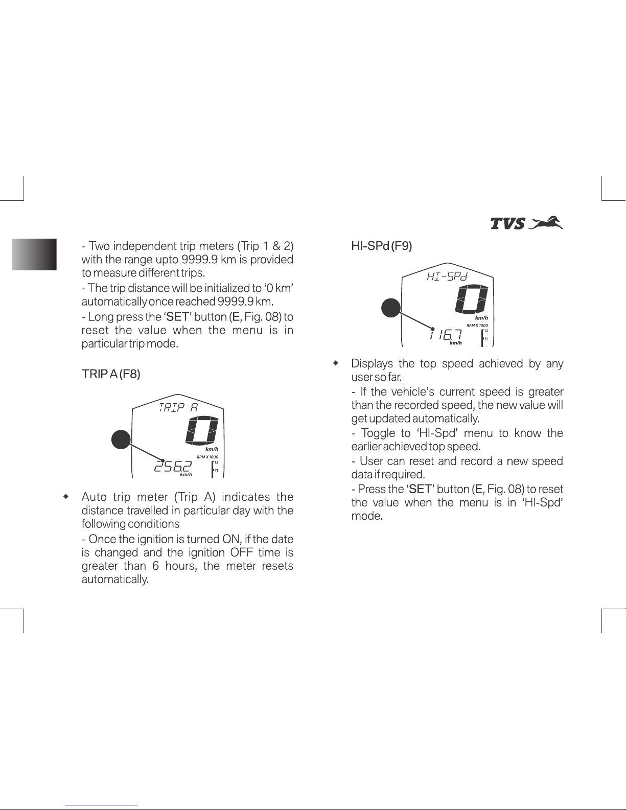
F8
F9
26
Page 41
st
Revision:- Rev. 1, 1 Aug'2018 onwards
KNOW YOUR MOTORCYCLE
Caution
Stop riding the vehicle if the
temperature reaches to maximum limit, else it
might result in engine damage.
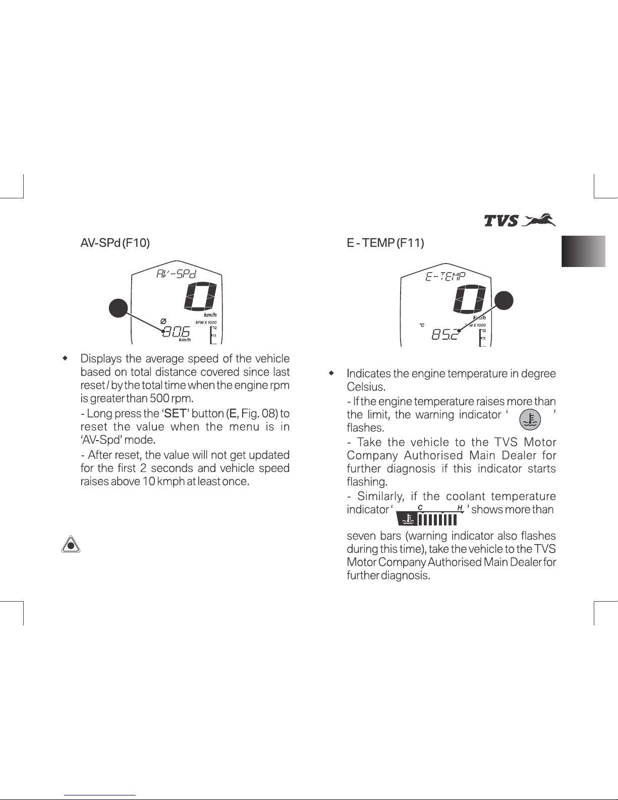
F10
F11
Instrument Cluster
27
Page 42
st
Revision:- Rev. 1, 1 Aug'2018 onwards
KNOW YOUR MOTORCYCLE
Instrument Cluster
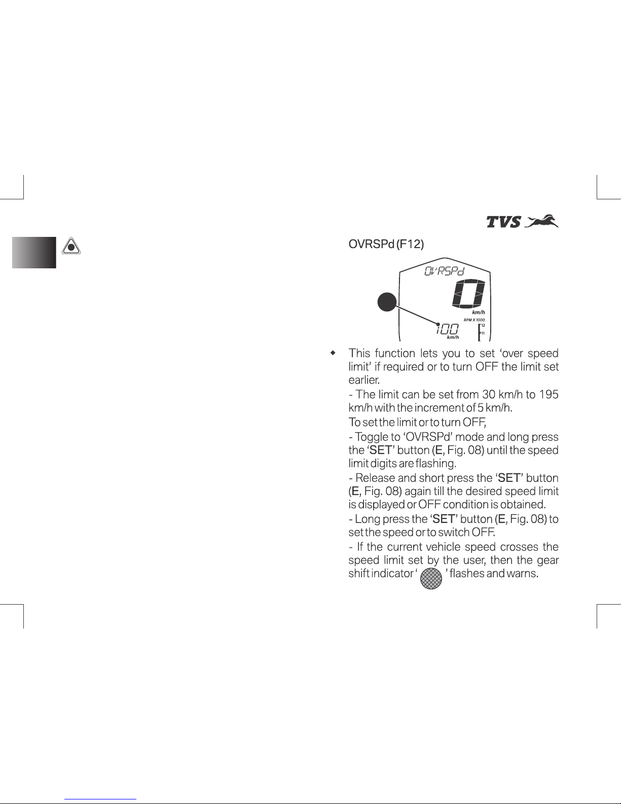
F12
Caution
I n c a s e o f c o o l a n t
temperature sensor fault or cooling fan fault
or throttle position sensor fault, the vehicle
will go to reduced performance mode (limphome) in order to safe guard the bike from any
damage and also to protect the rider.
The high temperature tell-tale will be ON also
in the case of coolant temperature sensor
error, in addition to high temperature warning
functionality (the digital value displayed in the
cluster will be last recorded correct value of
the vehicle’s ECU).
28
Page 43
st
Revision:- Rev. 1, 1 Aug'2018 onwards
KNOW YOUR MOTORCYCLE
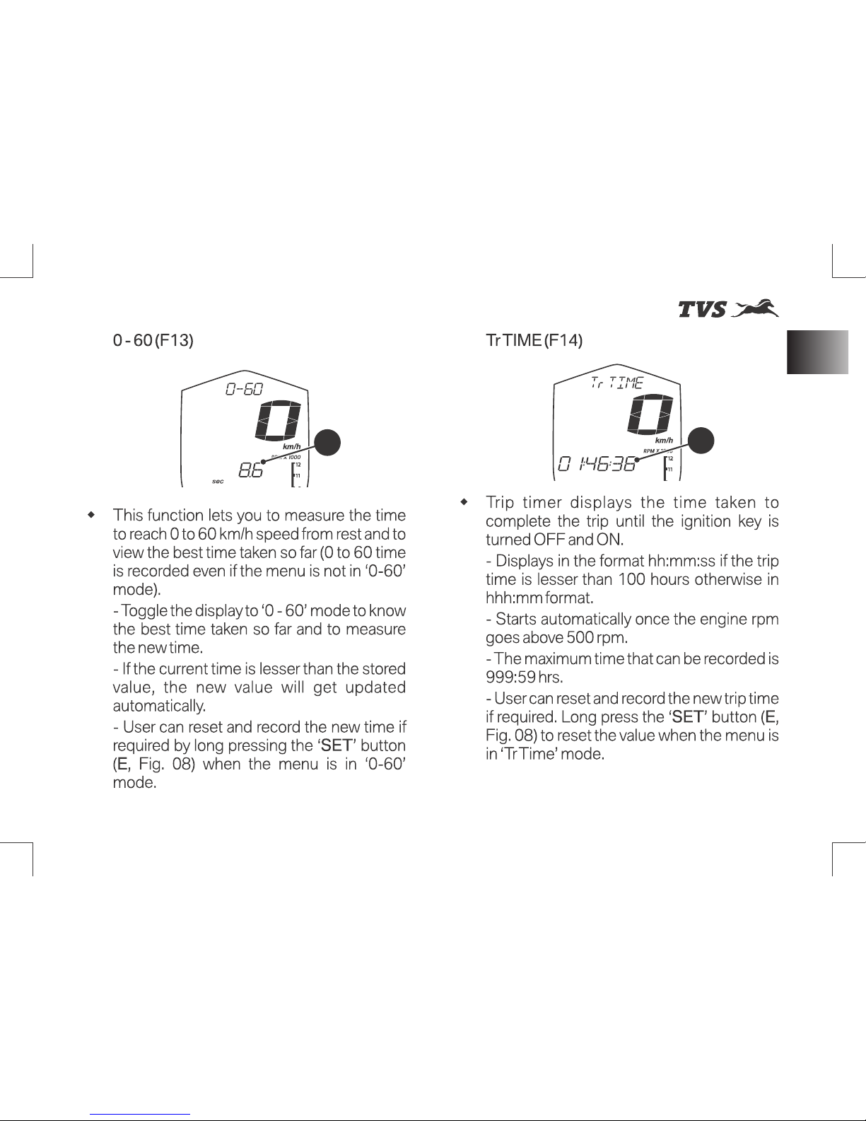
F14
F13
29
Instrument Cluster
Page 44
st
Revision:- Rev. 1, 1 Aug'2018 onwards
KNOW YOUR MOTORCYCLE
Instrument Cluster
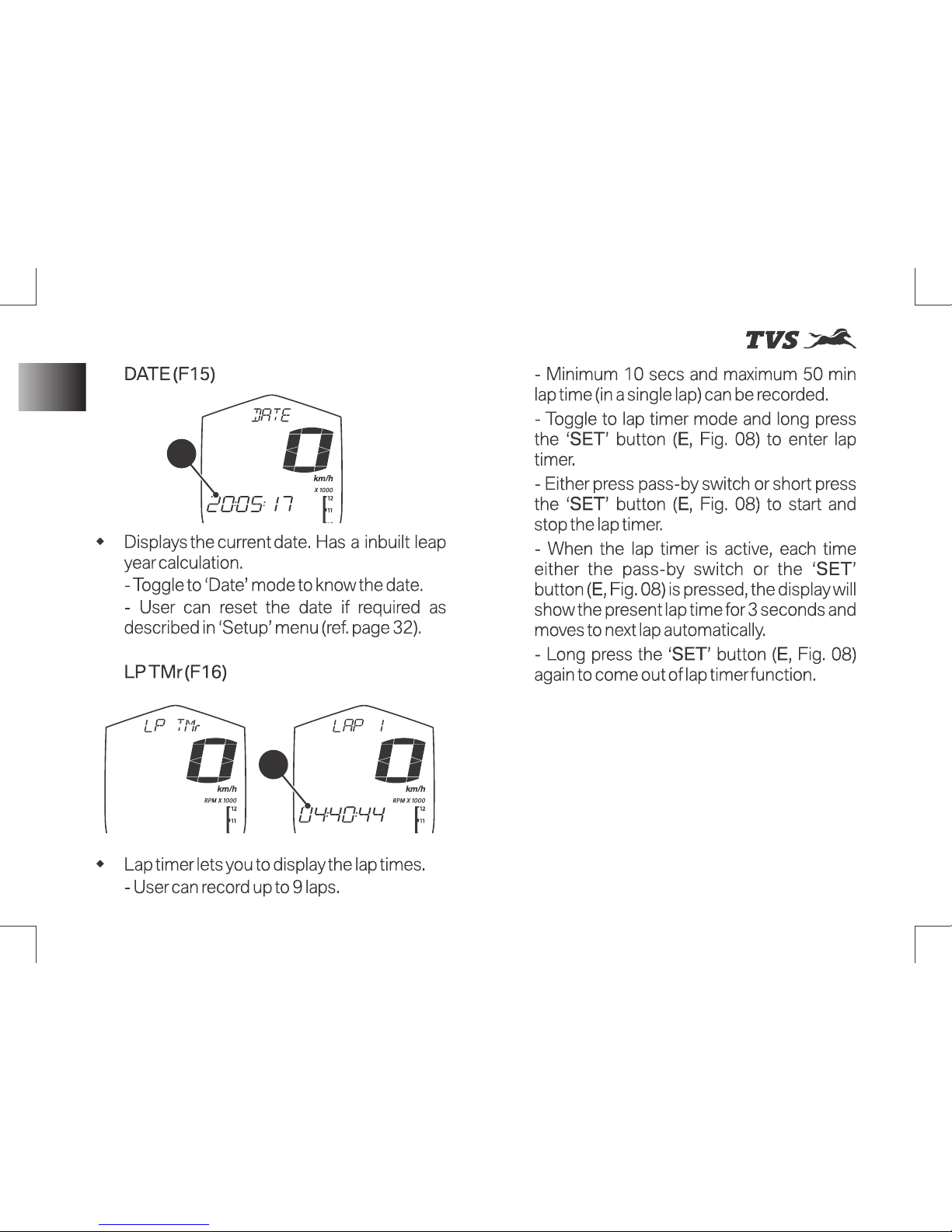
F15
F16
30
Page 45
st
Revision:- Rev. 1, 1 Aug'2018 onwards
KNOW YOUR MOTORCYCLE
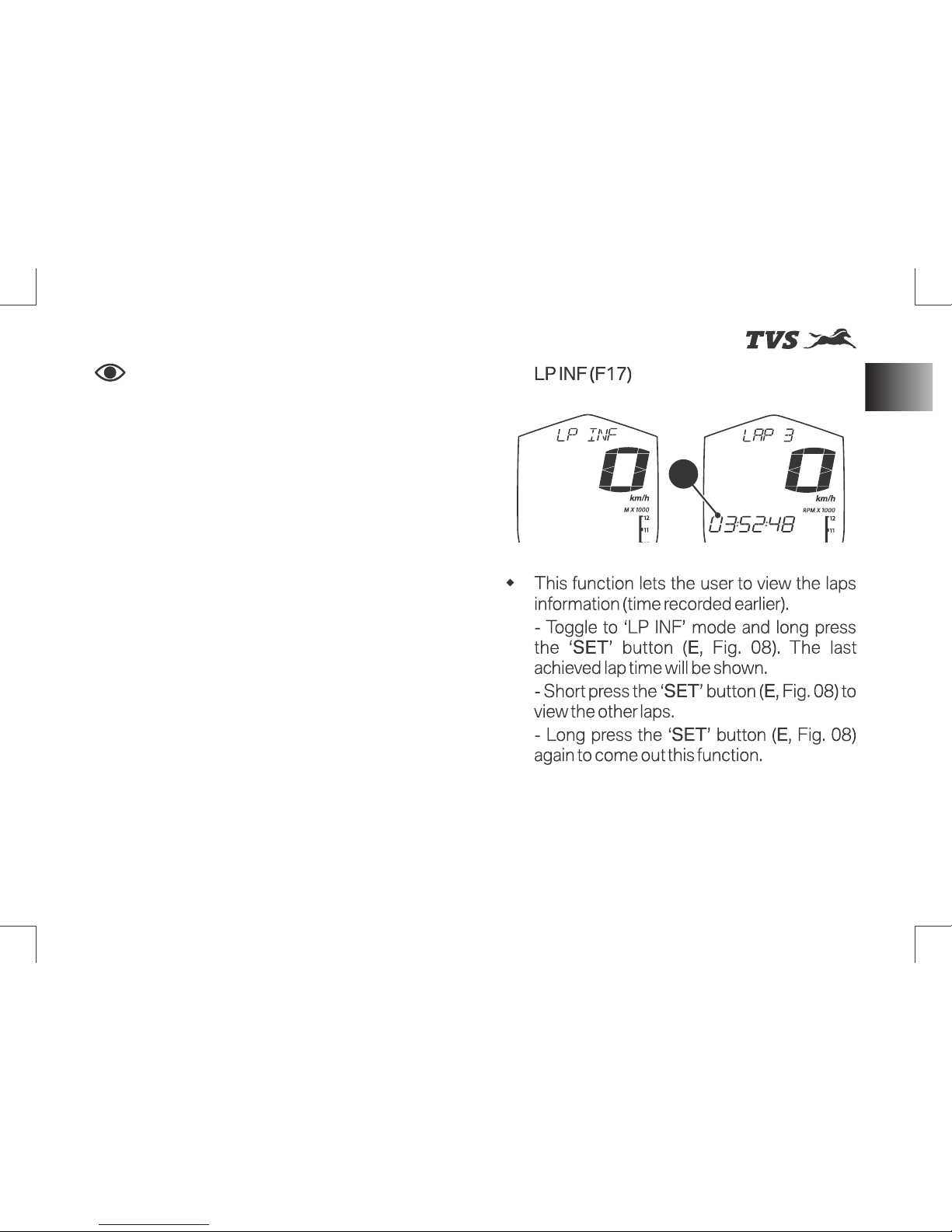
F17
Note
If the lap timer is continued even
after completing 9 laps, the control moves to
first lap automatically (first lap starts again)
and will keep running until the function is
disabled. The earlier recorded values will be
overridden automatically.
If a particular lap time reaches 50 minutes, the
next l ap st arts au t omat ical ly wi thou t
activating any switch.
The ‘lap’ function is disabled automatically if
the ‘ignition lock’ or ‘switch engine cut off’ is
turned OFF while it is active and the current
lap time will not get stored even though the
lap timer had been active before the turning
OFF the ‘lock / switch’.
If the lap timer function is switched ON when
only fewer laps have been completed earlier
(eg. 4 laps completed), it starts from the next
lap only (5th lap) and not from the first.
Lap times can’t be reset and it will be
overridden automatically when the lap is
active next time.
31
Instrument Cluster
Page 46
st
Revision:- Rev. 1, 1 Aug'2018 onwards
KNOW YOUR MOTORCYCLE
Instrument Cluster
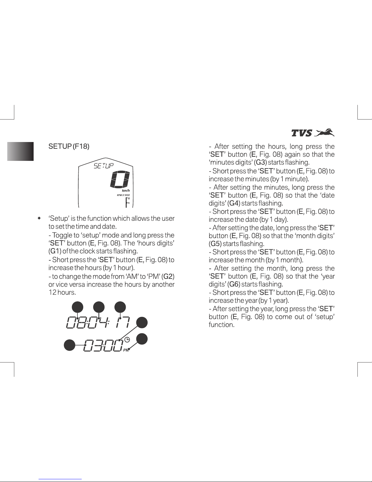
G4 G5 G6
G3
G2
G1
32
Page 47
st
Revision:- Rev. 1, 1 Aug'2018 onwards
KNOW YOUR MOTORCYCLE
Note
During clock setting, if there is a
delay in input (more than 3 seconds) the
system will come out of the setting procedure
automatically.
Wh e ne ve r t h e in s t ru m en t cl us te r is
disconnected from the battery supply, the
time and the date set earlier will get reset and
need to be set again.
33
Instrument Cluster
Page 48
st
Revision:- Rev. 1, 1 Aug'2018 onwards
KNOW YOUR MOTORCYCLE
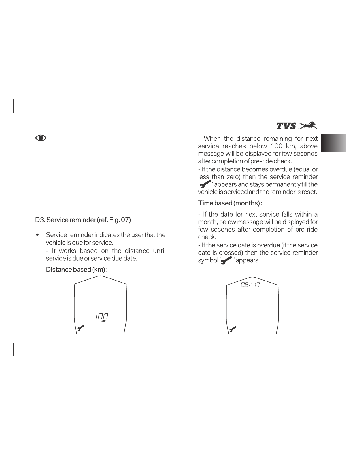
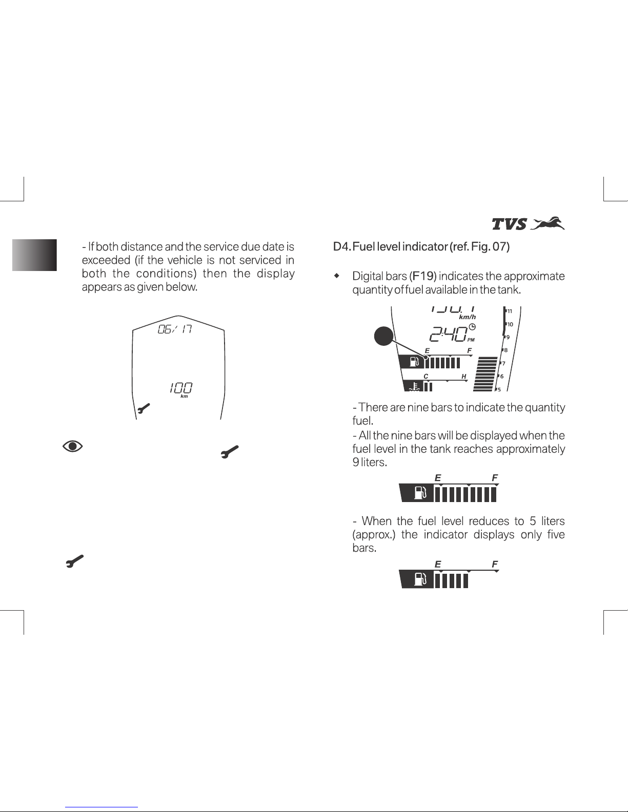
F19
Note
Service reminder ‘ ’ appeared
will stays ON until it is reset at TVS Motor
Company Authorised Main Dealer as a part of
service procedure.
Service reminder date set earlier gets erased
incase of battery disconnection or by any
other mode. The service indication symbol
‘ ’ will be displayed permanently until the
service date is fed again and the reminder is
reset.
34
Instrument Cluster
Page 49
st
Revision:- Rev. 1, 1 Aug'2018 onwards
KNOW YOUR MOTORCYCLE
Warning
Caution
Do not run the fuel tank dry
to avoid failure of fuel pump and other
consequential damages if any.
If the vehicle is run with very
less fuel it will result in improper engine
operation or shutdown due to lack of fuel
which may result in accident.
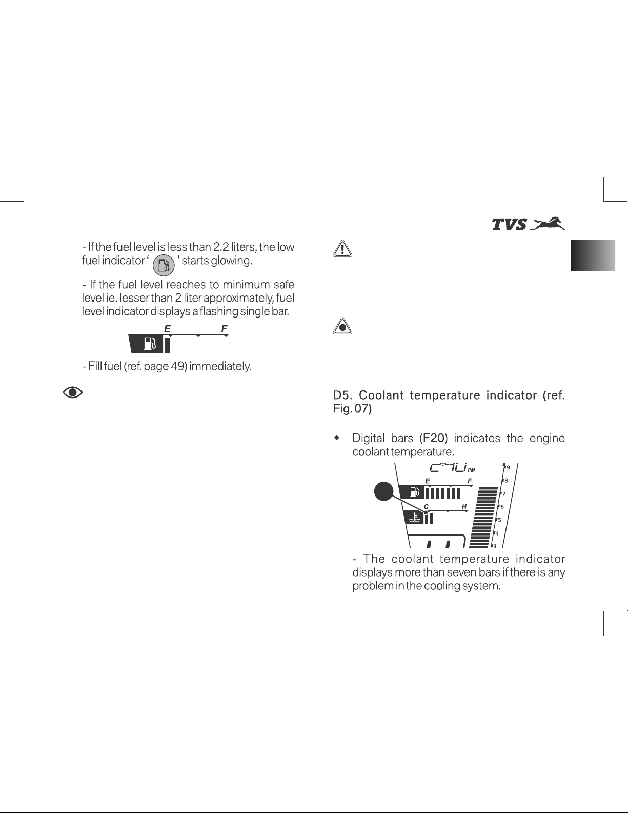
F20
Note
I f th e fu e l l evel re ach es t o
minimum safe level, the display switches over
to ‘Range’ mode automatically.
Please ensure that the fuel bar indication in
cluster is greater than 1 bar always. It is
dangerous to ride with 1 bar or less.
Incase of any error in input system, all the bars
of fuel level indicator flashes and fuel warning
indicator turns ON. In addition to that, reading
‘_ _ ’ will be displayed in the ‘Range’ mode.
Contact nearest TVS Motor Company
Authorised Main Dealer incase any of these
problems are noticed.
35
Instrument Cluster
Page 50
st
Revision:- Rev. 1, 1 Aug'2018 onwards
KNOW YOUR MOTORCYCLE
Note
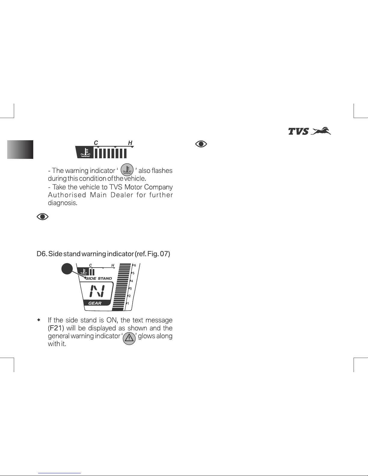
The vehicle will start in side stand
in neutral gear but it will not in other gears.
The vehicle will also ‘switch off’ if the side
stand is ON and gear is changed from neutral
to gear.
Incase of any errors in side stand switch - side
stand indication will be always ON in the
instrument cluster immaterial of side stand
status.
In the event of any unfortunate accident, if the
side stand / side stand switch has been
damaged, the signal can be bypassed by
disconnecting the side stand switch coupler.
F21
Note
The vehicle automatically goes
to reduced performance mode if the engine
temperature is very high.
36
Instrument Cluster
Page 51
st
Revision:- Rev. 1, 1 Aug'2018 onwards
KNOW YOUR MOTORCYCLE
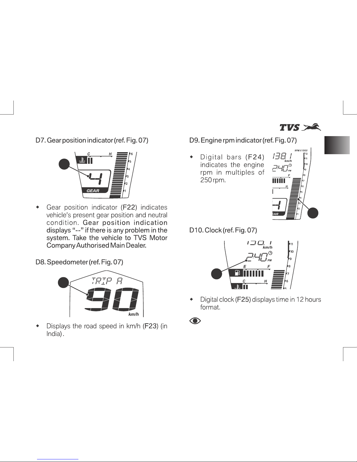
F24
F25
Note
Reset the clock timing incase of
battery disconnection (ref. page 32).
F22
F23
37
Instrument Cluster
Page 52
st
Revision:- Rev. 1, 1 Aug'2018 onwards
KNOW YOUR MOTORCYCLE
Warning
This s ection shows the
position and function of the controls used to
ride your motorcycle. Read this section
carefully before riding the motorcycle.
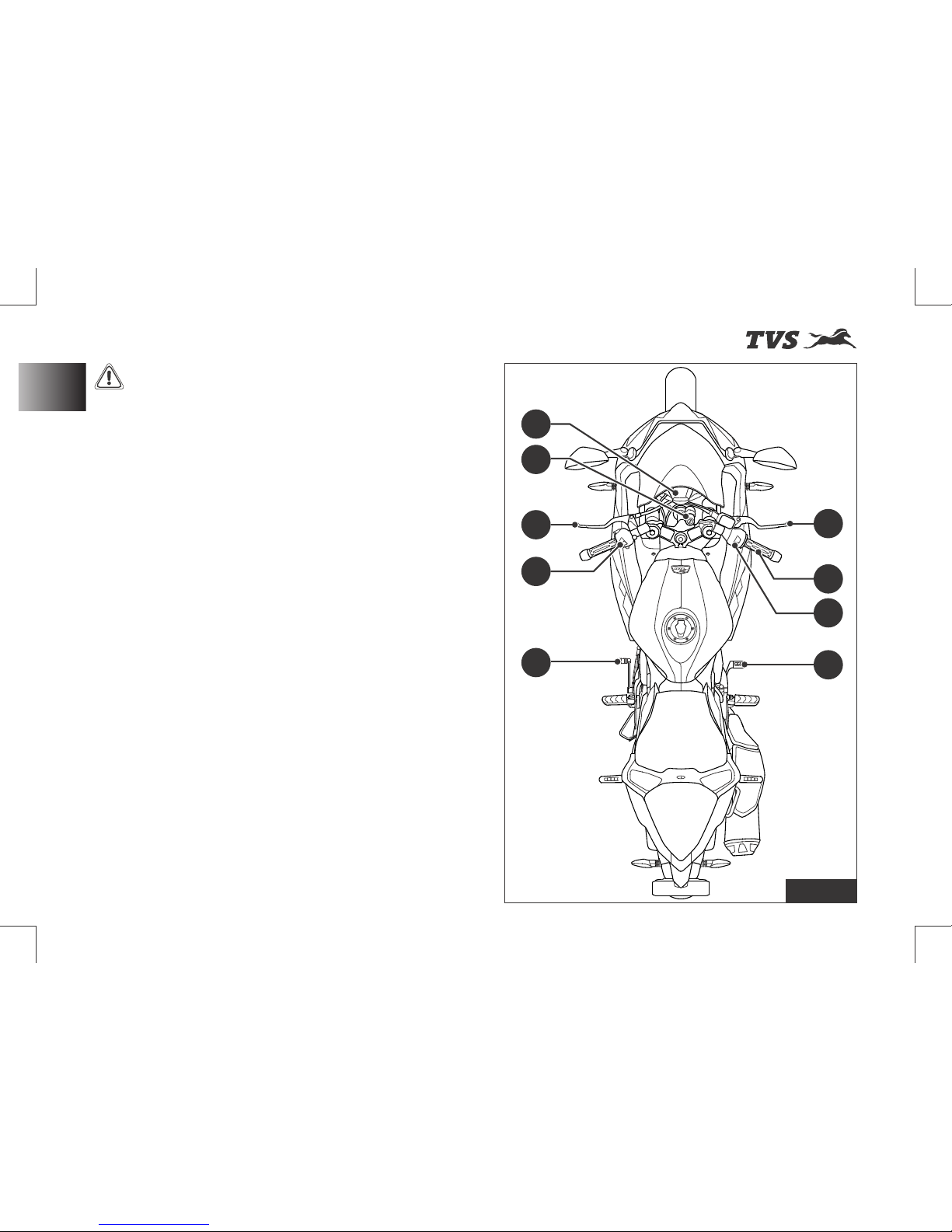
Controls (ref. Fig. 9)
1) Instrument cluster (ref. page 18)
2) Ignition cum steering lock (ref. page 39)
3) Clutch lever (ref. page 40)
4) Switch assembly LH (ref. page 41)
5) Gear shift pedal (ref. page 43)
6) Rear brake pedal (ref. page 44)
7) Switch assembly RH (ref. page 44)
8) Throttle twist grip (ref. page 46)
9) Front brake lever (ref. page 46)
Fig. 9
2
4
5
6
7
8
9
1
3
Controls & Its Operations
38
Page 53
st
Revision:- Rev. 1, 1 Aug'2018 onwards
KNOW YOUR MOTORCYCLE
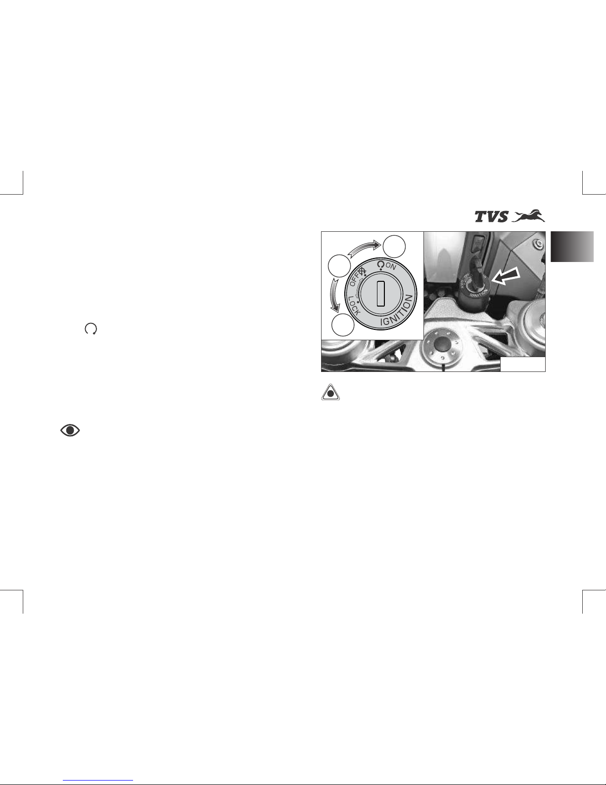
Ignition cum Steering Lock
Ignition cum steering lock is located in front of
fuel tank and has three positions (ref. Fig. 10) :
w OFF (A): Disables lights and engine
operation.
w ON (B): Enables lights and engine operation
(with engine cut off switch is in run mode
‘ ’).
w LOCK (C): Steering is locked
- To lock the steering, turn the handle bar all
the way towards ‘left’ or ‘right’, push the key
in and turn it to LOCK position.
- Push and turn the key to OFF or ON
position to unlock.
Note
Control key can’t be taken out
from the lock at position (B).
The head lamp, tail lamp and license plate
lamp will glow automatically when the
ignition is turned ON without operating any
other switches.
The instrument cluster performs pre-check
once the ‘ignition lock’ is turned ON. Wait till
the completion of pre-check.
Caution
On level ground, always turn
the handle bar towards left while locking the
steering when the vehicle is propped with
side stand. Else the vehicle may fall and may
get damaged. Otherwise the angle of the
ground determines the steering position
(‘left’ or ‘right’).
Always lock the steering while parking for
safety.
Ensure that, you do not keep the ignition ‘ON’
without starting the engine for a long time as
battery might get drained because of AHO.
H
S
U
P
B
A
C
Fig. 10
39
Controls & Its Operations
Page 54
st
Revision:- Rev. 1, 1 Aug'2018 onwards
KNOW YOUR MOTORCYCLE
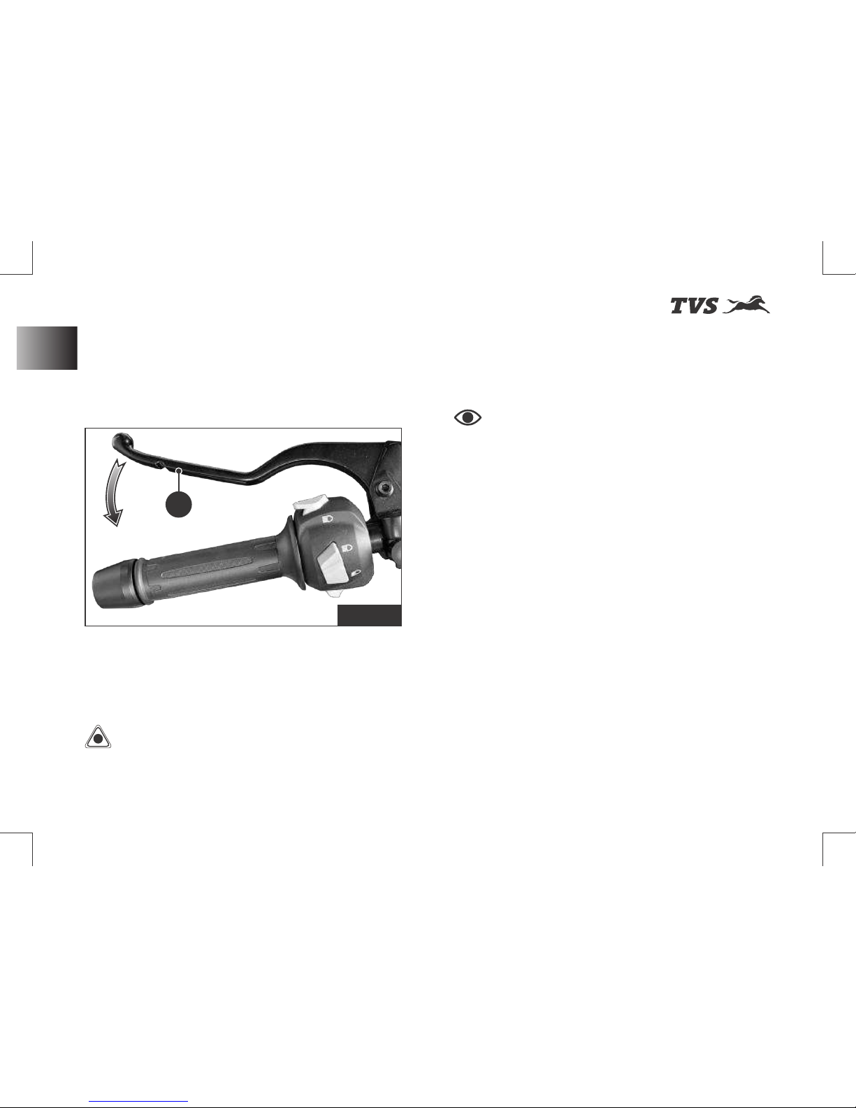
Clutch Lever (ref. Fig. 11)
Clutch lever (A) is located in the handle bar at LH
side.
w Clutch lever is used to disengage clutch.
- When the clutch is pressed, drive from the
engine to the gearbox and the rear wheel is
disengaged.
Caution
Prop er usag e o f c lut ch
increases the life of engine component and
prevent any damage to the transmission
components of engine.
Note
Apply the clutch when starting
the vehicle with gear engaged.
Increase in engine rpm during acceleration,
without increase in road speed indicates the
clutch slip. A slipping clutch causes high fuel
consumption and engine overheating. Refer
page 76 for clutch adjustment procedure.
- Proper use of clutch lever is essential in all
riding situations, especially while moving
the vehicle from rest.
Fig. 11
40
Controls & Its Operations
A
Page 55
st
Revision:- Rev. 1, 1 Aug'2018 onwards
KNOW YOUR MOTORCYCLE
Switch Assembly LH
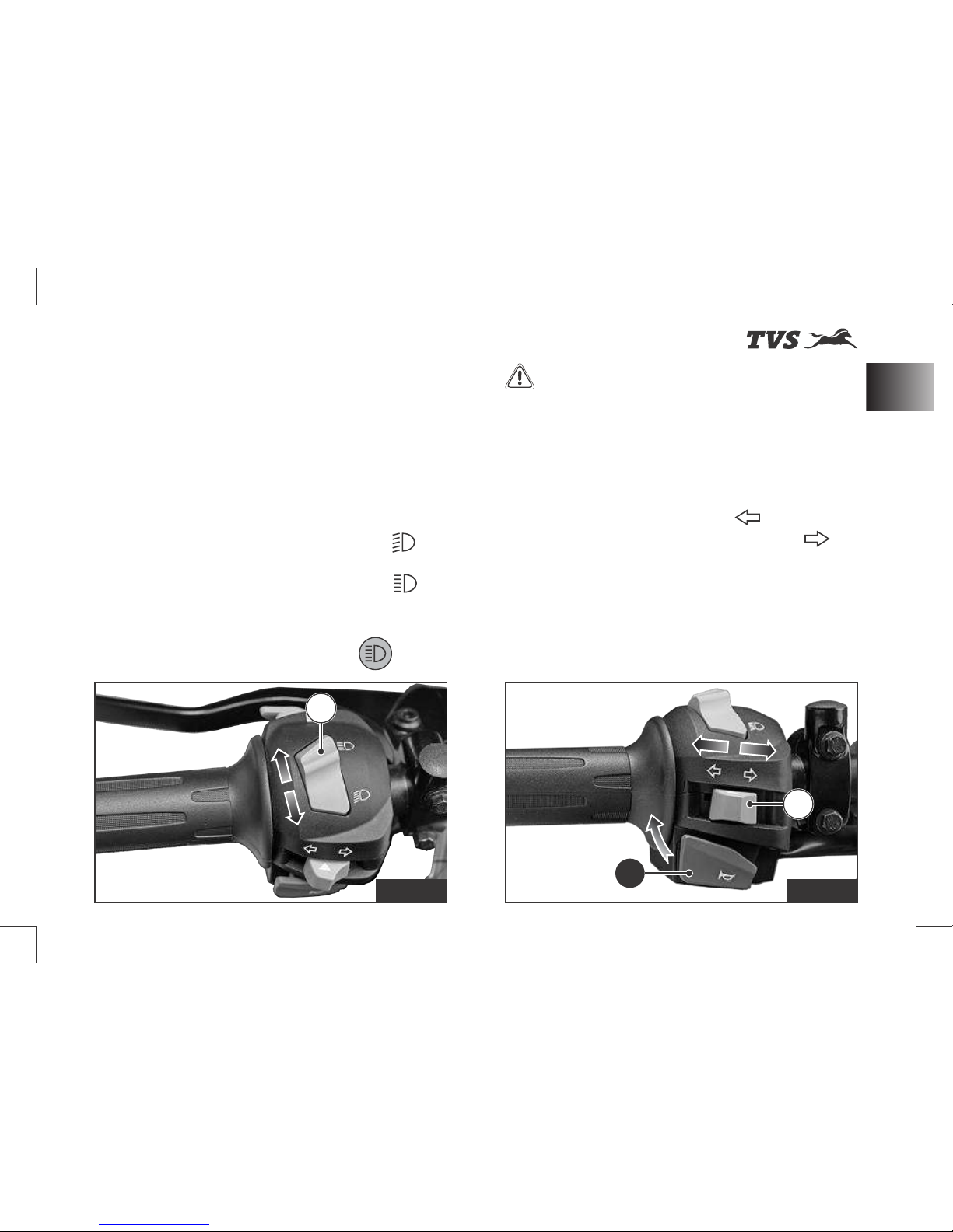
Switch assembly LH is located in the handle bar
at LH side and has the following switches in it.
A) Switch beam control (ref. Fig. 12)
Head lamp glows automatically when the
ignition turned ON. Depending on the selection
of High/Low beam switch position, head lamp
will operate in corresponding beam.
w Press the switch towards you ‘ ’ to
illuminate low beam
w Press the switch away from you ‘ ’ to
illuminate high beam.
- When the head lamp is illuminated in high
beam, the high beam indicator ‘ ’ glows
along with it.
Warning
Use appropriate head lamp
beam 'high / low' as per the traffic and road
con di t io ns f o r you r sa fet y an d avo id
inconvenience to other riders.
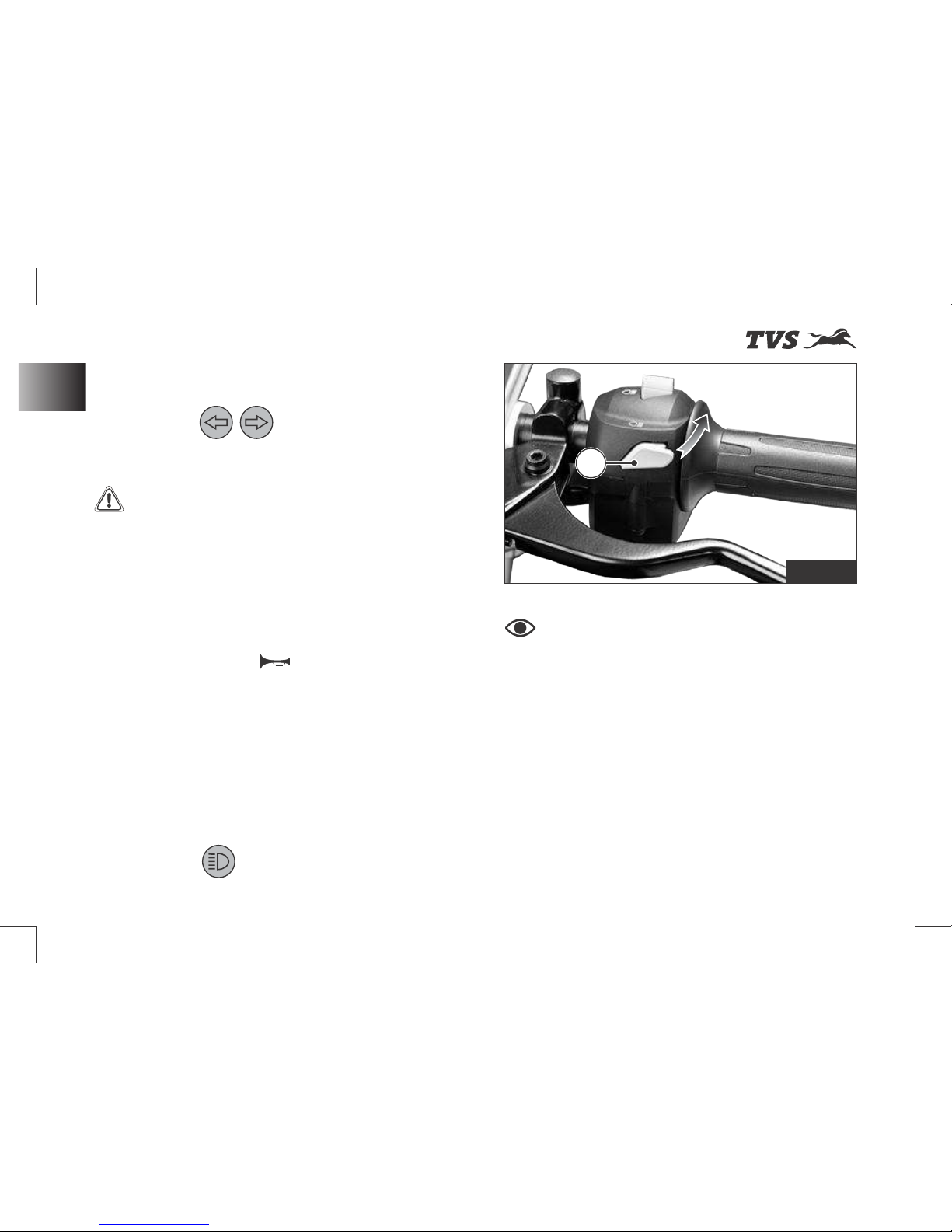
B) Switch turn signal (ref. Fig. 13)
w Push the switch towards ‘ ’ to flash LH
side turn signal lamps and towards ‘ ’ to
flash RH side turn signal lamps.
w Push the switch ‘IN’ to cancel.
Auto - Turn signal cut off
For your safety, if the turn signal lamps are ON
for more than 30 secs. and for 300 meters, the
turn signal will get switched OFF automatically.
Fig. 12 Fig. 13
41
Controls & Its Operations
C
A
B
Page 56
st
Revision:- Rev. 1, 1 Aug'2018 onwards
Warning
Even though there is auto
cut-off system provided for turn signal lamps,
it is the responsibility of the rider to switch the
turn signal lamp ON or OFF at the right time to
avoid an accident.
- When the ‘left’ or ‘right’ side turn signal
lamps are activated, respective turn signal
indicator ‘ ’ flashes along with it in
the instrument cluster.
KNOW YOUR MOTORCYCLE
Note
Pass by works only when the
beam control switch is in low beam position.
Fig. 14
D
C) Switch horn (ref. Fig. 13)
w Press the switch ‘ ’ to blow horn.
D) Pass-by switch (ref. Fig. 14)
w Press the switch intermittently to flash the
head lamp.
- Flashing the head lamp high beam
provides signal to the vehicles coming from
opposite direction during overtakes.
- If the high beam is flashed, the high beam
indicator ‘ ’ also flashes along with it in
the instrument cluster..
Controls & Its Operations
42
Page 57
st
Revision:- Rev. 1, 1 Aug'2018 onwards
KNOW YOUR MOTORCYCLE
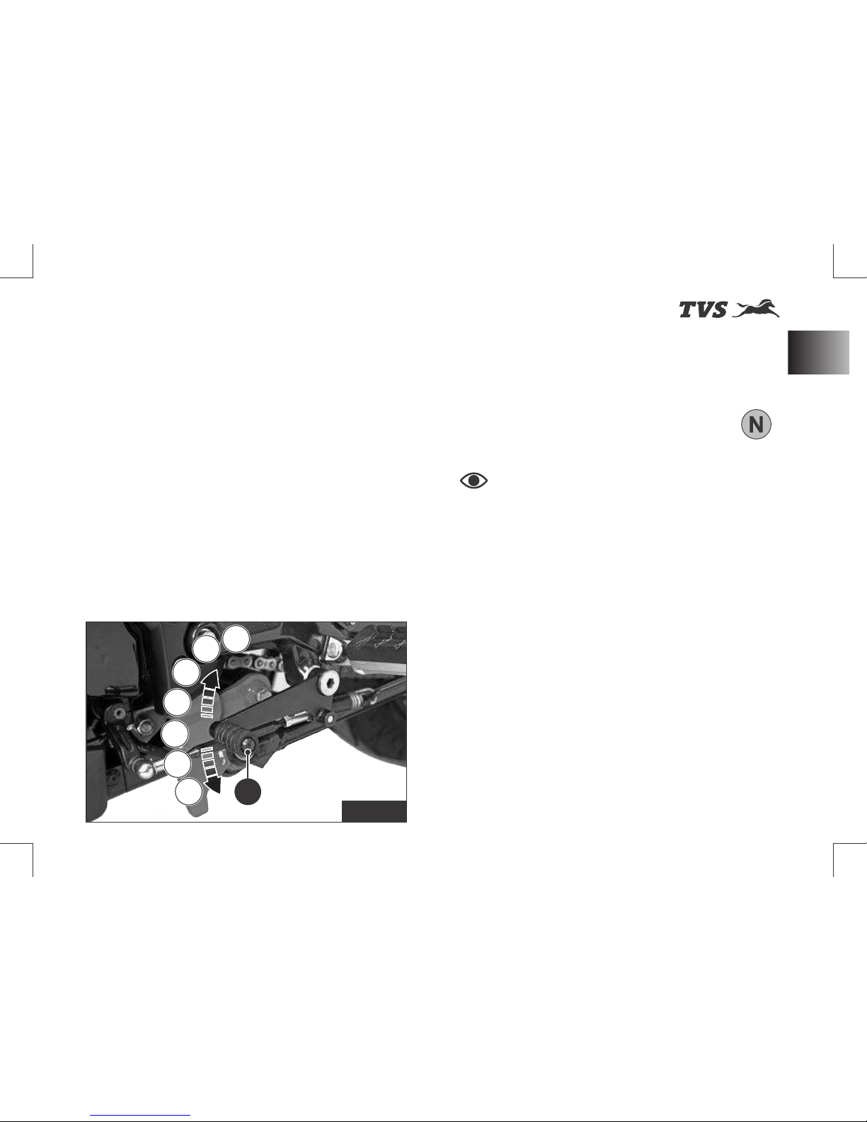
Gear Shift Pedal (ref. Fig. 15)
This motorcycle is equipped with a 6 speed
constant mesh transmission.
w To select the required gear or to bring the
vehicle to neutral, a gear shift lever (A) is
provided and it is located on the LH side of
the vehicle.
w To engage the 1st gear and to down shift
the gear press the pedal down.
w To engage 2nd, 3rd, 4th, 5th and 6th gear,
lift the pedal upwards.
- Each time you move the pedal you will be
engaging the next gear.
- Gear shift pedal returns to its position
(centre position) automatically when
released after shifting.
- Once the transmission is brought to
neutral position, the neutral indicator ‘ ’
illuminates.
Note
Apply the clutch when starting
the vehicle with gear engaged.
Gear shift pedal position can be adjusted as
per the convenience of the rider. Refer
page 64 for adjusting procedure.
A
5
6
3
2
N
1
4
Fig. 15
43
Controls & Its Operations
Page 58
st
Revision:- Rev. 1, 1 Aug'2018 onwards
KNOW YOUR MOTORCYCLE
Switch Assembly RH
Switch assembly RH is located in the handle bar
at RH side and has the following switches in it.
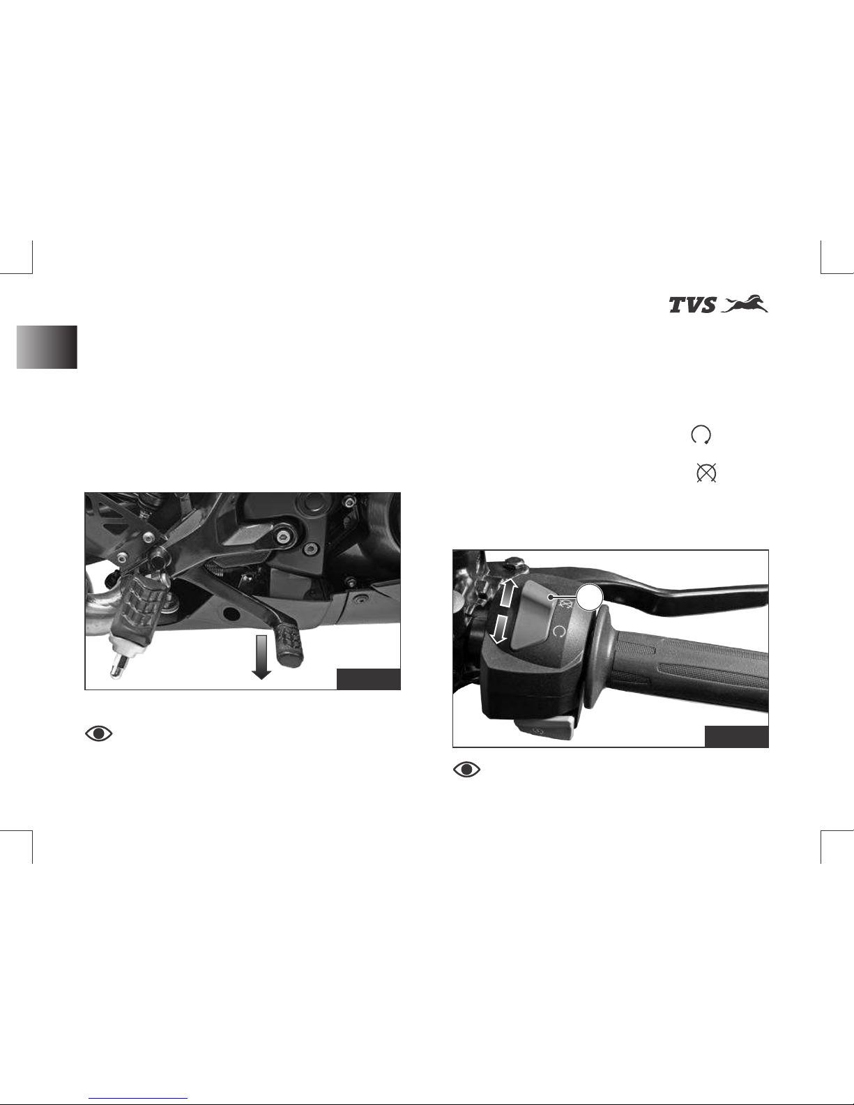
A) Switch engine cut-off (ref. Fig. 17)
w Press the switch towards you ‘ ’ to turn
ON (engine runs).
w Press the switch away from you ‘ ’ to turn
OFF (engine shuts).
- When turned OFF, only engine shuts
down but other DC systems will be active.
Note
Before starting, ensure to turn
ON the switch engine cut off.
Rear Brake Pedal (ref. Fig. 16)
Rear brake lever (A) is located on the RH side of
the vehicle.
w Push down the rear brake pedal with your
right foot to operate the rear brake.
- The system is operated by hydraulic and
just need to push the lever gently.
Note
Front brake lever and rear brake
pedal pulsates during the hard application of
brake which is normal. This pulsation occurs
because of ABS working.
Fig. 16
Fig. 17
A
Controls & Its Operations
44
Page 59
st
Revision:- Rev. 1, 1 Aug'2018 onwards
KNOW YOUR MOTORCYCLE
Warning
Do not operate the kill switch
when riding else you may fall due to rear
wheel locking.
This switch is mainly intended for use in
emergencies when you need to stop the
engine quickly.
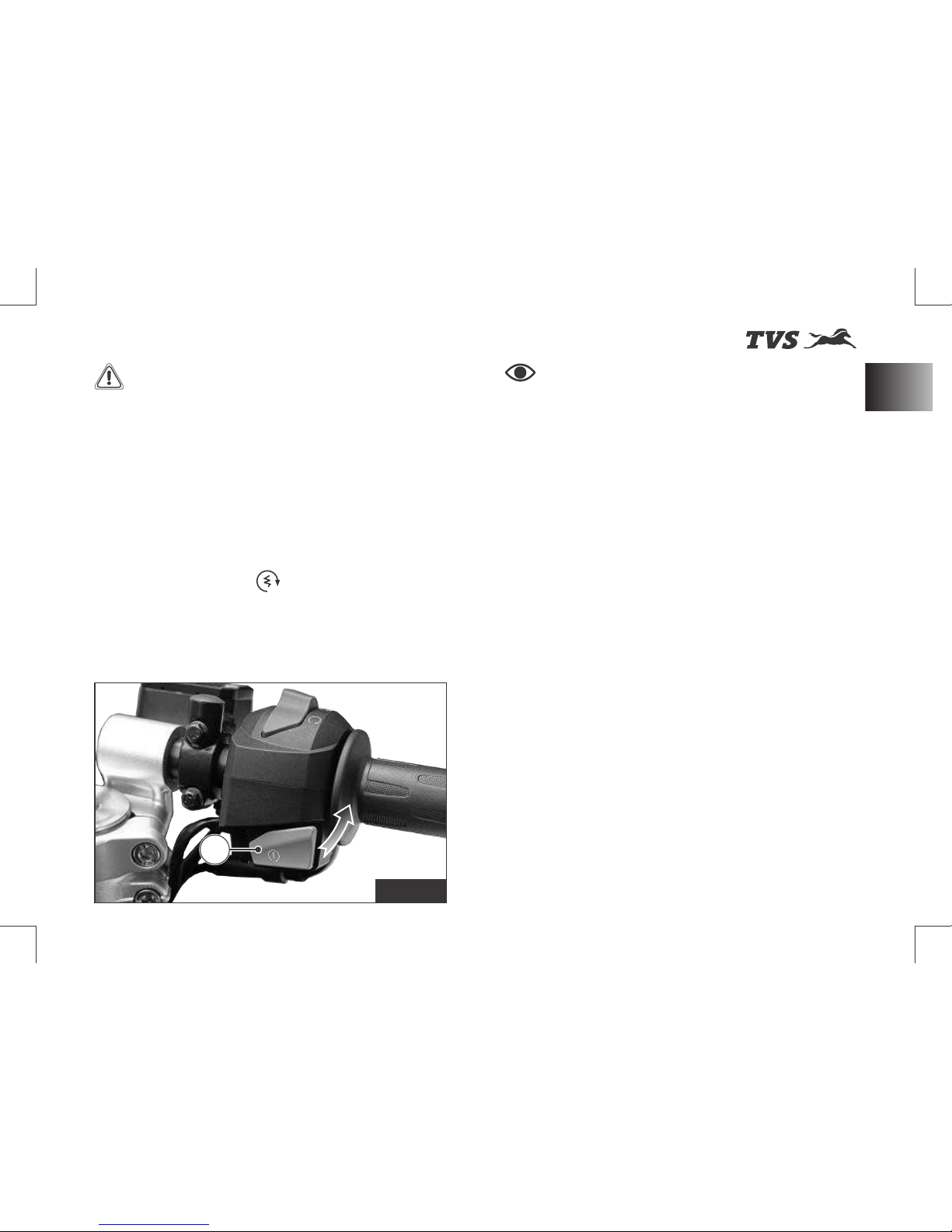
B) Switch electric starter (ref. Fig. 18)
w Press the switch ‘ ’ to start engine.
- Ensure the transmission is in neutral or
else press the clutch lever before engaging
the starter switch.
Note
If the electric starter switch is
pressed more than 3 seconds continuously,
the starter motor gets disabled automatically
and will not crank the engine. The motor
cranks the engine only after 1 second or if the
switch is released and repressed again.
Please remember that the electric starter
function will work only when the throttle
opening is less than 30%.
Re l e a s e t h e e l e c t r ic st a r t e r s w i tc h
immediately after engine starts.
Starter switch will not work if it is pressed
when the engine is running.
It is possible to start the vehicle with the side
stand ON and gear box in neutral. When
starting the bike with the gear engaged, apply
the clutch (the side stand must be up in this
case. If the side stand is in ON position, after
vehicle start engine stops while changing the
gear from neutral).
B
Fig. 18
45
Controls & Its Operations
Page 60
st
Revision:- Rev. 1, 1 Aug'2018 onwards
KNOW YOUR MOTORCYCLE
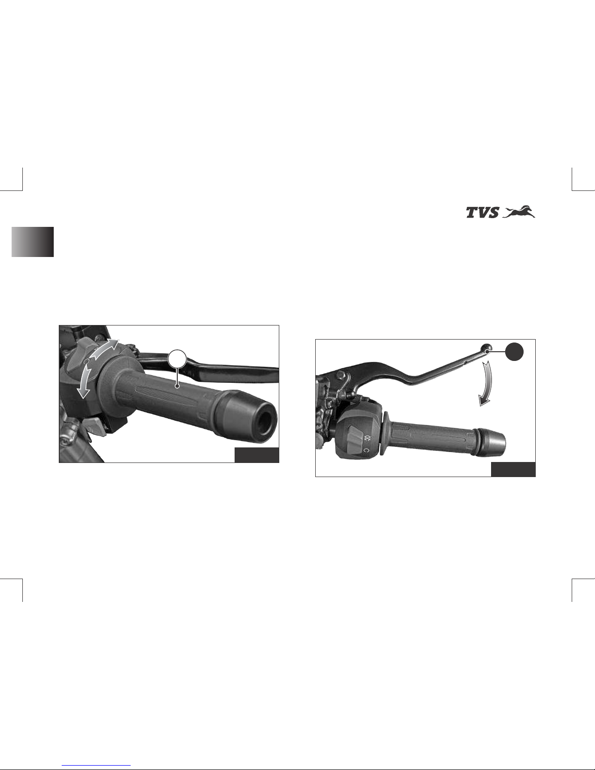
Throttle Twist Grip (ref. Fig. 19)
Throttle twist grip (A) is located in the handle bar
at RH side.
w Twisting the grip opens the throttle.
- Throttle grip spring back to the initial
position (idling speed) when released.
Front Brake Lever (ref. Fig. 20)
Front brake lever (A) is located in the handle bar
at RH side.
w Pull the lever towards the throttle twist grip
to operate the front brake.
- The system is operated by hydraulic and
just need to press the lever gently.
Fig. 19
Fig. 20
AA
Controls & Its Operations
46
A
Page 61
st
Revision:- Rev. 1, 1 Aug'2018 onwards
KNOW YOUR MOTORCYCLE
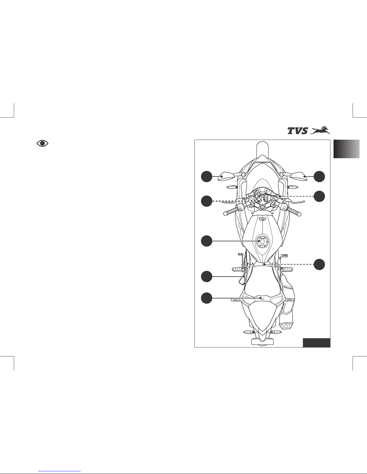
Major Components (ref. Fig. 21)
1) Rear view mirrors (ref. page 64)
2) Cooling system (radiator) (ref. page 48)
3) Fuel tank cap (ref. page 49)
4) Side stand (ref. page 51)
5) Seat lock (ref. page 53)
6) Adjustable rear shock absorber (ref. page 52)
7) Coolant reservoir (ref. page 48)
Note
This section shows the position
and operation of the major components of
your motorcycle.
Fig. 21
* Hidden items are marked with dotted lines
47
Major Components
1
2
4
1
5
3
7
6
Page 62
st
Revision:- Rev. 1, 1 Aug'2018 onwards
KNOW YOUR MOTORCYCLE
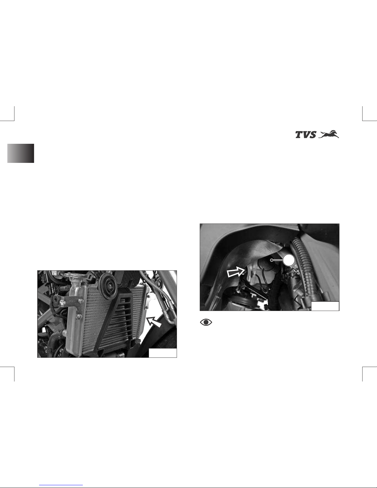
Cooling System (Radiator) (ref. Fig. 22)
A coolant is used in the motorcycle cools the
hot engine and ensures that operating the
vehicle at specified temperature which in-turn
avoids the risk of malfunctions.
w A radiator and cooling fan fitted in the
cooling system does job of cooling the
coolant used in the motorcycle by air
stream.
w Dirty cooling foils of radiator reduces the
cooling effect. Do the visual check and
ensure the cooling foils of the radiator are
not clogged with any dirt or mud. If so
contact TVS Motor Company Authorised
Main Dealer.
A coolant reservoir tank (A) is fitted on the right
side of the motorcycle below the side panels
(ref. Fig. 23).
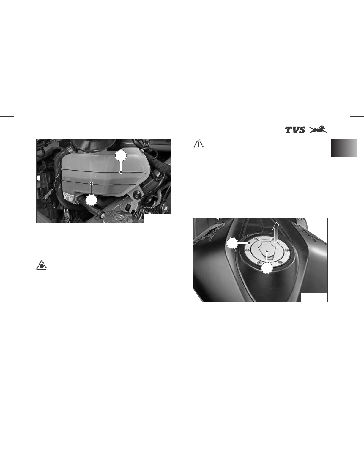
w Visually inspect the coolant level in the tank
(use a torch if required).
w The coolant level should be between
minimum and maximum level (1 & 2) on the
tank (ref. Fig. 24).
Fig. 22
Fig. 23
AA
Note
The cooling fan may switch ON
after the ignition is turned OFF to reduce the
heat and to protect the engine which is
normal. Need not panic.
48
Major Components
Page 63
st
Revision:- Rev. 1, 1 Aug'2018 onwards
Fig. 24
KNOW YOUR MOTORCYCLE
- Contact TVS Motor Company Authorised
Main Dealer for topping-up if the level in the
tank is lower than the minimum level.
Caution
Use o n ly recomme n ded
coolant (Glycentine G48, Coolant + Water;
@ 50:50 ratio; total filling 1 litre). Use of
improper coolant may cause damage, such
as corrosion in the engine parts, blockage of
th e c oo li n g pas s ag e or ra di a to r a nd
premature wear of the water pump seal.
Do not use tap water, or mineral water while
topping-up the coolant.
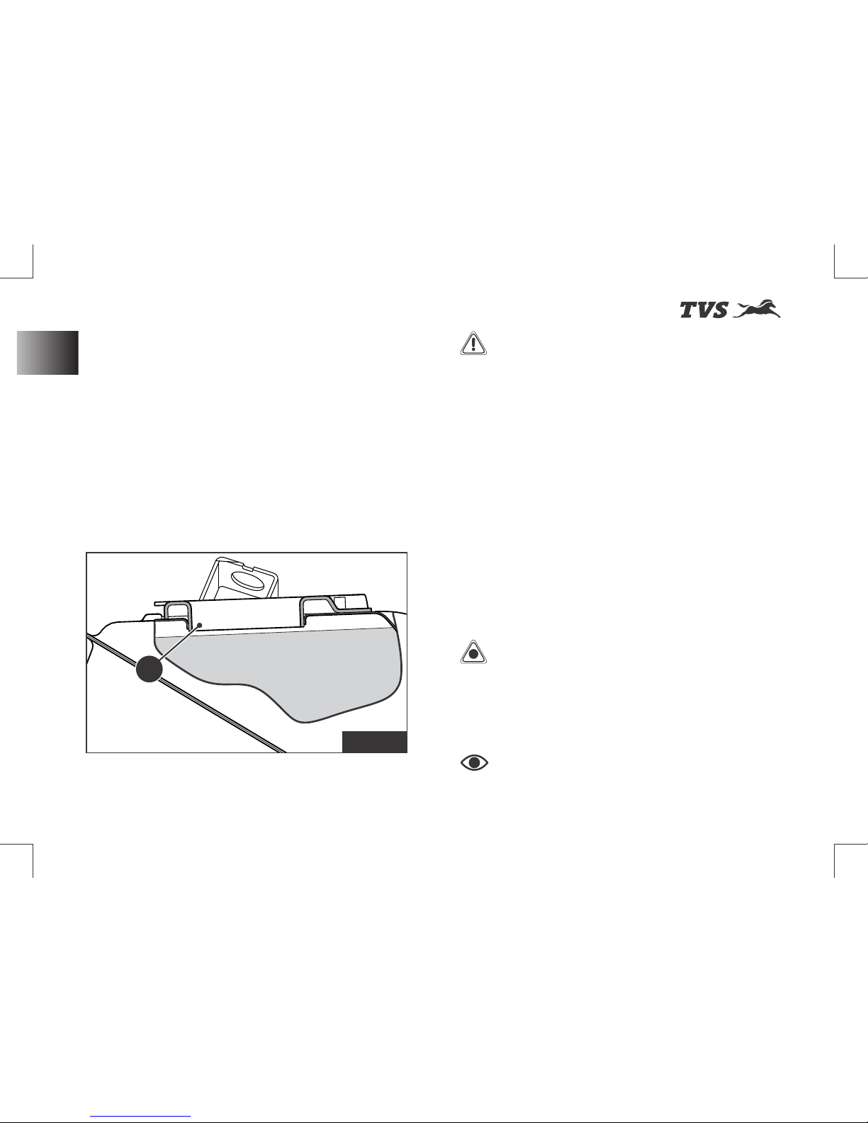
Fuel Tank Cap (ref. Fig. 25)
This motorcycle is equipped with a lockable fuel
tank cap (A).
To open:
w Lift the protection lid (B).
w Insert the control key into the lock. Rotate
the key a 1/4 turn clockwise and lift the cap.
1
2
Fig. 25
A
B
Warning
Coolant is poisonous and
hea lth hazard. Avoid contact between
coolant and body or clothing incase if you are
handling it.
49
Major Components
Page 64
st
Revision:- Rev. 1, 1 Aug'2018 onwards
Always make sure to close
the cap properly after every refilling to avoid
leak / evaporation.
To close:
w Push the cap down into its seat until hearing
a click sound.
w Turn the key anticlockwise to the initial
position and remove it.
w Close the protection lid.
Refueling (ref. Fig. 26)
w Never overfill the tank when refueling. The
fuel level always be below the brim of the
fuel tank neck (A).
* The fuel tank is not a measuring instrument and the
capacity of the fuel tank may slightly vary from the
indicated capacity.
Note
KNOW YOUR MOTORCYCLE
Warning
D o n o t s m o k e w h i l e
refueling. Do not use cell phones while
refueling. Avoid spilling of fuel on hot engine.
Refill petrol in well ventilated area. Switch
OFF the engine and ignition key while
refueling as petrol is highly inflammable.
Be sure there is no fuel trapped in the filler
recess.
To avo i d e v a po r a t i o n of p e t ro l a nd
deterioration of paint gloss due to ultra violet
rays and heat of sunlight, always park your
motorcycle in a covered parking.
Caution
Check for abnormal jerk /
noise while opening the cap / leak. If found
a n y, c on ta ct T VS Mo to r C o mp an y
Authorised Main Dealer.
Fig. 26
FUEL
A
Major Components
50
Page 65
st
Revision:- Rev. 1, 1 Aug'2018 onwards
KNOW YOUR MOTORCYCLE
Caution
B e f o r e su p po r t i n g t h e
motorcycle on side stand, make sure that the
supporting surface is hard and flat. Do not
park the motorcycle on soft ground, gravel
etc., else the bike may fall down.
While parking the motorcycle in downhill
tracks, always park the bike in such a way that
the rear wheel of the bike facing downhill.
Ensure not to disturb the side stand switch
setting.
Warning
Do not sit on the motorcycle
when it is supported on side stand.
Note
It is possible to start the
vehicle with the side stand ON and gear box in
neutral. When starting the bike with the gear
engaged, apply the clutch (the side stand
must be up in this case. If the side stand is in
ON position, after vehicle start engine stops
while changing the gear from neutral).
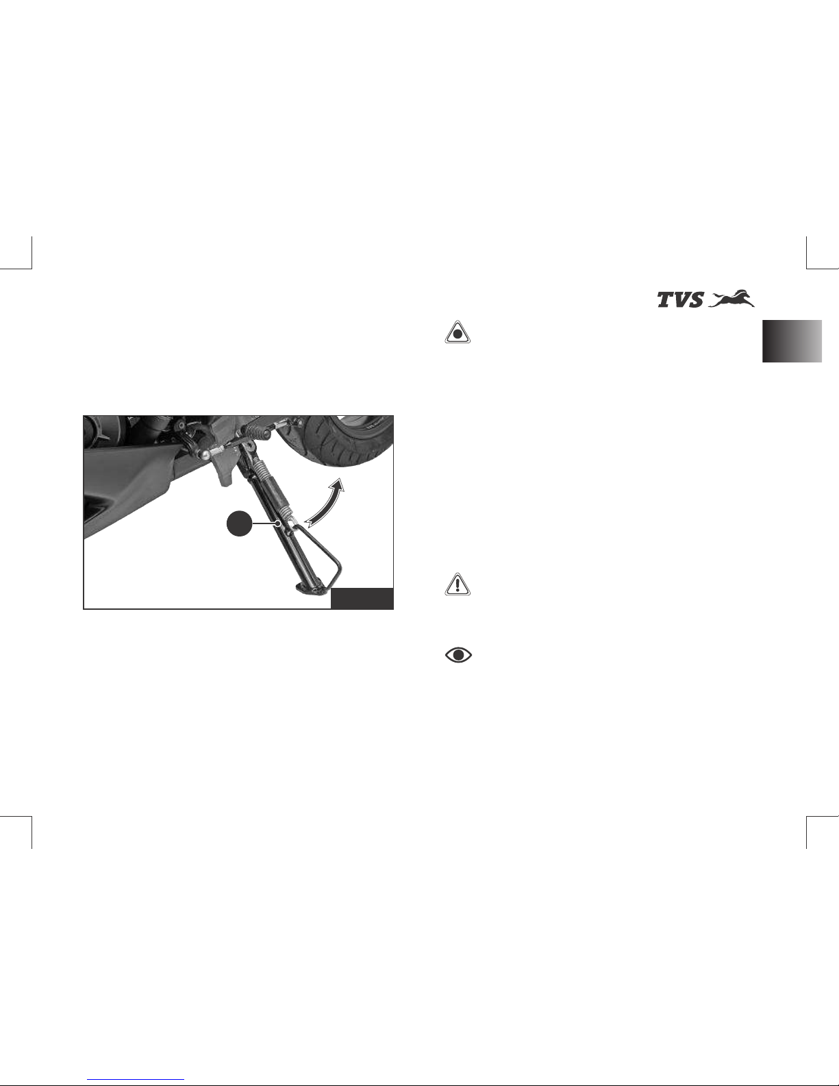
Side Stand (ref. Fig. 27)
Side stand (A) can be operated with your foot.
To support your motorcycle on side stand:
w Hold the motorcycle handle bars with both
the hands and push down the stand with
your foot until the stand is fully extended.
w Lean the motorcycle to the left until the
stand contact the ground.
w To move back the side stand to its original
position (horizontal position), tilt the
motorcycle to the right and, at the same
time, lift the stand with your foot.
Fig. 27
A
51
Major Components
Page 66
st
Revision:- Rev. 1, 1 Aug'2018 onwards
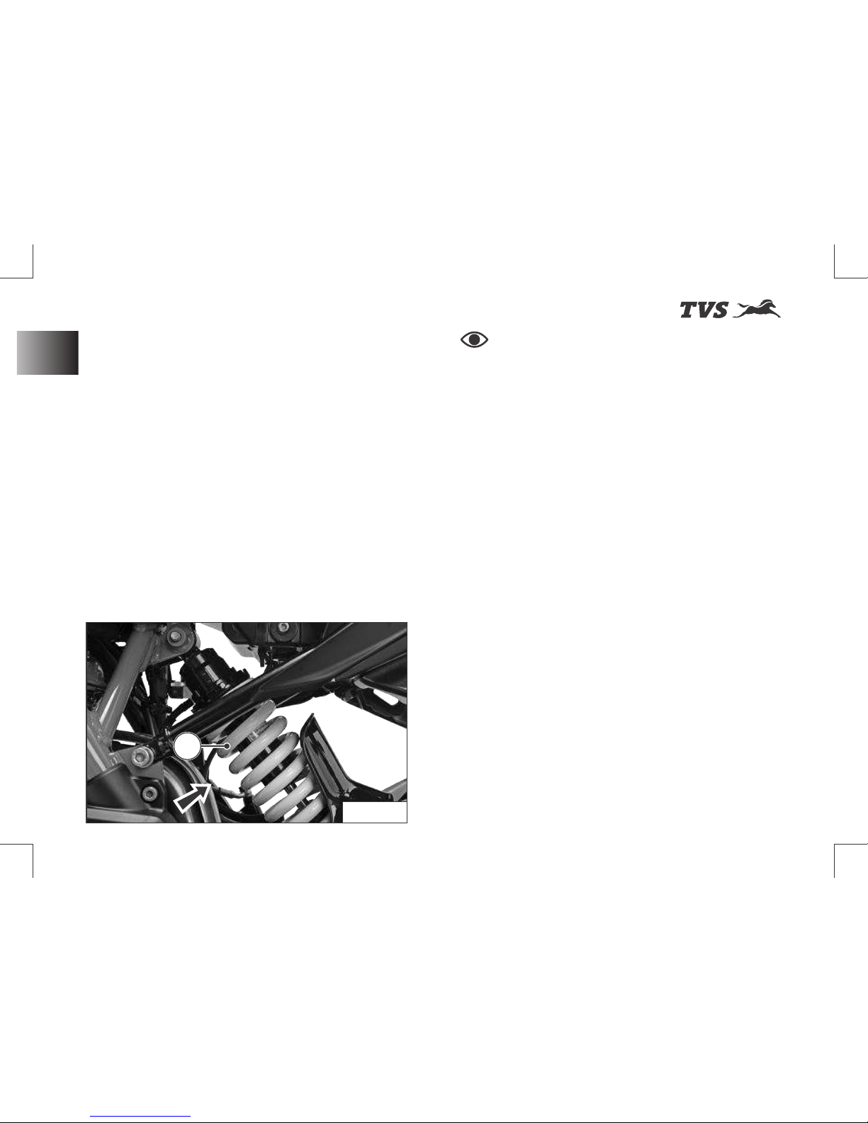
Rear shock absorber (ref. Fig. 28)
Your motor cycle is fitted with 10 step
adjustable gas filled rear shock absorber
(A) to meet different load and driving conditions.
w The pre-load of the shock absorber can be
adjusted to suit your requirements. Refer
page 65 for pre-load adjustment procedure.
w Inspect the shock absorber for any dirt or
mud accumulation on it or any fluid leak.
- If found any, clean them properly using a
soft cloth and brush.
- If any leak is found contact TVS Motor
Company Authorised Main Dealer.
KNOW YOUR MOTORCYCLE
Note
During time of delivery of the
motorcycle, the rear shock absorber is
adjusted to the standard configuration.
Fig. 28
AA
Major Components
52
Page 67
st
Revision:- Rev. 1, 1 Aug'2018 onwards
KNOW YOUR MOTORCYCLE
Seat Lock (Rider and Pillion Seat)
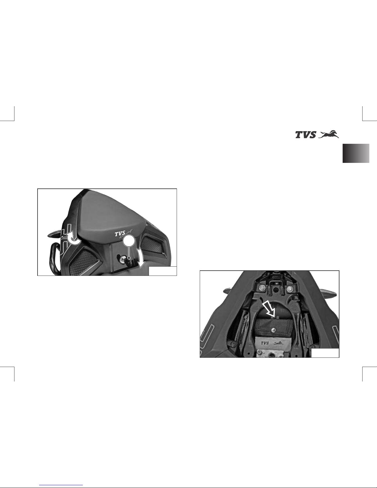
This motorcycle is equipped with a lockable
rider and pillion seats. The seat lock (A) is
located between the rider and pillion seat as
shown (ref. Fig. 29)
To open pillion seat:
w Insert the control key into the seat lock.
Rotate the key in clockwise until the lock is
released.
w Pull and release the front section of the seat
first, slide the seat towards vehicle front
direction.
w Ensure the hook underneath got released
from frame and take out the seat.
To close pillion seat:
w Slide the rear end of the seat bottom
underneath the frame hook.
w Locate the seat lock pin into seat lock latch
and gently press (at the front end).
- Finally ensure that the seat is fastened
securely to the frame.
To open the rider seat:
w Remove the pillion seat as explained earlier
and take out the control key from the seat
lock without fail.
w Take off the tool kit from the storage (ref.
Fig. 30)
Fig. 29
A
Fig. 30
53
Major Components
Page 68
st
Revision:- Rev. 1, 1 Aug'2018 onwards
KNOW YOUR MOTORCYCLE
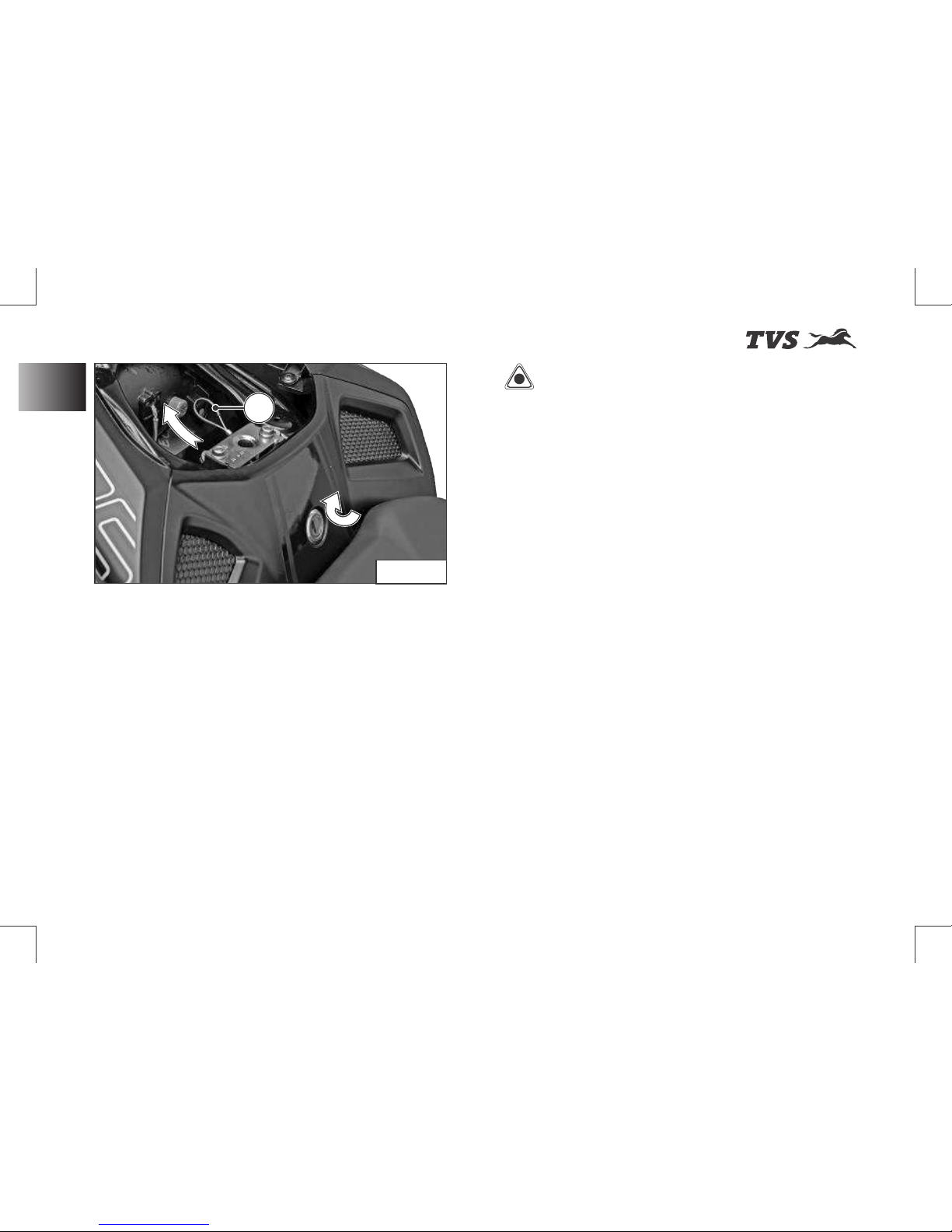
w Pull the seat release cable (A) to release the
seat lock (ref. Fig. 31).
w Keeping seat release cable pulled, lift the
seat from rear and slide it backward.
To close the rider seat:
w Slide the front end of the seat bottom
underneath the frame hook.
w Locate the lock pin of the seat into seat lock
latch and gently press at the rear end.
- Finally ensure that the seat is fastened
securely to the frame.
Caution
Take the control key out from
the seatlock without fail during the removal of
rider seat, to avoid damage to the seat / lock.
Make sure that the seats are locked securely
in position after reassembly.
Major Components
54
A
Fig. 31
Page 69
st
Revision:- Rev. 1, 1 Aug'2018 onwards
RIDING YOUR MOTORCYCLE
55
Before Riding
Before Riding
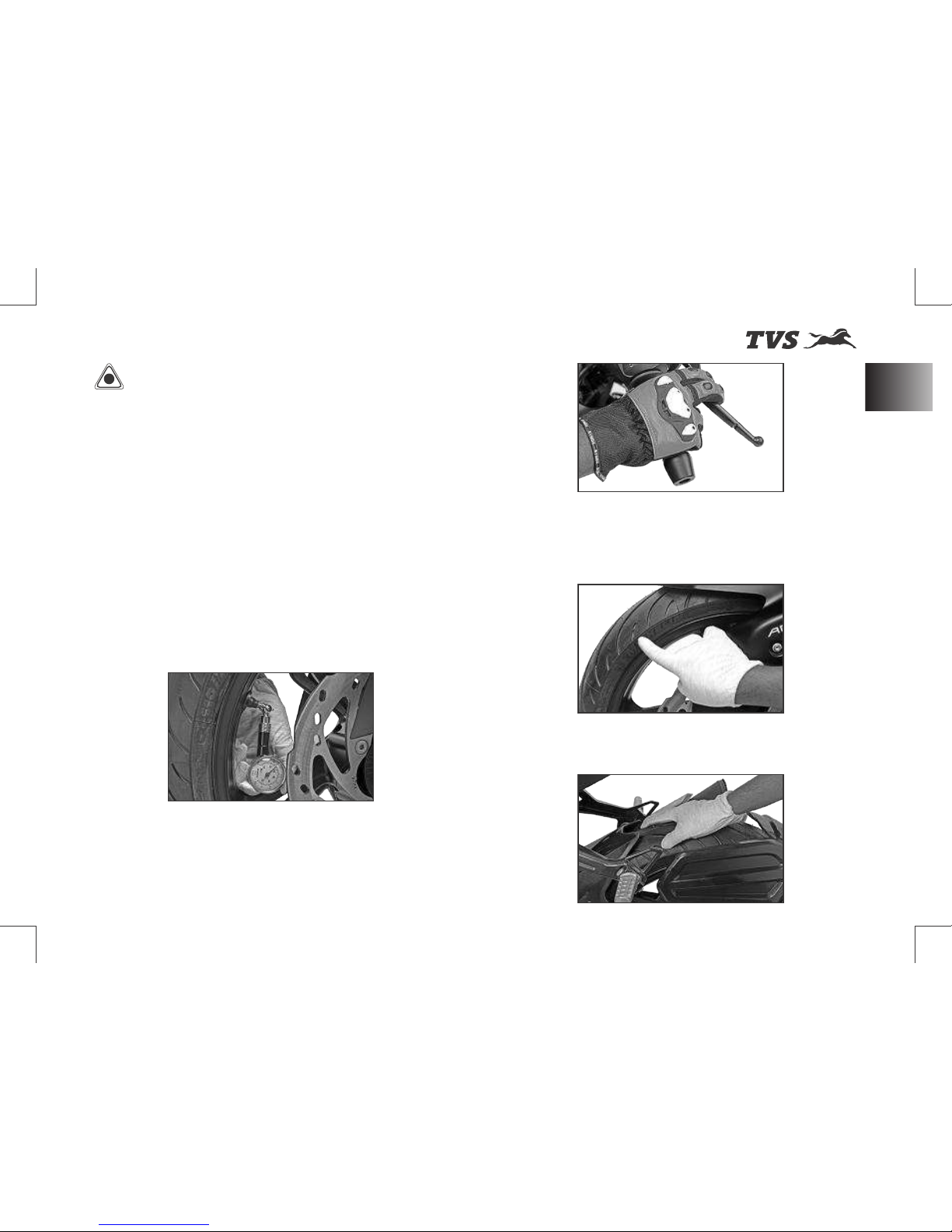
w Ensure that tyre pressure is as per
spe cif ic a ti on. Lo w er or h ig h er tyre
pressures are likely to cause instabilities in
motorcycle behaviour.
w Check operation of throttle, clutch, and
brakes as well as free play on front and rear
brakes. Pump in the brake lever and pedal a
few times to ensure proper bleeding.
Caution
Running-in is essential to
preserve engine life and performance over
t i m e . K e e p i n g t o t h e r u n n i n g - i n
recommendations will ensure longer engine
life and reduce the need for overhauls and
re-tuning. Refer page 01 for running-in
information.
w Ch e ck b o t h ty re s fo r a ny we ar o r
abnormalities. Ensure that wear is not
below ‘Tread wear indicator’ mark.
w Check steering freeness, front and rear
wheel freeness and alignment.
Page 70
st
Revision:- Rev. 1, 1 Aug'2018 onwards
RIDING YOUR MOTORCYCLE
56
Before Riding
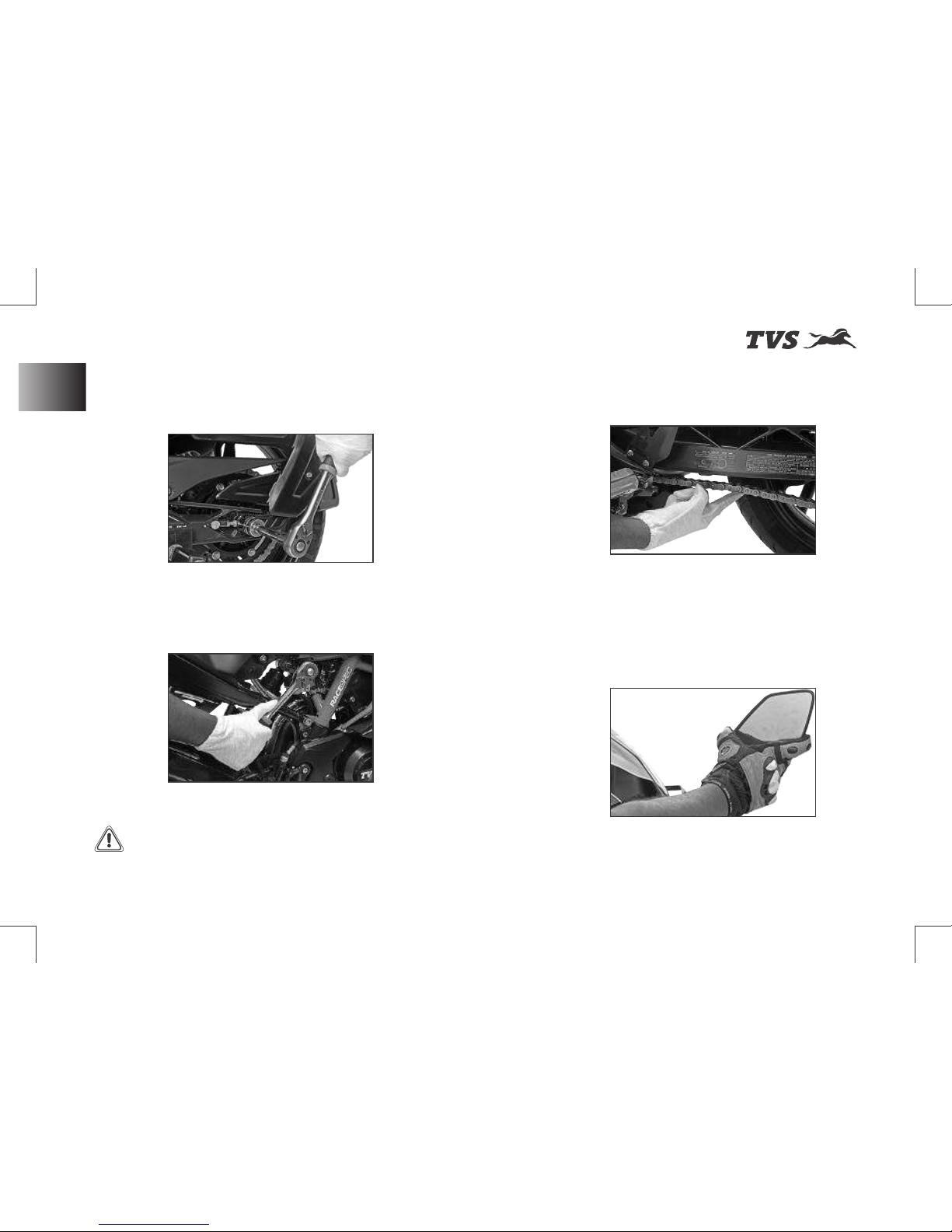
w Check tightening of wheel axle nuts, swing
arm nut and steering nut.
w Also check tightening of front fork and
shock absorber mounts.
Warning
Failure to carry out these
checks before riding may result in damage to
the motorcycle and injury to the rider.
w Ch e ck fo r c ha i n sl a c k n e s s as p er
specification.
w Adjust mirror position to have optimum rear
visibility. If you prefer track riding sans rear
view mirrors, please remove and preserve
them carefully.
Page 71
st
Revision:- Rev. 1, 1 Aug'2018 onwards
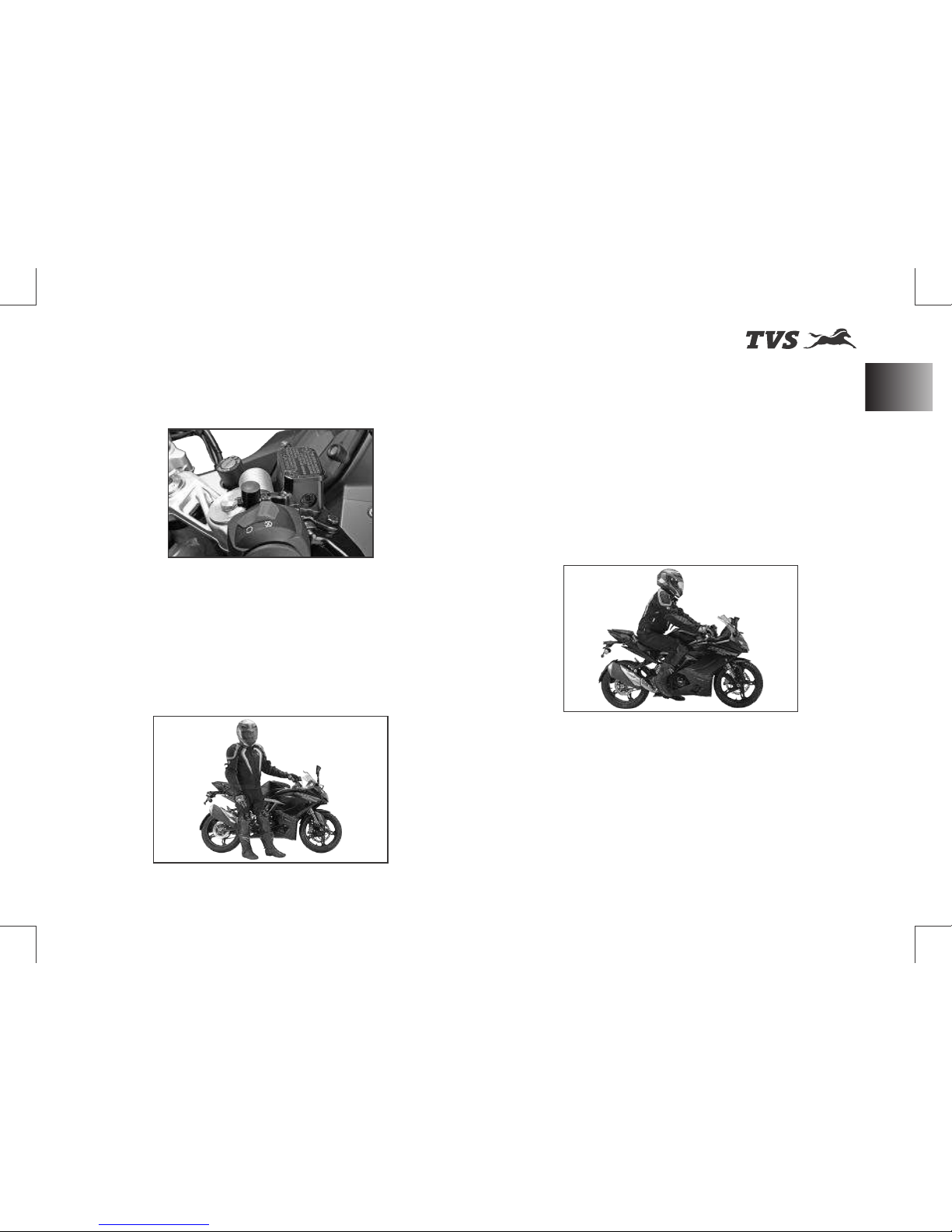
w Check engine oil, brake oil and coolant oil
levels.
While Riding
w Wear all necessary safety gears (Helmet,
Jacket, Knee guards, Shoes and Gloves)
before riding.
w Riding Posture - While riding, sit slightly
behind the fuel tank. Body position should
be re l ax e d s uc h t h at ba ck i s v er y
comfortable. Shoulders and arms should
also be relaxed with slight bend in the arm
as shown. Hold the handle bar with a good
grip. Fuel tank should be firmly held by the
thighs while riding. This will help maintain
stability of the bike at all speeds.
w While riding, have a relaxed posture with
wide vision.
w Ensure smooth operation of throttle, do not
abruptly open the throttle especially in the
corners
w Don’t throttle while entering a turn. You may
accelerate progressively while exiting a turn.
w Do not shift gears in a turn.
RIDING YOUR MOTORCYCLE
57
While Riding
Page 72
st
Revision:- Rev. 1, 1 Aug'2018 onwards
Starting the Engine
w Turn-on the ignition key (ref. page 39).
Ensure that the neutral indicator ‘N’ (C4,
ref. page 20) is ON.
w Check that the engine cut-off switch is
positioned at run mode ‘ ’ and press the
starter button ‘ ’ (ref. page 45).
Warning
Before starting the engine,
familiarise your self with the controls which
you need to use while riding (ref. page 38).
Note
It is possible to start the
vehicle with the side stand ON and gear box in
neutral. When starting the bike with the gear
engaged, apply the clutch (the side stand
must be up in this case).
If the battery voltage is too low, the system
automatically disables the self-start function.
Caution
Do not rev the engine when it
is cold. Allow some time for the oil to warm up
and to reach all points that needs lubrication.
w Avoid abrupt hard braking, If hard braking is
inevitable, release throttle and apply front
and rear brakes in a progressive manner.
w Don't brake too hard while the vehicle is
leaning, as vehicle may skid easily.
w Tyre grip reduces in cold conditions. It will
take about 5 kms of riding for tyres to reach
optimal temperatures.
w New tyres require running in for 20 kms
before you can get the maximum grip.
RIDING YOUR MOTORCYCLE
58
Starting the Engine
Page 73
st
Revision:- Rev. 1, 1 Aug'2018 onwards
Moving the Vehicle
w Disengage the clutch by pressing the
control lever.
w Press the gear shift pedal downwards with
the tip of your foot to engage the first gear.
w Increase the engine speed by turning the
throttle twist grip while gradually releasing
the clutch lever; the motor cycle start
moving forward.
w Release the clutch lever and increase the
engine speed (increase the throttle).
w To up shift the gear, close the throttle to
slow down the engine speed, disengage
the clutch, lift the gear shift pedal up and
release the clutch lever.
- To down shift the gear, proceed as follows:
release the throttle twist grip, pull the clutch
lever, increase the engine speed for a
moment to allow the gears to synchronise,
down shift the gear and release the clutch
lever.
- Use controls wisely and promptly: when
riding uphill do not hesitate to down shift the
gears as soon as the vehicle tends to slow
down. This will avoid stressing the vehicle
and the engine abnormally.
RIDING YOUR MOTORCYCLE
59
Moving the Vehicle
Caution
Avoid sudden acceleration,
as this may lead to misfiring, improper
engagement of transmission (snatching).
Do not pull the clutch lever longer than
necessary after engaging the gear. Otherwise
the friction plates in clutch may get overheat
and wears out quickly.
Page 74

st
Revision:- Rev. 1, 1 Aug'2018 onwards
RIDING YOUR MOTORCYCLE
60
Braking & Parking
Braking
w Slow down the speed in right time, shift
down the gear to use the engine brake, then
apply both the brakes.
w Pull the clutch lever before stopping the
motorcycle to avoid sudden stoppage of
engine.
Stopping the motorcycle
w Reduce speed, close the throttle and down
shift the gears. Bring the transmission to
neutral position just before the vehicle
stops.
w Apply the brakes and bring down the
motorcycle to complete stop.
w Turn OFF the ignition.
Parking
w Stop the motorcycle. Place it on the side
stand on a flat firm surface (ref. page 51).
w Turn the steering all the way to ‘left’ or ‘right’
and lock as explained in page 39. Take out
the control key from the ignition lock.
w If the vehicle is parked in a garage or other
indoor area, make sure that there is a proper
ventilation and the motorcycle is not nearer
to a source of heat.
Warning
Use both front and rear
brake for effective braking.
When riding in the rain or on slippery
surfaces, braking capacity is significantly
reduced. Always use the brakes very gently
and carefully when riding under these
conditions.
When riding downhill, shift down to the lower
gears to use engine as a brake.
Caution
Keeping the brake applied
continuously causes the brake pads (friction
materials) to overheat and reduces the
braking effectiveness which is dangerous.
Note
You may switch ON the hazard
lamps if the vehicle is parked in hazardous
location. Refer page 18 for hazard lamps
function.
Page 75
st
Revision:- Rev. 1, 1 Aug'2018 onwards
RIDING YOUR MOTORCYCLE
61
Fuel Recommendation
Warning
The engine and the exhaust
system might be very hot even after switching
OFF the engine. Care should be taken not to
touch the exhaust system with any part of
your body.
Park the vehicle in a place where the
pedestrians or children are not likely to touch
the hot surface.
Do not park the vehicle near dry grass or any
other flammable resources which might
catch fire.
Using padlocks or other locks like brake disc
locks, rear sprocket locks etc. to prevent the
move me nt o f t he moto rcy cl e i s ver y
dangerous and may affect the motorcycle
operation and safety of the users.
Fuel Recommendation
w Use BS IV / Unleaded petrol only. The petrol
should be minimum 91 octane by research
method.
- Petrol mixed with ethanol (regular
unleaded, maximum 14% ethanol) will have
impact on engine components. Contact
TVS Motor Company Authorised Maine
Dealer for usage.
- Refer page 49 for fuel filling procedure.
Caution
Never mix oil in the petrol.
Always fill fuel from reputed and reliable fuel
stations.
Note
Use fuel additives in petrol (as
recommended by additive manufacturer) for
low carbon deposition.
Page 76

st
Revision:- Rev. 1, 1 Aug'2018 onwards
RIDING YOUR MOTORCYCLE
62
Fuel Economy Tips
Checks and Tips for Better Fuel Economy
w Carry out the periodic maintenance checks
as specified in this manual (ref. page 69).
- Regular maintenance checks will save fuel
while ensuring trouble-free, enjoyable and
s a f e r id i n g b e s i d es k e e pi n g th e
environment clean.
w A dirty defective spark plug leads to
wasta g e o f fuel due to i n co m pl ete
combustion.
- Replace the spark plug every 20000 km.
Use recommended plug only.
w A dirty air cleaner element restricts airflow
and reduces fuel economy.
- Replace the air cleaner element every
10000 km.
w Increase in engine rpm during acceleration,
without increase in road speed indicates
the clutch slip. A slipping clutch causes high
fuel consumption and engine overheating.
- Adjust the clutch play as explained in page
76 if the above malfunction is observed.
- If the condition persists even after
adjusting the clutch play contact TVS Motor
Company Authorised Main Dealer.
w Dirty or less engine cum transmission oil
increases the friction between various parts
of the engine and reduces engine life, and
increases the fuel economy.
- Inspect the engine cum transmission oil
level as explained in page 74 and top-up if
necessary.
- Engine cum transmission oil should be
replaced as per the maintenance schedule
without fail.
- Always use recommended engine oil
only (ref. page 119).
w Low tyre pressure has adverse effects on
the vehicle. The drag on the vehicle
increases resulting in decreased fuel
economy. Further more handling may be
affected adversely.
- Check tyre pressure regularly and inflate
them to recommended pressure. Refer
page 82.
- Never use tyre which are worn-out beyond
the permissible limit.
w Ch e ck an d e ns ure the d ri ve c ha in
slackness. Excess slackness lead to higher
fuel consumption (ref. page 85).
Page 77

st
Revision:- Rev. 1, 1 Aug'2018 onwards
RIDING YOUR MOTORCYCLE
63
Fuel Economy Tips
w Check and ensure the free movement of
wheels by rotating them to avoid wastage of
fuel.
w A racing start from rest at full throttle will
waste fuel and damage the engine. It is also
creates potentially hazard traffic situation.
w Fuel is wasted whenever the rider suddenly
accelerate or apply brake.
w While waiting for someone or stopping in
signals for long time, if the engine is kept
running at idle speed, leads to unnecessary
wastage of fuel.
w Anticipate corners and slopes as well as the
tra f fic conditions. Unnecessary and
frequent braking reduces the fuel economy.
Page 78
st
Revision:- Rev. 1, 1 Aug'2018 onwards
GENERAL ADJUSTMENTS
64
Mirrors & Gear Shift Pedal Adjustment
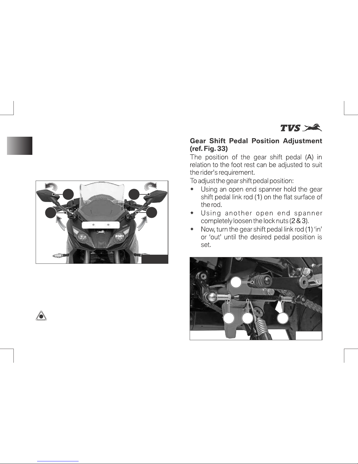
Rear View Mirrors LH & RH (ref. Fig. 32)
Adjustable rear view mirrors (LH & RH) are
provided with your bike. These mirrors can be
adjusted to your convenience by following the
procedure given below:
w Move the rear view mirror stem (A) to the
desired position (forward or backward).
w Tilt the mirror portion (B) till the clear vision
is obtained (up or down).
Caution
Neve r tr y to ad ju st t he
position by moving the hole mirror assembly,
as this could break the mirror.
Fig. 33
Fig. 32
3
AA
A
A
2 1
B B
Page 79
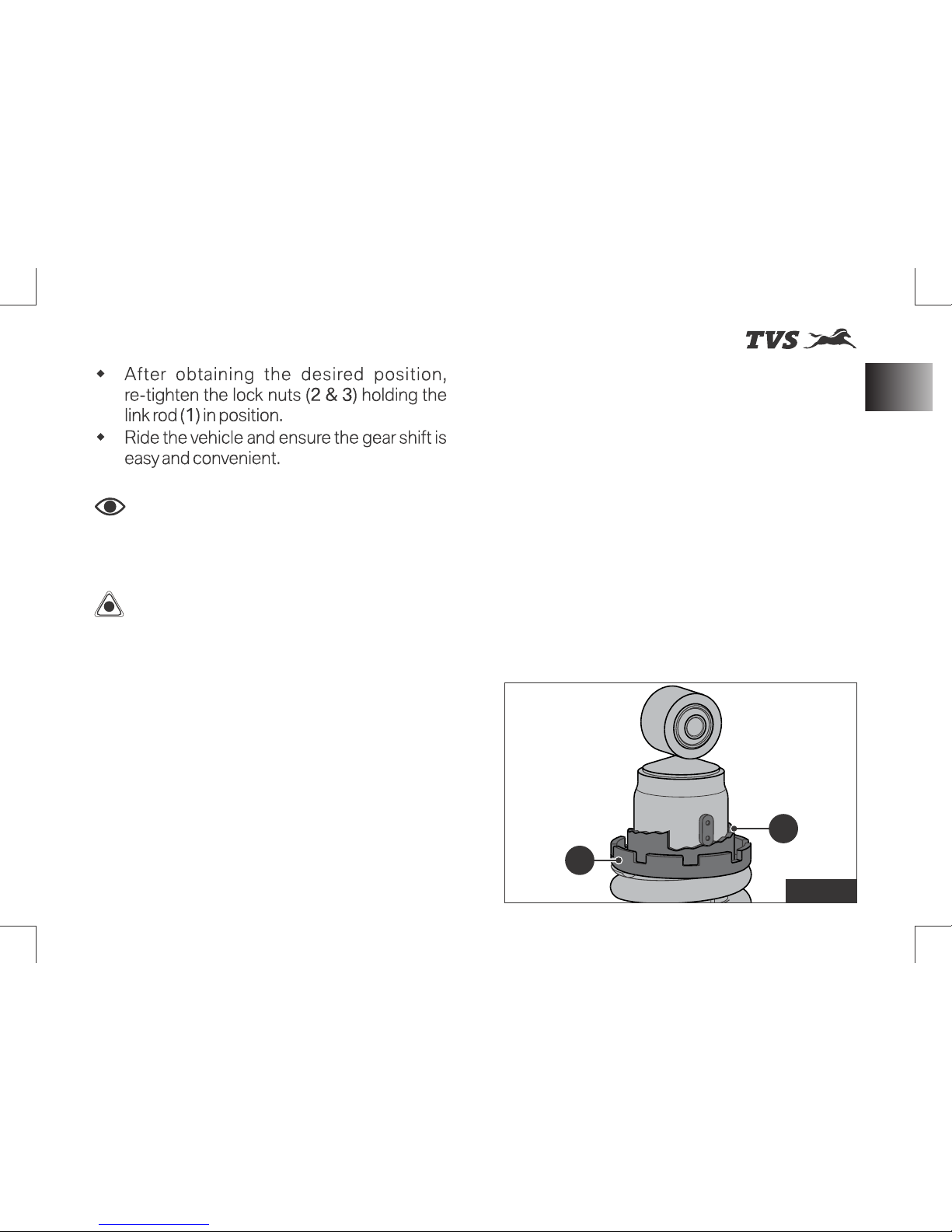
st
Revision:- Rev. 1, 1 Aug'2018 onwards
GENERAL ADJUSTMENTS
65
Rear shock absorber Pre-load Adjustment
Caution
Do not loosen the link rod to
the maximum position (till the last thread).
Else, it may come out from the shifting
mechanism during ride.
Note
Lock nut (2) has a left-hand
thread and should be loosened or tightened
in opposite direction.
Re a r sh o c k a b s o r b e r ’ s P r e - L o a d
Adjustment (ref. Fig. 34)
The pre-load of rear shock absorber can be
adjusted as per rider’s convenience and the
load (weight of rider, passenger and luggage) on
the vehicle.
There are 10 notches (1) for adjusting the preload of the shock absorber. Normally, the shock
absorber’s pre-load adjuster (2) will be
positioned at 3rd notch (standard setting).
Increase the spring pre-load (shift to higher
notches) for heavier rides.
Decrease the spring pre-load (shift to lower
notches) for lighter rides.
Fig. 34
2
1
Page 80
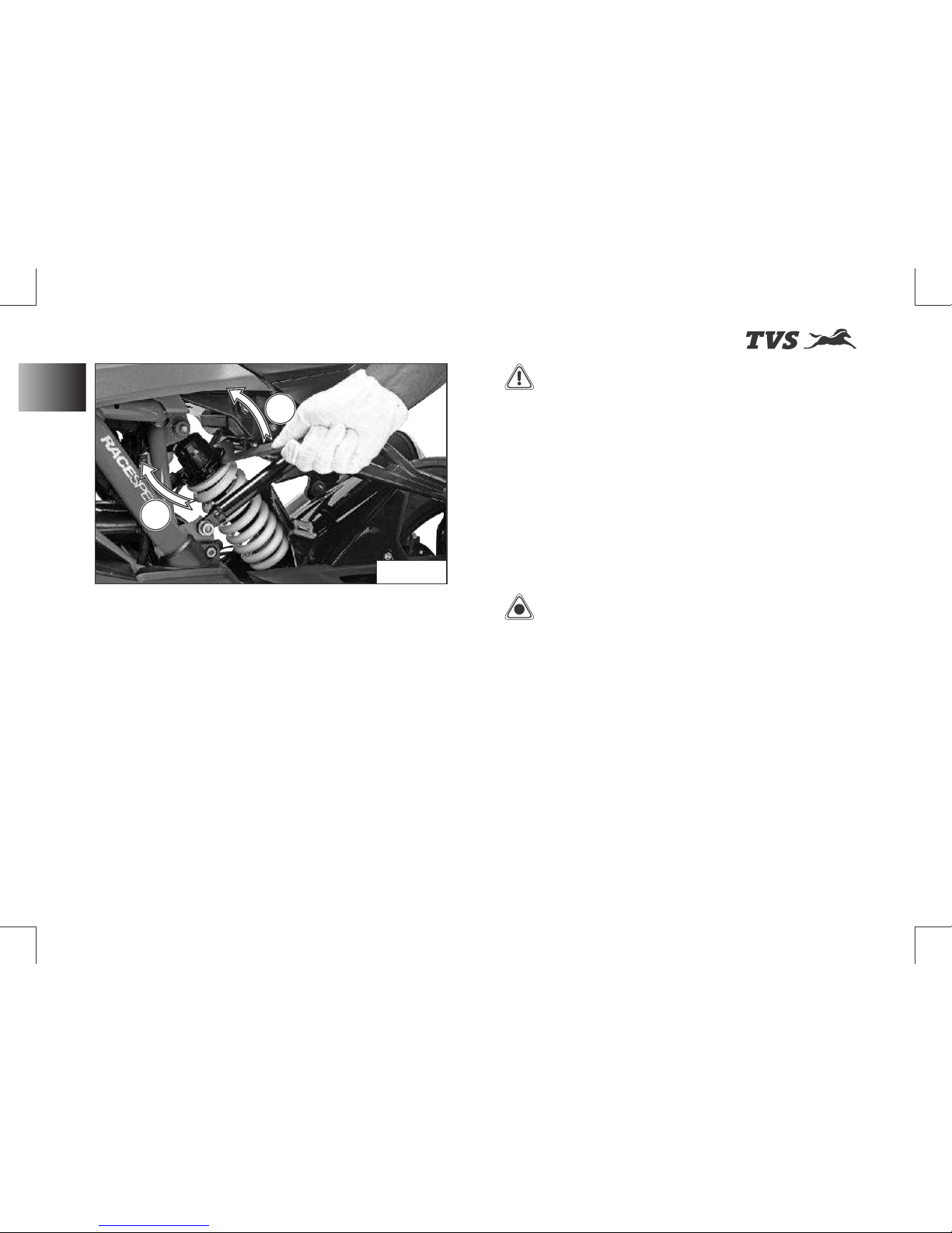
st
Revision:- Rev. 1, 1 Aug'2018 onwards
GENERAL ADJUSTMENTS
66
Rear shock absorber Pre-load Adjustment
To adjust the shock absorber’s pre-load:
w Place the motorcycle on its stand on a firm
and flat surface.
w Locate the adjuster shock absorber rear and
handle ring spanner of tool kit (ref. page
103) properly into the notches of pre-load
adjuster (ref. Fig. 35).
w Carefully rotate the adjuster clockwise (A) to
increase the pre-load (hard suspension).
w Else, rotate the adjuster in anti-clockwise
(B ) to de cre as e t h e pre- lo ad (s of t
suspension).
Warning
The rear shock absorber
contains highly compressed gas. Do not try
to open or disassemble it in any way.
Take a special care while turning the pre-load
adjuster because, your hand may be striking
against the other parts of the motorcycle if
the adjuster spanner slips out of the pre-load
adjuster notch.
Caution
Rear shock absorber to be
adjusted only on the left side of the vehicle.
Adjust step by step (3rd to 4th notch and so
on). Do not go at a stretch as it will damage
the adjuster.
Fig. 35
B
A
Page 81
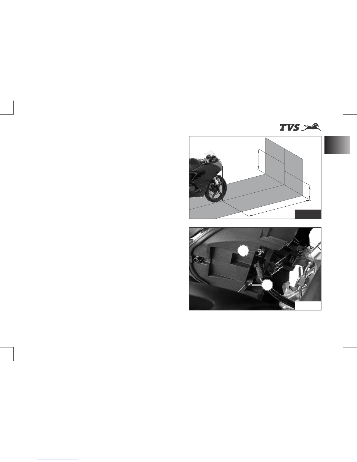
st
Revision:- Rev. 1, 1 Aug'2018 onwards
GENERAL ADJUSTMENTS
67
Head Lamp Aiming
Head Lamp Aiming
To check and adjust the head lamp focus:
w Place the motorcycle upright in a uniform
flat surface while ensuring the head lamp
center (A) is 5 meter away from a vertical wall
or screen (B). (ref. Fig. 36)
w Inflate the tyres to the correct pressure.
w Keeping the motorcycle at right angles to its
longitudinal axis switch on the ‘Low beam’
of head lamp.
Two projector lamps need to be adjusted
independently as mentioned below:
a. RH side projector adjustment:
w Mask the LH side projector lamp using a
black color cloth.
w Adjust the RH side projector lamp adjuster
(C) clockwise (Downward) or in anticlockwise (Upward) and match the low
beam cut-off line to the marking line (D)
(500 mm) on a vertical wall or screen.
(ref. Fig. 36 & 37)
b. LH side projector adjustment:
w Remove the cloth from LH side projector
and mask RH projector lamp.
* The specification for head lamp beam adjustment is
applicable only for India. Owner’s of other countries
are advised to adopt the local rules and regulations.
Fig. 37
C
E
F = 660 mm
(LH side)
D = 500 mm
(RH side)
A = 5000 mm
Fig. 36
V
ertical scr
een (B)
Page 82
st
Revision:- Rev. 1, 1 Aug'2018 onwards
w Adjust the LH side projector lamp adjuster
(E) clockwise (Downward) or in anticlockwise (Upward) and match the low
beam cut-off line to the marking line (F)
(660 mm) on a vertical wall or screen.
(ref. Fig. 36 & 37)
w Both the projectors low beam cut-off line
should match with the marked line on the
screen or wall.
GENERAL ADJUSTMENTS
68
Head Lamp Aiming
Note
Head lamp aiming to be done
with the unloaded vehicle only.
Both the projector lamps should be adjusted
independently.
The adjustment levels mentioned is for solo
riding condition. For dual riding condition, the
head lamp beam may be adjusted as per need
for better visibility.
Warning
Do not stare at LED head
lamp beam to avoid damage to the eyes.
Page 83
st
Revision:- Rev. 1, 1 Aug'2018 onwards
MAJOR MAINTENANCE
Maintenance Schedule
Maintenance schedule indicates the intervals
between periodic services. At the end of each
interval, be sure to inspect, check, replace,
adjust, lubricate and service as instructed.
If the maintenance service is not done
periodically, it will result in rapid wear and severe
damage to the vehicle.
If the vehicle is used under high stress
conditions such as continuous full throttle
operation or rain, is operated in wet or dusty
areas, certain jobs should be performed more
often to ensure reliability of the vehicle.
Cy li nd er he ad , ste er i n g c om po n e n ts ,
suspension, chain and wheel components etc.
are key items and require very special and
careful servicing.
We recommends that the jobs as per the
maintenance schedule be performed by your
TVS Motor Company Authorised Main Dealer.
Periodic inspections may reveal one or more
parts that may need replacement. Whenever
replacing any such parts we recommend to use
only TVS Motor Company Genuine parts.
Caution
Proper running-in (ref. page
01) and maintenance is mandatory for
making certain that your vehicle is reliable
and gives optimum performance at all times.
make sure that the periodic maintenance is
performed thoroughly in accordance with the
instruction given in this owner’s manual.
Use of non-genuine spares will affects the
performance of the vehicle and failure to
comply the warranty claims.
Check for any abnormal jerk during ride / any
abnormal noise while opening the fuel tank
cap / any leak in the fuel system. If found any,
contact TVS Motor Company Authorised
Main Dealer.
Perform pre-ride inspection (ref. page 55)
before every scheduled maintenance.
I - Inspect R - Replace T - Top-up
C - Clean A - Adjust L - Lubricate
TI - Tighten
69
Maintenance Schedule
Page 84
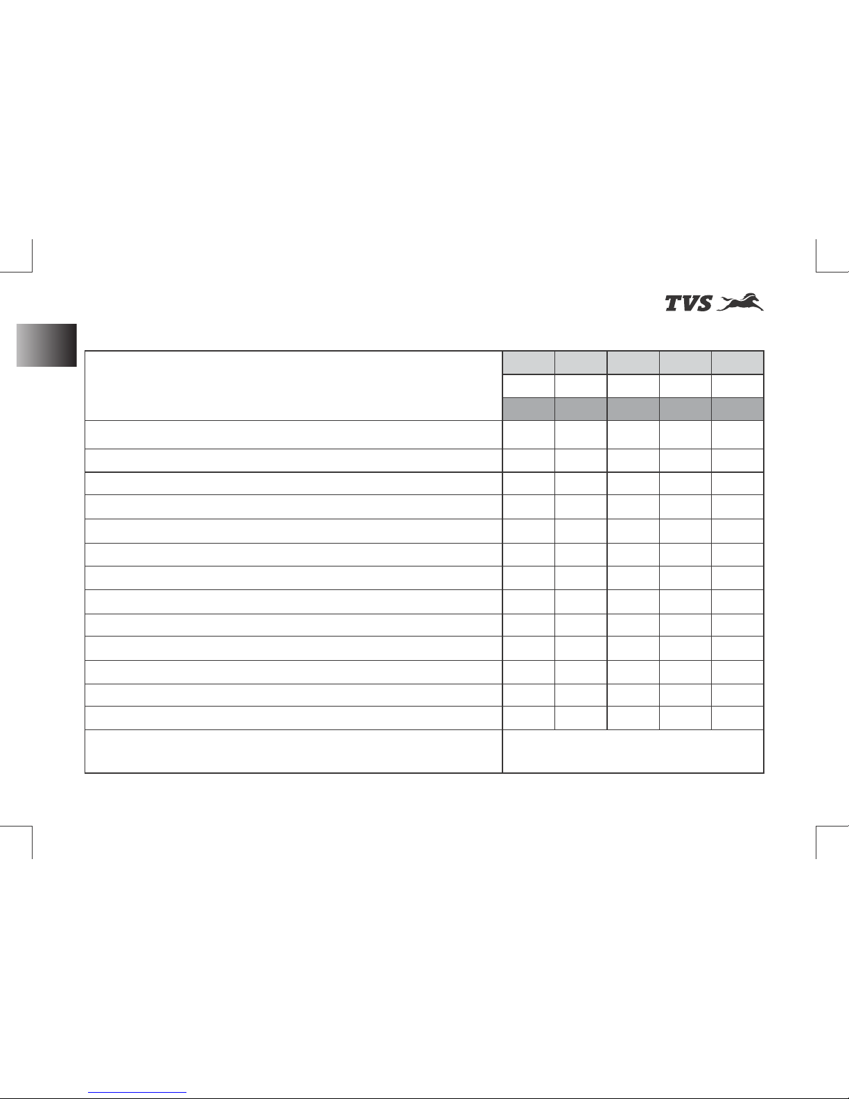
st
Revision:- Rev. 1, 1 Aug'2018 onwards
MAJOR MAINTENANCE
Planned Maintenance Schedule - To be performed by the Dealer
List of operations and type of intervals Service 1st 2nd 3rd 4th 5th
(km or month whichever of the two occurs early) Km x 1000 1 5 10 15 20
Months 2 6 12 18 24
Engine oil filter along with drain bolt washer R - R - R
Engine oil R T R T R
Air cleaner element - - R - R
Spark plug - - - - R
Tappet clearance (valve clearance)* - - I & A - I & A
Clutch operations (adjust if required) I & A I & A I & A I & A I & A
Throttle cable / grip / system (replace parts if required) - - I - I
Steering play I & A - I & A - I & A
Front and rear suspension - - I - I
Wheel bearing freeness (replace if required) - - I - I
Air suction system / engine breather - - I - I
Front fork oil replacement - - - - R
All fasteners I & TI - I & TI - I & TI
Drive chain slackness / lubrication Inspect, adjust and lubricate
every 500 km
* Adjust if necessary
70
Maintenance Schedule
Page 85
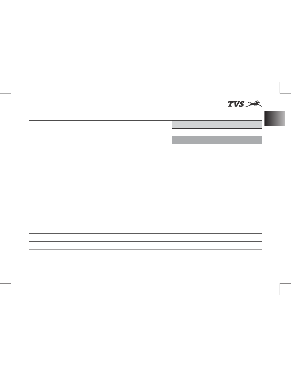
st
Revision:- Rev. 1, 1 Aug'2018 onwards
Planned Maintenance Schedule - To be performed by the Dealer
MAJOR MAINTENANCE
List of operations and type of intervals Service 1st 2nd 3rd 4th 5th
(km or month whichever of the two occurs early) Km x 1000 1 5 10 15 20
Months 2 6 12 18 24
Drive chain wear (replace if required) - - I - I
All lamps and horn - I I I I
Head lamp beam (focus) I & A I & A I & A I & A I & A
Battery voltage (recharge if required) I I I I I
Brake light switch operation I I I I I
Front and rear brake fluid level* I I R I R
Front and rear brake pad wear (replace if required) - I I I I
Disc plates (replace if required) - - I - I
Brake hose / rubber parts of master cylinder and
Caliper front and rear (replace if required) - - I - I
Master cylinder cups - - - - I & R
Tyre air pressure (at cold condition) I & A I & A I & A I & A I & A
Steering stem bearing (Inspect & lubricate with Grease if required) I & L - I & L - I & L
Speed sensor (free from any mud / clogging with dirt) I I I I I
* Replace brake fluid first at 10000 kms and every 20000 kms or 2 years thereafter.
71
Maintenance Schedule
Page 86
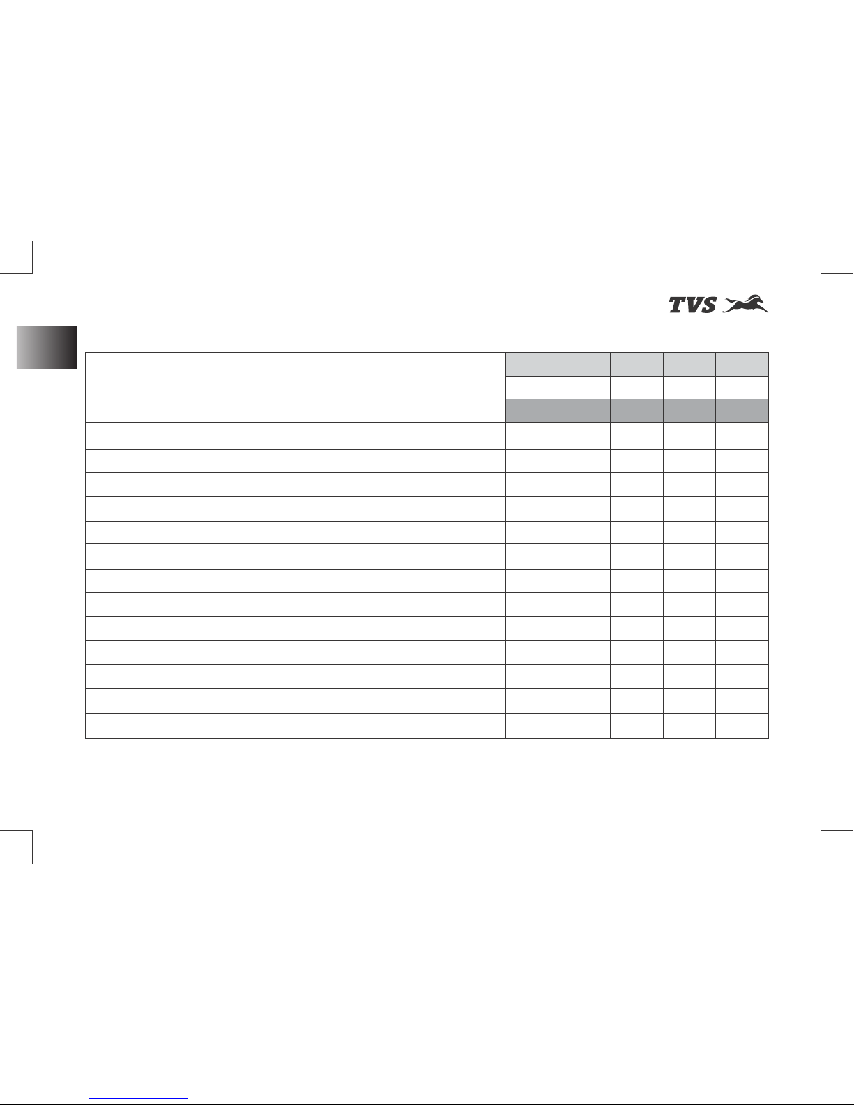
st
Revision:- Rev. 1, 1 Aug'2018 onwards
Planned Maintenance Schedule - To be performed by the Dealer
MAJOR MAINTENANCE
List of operations and type of intervals Service 1st 2nd 3rd 4th 5th
(km or month whichever of the two occurs early) Km x 1000 1 5 10 15 20
Months 2 6 12 18 24
Coolant level, water hoses and O-rings (replace if required)* I I I I I
Fuel hose / system I - I - I
Fuel filter - - - - R
Swing arm bearing (replace if required) I I I I I
Side stand C, I & L C, I & L C, I & L C, I & L C, I & L
Side stand switch function and physical damage I I I I I
Drive chain guide wear (replace if required) - - I - I
Instrument cluster MIL lamp function I I I I I
Radiator fan / fins and deflector (clean if required) I I I I I
Reading fault codes using diagnostic tool I I I I I
Availability of fuse puller and fuse condition I I I I I
Brake pedal / gear shift lever mounting pin (lubricate using grease) I I I I I
Ignition cum steering lock (lubricate using oil) I I I I I
* Coolant, hoses and O-rings must be replaced every 30000 kms or every 3 years.
At higher odometer readings, the above service intervals to be followed.
72
Maintenance Schedule
Page 87
st
Revision:- Rev. 1, 1 Aug'2018 onwards
MAJOR MAINTENANCE
w While working on batteries or fuel related
items care must be taken to avoid fire or
explosion. Use non-flammable solvent only.
Keep away the fire (like cigarettes, sparks
and flames etc.) from the battery and fuel
related items.
w Ensure to remove the head lamp fuse, to
avoid battery discharge during working.
Safety Precautions
Before you are starting any maintenance
repairs,
w Make sure that engine is in OFF condition.
This will help in eliminating several potential
hazards like:
- Poisoning from engine exhaust Carbon
Mon oxid e ( be sure t here is prope r
ventilation whenever engine is operated in
indoor).
- Let the engine and exhaust to cool before
working on the motorcycle to avoid burns
from hot parts.
- Do not run the engine without instruction
for doing the same to avoid injury from
moving parts.
w Carefully read the instruction before
starting, and ensure that you have tools and
skill required for doing the maintenance
service.
w Park the vehicle on a flat firm surface with
the side stand, centre stand (if available) or
the auxiliary stand (paddock stand refer
page 105) to prevent the motorcycle from
falling while doing the maintenance service.
Note
W e r e c o m m e n d t h a t t h e
maintenance jobs as p e r t h e pl a n n e d
maintenance schedule be performed by your
TVS Motor Company Authorised Main
Dealer. Trained service personals of the
Dealer can provide quality, reliable and
economical service to your vehicle.
Use only TVS Motor Company Limited
Genuine parts for long and reliable life of your
motorcycle.
73
Safety Precautions
Page 88
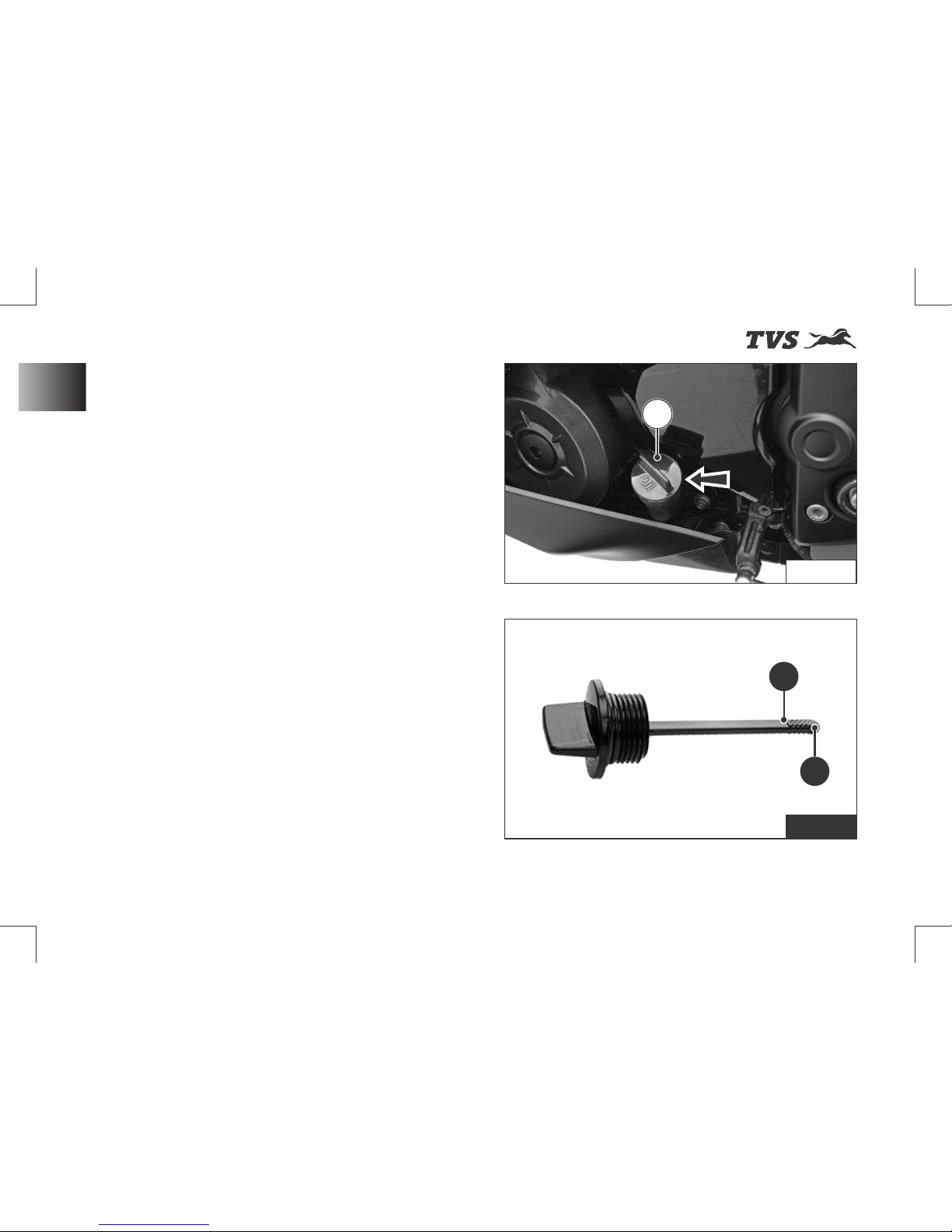
st
Revision:- Rev. 1, 1 Aug'2018 onwards
MAJOR MAINTENANCE
Engine Oil Level
Ensure the safety precautions listed in the page
73 are followed properly.
Check the engine oil level before riding the
motorcycle. Insufficient engine oil or too much
engine oil affects the engine adversely.
To check the engine oil level, a gauge oil level
(dip stick) (A) given on the left side of the
crankcase (ref. Fig. 38).
w Wipe off the surroundings of the gauge oil
level. Start the engine and let it idle for 3 to 5
minutes.
w Switch OFF of the ignition. Hold the vehicle
in upright condition with both the wheels on
ground, on a flat and firm surface.
w After 2 to 3 minutes, remove the gauge oil
level (A) and wipe it cleanly.
w Re-fix the gauge again. Slowly and steadily
remove the gauge and inspect the oil level.
w The level should be between minimum (1)
and maximum level (2) mark on the gauge
(ref. Fig. 39).
w If the level is below the minimum level (1),
slowly add recommended engine oil till the
level reaches to maximum level (2).
Fig. 38
Fig. 39
AA
2
1
74
Engine Oil Level
Page 89
st
Revision:- Rev. 1, 1 Aug'2018 onwards
MAJOR MAINTENANCE
Caution
Running the engine with
insufficient or excess engine oil may cause
serious damage to the engine.
For topping-up, always use TVS Motor
Company recommended engine oil only.
Hold the vehicle in upright condition with
both wheels on ground, on a flat and firm
surface while checking the oil level to avoid
wrong indication.
Engine oil and oil filter must be replaced by a
TVS Motor Company Authorised Main
Dealer at the intervals specified in the
planned maintenance schedule without fail.
Failing which disqualifies for warranty.
Warning
Correctly recycle or dispose
the used engi n e oil i n ord e r to avoid
environment pollution.
w Re-fix gauge after ensuring correct oil level.
w Wipe out the oil traces with a clean cloth to
prevent dust accumulation.
w Re-fix gauge after ensuring correct oil level.
w Wipe out the oil traces with a clean cloth to
prevent dust accumulation.
75
Engine Oil Level
Page 90
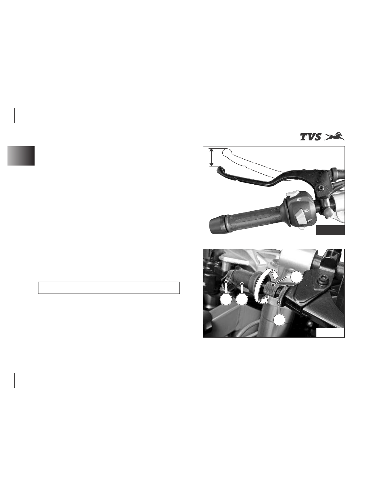
st
Revision:- Rev. 1, 1 Aug'2018 onwards
MAJOR MAINTENANCE
Clutch Free Play
Clutch Free Play
Ensure the safety precautions listed in the page
73 are followed properly.
Clutch free play adjustment may be required if
the motorcycle gets OFF while shifting from
neutral to gear or tends to creep; or if the clutch
slips (vehicle acceleration lags behind the
engine rpm).
Minor clutch free play adjustment can be done
by means of clutch cable adjuster at the clutch
lever end.
w Measure the clutch free play (A) at the lever
end as shown (ref. Fig 40).
- If the measured free play is ‘more’ or ‘less’
than the standard limit given below:
Clutch lever free play 8 to 12 mm
w Remove the cable clamp (1). Pull back the
dust cover (2) of clutch lever (ref. Fig. 41).
w Loosen the lock nut (3) and turn the adjuster
(4) ‘in’ or ‘out’ till the specified play is
obtained (ref. Fig. 41).
- After the adjustment, once again check
the free play and confirm.
Fig. 40
Fig. 41
A
3
4
76
1 2
Page 91
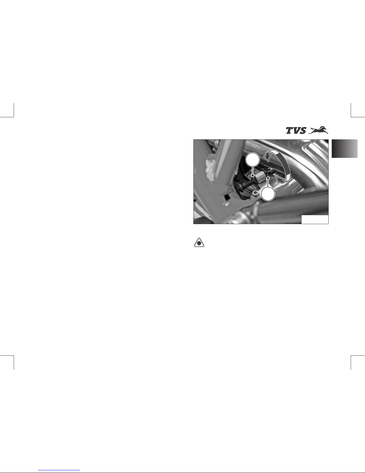
st
Revision:- Rev. 1, 1 Aug'2018 onwards
MAJOR MAINTENANCE
w Lock the lock nut (3) again.
- If the adjuster is threaded out to its
maximum limit or if the correct free play
can not be obtained using the cable
adjuster, loosen the lock nut and completely
turn-in the clutch cable adjuster.
w Re-fix the dust cover (2) and cable clamp
(1).
w Loosen the lock nut (5) at the bottom end of
the clutch cable (ref. Fig. 41).
w Turn the adjuster in (6) ‘in’ or ‘out’ until the
specified play is obtained and then tighten
the lock nut and check the adjustment once
again (ref. Fig. 42).
- After adjusting the clutch play, start the
engine and engage the gear. Ensure that
the engine is not stalling and not creeping.
- Gradually release the clutch lever while
slowly applying the throttle. The vehicle
should begin to move slowly and accelerate
smo ot hly. El se co nta ct TVS M ot or
Company Authorised Main Dealer.
Caution
Clutch play free play should
be checked and adjusted only when the
engine is cold.
During clutch play checking and adjustment,
check the clutch cable for kinks or sign of
wear that could cause stickiness or failure.
Lubricate the clutch cable using a cable
lubricant available in the market to prevent
premature failure and corrosion.
5
6
Fig. 42
77
Clutch Free Play
Page 92
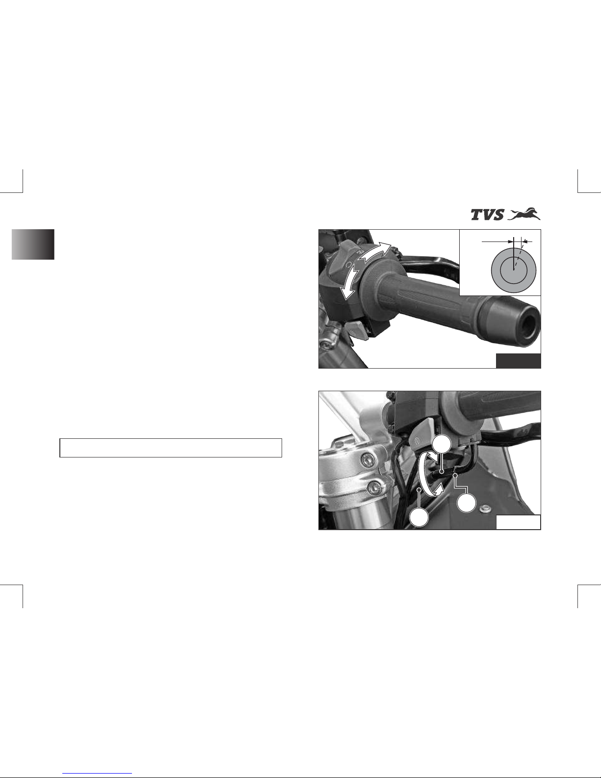
st
Revision:- Rev. 1, 1 Aug'2018 onwards
MAJOR MAINTENANCE
Throttle Cable Play
Throttle Cable Play
Ensure the safety precautions listed in the page
73 are followed properly.
w Check and ensure the smooth rotation of
throttle grip from fully open to fully closed
cond i tion at b o th e x treme steerin g
positions (left and right).
w Check for the proper routing of cable and it
is not fouling with any part during steering
operation.
w Ensure that the engine is in cold condition.
w Measure the throttle cable play at the
throttle grip end as shown in the figure at
various position of the steering (ref. Fig. 43).
Throttle cable play 3 to 7 mm
If the play is not within the specification,
w Slide the boot throttle adjuster (1) and then
loosen the lock nut (2) (ref. Fig. 44).
w Turn the throttle cable adjuster (3) ‘in’ or
‘out’ until the specified play is obtained
(ref. Fig. 44).
Fig. 43
3 to 7 mm
Fig. 44
3
1
2
78
Page 93
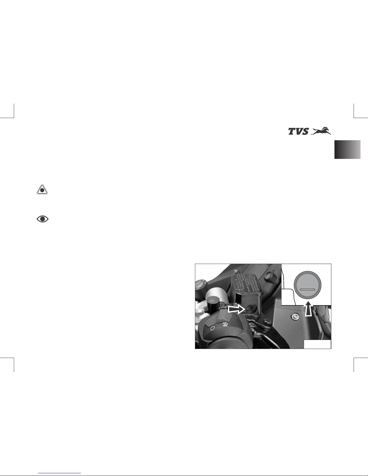
st
Revision:- Rev. 1, 1 Aug'2018 onwards
MAJOR MAINTENANCE
w After the adjustment, once again re-check
and ensure the right play.
w Tighten the locknut and re-locate the
throttle adjuster boot carefully.
Caution
Do not lubricate the throttle
cable, replace if found sticky or damaged.
Note
Replace the throttle cable if the
adjuster has reached its limit or if you observe
any sticky operation or damage.
Brake Fluid Level
Brake fluid level should not fall below the MIN
level mark on both front and rear brake fluid
reservoir. If the level drops below the limit, air can
get into the circuit and make the system
ineffective.
Brake fluid must be topped up and changed at
the intervals specified in planned maintenance
schedule without fail for the proper working and
to ensure the safety of the rider.
w Switch OFF and place the vehicle upright
on a flat and firm surface using centre stand
(if available) or on a auxiliary stand (paddock
stand ref. page 105).
Fig. 45
MIN
79
Brake Fluid Level
Page 94
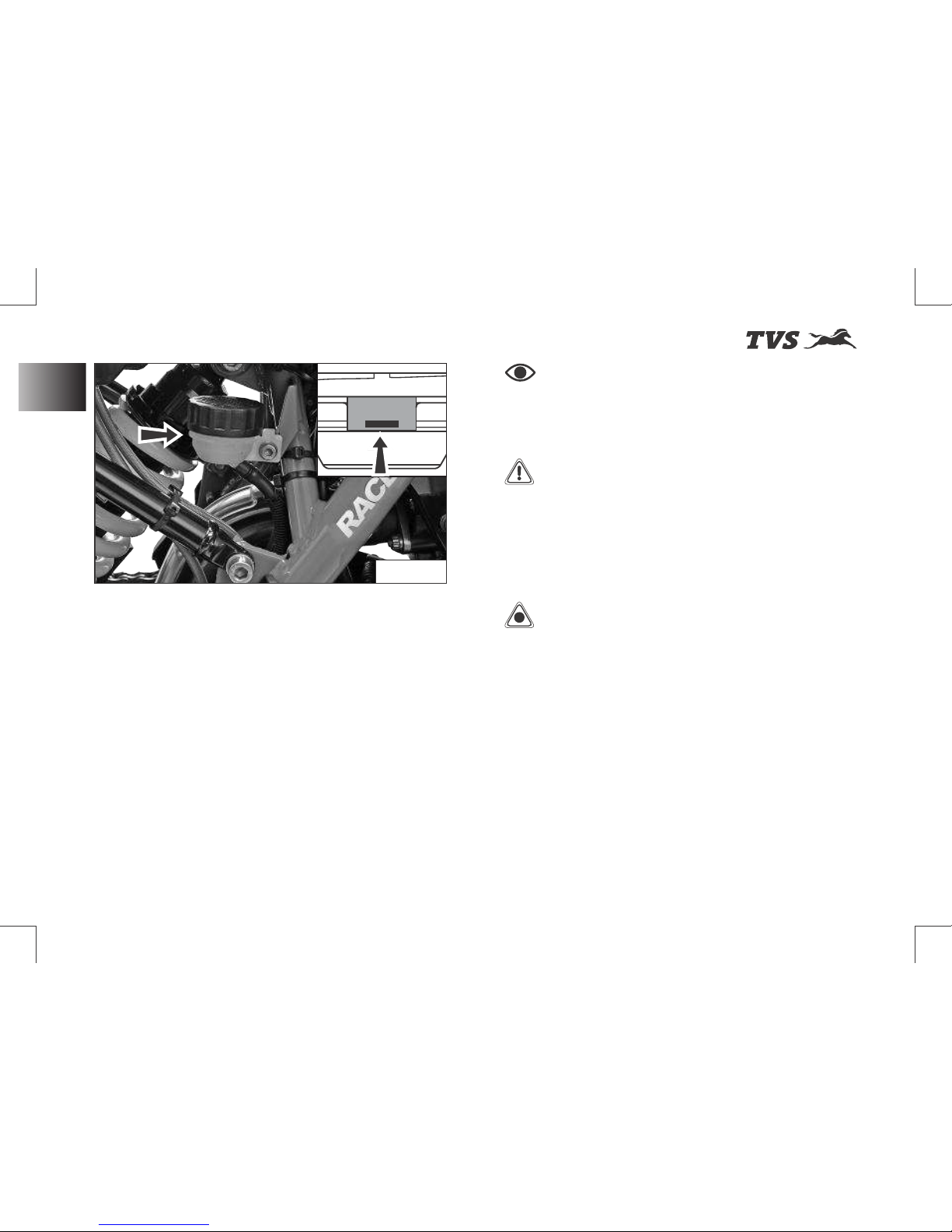
st
Revision:- Rev. 1, 1 Aug'2018 onwards
MAJOR MAINTENANCE
w Keep the handle bar straight.
w Inspect the oil level of both front and rear
brake fluid reservoirs (ref. Fig. 45 & Fig. 46).
w If the level is lower than the MIN level mark in
any of the reservoir, contact TVS Motor
Company Authorised Main Dealer for
topping up.
w If you find excessive play (sponginess) in the
front brake lever or in the rear brake pedal,
but both the brake pads are still in good
condition, contact TVS Motor Company
Authorised Main Dealer for the inspection
of system and to do the air bleeding.
Caution
Inspect for any leakage of
fluid in the brake circuit.
Cover the body parts with a protective cover
before topping up the brake fluid to prevent
the painted parts from getting damaged.
Incase of any fluid dripping on body panels, it
is recommended to be cleaned immediately.
Use only BASF (DOT 4) brake fluid from a
sealed container or drain the existing brake
fluid completely from the circuit and use
another brand (DOT 4) brake fluid to avoid mix
up with existing old and different brand fluid.
Note
Check the brake fluid level only
when the handle bar and vehicle is in straight
condition.
Warning
Lack of maintenance of the
brake system increases the risk of accident. If
you notice any malfunction in the brake
system contact nearest TVS Motor Company
Authorised Main Dealer for further diagnosis.
Fig. 46
MIN
80
Brake Fluid Level
Page 95
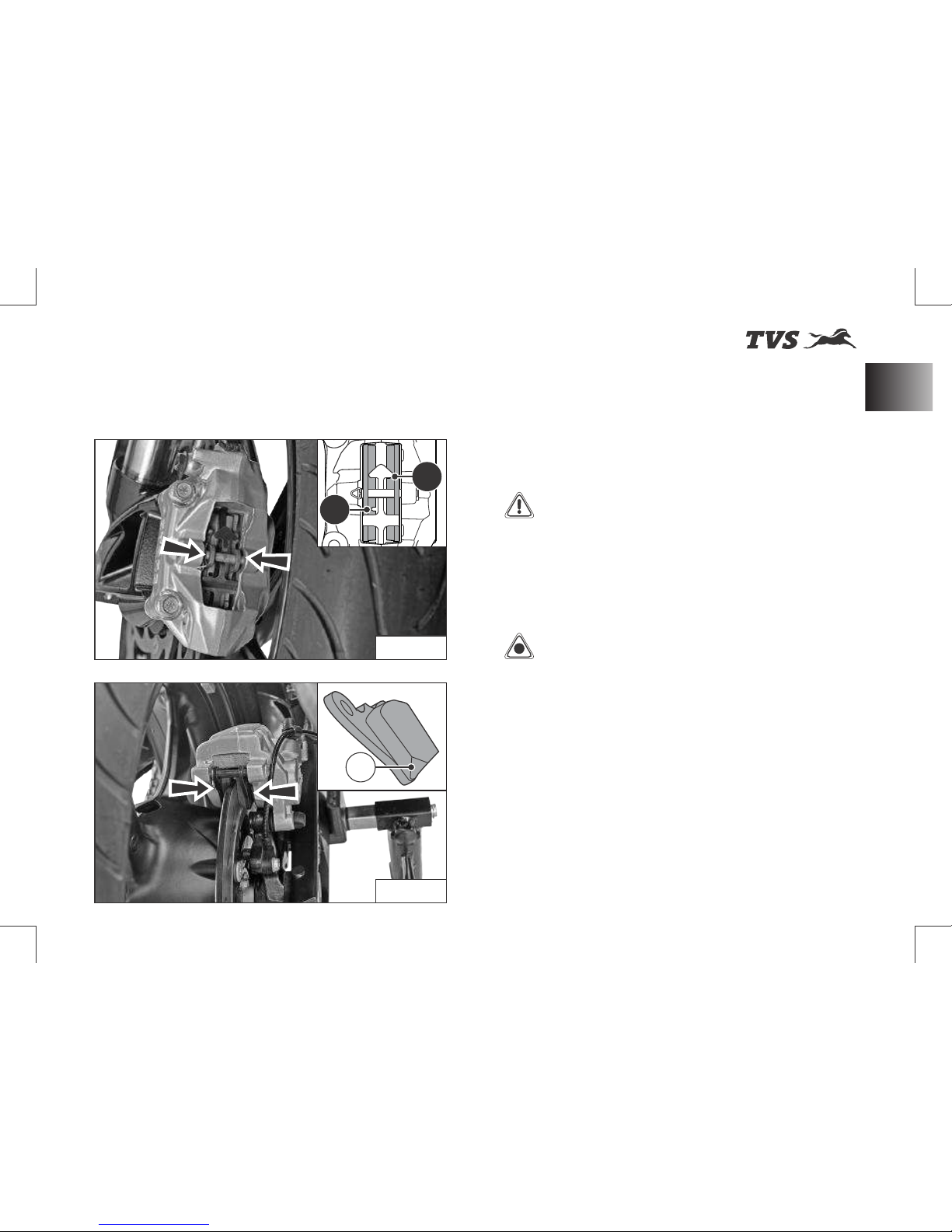
st
Revision:- Rev. 1, 1 Aug'2018 onwards
MAJOR MAINTENANCE
Brake Pad Wear
w Visually inspect both front brake pads wear
and rear brake pads wear.
- If the wear is found beyond the wear
indicator (A & B) groove as shown in the
figure in any one of the pad, replace brake
pads as a set with a new one. (ref. Fig. 47
& 48)
Warning
If the brake pads are used
beyond this groove, leads to metal support
contact with the brake disc and affects the
braking efficiency, disc integrity and leads to
unsafe riding conditions to the rider.
Caution
Replace the brake pads as a
set, if the wear indicator shows beyond the
wear limit.
Fig. 47
Fig. 48
B
A
A
81
Brake Pad Wear
Page 96
st
Revision:- Rev. 1, 1 Aug'2018 onwards
MAJOR MAINTENANCE
Rims & Tyres
Warning
The tyre inflation pressure in
cold condition is extremely important for the
performance and the safety of the rider.
Improper tyre pressure may result in: stability
and handling issues, wobbling, hard steering,
bumpy ride, uneven tyre wear etc.
When minor puncture occurs, tubeless tyres
take a long time to deflate, as they tend to
hold the air inside. If the tyres is found with
low pressure, check the tyres for puncture.
Check and adjust the tyres pressure only
when the tyres are cold.
Be sure to tighten the valve dust caps
securely to prevent leaks while riding.
82
Page 97
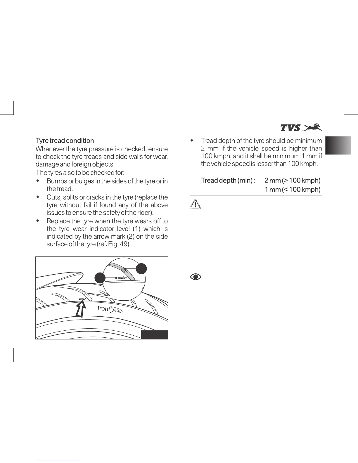
st
Revision:- Rev. 1, 1 Aug'2018 onwards
MAJOR MAINTENANCE
Rims & Tyres
Warning
Visually inspect the tyres at
regular in t e rvals for c rack s and cu ts,
especially on the side walls, and bulges or
large stains that indicate internal damage.
Replace them if damaged.
Remove any stones or other foreign bodies
stuck in the tread.
Note
Tread wear marks are integrated
into the main grooves on every tyre. If the tyre
tread has worn down to the level of the marks,
the tyre is completely worn. The location of
the tread wear marks are indicated by an aero
mark on the edge of the tyre (ref. Fig. 49).
Replace the tyre when the minimum tread
depth is reached.
1
2
Fig. 49
83
Page 98
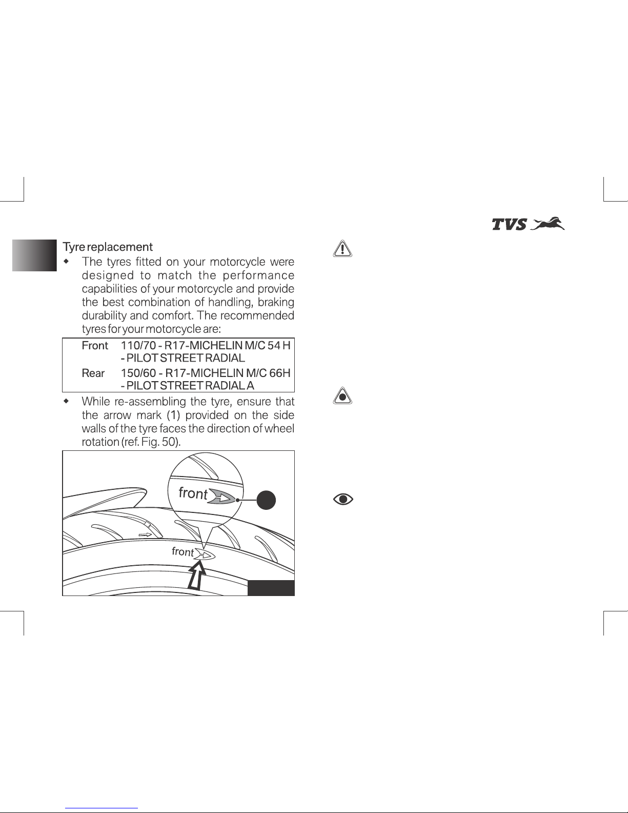
st
Revision:- Rev. 1, 1 Aug'2018 onwards
Fig. 50
MAJOR MAINTENANCE
Warning
Have the tyres replaced at
only TVS Motor Company Authorised Main
Dealer. Proper removal and reassembly of
wheels and the tyres are essential.
Use only the recommended tyre. Use of a tyre
other than the standard will cause instability.
Be sure the wheel is balanced after the new
tyre is installed.
Caution
Side walls of the tubeless
tyres which are in contact with the wheel rim
are only seals the air inside the wheel
assembly. Hence, care should be taken not to
damage the side walls of the wheel rim during
removal and reassembly of the tyres.
Note
Wheel balancing to be done
every 1 year or every 10000 km. In addition,
a f te r e v e r y t yre pu n c t u re re p a ir or
replacement, wheel balancing to be done
without fail. Do not remove or alter the
position of wheel balancing weights after the
completion of wheel balancing.
1
84
Rims & Tyres
Page 99
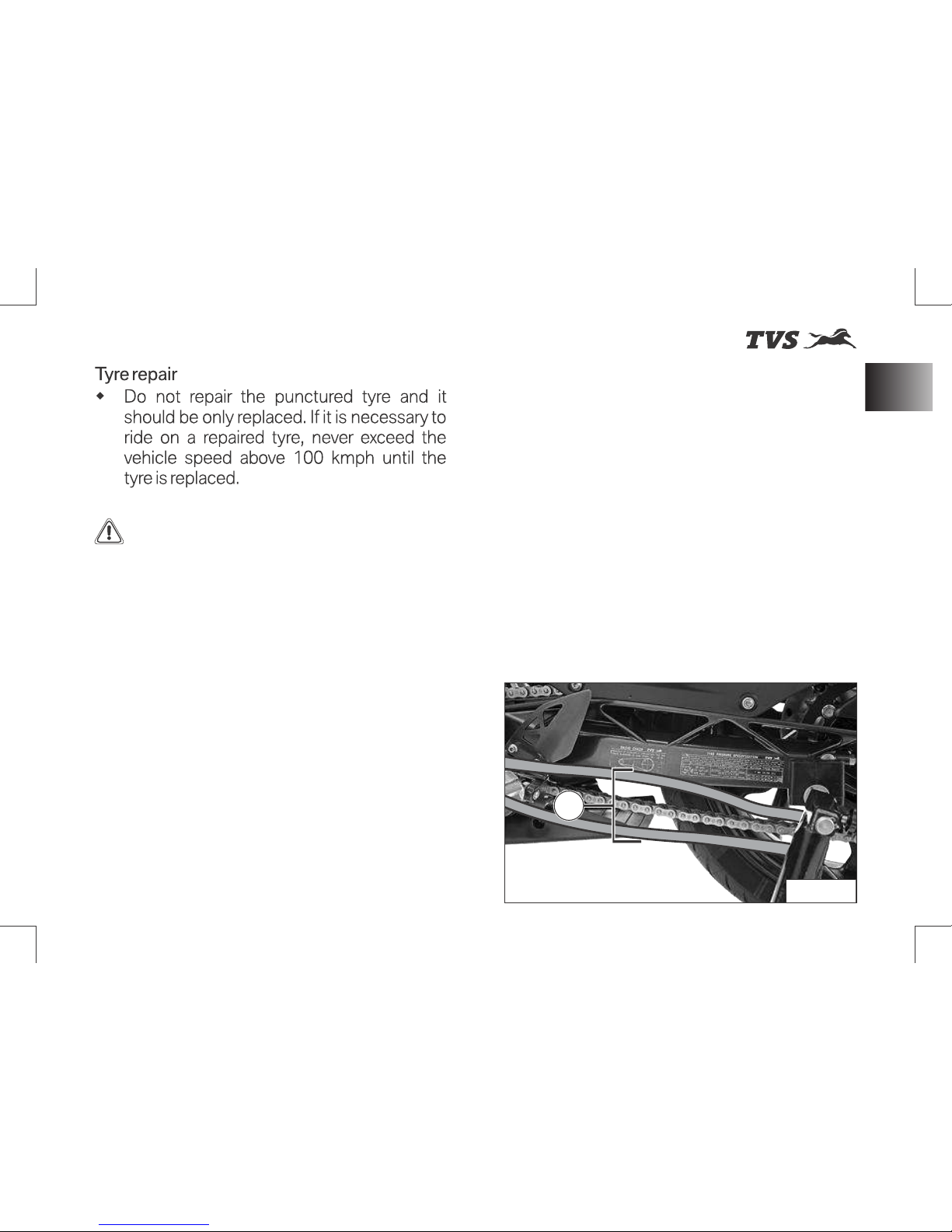
st
Revision:- Rev. 1, 1 Aug'2018 onwards
MAJOR MAINTENANCE
Drive Chain
Warning
Do not repair the punctured
tyre. It should not be replaced. If it is
necessary to run the vehicle on a repaired
tyre, never exceed 100 kmph speed until the
tyre is replaced.
Never install a tube inside a tubeless tyre on
this motorcycle. The tube may get burst
during ride due to excessive heat buildup
which will result in serious consequences.
Since the rims of this motorcycle is designed
for tubeless tyres, use tubeless tyres only.
During hard acceleration or braking, a tube
tyre could slip on the rim and deflate rapidly.
Drive Chain
Ensure the safety precautions listed in the page
73 are followed properly.
The drive chain’s service life is purely depended
upon the proper lubrication and adjustment.
Poor maintenance of drive chain can cause
premature wear or damage to the drive chain
and sprockets.
The drive chain must be inspected, cleaned,
adjusted and lubricated as per the planned
maintenance schedule. Under severe usage, or
when the motorcycle is used more dusty or
muddy areas, more frequent maintenance is
necessary.
Fig. 51
85
A
Page 100
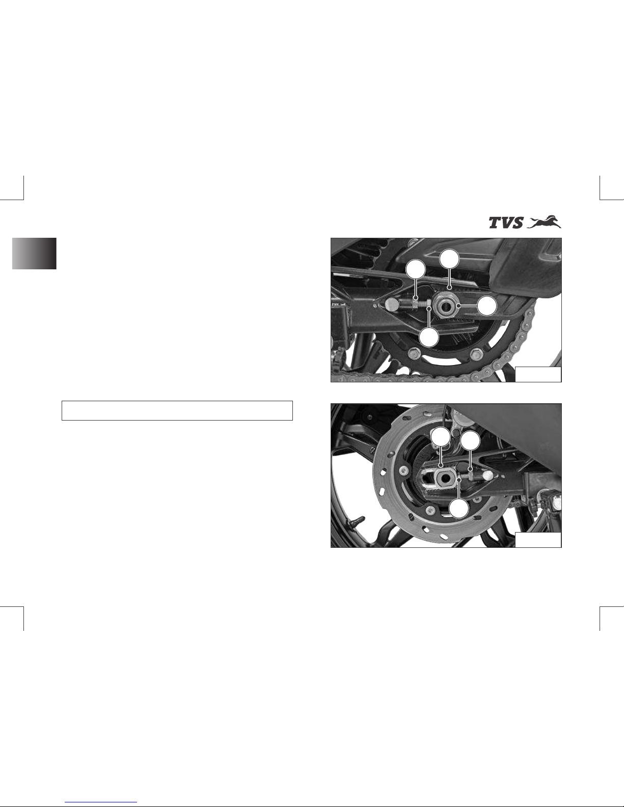
st
Revision:- Rev. 1, 1 Aug'2018 onwards
MAJOR MAINTENANCE
Drive Chain
Slackness inspection
w Ensure the engine is turned OFF and the
vehicle is in neutral.
w Place the motorcycle on its centre stand (if
available) or side stand or in auxiliary stand
(paddock stand ref. page 105).
w Using the fingers, check the slackness of
the chain at the lower portion, midway (A)
between the sprockets (ref. Fig. 51).
w The slackness (A) should be between 30 to
40 mm at the various points of the chain.
Drive chain slackness 30 to 40 mm
w The chain should be adjusted at the point of
least deflection.
Adjustment
w Place the vehicle on centre stand (if
applicable) or side stand or auxiliary stand
(paddock stand) on a flat firm surface.
w Loosen the rear axle nut (1) using a proper
spanner from the tool kit (ref. Fig. 52).
w Release the lock nuts (2 & 3) (ref. Fig. 52 &
53) using proper spanner from the tool kit
(ref. page 103).
Fig. 52
2
6
4
5
1
3
7
Fig. 53
86
 Loading...