

TV One C2-7300, C2-7100, C2-7110, C2-7200, C2-7210 Operation Manual
...
C2-7000 SERIES OPERATION MANUAL
C2-7000 Series
Dual Channel
Video Processor
Operation Manual
Version 2.9
1

C2-7000 SERIES OPERATION MANUAL
C2-7000 Series
Dual Channel
Video Processor
Operation Manual
Version 2.9

C2-7000 SERIES OPERATION MANUAL
Table of Contents
1.0 DISCLAIMER............................................................................................. 1
1.1 Regulatory Agency Acceptance...........................................................................1
1.2 FCC Statement....................................................................................................2
2.0 IMPORTANT SAFETY INSTRUCTIONS...................................................3
3.0 CAPABILITY, TERMS OF REFERENCE AND OVERVIEW SUMMARY 13
3.1 Device Capabilities............................................................................................13
3.2 Terms of Reference...........................................................................................14
3.3 Device Overview................................................................................................15
3.4 Models available................................................................................................16
3.5 Input Sources ....................................................................................................17
3.6 Outputs..............................................................................................................17
3.7 Windows............................................................................................................17
3.8 Layers................................................................................................................18
3.9 Modes................................................................................................................19
3.9.1 Switcher Mode...................................................................................................19
3.9.2 Independent Mode.............................................................................................20
3.9.3 Dual PIP Mode ..................................................................................................21
4.0 UNPACKING AND INSTALLATION ........................................................22
4.1 Shipping Carton.................................................................................................22
4.2 Furnished Accessories ......................................................................................22
5.0 FUNCTIONAL CHECK............................................................................23
5.1 Important Safety Instructions .............................................................................23
5.2 Factory Reset....................................................................................................24
5.3 Initial Operation Check Using Factory Default Settings......................................24
6.0 CONTROLS AND CONNECTIONS.........................................................26
6.1 10-button programmable panel..........................................................................26
6.2 48-button non-programmable panel...................................................................28
6.3 Inputs and Outputs ............................................................................................30
7.0 AUDIO INPUTS AND OUTPUTS.............................................................32
7.1 Connection summary.........................................................................................32
7.2 DARS locking ....................................................................................................32
7.3 Audio outputs in different modes........................................................................33
7.4 Options available...............................................................................................33
8.0 CHANGING THE OPERATING MODE ...................................................35
8.1 Operating the Unit as a Video Switcher .............................................................35

C2-7000 SERIES OPERATION MANUAL
8.1.1 Switching an Input .............................................................................................36
8.2 Operating the Unit as two Independent processors............................................36
8.2.1 Selecting Inputs to the Windows........................................................................36
8.3 Operating the Unit in Picture In Picture Mode (Dual PIP)...................................37
8.3.1 Selecting Inputs for the Individual Windows.......................................................37
9.0 MENU TOPOGRAPHY AND ADJUSTMENT METHODOLOGY.............39
9.1 The High Level Menu Structure.........................................................................40
9.2 Advanced menus...............................................................................................41
9.3 Group Names and Descriptions.........................................................................41
9.4 Items Associated with the Device mode group...................................................41
9.5 Items Associated with the Adjust outputs group.................................................41
9.6 Items Associated with the Adjust windows group...............................................45
9.6.1 Extended scaling controls..................................................................................49
9.6.2 ‘Aspect adjust’ = ‘Advanced’..............................................................................50
9.6.3 ‘Aspect adjust’ = ‘Pixel’......................................................................................51
9.7 Items Associated with the Adjust keyers group..................................................51
9.8 Edge Blend items within the Adjust keyers group ..............................................53
9.9 Items Associated with the Adjust logos group....................................................54
9.10 Items Associated with the Adjust borders group ................................................55
9.11 Items Associated with the Adjust sources group................................................56
9.11.1 Menu items common to all inputs.......................................................................57
9.11.2 DVI Source Menu Items.....................................................................................60
9.11.3 RGB Source Menu Items...................................................................................62
9.11.4 CV & YC Source Menu Items ............................................................................63
9.11.5 Still Image Store / Testcard Source Menu Items................................................63
9.12 Items Associated with the Adjust audio group + other digital audio
adjustments...................................................................................................................64
9.12.1 Extra item in Adjust outputs...............................................................................66
9.12.2 Extra item in Adjust windows.............................................................................66
9.12.3 Extra item in Adjust sources ..............................................................................67
9.12.4 Adjust audio.......................................................................................................67
9.13 Items associated with the Adjust transitions group.............................................68
9.14 Items Associated with the Adjust buttons group.................................................69
9.15 Items associated with the Adjust ethernet group................................................70
9.16 Items associated with the Adjust resolutions group............................................72
9.17 Items Associated with the System group ...........................................................75
10.0 SERIAL PORT.........................................................................................79

C2-7000 SERIES OPERATION MANUAL
10.1 Connection........................................................................................................79
10.2 Communications protocol..................................................................................79
11.0 SERIAL / IP CONTROL SPECIFICATION...............................................81
11.1 Communication protocol basics.........................................................................81
11.2 Packet format....................................................................................................82
11.3 Function list.......................................................................................................84
11.4 Examples...........................................................................................................92
11.5 Reading and writing macros ..............................................................................93
11.5.1 Reading a previously stored Macro....................................................................94
11.5.2 Writing to a macro..............................................................................................94
11.5.3 Run and Restore macros...................................................................................95
11.5.4 Emulate a front panel button press....................................................................95
11.5.5 Reset command ..............................................................................................100
12.0 COMMON OPERATIONS......................................................................101
12.1 Operation of the Keyer.....................................................................................101
12.2 Creating a Macro.............................................................................................106
12.3 Standards Conversion – NTSC to PAL............................................................107
13.0 EDGE-BLENDING SETUP....................................................................108
13.1 Introduction......................................................................................................108
13.2 Edge-blending requirements............................................................................109
13.3 Basic setup of the two projectors.....................................................................110
13.4 Connections to the scaler(s) and projectors.....................................................110
13.5 Initial setup......................................................................................................111
13.6 Edge-blending activation..................................................................................112
13.7 Edge-blending overlap / size............................................................................112
13.8 Edge-blending guide lines................................................................................113
13.9 Alignment of projectors....................................................................................114
13.10 Gamma correction...........................................................................................116
13.11 Brightness compensation.................................................................................116
13.12 Aspect ratio adjustment...................................................................................117
13.13 Locking both outputs together..........................................................................117
13.14 Other setup approaches..................................................................................118
14.0 WINDOWS CONTROL PANEL ............................................................. 120
14.1 Opening screens .............................................................................................120
14.1.1 Selecting a serial port connection....................................................................120
14.1.2 Selecting an Ethernet connection....................................................................120
14.2 Connecting to a unit.........................................................................................121

C2-7000 SERIES OPERATION MANUAL
14.3 Application menu’s...........................................................................................123
14.3.1 File menu.........................................................................................................123
14.3.2 Communications menu....................................................................................123
14.3.3 Tools menu......................................................................................................124
14.3.4 Resolution menu..............................................................................................124
14.4 Scripting tool....................................................................................................124
14.5 Image Loader..................................................................................................125
14.5.1 Loading Still Images / Testcards......................................................................126
14.5.2 Loading Logos.................................................................................................127
14.5.3 Maximum Image size – how large can my Logo / Still Image / Testcard be?....128
14.6 Resolution Editor.............................................................................................128
15.0 TROUBLESHOOTING AND TECHNICAL SUPPORT...........................132
15.1 There is no picture on the Output.....................................................................132
15.2 The image is shifted and not fully viewable......................................................132
15.3 The output resolutions no longer appear as expected......................................132
15.4 There is excessive flicker on the Output..........................................................133
15.5 The Output image is distorted..........................................................................133
15.6 Some colors appear to be incorrect on the CV/YC output................................133
15.7 How can I reduce color smearing on CV connections?....................................133
15.8 I can no longer adjust the Output image resolution..........................................133
15.9 The picture on the video display is black and white..........................................133
15.10 The picture on the video display is green.........................................................133
15.11 The RGB input is selected but the image is rolling or pink. ..............................134
15.12 The video signal from my DVD player does not appear to work.......................134
15.13 Image is flashing, snow is present, or source image doesnot appear..............134
16.0 RETURN PROCEDURE........................................................................135
16.1 Are you sure there's a fault?............................................................................135
16.2 To return a unit for repair.................................................................................135
17.0 WARRANTY POLICY............................................................................137
18.0 CONNECTOR PINOUTS.......................................................................138
18.1 DVI-I connector................................................................................................138
18.2 RS232 / DB9 connector...................................................................................138
18.3 4 Pin mini-DIN S-video connector (YC) input...................................................138
19.0 SPECIFICATION ...................................................................................139
19.1 Video Inputs.....................................................................................................139
19.2 Genlock Input..................................................................................................139
19.3 Independent Output 1......................................................................................139

C2-7000 SERIES OPERATION MANUAL
19.4 Independent Output 2......................................................................................139
19.5 Input/Output Range .........................................................................................139
19.6 Input RGB Sync...............................................................................................140
19.7 Output RGB Sync............................................................................................140
19.8 SDI/HD-SDI Embedded Audio & Ancillary Data (C2-7200/7210/7260 only).....140
19.9 SDI/HD-SDI Embedded Audio (C2-7300, C2-7310 only) .................................140
19.10 AES3-id inputs & outputs(C2-7300, C2-7310 only)..........................................140
19.11 Audio Switching (Optional A2-2000) ................................................................140
19.12 Control Methods..............................................................................................140
19.13 Mechanical......................................................................................................141
19.14 Environmental..................................................................................................141
20.0 CONTACT INFORMATION...................................................................142

1.0 DISCLAIMER
This product is intended for professional and/or home use. This product is not
intended for use in a medical environment and does not have the required
certifications for such use. Similarly, use aboard any aircraft or spacecraft
while in flight or as an adjunct to any surface, airborne or marine navigation
system or any offshore marine activity, including control of any watercraft, or
any use similar to those specifically herein mentioned is prohibited. Use in the
aforementioned circumstances would require additional testing and
certification.
You have not become the owner of any software - you have merely
purchased the right to use the software. You may make one copy of the
software for your own use. Other copies will be deemed a breach of copyright.
No warranty is made either expressed or implied including but not limited to
any implied warranties of merchantability or fitness for a particular purpose. In
no event shall the supplier or manufacturer of this product be liable for errors
found within, or be liable for any direct, indirect or consequential damages or
loss in connection with the purchase or use of this hardware software or
manual. The sole and exclusive liability to the supplier and manufacturer
regardless of the form of action shall not exceed the replacement cost of the
materials described herein.
By using this equipment you have indicated that you have agreed to the terms
listed above. If you do not wish to agree or the above terms are contrary to
your conditions of purchase you may return the equipment, unused, to your
supplier. All trademarks and copyrights are acknowledged. E&OE.
1.1 Regulatory Agency Acceptance
European ‘CE’ Mark Statement
C2-7100, C2-7110, C2-7200, C2-7210, C2-7260:
Emissions: BS EN 50081-1 (Generic Emission Standard for Residential,
Commercial and Light Industrial)
Immunity: BS EN 50082-1 (Generic Immunity Standard for Residential,
Commercial and Light Industrial)
Safety Directive: BS EN 60065:2002 (Audio/Visual Equipment Safety)
C2-7300, C2-7310:
Emissions: BS EN 55031-1 (Emission: Audio, video, audio-visual and
entertainment lighting control apparatus for professional use)
Immunity: BS EN 55031-2 (Immunity: audio, video, audio-visual and
entertainment lighting control apparatus for professional use)
Safety Directive: BS EN 60065:2002 (Audio/Visual Equipment Safety)
1

1.2 FCC Statement
Class A Device: This equipment has been tested and found to comply with
the limits for a Class A digital device pursuant to Part 15 of the FCC Rules.
These limits are designed to provide a reasonable protection against harmful
interference when the equipment is operated in a commercial environment.
This equipment generates, uses and can radiate radio frequency energy and,
if not installed and used in accordance with the Instruction Manual, may cause
harmful interference to radio communications. Operation of this equipment in
a residential area is likely to cause harmful interference in which case the user
will be required to correct the interference at his own expense.
Caution: This equipment is intended for use in the manner prescribed in the
Instruction Manual. Any user changes or modifications not expressly
approved by TV One Multimedia Solutions could void the user’s authority to
operate the equipment. Connecting this equipment to external devices
requires no specially shielded cabling for FCC compliance. The Instruction
Manual shows or describes the proper connection of this equipment for
operation that insures FCC compliance.
Direct all inquiries regarding FCC compliance to:
TV One Multimedia Solutions
1350 Jamike Drive
Erlanger, KY 41018
859.282.7303
859.282.8225 (Fax)
Manual Version Information
Version: 2.9
Release Date: November, 2009
Manual Copyright Notice
This Operation Manual is the intellectual property of TV One, ©2007-2008. No
portion of this manual may be copied or reproduced in any manner or by any
means, including, but not limited to electronic and electro-mechanical, without
the express written permission of TV One.
2

2.0 IMPORTANT SAFETY INSTRUCTIONS
To insure the best from this product, please read this manual carefully. Keep
it in a safe place for future reference.
To reduce the risk of electric shock, do not remove the cover from the unit.
No user serviceable parts inside. Refer servicing to qualified personnel.
2.1 Power and connections
This unit must be connected to a mains socket outlet with a protective earth
connection.
This unit is not disconnected from the AC power source as long as it is
connected to the wall outlet. The off state for this unit is called standby mode.
In standby mode the unit is designed to consume a reduced quantity of power
compared to normal operating modes.
When not using the unit for a long period of time, insure that the AC power
cord is disconnected from the wall outlet.
The AC wall outlet should be installed near to the unit and be easily
accessible.
Do not plug in or attempt to operate an obviously damaged unit.
2.2 Water and moisture
To reduce the risk of fire and personal injury, operation of this device outdoors
and/or exposure to rain, water or excessive moisture is expressly prohibited.
The apparatus shall not be exposed to dripping or splashing and no objects
filled with liquids, such as vases, shall be placed on the apparatus.
2.3 General care
Do not force switches or external connections.
When moving the unit, disconnect the serial port connections first then the
power cable and finally the interconnecting cables to other devices.
Do not attempt to clean the unit with chemical solvents or aerosol cleaners, as
this may damage the unit. Use a clean dry cloth.
2.4 Location
Installation of this unit should be in a cool dry place, away from sources of
excessive heat, vibration, dust, moisture and cold.
3

2.5 Ventilation
Slots and openings in the sides of the unit are provided for ventilation. To
ensure reliable operation, avoid obstruction of these openings and ensure the
unit is installed in a well-ventilated area.
2.6 Intellectual property
Some IC chips in this product include confidential and/or trade secret
property. Therefore you may not copy, modify, adapt, translate, distribute,
reverse engineer, reverse assemble or decompile the contents thereof.
4

2.0 IMPORTANT: CONSIGNES DE SECURITE
Afin de tirer le meilleur de ce produit, merci de lire attentivement ce manuel.
Gardez-le dans un endroit sûr pour pouvoir le consulter à nouveau.
Afin de réduire le risque de choc électrique, ne retirez pas l’unité de sa
protection.
Aucune pièce réparable par l’utilisateur à l’intérieur. Référez-vous à des
personnes qualifiées.
2.1 Alimentation électrique et connexions
Il faut brancher l'appareil sur une prise du secteur disposant d'une mise à la
terre.
Cette unité n’est pas déconnectée de la source de courant électrique tant
qu’elle est connectée à la prise murale. Le mode éteint de cette unité est
appelé mode de veille. En mode de veille, cette unité est conçue pour
consommer une quantité réduite de courant par rapport aux modes normaux
d’utilisation.
Lorsque vous n’utilisez pas l’unité pendant une longue période, assurez-vous
que le câble d’alimentation électrique est déconnecté de la prise murale.
La prise murale de courant doit être installée près de l’unité et aisément
accessible.
Ne branchez pas et n’essayez pas d’utiliser une unité visiblement
endommagée.
2.2 Eau et humidité
Pour réduire les risques d’incendie et de dommages corporels, l’utilisation de
cet appareil à l’extérieur et/ou son exposition à la pluie, l’eau ou une humidité
excessive est expressément interdite.
L’appareil ne doit pas être exposé aux gouttes ou aux éclaboussures et aucun
objet contenant de l’eau, comme par exemple un vase, ne doit être posé sur
l’appareil.
5

2.3 Entretien général
Ne forcez pas les boutons ou connexions externes.
Lorsque vous déplacez l’unité, déconnectez d’abord les connexions de ports
en série puis le câble d’alimentation et enfin les câbles de connexion avec
d’autres appareils.
N’essayez pas de nettoyer l’unité avec des dissolvants chimiques ou des
produits nettoyants en aérosol, car cela peut endommager l’unité. Utilisez un
chiffon propre et sec.
2.4 Emplacement
L’installation de cette unité doit se faire dans un endroit frais et sec, éloigné
de sources excessives de chaleur, de vibrations, de poussière, d’humidité et
de froid.
2.5 Aération
Les rainures et les ouvertures sur les cotés de l’unité servent à l’aérer. Pour
permettre une utilisation sûre, évitez d’obstruer ces ouvertures et assurezvous que l’unité est installée dans un endroit bien aéré.
2.6 Propriété intellectuelle
Certaines puces IC dans ce produit contiennent des éléments propriétaires
confidentiels et/ou des secrets commerciaux. Vous ne devez donc pas copier,
modifier, adapter, traduire, distribuer, démonter, désassembler, ou
décomposer leur contenu.
6

2.0 INSTRUCCIONES IMPORTANTES DE SEGURIDAD
Para sacar el mejor provecho de este producto, léase este manual con
detenimiento. Guárdelo en un lugar seguro para poder hacerle referencia en
el futuro.
Para reducir el riesgo de calambre, no quite la cubierta del aparato.
No hay piezas utilizables dentro. Remítase todo mantenimiento a personal
cualificado.
2.1 Corriente y conexiones
Esta unidad debe estar conectada a una toma de corriente eléctrica con una
conexión a tierra de protección.
Mientras esté conectada a una toma de electricidad, el aparato seguirá
conectado a la fuente de corriente CA. A la posición de «off» de este aparato
se le denomina posición de espera. En la posición de espera, el aparato está
diseñado a consumir una cantidad reducida de electricidad en comparación
con los modos de operación normales.
Asegúrese de desconectar el cable de corriente CA de la toma de la pared
cuando no va a utilizar el aparato por un periodo largo de tiempo.
La toma CA de la pared ha de estar instalada cerca del aparato y debe ser
fácilmente accesible.
No enchufe ni intente operar un aparato que esté evidentemente dañado.
2.2 Agua y humedad
Para reducir el riesgo de fuego o de daños personales, se prohíbe la
utilización de este aparato en el exterior y/o su exposición a la lluvia, al agua
o a atmósferas de excesiva humedad.
El aparato no debe situarse cerca de zonas en las que haya riesgo de goteo
o salpicaduras. Tampoco deben colocarse objetos que contengan agua
(jarrones, por ejemplo) en el mismo.
7

2.3 Cuidado general
No forzar interruptores o conexiones externas.
Al mover el aparato, desconecte las conexiones del puerto en serie primero,
luego el cable de electricidad y finalmente los cables interconectados a otros
aparatos.
No intente limpiar el aparato con disolventes químicos o productos de
limpieza aerosol, ya que podrían dañar el aparato. Utiliza un paño limpio y
seco.
2.4 Ubicación
Este aparato se debe instalar en un lugar seco y fresco, lejos de fuentes de
calor excesivas, la vibración, el polvo, la humedad y el frío.
2.5 Ventilación
El aparato viene provisto de ranuras y agujeros en los lados para la
ventilación.
Para asegurar una operación eficaz, se debe evitar la obstrucción de estos
agujeros y también asegurar que el aparato se instale en una zona con
adecuada ventilación.
2.6 Propiedad intelectual
Algunos chips con circuito integrado de este producto incluyen propiedad
confidencial y/o propiedad de secreto comercial. Por lo tanto queda prohibido
copiar, modificar, adaptar, traducir, distribuir, usar técnicas retroactivas,
desmontar, o recopilar los contenidos del mismo.
8

2.0 WICHTIGE SICHERHEITSVORSCHRIFTEN
Lesen Sie diese Bedienungsanleitung bitte sorgfältig, um Ihr Produkt optimal
nützen zu können, und bewahren Sie sie zum späteren Nachschlagen an
einem sicheren Ort auf.
Entfernen Sie bitte keinesfalls die Abdeckung, um der Gefahr eines
Stromschlags vorzubeugen.
Im Inneren des Geräts befinden sich keine Teile, die vom Benutzer gewartet
werden können. Lassen Sie Wartungsarbeiten nur von Fachpersonal
durchführen.
2.1 Stromversorgung und anschlüsse
Das Gerät muss an eine geerdete Netzsteckdose angeschlossen werden.
Solange das Gerät mit einer Steckdose verbunden ist, bleibt die
Stromversorgung aufrecht. Der Ausschaltzustand des Geräts wird als
Standbymodus bezeichnet. Im Standbymodus verbraucht das Gerät weniger
Strom als in den üblichen Betriebsarten.
Wird das Gerät über einen längeren Zeitraum hinweg nicht verwendet, ziehen
Sie bitte das Stromkabel aus der Steckdose.
Die Steckdose sollte sich in der Nähe des Geräts befinden und leicht
zugänglich sein.
Verbinden Sie ein offensichtlich beschädigtes Gerät keinesfalls mit einer
Steckdose und versuchen Sie auch nicht, es zu bedienen.
2.2 Wasser und feuchtigkeit
Um die Gefahr eines Brandes oder einer Körperverletzung zu verringern, ist
es ausdrücklich verboten, dieses Gerät im Freien in Betrieb zu nehmen
und/oder es Regen, Wasser oder hoher Feuchtigkeit auszusetzen.
Das Gerät darf keinen Tropfen oder Spritzern ausgesetzt werden und es
dürfen keine mit Flüssigkeiten gefüllte Behälter, wie Vasen, auf das Gerät
gestellt werden.
9

2.3 Allgemeine pflege
Wenden Sie bei der Handhabung von Schaltern und Anschlüssen keine
Gewalt an.
Beim Umstellen des Geräts entfernen Sie zuerst die seriellen Anschlüsse,
dann das Stromkabel und zum Schluss die Verbindungskabel zu anderen
Geräten.
Versuchen Sie keinesfalls, das Gerät mit chemischen Lösungsmitteln oder
Sprayreinigern zu reinigen, da dies das Gerät beschädigen könnte.
Verwenden Sie ein sauberes, trockenes Tuch.
2.3 Aufstellung
Das Gerät sollte an einem kühlen, trockenen Ort aufgestellt werden, fern von
übermäßiger Wärme, Vibrationen, Staub, Feuchtigkeit und Kälte.
2.5 Belüftung
Seitliche Schlitze und Öffnungen sorgen für die Belüftung des Geräts. Um die
ordnungsgemäße Belüftung zu gewährleisten, dürfen diese Öffnungen nicht
verdeckt werden. Sorgen Sie außerdem dafür, dass das Gerät an einem gut
belüfteten Ort aufgestellt wird.
2.6 Gewerbliches eigentum
Einige integrierte Schaltkreise in diesem Produkt enthalten vertrauliche
Informationen und/oder Betriebsgeheimnisse. Sie dürfen daher diese Inhalte
nicht kopieren, modifizieren, adaptieren, übersetzen, verteilen,
rückentwickeln, rückassemblieren oder dekompilieren.
10

2.0 BELANGRIJKE VEILIGHEIDSINSTRUCTIES
Lees deze handleiding zorgvuldig door om het beste uit uw product te halen.
Bewaar het op een veilige plek voor raadpleging in de toekomst.
Haal nooit het omhulsel van de eenheid af, dit om de kans op een elektrische
schok te verminderen. Maak het apparaat nooit open: er bevinden zich geen
door de gebruiker in te stellen onderdelen in het apparaat. Laat service en
onderhoud over aan een gekwalificeerde technicus.
2.1 Elektriciteit en aansluiting
Dit toestel moet worden aangesloten op een netcontactdoos met een
aardsluitingsbeveiliging.
Deze eenheid is niet van de wisselstroom voedingsbron gescheiden wanneer
de stekker nog in het stopcontact zit. Wanneer de eenheid uitstaat, staat deze
nog in de stand-by modus. In de stand-by modus vergt de eenheid minder
stroom dan in de normale "aan" modus.
Wanneer u de eenheid voor langere tijd niet gebruikt, zorg er dan voor dat de
stekker van het wisselstroomsnoer uit het stopcontact is getrokken.
Het wisselstroom stopcontact moet dichtbij de eenheid geïnstalleerd worden
en makkelijk toegankelijk zijn.
Als de eenheid duidelijk beschadigd is moet u deze nooit op het lichtnet
aansluiten of bedienen.
2.2 Water en vocht
Om het risiko op brand en persoonlijk letsel te beperken is het gebruik van dit
apparaat buiten en/of blootstelling aan regen, water of overdadige
hoeveelheden vocht uitdrukkelijk verboden.
Het apparaat mag niet worden blootgesteld aan druppels of bespatting en er
mogen geen objecten die gevuld zijn met vloeistoffen, zoals vazen, op het
apparaat geplaatst worden.
11

2.3 Algemeen onderhoud
Forceer schakelaars of externe aansluitingen nooit.
Bij verplaatsing van de eenheid, de seriële poortaansluitingen eerst
loskoppelen, dan de voedingskabel en als laatste de snoeren naar andere
apparaten.
Probeer de eenheid nooit met chemische oplosmiddelen of
schoonmaakmiddelen in een spuitbus schoon te maken, omdat dit de eenheid
kan beschadigen. Gebruik een schone droge doek.
2.4 Plaatsing
Deze eenheid moet geïnstalleerd worden op een koele droge plaats, uit de
buurt van bronnen van extreme hitte, vibraties, stof, vocht en kou.
2.5 Ventilatie
De sleuven en openingen aan de zijkant van de eenheid zijn voor ventilatie.
Zorg er voor dat de eenheid op een goed geventileerde plek geïnstalleerd
wordt zodat deze betrouwbaar werkt.
2.6 Intellectueel eigendom
Sommige IC chips in dit product bevatten vertrouwelijke informatie en/of
fabrieksgeheimen. U mag daarom de inhoud hiervan niet kopiëren, wijzigen,
aanpassen, vertalen, verspreiden, nabouwen, of decompileren.
12
3.0 CAPABILITY, TERMS OF REFERENCE AND OVERVIEW SUMMARY
3.1 Device Capabilities
The C2-7000 series of Dual Channel Video Processors uses the proprietary
CORIO®2 Engine to control its capabilities. The CORIO®2 series units are
the second generation of the successful CORIO® products. The CORIO®2
features are powerful tools for any application requiring high quality video
signal conversion or image manipulation.
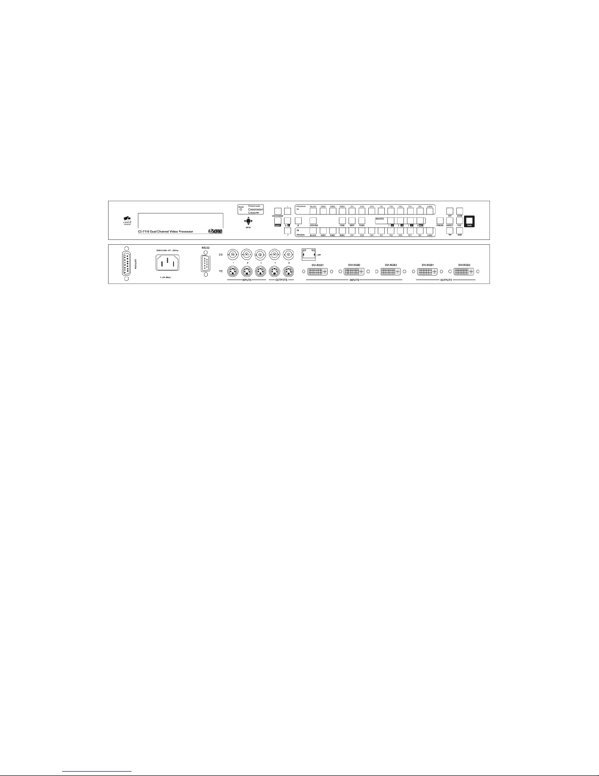
Front and rear of the C2-7110
Each C2-7000 series unit features two independent video processing and
scaling engines (CORIO®2) and two video mixers for maximum flexibility in
handling DVI, RGBHV, RGBS, RGsB, YUV, YPbPr, CV and YC (S-Video)
signals. In addition, the C2-7200 and C2-7300 range also support SDI and
HD-SDI.
The C2-7300 & C2-7310 are further extended to process high quality audio
data on 16 AES3-id inputs and outputs, as well as on the embedded data
within the SDI and HD-SDI video signals.
Throughout this manual, any feature or function relating present on all C27000 units will be referred to by ‘C2-7000 series’. Any unit-specific functions
or features will be mentioned by specific product name.
At home in both broadcast and display environments the C2-7000 series is
multiple products in one unit. The unit has three basic operating modes to
simplify control.
Switcher Mode - Equally powerful Program and Preview channels allow any
function (next Image, PIP, keying, logo, etc) to be set up and previewed,
totally independent of the Program output. Transition from Preview to
Program is by Cut, Dissolve or Special Effect when the user performs a Take.
Independent Mode - Provides all the power of two completely independent
video processors in one box, each with a full range of features including PIP,
keying, etc. Each output can deliver different formats and resolutions
simultaneously to the other. For example, a presentation being fed to a highresolution display on Output 1 via DVI can be fed to a VCR for recording on
Output 2 via Composite Video.
13

Dual PIP Mode -Any video input can be squeezed and placed into either of
two windows of any size and positioned anywhere on the screen, even
overlapping each other with user defined layer priority control. The windows
can be placed over any other video input as the background. The images in
the windows can then be seamlessly switched or zoomed. Keying can be
applied to each window independently.
General Topography - 4:4:4 RGB sampling provides full bandwidth color,
which allows precise keying, including transparent (soft) Keys. The basic
unit’s 9 video inputs accommodate multiple analog and digital video and
computer signal formats and resolutions. It handles all known HDTV formats
and any RGB resolution up to 2048x2048 - not just some predefined ones, but
virtually ANY resolution. Each of the two independent outputs delivers DVI-I,
RGBHV (or RGBS or RGsB), YUV, YPbPr, Composite and YC (S-Video).
Ultimate flexibility -The C2-7000 series’ output signal format flexibility
assures that the native resolution of virtually any digital display can be
matched. Because of the resolution calculator (included in the Windows®
Control Panel), even new resolutions can be added to the unit. Signal
parameter adjustments can be made for each video input and are stored in
individual non-volatile memories. Dedicated memory is included for multiple
integral Testcards and Logos, so the unit can easily be used as a logo
inserter. The C2-7000 series employs pixel adaptive motion compensation to
de-interlace fast moving images and its automatic 3:2 Pull-down efficiently deinterlaces video from 24 fps NTSC film.
Simple Control - The unit can be controlled from the front panel, via RS-232
or ethernet. The previously mentioned Windows Control Panel (available for
download from our Internet site) affords complete control of the unit and adds
Scripting to facilitate long, complex sequence of commands. Finally, hardware
based, switcher-like CORIO® Console allows a user to control the unit from
hardware, mimicking a classic video switcher device.
3.2 Terms of Reference
In order to operate the C2-7000 series, agreement on terminology is required.
To avoid confusion as you read through this manual, here are the terms of
reference used throughout.
Input Sources: At least nine signal inputs are available (11 on the C2-
7200/7210/7300/7310 and 17 on the C2-7260) and each of these are
buffered and made available to the unit’s video processor. The user
can modify numerous input signal parameters. In addition, the device
can determine the signal format of each input automatically so long as
the signal formats are commonly accepted worldwide standards.
Layers: Imagery is arranged in six layers and made available to the
device’s outputs. The degree of transparency can be set to make
individual layers opaque, semi-transparent or fully transparent. In
addition, with the exception of the 6thlayer (background color), the
14

layers can be positioned as desired in the ‘stack’ so that the user can
create any relationship he or she desires.
Modes: There are three modes of operation: Switcher, Independent
and Dual Picture in Picture (Dual PIP). In Switcher mode, inputs and
manipulations are shown on one output immediately and transferred to
the second output when a ‘Take’ button is pressed. In the Independent
mode, input selections and manipulations are made to appear on the
two outputs independently yielding two separate signal paths. In the
Dual PIP mode, the functionality of both processors is combined to
provide two Picture in Picture windows. The outputs are comprised of
the same signals but different key and fade values can be set for each
of the unit’s outputs.
Processor: Refers to the CORIO®2 processing engine within the unit
of which there are two. Each is able to scale, shrink, zoom and adjust
the selected input source.
Outputs: There are two output channels provided, each channel
comprising of a DVI-D, RGBHV, Composite, and YC output. The
function of each output channel depends on the mode of operation
selected. The user can select the output signal format as desired and
can set the signal resolution (except for PAL/NTSC signals).
Windows: Windows are containers for the input signals. They can be
sized and positioned as required within the output window.
3.3 Device Overview
The C2-7000 series provides a means for the user to select sources from the
inputs and present them to the two outputs in various ways. The imagery on
the outputs is comprised of the video layers of live (moving) video plus static
video sources such as internally stored logos and testcards.
The outputs are then further defined by the operational mode selected:
Switcher, Independent and Dual PIP (Picture in Picture).
15

3.4 Models available
There are different models in the C2-7000 series – either incorporating a
number of SDI inputs / output or not, or using a 10-way programmable button
panel or 48-key non-programmable front panel.
The following pictures detail the differences between the units:
C2-7100 & C2-7110 front and rear panels:
C2-7200 & C2-7210 front and rear panels:
C2-7260 front and rear panels:
C2-7300 & C2-7310 front and rear panels:
16

In summary, the following table details the main differences:
Model Inputs Outputs Keys
C2-7100 3xDVI-I 3xCV 3xYC 2xDVI-I 2xCV 2xYC 10
C2-7110 3xDVI-I 3xCV 3xYC 2xDVI-I 2xCV 2xYC 48
C2-7200 3xDVI-I 3xCV 3xYC 2xSDI 2xDVI-I 2xCV 2xYC 2xSDI 10
C2-7210 3xDVI-I 3xCV 3xYC 2xSDI 2xDVI-I 2xCV 2xYC 2xSDI 48
C2-7260 3xDVI-I 3xCV 3xYC 8xSDI 2xDVI-I 2xCV 2xYC 2xSDI 48
C2-7300 3xDVI-I 3xCV 3xYC 2xSDI
+ 16xAES3-id
C2-7310 3xDVI-I 3xCV 3xYC 2xSDI
+ 16xAES3-id
2xDVI-I 2xCV 2xYC 2xSDI
+ 16xAES3-id
2xDVI-I 2xCV 2xYC 2xSDI
+ 16xAES3-id
10
48
10-key panels are programmable; 48-key panels are not.
3.5 Input Sources
The C2-7000 series accepts a very wide range of input types. Adaptors are
provided to allow configuration of the device to accept and process virtually
any image source. The device will automatically identify the signal type or
image resolution for virtually any input and manual intervention is possible for
many non-standard inputs.
Valid processor inputs also include sources not associated with the input
connectors. Firstly there are multiple test cards which are stored within the
device’s non-volatile memory for later recall. Secondly it is even possible to
internally cascade one output using it as the Input Source for the second
processor.
3.6 Outputs
Two Outputs are provided on the C2-7000 series. The user can select the
type of output signal desired for each Output and each Output can be
adjusted independently of the other. The exact function of the Output depends
on the mode as explained previously.
3.7 Windows
Windows can be thought of as containers for imagery. Input selections from
the various connectors as well as integration of internal sources such as
Logos are all part of the Windowing capabilities of the C2-7000 series.
There are two scalable windows available for use, ‘A’ and ‘B’––one for each
processor in the C2-7000 series–– and each is part of the layering hierarchy
used in the C2-7000 series. Images can be zoomed, shrunk, keyed,
positioned and scaled within the Window or as a part of the Window. There is
also a Lock Source Window ‘Z’, plus Logo ‘a’ and Logo ‘b’ none of which are
re-sizeable.
The Window itself can be thought of as a hole cut into the overall output
image. The edges of the cut out can be hard or soft and the nature of the
17
Window itself can be opaque, semi-transparent or invisible depending on how
the various Layers, Fade levels and Keyers are set up.
Within the nomenclature that follows, the Windows will be associated with one
or both of the two Outputs as explained in the section detailing Modes of
Operation.
Windows are an integral part of the C2-7000 series and play a central part in
understanding how to operate the device.
3.8 Layers
There are six image layers comprising of two static logo sources (stored
internally in the device), two scalable windows that contain video, a lock
source and, finally, a color background which is always the 6thlayer.
The image layers are given designators for the purposes of identification
when operating the C2-7000 series. The designators are case sensitive. The
letters and their meanings are as follows:
Window Description
a Logo “a” (Static - not scaled)
b Logo “b” (Static – not scaled)
A Window “A” (Live – scalable)
B Window “B” (Live – scalable)
Z Window Z Lock Source (Live – not scaled)
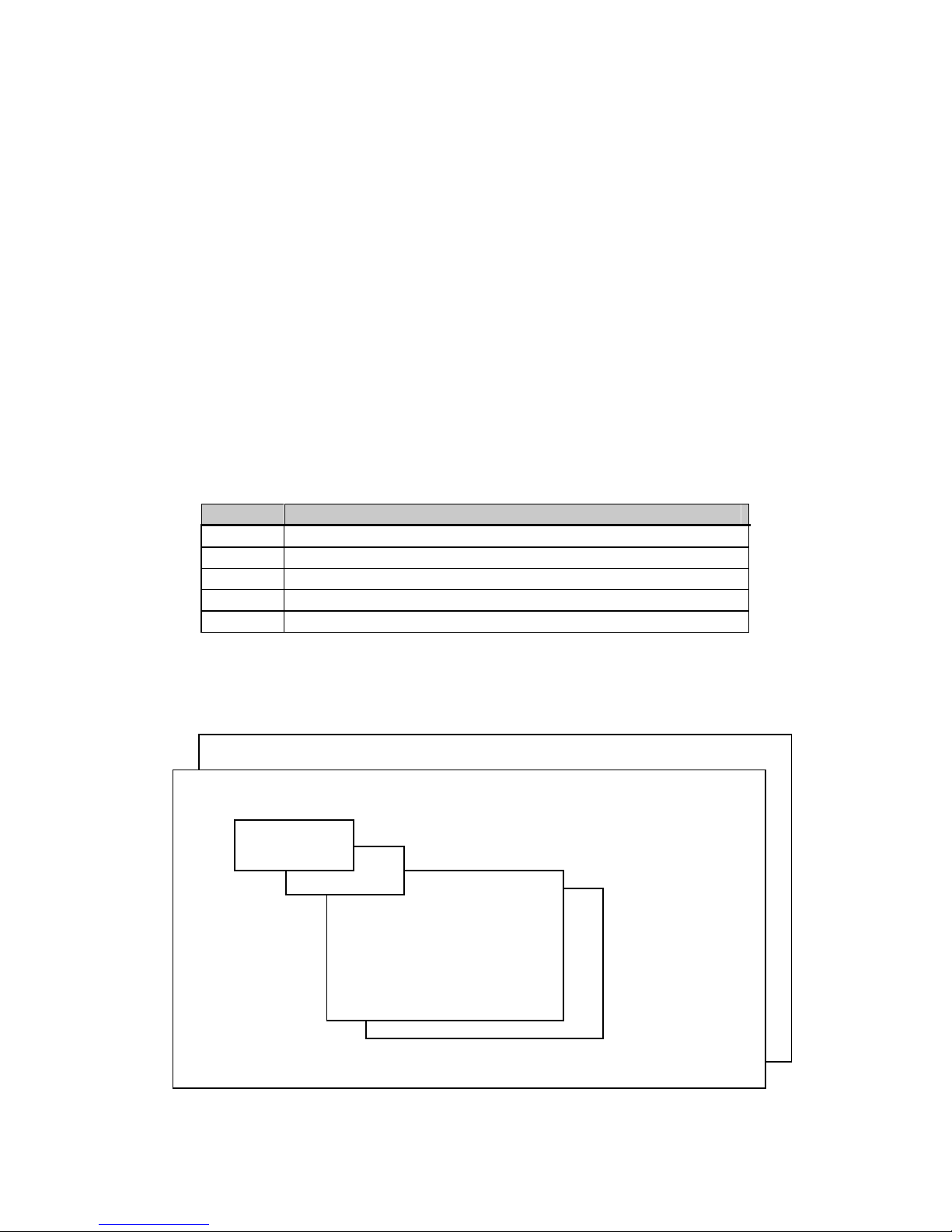
Since the color background layer is always layer number six, it can’t be
moved and is given no designator. In the factory default condition, the layers
are arrayed as shown:
Color Background
Z (Lock Source)
a
b
A
B
18
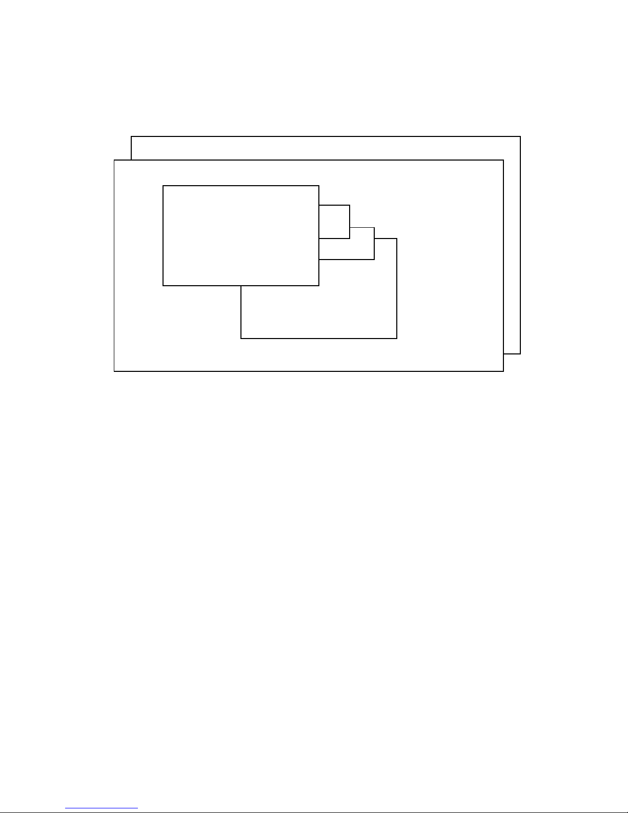
With the exception of the color background layer, the layers can be re-ordered
so that different orientations are displayed. For example, the combination
shown below could be created which would mean that the Window “A” layer
would have primacy over all the others:
Color Background
Z (Lock Source)
A
a
b
B
The degree of transparency of any of the layers can be changed so that the
layer(s) beneath are visible, semi-visible or invisible. As an example, if layer
“A” above were expanded to cover all of the available image area and made
fully opaque, none of the layers beneath it would be visible. By the same
token, if Layer “A” were made semi-transparent, the layers beneath would be
dimly visible. Should layer “A” be made fully transparent, then it would seem
to disappear completely.
The powerful Keyer function of the C2-7000 series takes advantage of this
feature to superimpose portions of one window over another. Portions of a
layer are made semi-transparent or invisible. Certain colors are made invisible
the result is one image appears to float above another on the layer stack.
3.9 Modes
The three modes available in the C2-7000 series are Switcher Mode,
Independent Mode and Dual Picture in Picture (Dual PIP) mode.
3.9.1 Switcher Mode
The switcher mode configures the two outputs to function in a familiar preview
and program arrangement. The output in this mode is actually a display of a
single Window (A), optional Lock Source (Z) and optional Logo (a). The
Window (B) and Logo (b) are used internally for program / preview processing
and as such are unavailable to the user.
19

When an input selection is made, it instantly appears on Output 2––a Preview
Output––but no action is taken on Output 1. The “Program” Output (Output 1)
retains the last image selected when in the Switcher mode until the user
presses button number 2 on the front panel. Button number 2 is the ‘Take”
button when in the Switcher mode and pressing it causes the image present
on Output 2 to also appear on Output 1. Special control logic within the C27000 series allows the movement of the image from Output 2 to Output 1 to
be either instantaneous or the new Output 1 image can gradually replace the
previous image on Output 1 via a cross fade or a wipe. The time available for
the cross-fade or wipe can be up to 5 seconds, controlled in .1-second
increments.
3.9.2 Independent Mode
In the Independent mode, the dual processor circuitry is divided into two
separate but equal signal processors. Window “A” and Logo “a” is dedicated
to Output 1 and Window “B” and Logo “b” is dedicated to Output 2. Each of
the Outputs can have a separate Lock Source (Layer Component Z), separate
Color Background and separate Input Sources.
Graphically, the two Outputs layers will appear as shown:
Color Background – Output 1
1Z Lock Source
Window “1A”
Logo “1a”
Color Background – Output 2
2Z Lock Source
Logo “2b”
Window “2B”
From the drawings above, it can be seen that a limited layering scheme is in
place while in the independent mode. You can utilize the transparency feature
and the Keyer capability on each Output to make any portion of the window
visible.
You can use the input buttons to select the images held within the windows
and the selection process would be for only one output without having an
effect on the other.
Similarly, you can make the Color Background layer different colors or cover it
with a Lock Source or Window.
Finally, the logo generator can be employed to superimpose a logo over each
Output independently.
20

3.9.3 Dual PIP Mode
In the dual Picture In Picture mode, the same Lock Source (Layer Component
Z) is applied to both Outputs 1 and 2. The Imagery present on those Outputs
therefore will be locked to the single Lock Source even though there are two
Outputs available.
From a practical standpoint, this means that there is only one lock source
available and both outputs will contain the same lock source imagery.
The Keyers can adjust the components of each Window independently so as
to make a portion of the underlying Window pierce the overlaying Window and
the logos can be used as desired in the Output imagery.
Two Windows are available, “A” and “B”, on each of the two Outputs. Each
Output displays the Windows at the same position and sizing. By changing
the order of the layers either PIP can be placed in front of the other and the
balance of the layers can be utilized as well.
Color Background – Output 1
1Z Lock Source
Logo “1a”
Window “1A”
Window “1B”
Logo “1b”
Color Background – Output 2
2Z Lock Source
Logo “2a”
Window “2A”
Window “2B”
Logo “2b”
Inputs switched into Windows “A”, “B” and “Z” appear on both outputs (in
other words, the imagery present in Window 1A is the same as 2A and the
imagery present in Window 1B is the same as that present in Window 2B).
Positions and sizing is also the same for both Outputs however you can utilize
independent Keying, fading and layering on each output.
21

4.0 UNPACKING AND INSTALLATION
4.1 Shipping Carton
The C2-7000 series arrives double boxed for maximum protection during
shipping. You are encouraged to retain both boxes and all packing material so
the unit can be returned in the unlikely event that repairs should ever become
necessary.
4.2 Furnished Accessories
Carefully unpack the carton and perform an inventory of the contents. In
addition to the C2-7000 series Dual Channel Video Processor, the standard
accessories include:
2 RGBHV I/O Adaptors, DVI-A to HD15
1 AC Power Cable
1 Operations Manual
1 Rack-mount Kit, 2 Ears and 8 Screws
If any items are missing or defective, contact your supplier. If you are unable
to resolve the problem with your supplier, contact TV One via the web at
http://www.tvone.com/support for prompt replacement.
22
5.0 FUNCTIONAL CHECK
5.1 Important Safety Instructions
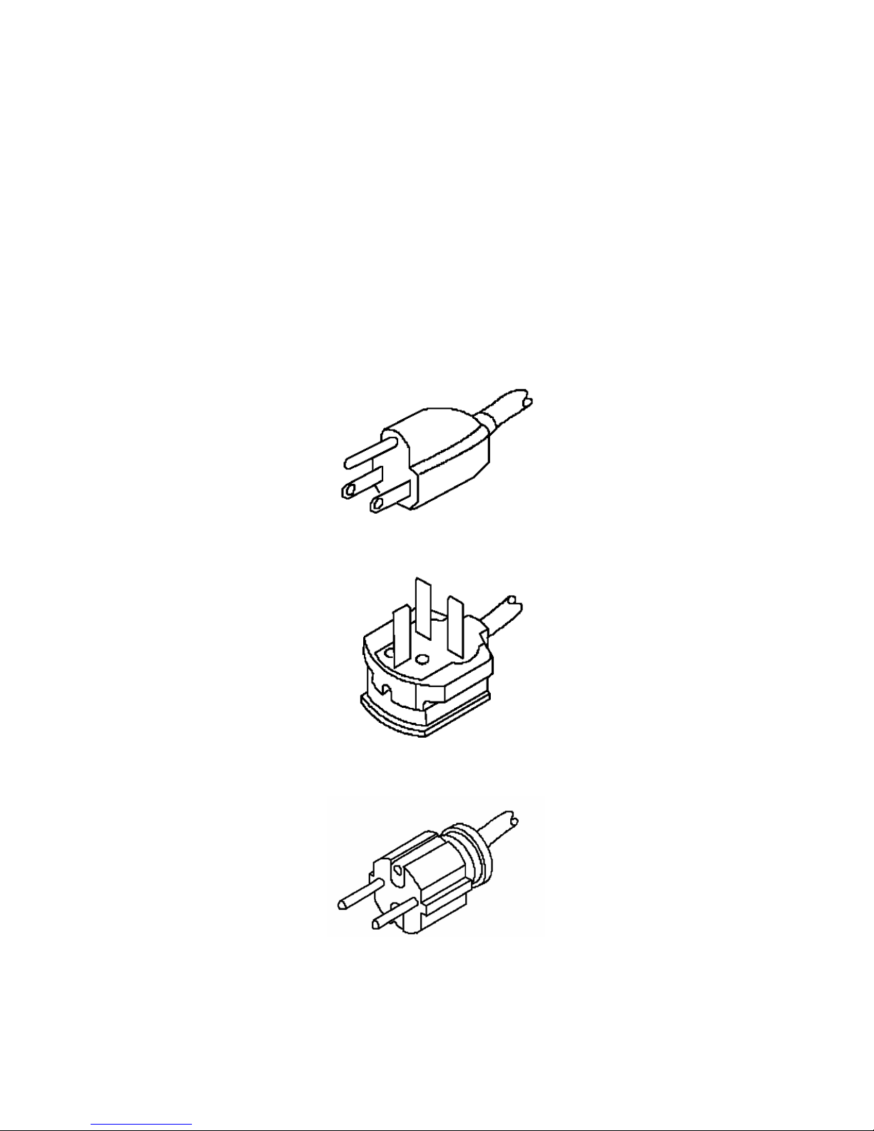
The AC power cable (Mains Lead) furnished with the unit will conform to the
type in use at your geographic locale. Please compare the plug on your cable
with the three types of power cable plugs currently being shipped to make
certain you have received the correct power cable.
If you did not receive the correct cable, DO NOT attempt to modify the
incorrect cable. Instead, immediately contact your dealer or contact TV One at
the sales office nearest to your geographic location and request the proper
cable.
US AC Cable Plug Example:
UK AC Mains Lead Plug Example:
EU AC Mains Lead Plug Example:
AGAIN, DO NOT ATTEMPT TO MODIFY AN INCORRECT AC CABLE
(MAINS LEAD). REPLACE IT WITH A CORRECT PART PRIOR TO USING
THE C2-7000 series.
23
 Loading...