

Page 1
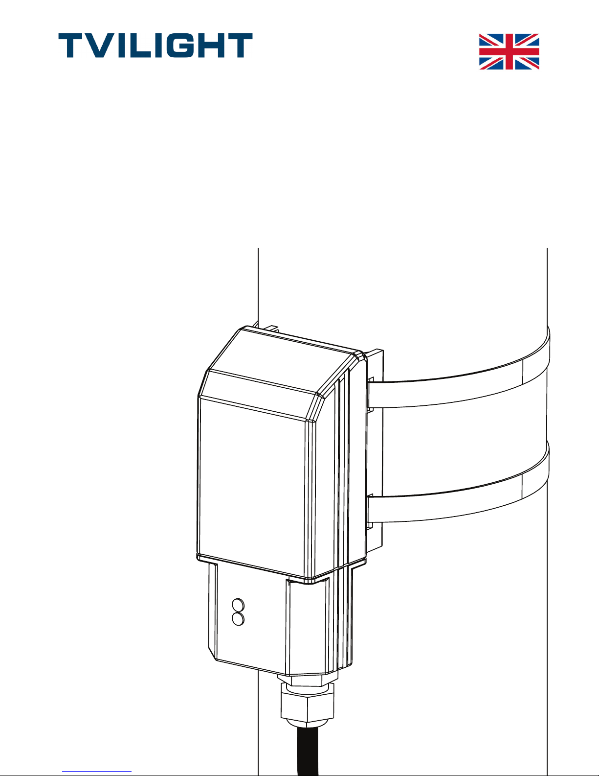
SkyLite V3.1External
Installation Manual
English
PR161926 | Rev. D | 08/06/2018
Page 2
PR161926 | Rev. D | Page 2 of 10
Version Author Date Changes Approved by
v1 Kepa Noguera
Idiondo
25/10/2017 First version
v2 Kepa Noguera
Idiondo
07/11/2017 UV sleeve Henri Eskonen
v3 Henri Eskonen 31/01/2018 Combined
Grommet and Cable
Gland Manuals;
formatting; address
Rev. D Henri Eskonen 08/06/2018 Corrected footer;
removed UV
sleeve steps;
changed warning
on page 10; minor
formatting; change
version from #s to
letters
AvB, RB
Page 3

PR161926 | Rev. D | Page 3 of 10
In order to function properly, SkyLite v3.1 must be
connected to a dimmable driver/ballast.
NOTE: Some dimmable drivers/ballasts must be
programmed/set to dimmable mode. If this has not been
done, SkyLite v3.1 will not be able to dim the connected
luminaire.
ATTENTION:
TVILIGHT BV / Rozenburglaan 3, 9727 DL, Groningen, the Netherlands
NL+31 (0)50 800 3240 / [email protected] / www.tvilight.com
Page 4
PR161926 | Rev. D | Page 4 of 10
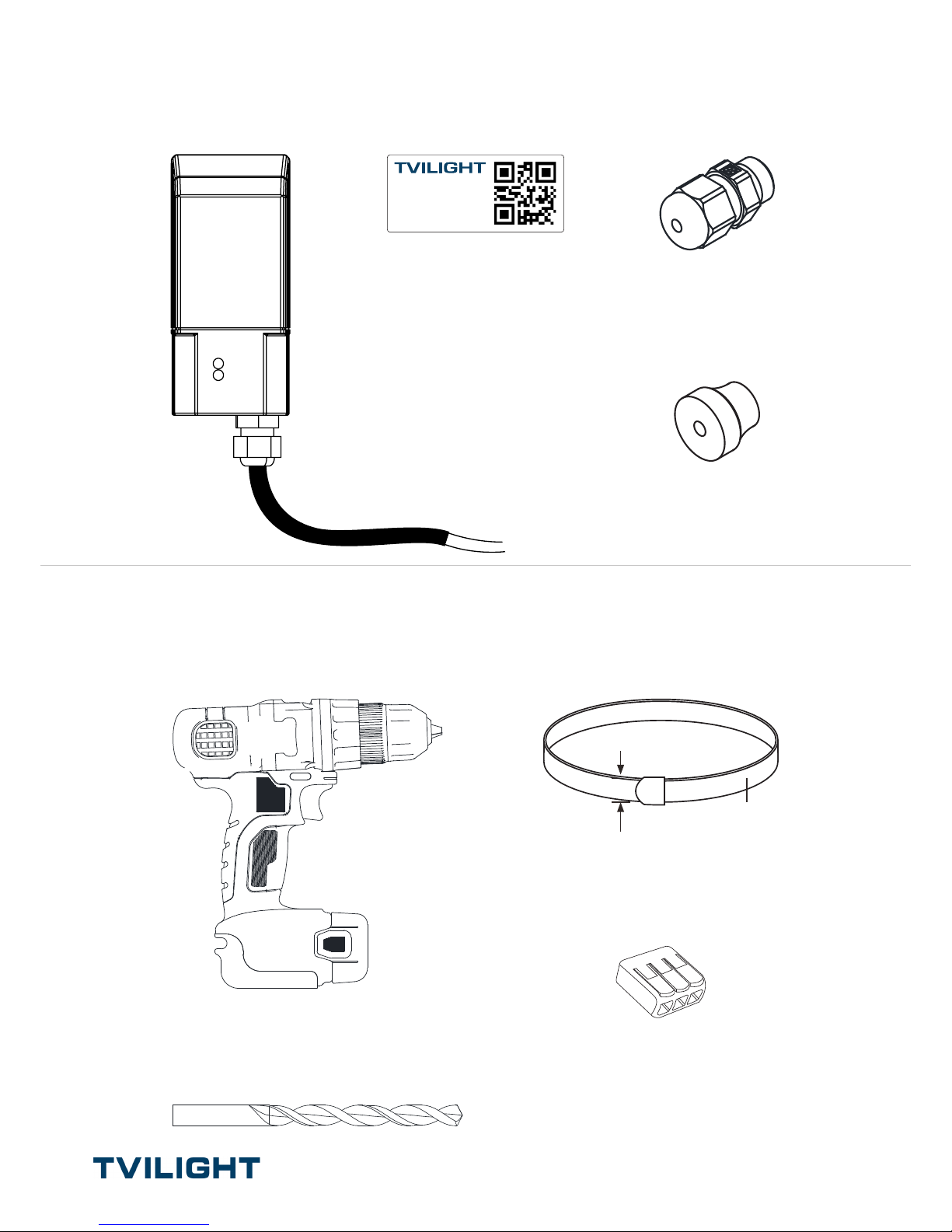
In box:
You’ll need:
Pole ID Label
www.tvilight.com
TVI-SKLEXT1-01-0014
5.5m Cable
SkyLite V3.1
Generic Strap x 2
Max = 11mm
Min = 8mm
Wago x 4
OR
16 mm Grommet
M16 Cable Gland
Drill
M16 Threaded
OR
16 mm
Page 5
PR161926 | Rev. D | Page 5 of 10
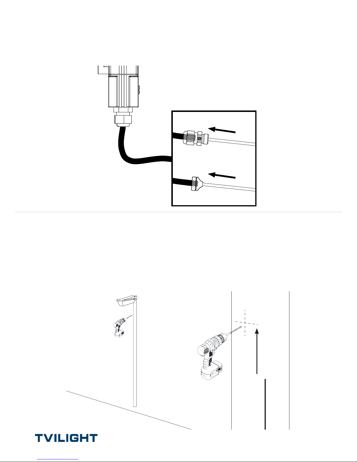
2. Drill hole into the pole:
- M16 threaded (Cable Gland) OR
- 16 mm (Grommet)
5m
Note: For added protection against rust, the use of an anti-corrosion spray such as
WD40 Corrosion inhibitor or equal is recommended.
1. Push Cable Gland/Grommet over the cable
and UV Protective Sleeve
Note: Leave some UV Sleeve in the Cable Gland/Grommet.
OR
Page 6
PR161926 | Rev. D | Page 6 of 10
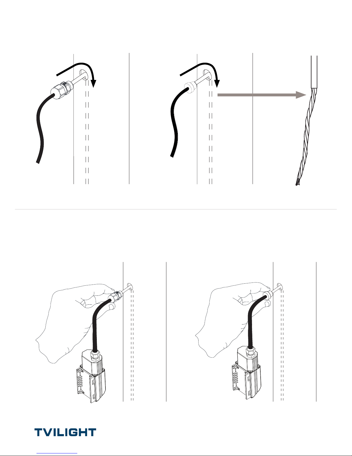
3. Run wire into hole in the pole
4. Insert Cable Gland/Grommet into hole in
the pole
Twist the end
leads of the wires
OR
OR
Page 7
PR161926 | Rev. D | Page 7 of 10
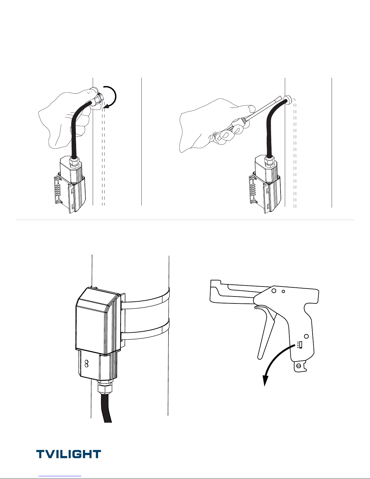
6. Strap product to the pole
5. Screw Cable Gland OR press Grommet into
the pole
* Ensure Tensioning Tool is set
to maximum tension (#4)
Tensioning Tool
NOTE: Make sure the UV Protective Sleeve is inside the Cable Gland/Grommet when
tightening.
OR
Page 8
PR161926 | Rev. D | Page 8 of 10
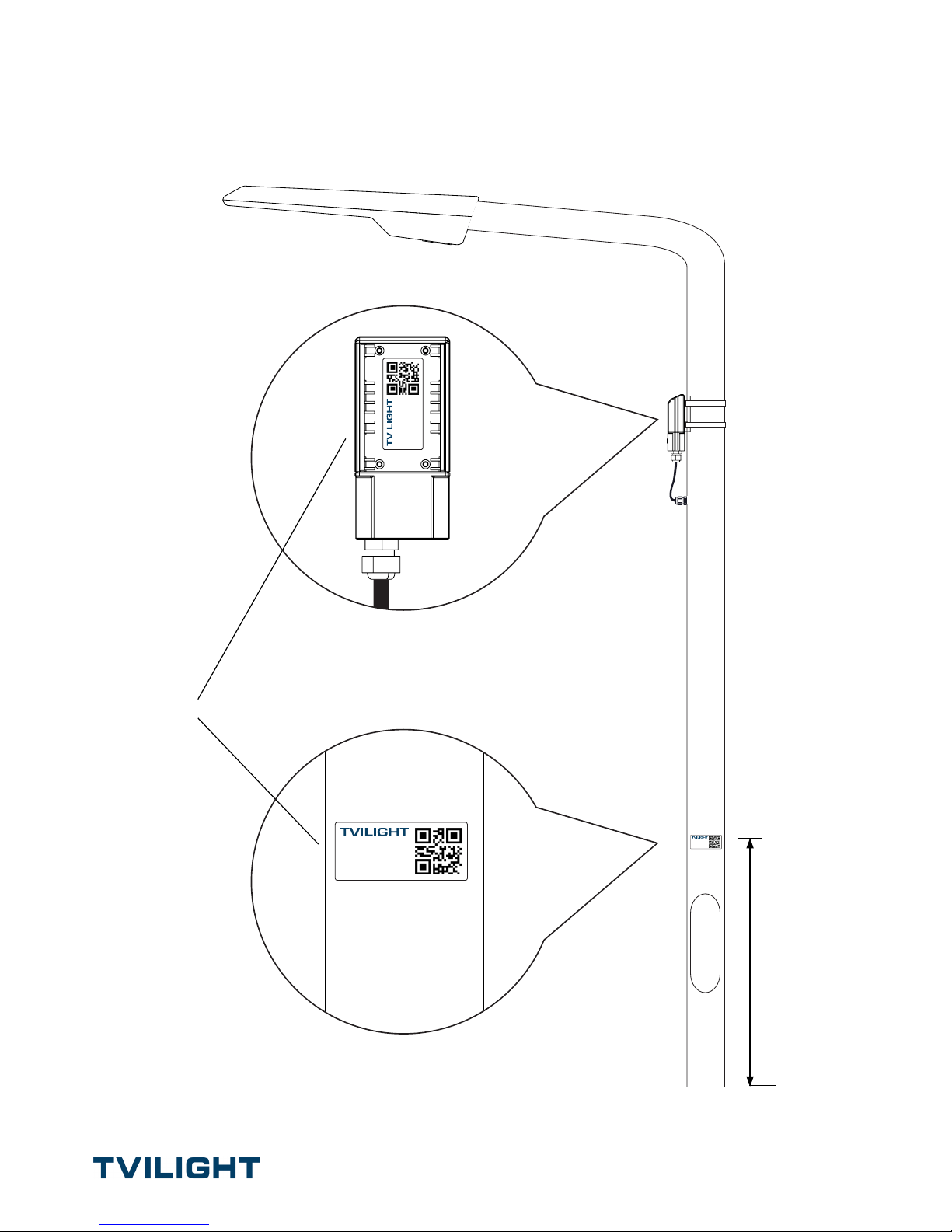
7. Apply Pole ID Label to the pole
1 m
SAME
www.tvilight.com
TVI-SKLEXT1-01-0014
www.tvilight.com
TVI-SKLEXT1-01-0014
www.tvilight.com
TVI-SKLEXT1-01-0014
Ensure that the Product and Pole ID Labels match.
Page 9
PR161926 | Rev. D | Page 9 of 10
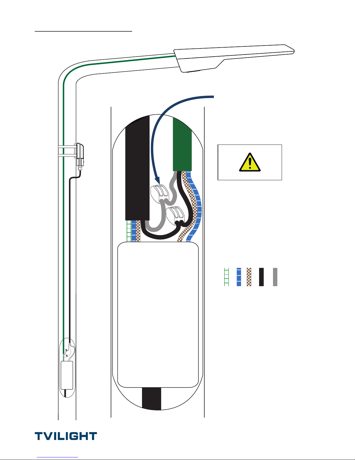
Wiring Diagram
GND N L DC+ DC-
Connector
(e.g. Wago)
N
L
DC-
DC +
Junction Box
GND
L
N
WARNING:
If not correctly connected product might not
function or it might be permanently damaged.
Page 10
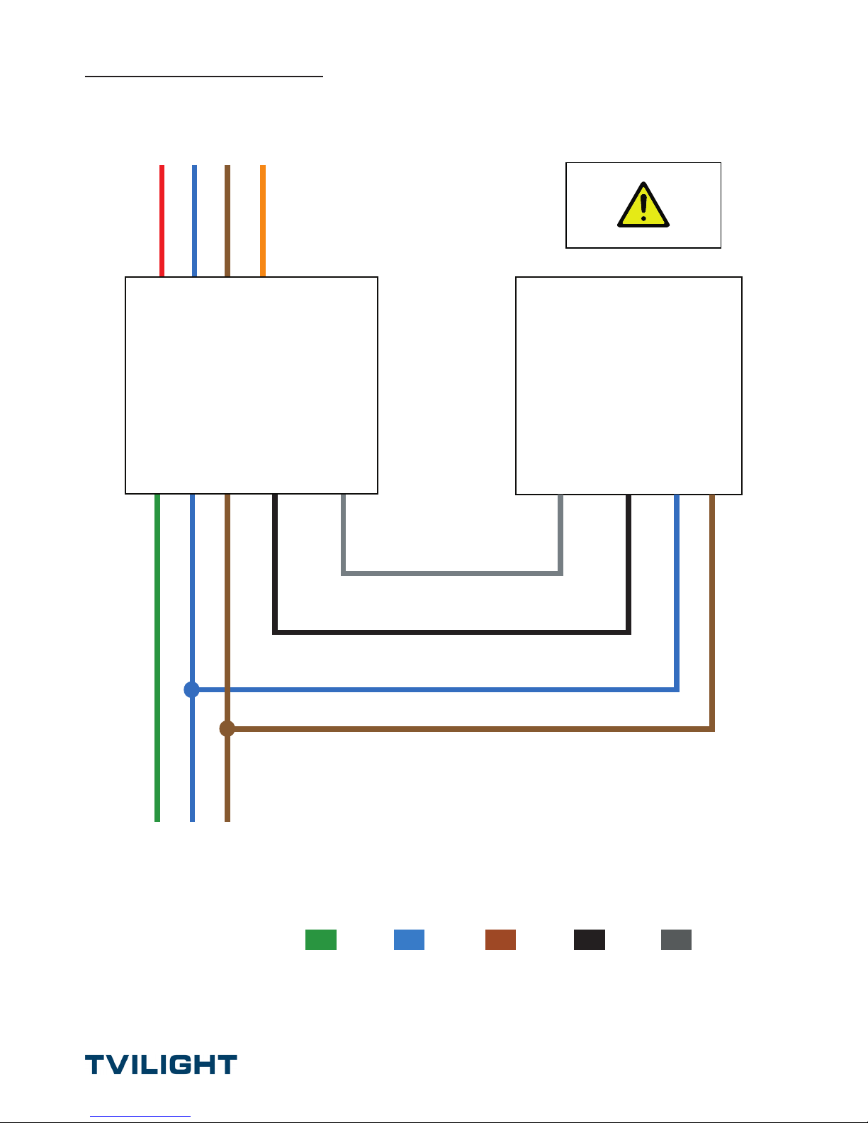
PR161926 | Rev. D | Page 10 of 10
GREY
1-10V-
or
DALI-
BLUE
N
BROWN
L
GREEN
GND
BLACK
1-10V+
or
DALI+
To Armature
To Mains
TVILIGHT
SKYLITE V3.1
GND N L
Driver
GND N L
1-10V-
or
DALI-
1-10V+
or
DALI+
1-10V-
or
DALI-
1-10V+
or
DALI+
N L
Wiring Diagram
WARNING:
If not correctly connected product might not
function or it might be permanently damaged.
Note: Observe all laws, guides and recommendations with regards to
electrical installation and safety.
 Loading...