

TVH EL510-35PLUS Operation Instructions Manual
PROGRAMMABLE CODE SWITCH
OPERATION INSTRUCTIONS
Read and Save
16355 SOUTH LONE ELM ROAD
OLATHE, KANSAS 66062 • USA
PHONE: 913-829-1000 • TOLL FREE: 800-255-4109 • FAX: 913-829-9208
www.smhco.com
16355 SOUTH LONE ELM ROAD
OLATHE, KANSAS 66062 • USA
PHONE: 913-829-1000 • TOLL FREE: 800-255-4109 • FAX: 913-829-9208
www.smhco.com
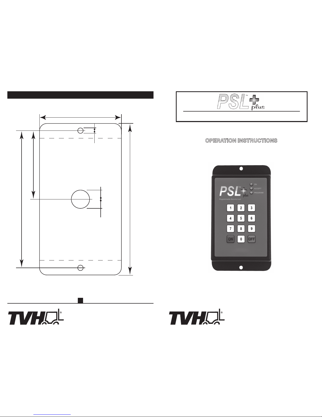
MOUNTINg TEMPlATE
4 ¹¹⁄
₁₆
"
/ 119.1mm
2 ¹¹⁄
₃₂
"
/ 59.5mm
2 ¹³⁄
₁₆
"
/ 71.4mm
5 ³⁄
₁₆
"
/ 131.8mm
³⁄
₁₆
"
/ 4.8mm
⁵
⁄
₈
"
/ 4.8mm
EL510-35PLUS
SSI0312 Printed in USA
15
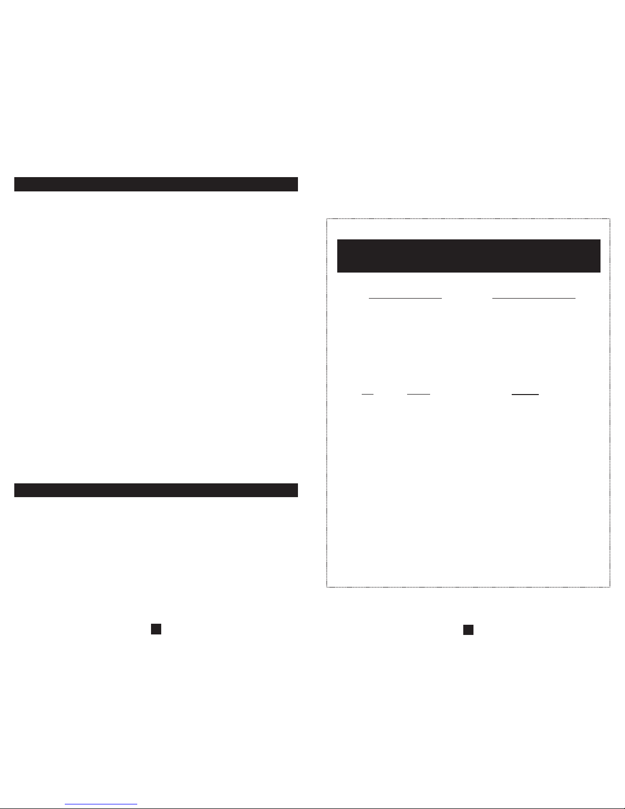
PSL+™
Reset Code and Quick Reference Instruction Insert
Serial # Reset Code
User Access: Enter User # + User Code + “on”
Supervisor Access: Enter “00” + Supervisor Code
Reset Procedure: Enter “00” + “0000” + Reset Code
SUPERVISOR MENU
Key
1
2
3
4
5
6
7
8
9
ON
0
OFF
Display
Flashing Red
(none)
1 amber + 3
1 amber + 4
1 amber + 5
1 amber + 6
1 amber + 7
1 amber + 8
1 amber + 9
(none)
(none)
(none)
Function
Program User Numbers
Last User Function
Enable/Disable ASO function
Set ASO Delay Time:
Enable/Disable MC function
MC Control Internal/External:
Set Maintenance Cycle Length
Set time between MC alerts
Check various times
Turn on Output (and exit menu)
Reset Maintenance Cycle
Exit Supervisor Menu
Instruction Booklet
with Reset Code and Quick Reference
14
FEATURES:
The PSL+ ™ Programmable Security Lock is an enhanced version of the PSL ™ product with
several additional features. Like the original, this version is primarily designed for use with both
battery and I.C. engine powered vehicles to prevent unauthorized operation of the vehicle.
Expanded Voltage Range
- The PSL+ is rated for nominal input voltages from 12 to 90VDC.
Expanded User Capability
The PSL+ can be programmed for up to 99 unique users. Once installed, the PSL+ requires entry of a twodigit user number and valid four-digit access code before the vehicle or equipment can be operated. All user
codes can be reprogrammed and unused user numbers can be temporarily disabled for additional security.
Last User Identification
The PSL+ can identify to the supervisor the user number of the last user of a vehicle.
Automatic Shut-Off
The PSL+ incorporates a feature that detects vehicle activity. If the vehicle has been inactive
beyond a specified period of time, the PSL+ will deactivate securing the vehicle. This feature is
optional and can be activated or deactivated as desired.
Maintenance Alert
The PSL+ can accumulate vehicle usage time and provide audible and visible signals indicating when
vehicle maintenance is due. After maintenance is performed, the cycle can be reset as desired. This
feature is optional and can be activated or deactivated by supervisor.
Accumulated Time
The PSL+ accumulates total vehicle usage time. This accumulated time can be accessed through
the Supervisor Code.
Even the supervisor’s access code can be changed using the factory programmed reset code.
Installation of the PSL+ remains simple with just 4-5 wires to connect. Diagrams showing typical
wiring schemes are included in this manual.
Case: ABS plastic
5
3
/16”h x 2 13/16”w x 1.0”d
Two (2) 3/16” mounting holes, 4 11/16” center to center
Keypad: Contacts internally sealed, moisture resistant
Voltage: Input range 12-90VDC
Current: Less than 30 mA with unit inactive; less than 90 mA with unit active.
Output: Contact rating up to 10A maximum through 48V
Maximum 1A contact rating above 48V
For loads greater than 10A use external relay
SPECIFICATIONS:
1
WARRANTy NOTE
The PSL+ is a sealed unit. There are no user serviceable parts inside. Removing or tampering with
the epoxy encapsulant will void the warranty.
Upon installation of the PSL+, the unit must first be programmed with a supervisor code. When the
unit is first powered up, or powered up for the first time after executing a reset procedure, it will
automatically go into supervisor code programming mode. This mode is indicated by alternately
displaying 3 amber flashes and 3 red flashes. When in this mode, simply enter the four digits you
would like to use as the supervisor access code. You must use all numerical digits; the “on” and
“off” keys may not be incorporated into the supervisor code. All combinations of numerical digits
are acceptable except 0000. For best security, we recommend avoiding repetitive digits like 4444
and sequential digits like 1234. You will hear a short beep to acknowledge each key entry. If an
illegal character is selected, an error beep consisting of a short beep followed by a long one will be
sounded. If this occurs, you must continue from the point prior to the illegal character being pressed
or remove power and start the code entry process over. When an acceptable 4-digit supervisor code
has been entered, the amber “accept” LED will be illuminated and the unit will stop responding. At
this point the new supervisor code has been programmed and the unit must be powered down to
allow for normal start up before proceeding. It may be a good idea to write down the supervisor
code and keep it in a safe place so you don’t forget it, but if you do the supervisor code can be reset
and reprogrammed (See page 10). Note: If an undesired key is entered during supervisor code
entry, the procedure can be aborted by removing power from the unit.
Quick Steps – Supervisor Programming
1. Enter desired 4-digit supervisor code. Unit will beep with each key depression.
2. Power down unit to save code.
Entering Supervisor Mode is necessary for configuration of programmable settings and retrieval
of data stored in the PSL+. The procedure for entering supervisor mode is a simple two step
process. Each key entry is acknowledged with a short beep and errors are indicated with the short
+ long beep pattern. Keystrokes are timed with a limit of 15 minutes between keystrokes or the
process will be aborted. The process may also be aborted manually by pressing “off”. The output
must be off before beginning this procedure:
1. Enter “00”. This identifies you as the supervisor.
2. Enter the four-digit supervisor code. Upon completion the entry is checked. If the entry is
correct, the amber “accept” LED will acknowledge the entry and then the red and amber LEDs
will begin to flash alternately to indicated the unit has entered supervisor mode. If incorrect,
the error beep is sounded and the process aborted.
Quick Steps – Entering Supervisor Mode
1. Enter “00”.
2. Enter four-digit supervisor code. The “accept” LED will acknowledge the entry and then the red
and amber LEDs will begin to flash alternately to indicate the unit has entered supervisor mode.
II. ENTERINg SUPERvISOR MOdE:
2
I. gETTINg STARTEd / PROgRAMMINg ThE SUPERvISOR COdE:
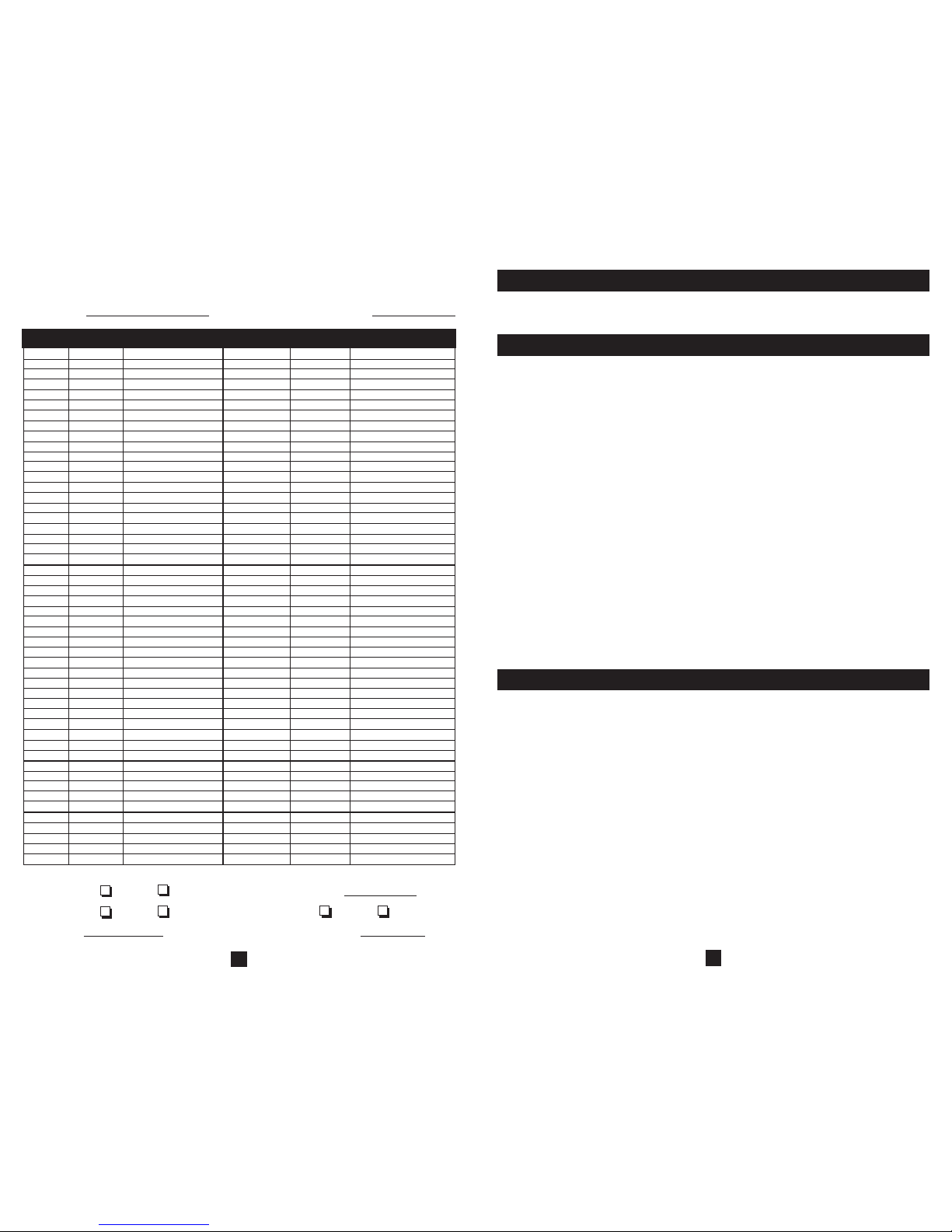
User # Code Name/Group
User # Code Name/Group
01
02
03
04
05
06
07
08
09
10
11
12
13
14
15
16
17
18
19
20
21
22
23
24
25
26
27
28
29
30
31
32
33
34
35
36
37
38
39
40
41
42
43
44
45
46
47
48
49
50
51
52
53
54
55
56
57
58
59
60
61
62
63
64
65
66
67
68
69
70
71
72
73
74
75
76
77
78
79
80
81
82
83
84
85
86
87
88
89
90
91
92
93
94
95
96
97
98
99
Automatic Shut Off: Enabled Disabled Delay Time minutes
Maintenance Cycle: Enabled Disabled Internal External
Cycle Time hours Alert Intervals minutes
Supervisor Code: Reset Code:
Optional Unit Worksheet
13
 Loading...