

Page 1

Pipe Inspection Camera System
Operation Manual
Model No.: 3199F
Read this Operation Manual carefully before using this tool
Page 2

[ INTRODUCTION]
The pipe inspection syst em is a po wer ful set o f tools that helps you locat e and diagnose problems in a pipeline
system.
The s ystem is widely us ed in inspections o f Sew er, central air condit ioning, chimney, plumbing, building, c able pipe
and pipes ventilation syst ems and other places.
[GENERAL SAFETY RULES]
Precautions
Read all safety w arnings and instructions. Failure t o follow warnings and instructions may result in elec tric
shock, re and/or serious injury.
1. Save this operation manual for future re ferenc e.
2. Do not operate this device in explosive atmospheres, such as in the presence of ammable liquids, gases, hazardous
chemicals, superheated liquid or heavy dust. It may create spark s which may ignite the dust or fumes.
3. The camer a head and the push c able are water proof, how ever, the battery pack, DVR and c onnecter cable ar e not. Do
not expose them t o water or r ain. This incr eases the risk of electric al shock.
4. Avoid using the device in environments of extr eme cold, heat or humidity as it ma y damage the device.
5. Do not dr op or pr ess hard on the device.
6. Always backup y our data bef ore c onnecting your SD memor y card to this system. The manufactur er is not r esponsible for
any data o f damage on your SD memory c ard f or any reason.
7. Do not disconnect the unit while rec ording or playing back. It may damage the unit and/or the SD memory car d.
8. Only qualied person are allow ed to repair this device. Service or maintenanc e performed by unqualied person could
result in in jury.
9. Do not use this device in places where there is high voltage equipment. The device doesn’t contain high voltage protection
and isolation.
10. Check or maintain this device regularly, repair it or replace new par ts if there is any damage.
[APPLICATION AND KNOW YOUR TOOL]
Application
Suitable for pipes at diameter of 25mm-200mm. Ability to go through 90° bend places with diameter at 50mm.
Know Your Tool
The pipe inspec tion system includes the f ollowing f our main parts: Camera head, c able r eel, battery pack and
DVR.
The c amera head includes 12 high-light white LEDs and a highly scratch-resistant sapphire lens cover; this
coupled with stainless steel housing allow the camera to withstand repeated hits in various pipes.
Flexible stainless steel spring and associat ed c omponents make the camera head possible to go through bend
pipes. Also the cable reel is mounted and r otatable in the case theref ore the berglass rod cable can be pushed
in and out without the need to hold the r eel. Further, the bat ter y pack pr ovides power supply f or the syst em
and the DVR monitor c an recor d video and take photos.
1
Page 3
4
2
5
7
8
9
10
13
11
12
3
1
6
3
2
1
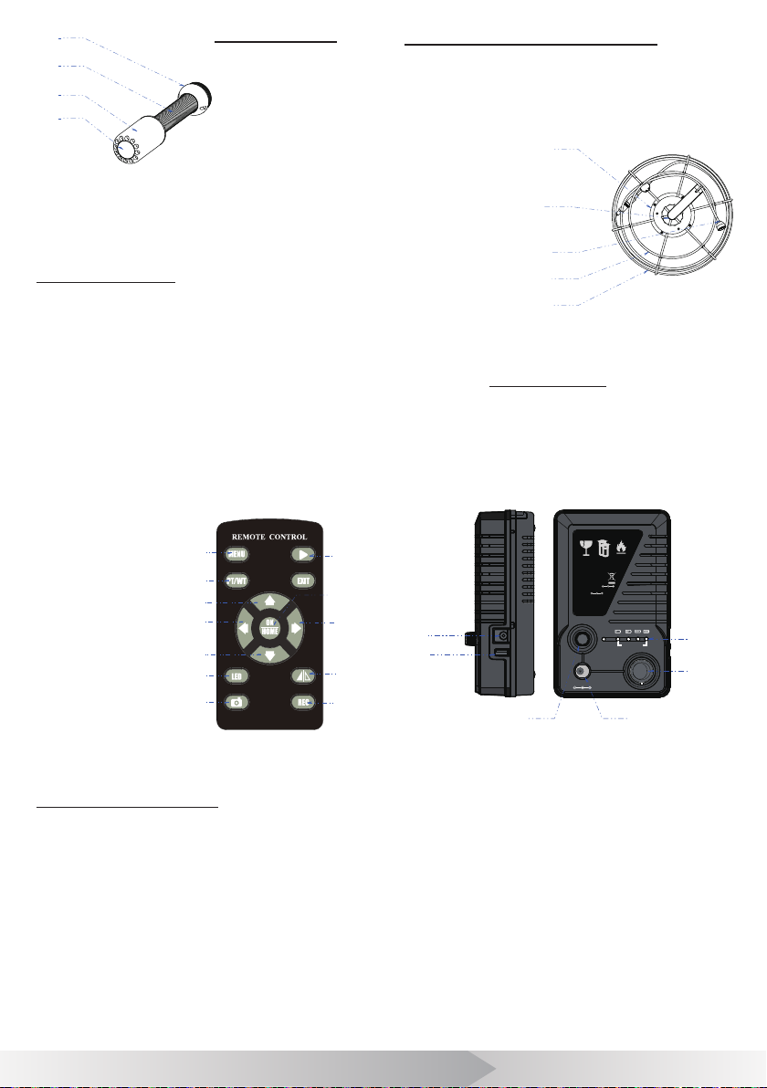
Figur e 1. Camera Head
Camera Head
1.. Sapphire Lens
2. 304#Stainless Steel
Shell
3. Stainless Steel Spring
4. Gold Connecter
Remote control
1. Menu: S elect Menu
2. Playback: Playback Mode
3. Pt/Wt: Reserve Function
4. Exit: Exit Menu
5. Up: Select Up /Prev ious It em
6. OK & Home: Conrm /S elect Menu
7. Left: Select Left Item
8. Right: Selec t Right Item
9. Down: Select Down/Next Item
10. Mirror: Mirr or A nd Flip Ima ge
11. LED: A djust The Led Brightness
12. REC: St ar t /Stop R ec or ding
13. Photo: Take Phone
Cable wheel and push cable
1. Rotation Mechanism
2. Handle
3. Cable Connect or (To Camera)
4. Cable Wheel
5. Push Cable
1
2
3
4
5
Figure 3. Cable wheel and push cable
Battery Pack
1. LED (bat ter y lev el indicator )
2. Pow er Switch
3. D C 12V R e c har gin g
4. Fuse
5. USB Output (DC 5V)
6. DC 7.4V Out put
IF DAMAGED
Lithium Ion Battery
DO NOT LOAD OR TRANSPORT
CAUTION!
PACKAGE IF DAMAGED
CAUTION!
6
5
Lithium Ion Battery
DO NOT LOAD OR TRANSPORT
PACKAGE IF DAMAGED
Do not short circuit.
Do not incinerate.
Do not disassemble.
Input
Output
Green LED
RED LED
Warning :
Read instructions
before use.
DC 12V Recharge Only
: DC 12V
:
7.4V DC Max.48.8Wh
: Fully charged
: Charging
IF DAMAGED
Battery Level
USB 5V OUT
DC 6-12V OUT
1
2
Figure 2. Remote control
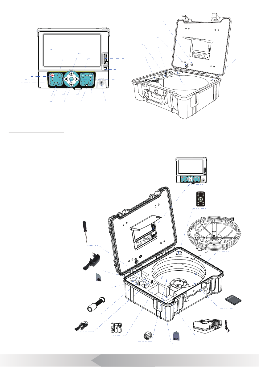
DVR AND TOOL BOX
1. Playback: Playback Mode
2. Left: Select Left Item
3. Menu: Sele ct Menu
4. Power Indicator LED
5. Exit: Exit Menu
6. OK & Home: Conrm/Select Menu
7. Down: Select Down/Next Item
8. LED: Change The Led Brightness
9. IR For Remote Control
10. REC: Star t /Stop Rec or ding
11. P o w e r S w i t c h
12. Right: Selec t Right It em
13. Photo: Take Pho to
Figur e 4. Batt ery pa ck
34
14. US B 2 .0 To P C
15. S D C a r d S l o t
16. Mir ror: Mir ror And Flip Image
17. Up: Selec t Up/ Pr evious Item
18. Pt/ Wt: Reserve Function
19. Color TFT LCD
20. Sun Visor
21. D C I n
22. Camer a Head
23. Bat t er y Box
24. Adapter & Car Charger
25. D C 12V C abl e
26. Remot e Control
27. Aviation Socket
28. V ideo & Audio Out
2
Page 4
MENU EXIT
PT/WT
LED
REC
OK
HOME
22
23
24
26
28
21
25
19
1
2
3
4
7
8
9
10
11
12
13
14
15
16
17
18
20
6
5
Package Contents
1. Toolbox with DVR
2. Remote cont rol
3. Cable wheel and push cable
4. Operation manual
5. Batt ery pack and cable
6. Fuse (2x)
7. 46 Suppor t guides
8. 80 Support guides
9. Car changer
10. Camer a
11. Screw (2x), nut (2x)
and waterproof -ring
12. Adapter
13. S c r ew D r i v er
13
Figur e 5. DV R AND TOOL BOX
PT/WT
OK
HOME
MENU EXIT
REC
LED
1
2
3
7
Figure 6. Package Contents
6
4
5
12
11
10
9
8
3
Page 5

[ DESCRIPTION SPECIFICATIONS AND STANDARD EQUIPMENT ]
specications
Item Parameter
Operating Temperatur e -10~50°C/+14~+122°F
Operat ing Humidity 30%RH~90%RH
General
Camera
Bat ter y
Cable
Wheel
Too l Bo x
Storage Temperature -20~60°C /+4~+140°F
Pow er adapt er Input:110VAC~240V AC, Output:12V DC 1200mA
MEAS. 53.5×23×47cm (LxW xH)
Weight 10Kg(Appro x)
Sensor 1/3” Son y CCD
TV-Line
Vie w Angle 120°
Focus Distance 20cm (appro x)
Depth Of Field 100cm(approx)
Camera Size Φ23mm×45mm (Main body)
Camera Length 15 0mm
Front Lens Sapphire
Shell Material 304#Stainless Steel
Lighting Built -in 12×LED (W hit e)
Wat er-Pr oof 20m water (Camera x on Cable)
Po wer Supply DC12 V
Current Consume 60mA (LED OFF), 140mA (LED ON)
Screen
Resolution 800×480 RGB
Mirr or and Flip Support image mirr or, Flip, Mir ror & Flip
Video R esolution PAL 720×576 25FPS Max. NTSC 720×488 30FPS Max
Video Enc oding H.26 4
Photograph 7 20×480/720×576
Audio Recording Local Sound
Out Put TV and Audio output
DVR
External Memor y Support SD Memory Card up t o 32GB
Data Output USB 2.0 To PC
LED Dr iv er Built -in Dimmer
Play Back Video, Photo and A udio
Language
Po wer Supply DC 6 ~12 V in p ut
Current Consume 700mA Max
Po wer Input D C 9 ~12 V i np u t
Bat ter y Capacity 7.4V 6600mAh Li-ion Batter y
Pow er Output 6~12V DC ; 5V DC
pack
Lif e Time 7 hour (Record), 9 hour (Play Back)
Char ge Time 8 hour
Cable Diameter Φ5.2mm
Cable Length 20/30/ 40 meter (Selectable)
Meter Counter Selec table
Size 517×434×200mm(L×W×H)
Box color Black /Yellow (Select able)
480 T V-Line
7-inch 16:9 super bright high-denition color LCD screen
English, German, French, Spanish, Italian, Chinese, Japanese, Russian,
Por tugues e
4
Page 6
[ INSTALLATION ]
Screw 2X
Camera Head
D46 Applicable to 2”-3.5” pipe.
Support Guides
D80 Applicable to 3.5”-5” pipe.
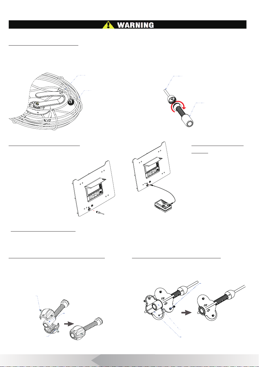
To r educe the risk of serious injury during use, follow these procedures for proper assembly.
1. Install Camera Head
Put the cable into the hook of the handle, (Figure 7.) Hold the cable connec tor in one hand, then scr ew the
camer a and x it on the cable tightly. (Figure 8.)
HOOK
CABLE
Figure 7. Cable reel in the case
2. Install aviation cable
Plug the cable into the socket of the panel and scre w
tightly. (Figure 9.)
CABLE
Figure 8. A ssembly/Disa ssembly Camer a
CAMERA HEAD
3. Install power
cable
Connect the po wer
cable to batt ery and
panel. (Figure 10.)
Fi gu re 10. Install po wer c able
Figure 9. Inst all avia tion cable
4. Install guide tting
Support Guide are designed to help position the camera tow ards the middle of the pipe. There are 2 kinds of
guides, choose guides properly per application requirement.
A. Installing 46 Support Guides.
Sleeve the camera heads with 46 Support guide.
( F i g u r e 11. )
Figur e 11. Ins tall 46 Suppor t Guides
B. Install 80 Support Guides.
Mount the 80 support guide onto the stainless st eel
camer a head. Then tighten the scr ew by screwdriver.
(F i gur e 12.)
Screw 2X
Camera Head
Support Guides
Fi gur e 12. Inst all 80 S upport Guides
5
Page 7
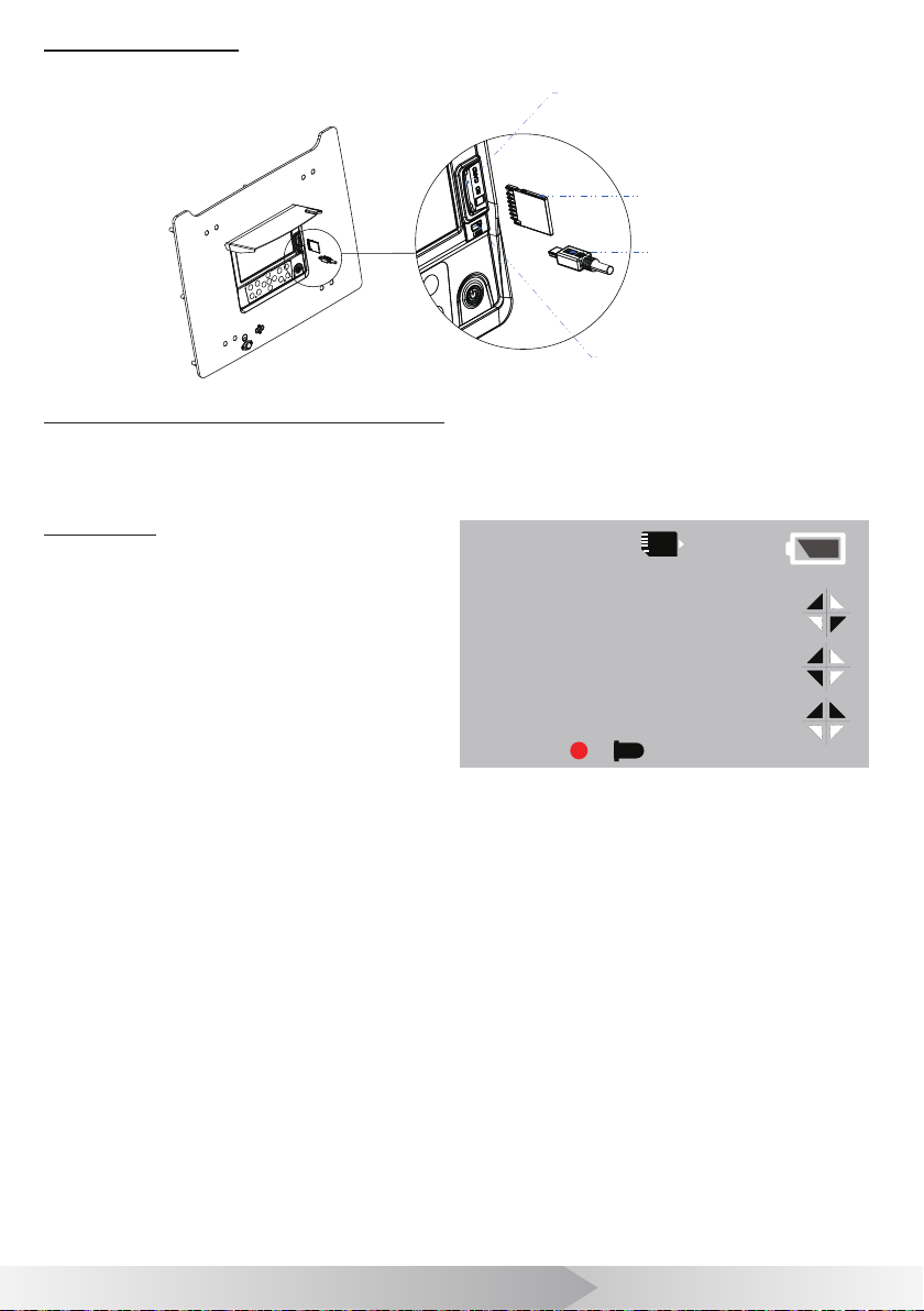
5. Install SD Card
(Fi g ur e 13. )
CARD SLOT
SD CARD
USB CABLE
USB SOCKET
Figure 13. Install SD Car d
6. Turn on the battery pack and DVR.
[ FUNCTION GUIDE AND OPERATING INSTRUCTIONS ]
DVR Icon
1. SD C a r d
2. Battery Le vel
3. Image Reverse
4. Image Reverse & Mirror
5. Image Mirr or
6. Timest amp
7. LED Brightness
8. Record
9. Met er Counter (optional function)
1.83m 6.0ft
9
SD
1
12:34:56
Figure 14. Screen icon Denition
2
3
4
678
5
6
Page 8

[ FUNCTION GUIDE ]
1. Live video
Press [ ] to turn on/off DVR to enter the live video mode, then press [ ] to ent er playback mode.
Press [ ] t o start/ st op recording.
Press [ ] to mirror or/and rever se the image.
Press [ ] adjust the brightness of camera LEDs.
Press [ ] to take a picture.
2. Video Option
Press [ ] to enter the video option menu. Press [ ] and [ ] to select items that you need, press [
] to conrm the selection. Press [ ] or [ ] to change the value. Press [ ] to save the setting.
Press [ ] to exit video option and save.
• Size D1 (720*576) / VGA (640*480) / QVGA (320*240)
• Video Seg: 10min/20min/ 30min/ 40min /OFF. Set 10-40min to restric t files lengt h and open cycle -c over. Elder files will be
covered by new les when SD card is full. Set OFF to close this function.
• Meter Count er: Reser ve f unction.
• Sound: Turn on/off the local sound in Video Rec ording.
• Timestamp: Enable/Disable time stamp on scr een.
3. Playback
Press [ ] the but ton to enter the playback, the user can browse, pr evie w and playback media les.
Press [ ] and [ ] to br ow se and select media les.
Press [ ] to conrm the selection and pr evie w media le. Press [ ] to preview the pr evious le. Press [
] to preview the next le. Press [ ] to playback video. Press [ ] t o ent er the play setting.
• Delete: Delete media les.
• Slide Show: 3sec/5sec/10sec. To set interval time of the slide shows.
• Protection: To protect important media les.
• Thumbnail: Browse 9 media les per page.
• File List: Browse 3 media les per page.
• LCD: LCD br ightness.
4. Playing Movie
[ ] Pause /Play movie, [ ] Stop play movie, [ ] R ewind, [ ] Forw ard, you can press [ ] to
set speed r ate of rewind/ f orward.
5. SETUP
Press [ ] to enter the preferenc es o f Record/Playback. Press [ ] enters Setup menu.
The f ollowing items ar e in the setup menu.
• Format: format SD car d.
• LCD: LCD br ightness.
• Language: English, German, French, Spanish, Italian, Chinese, Japanese, Russian, Por tuguese.
• Sys. Reset: Reset all setting.
• Light fr equency, 50Hz /60Hz, specifying your ambient light frequenc y.
• TV output: PAL/NTSC.
• Date input: To set date and
time.
At the Job Site
1. Always wear rubber gloves to operate the camera f or health and safety reasons. Properly positioning the
cable r eel will save time and strength to push out and in the cable, and minimize the r ate of equipment damage.
•
When pushing, the end of your stroke should be as close to the entr y as possible. Standing too far back with
an excess of cable between y our hands and the entry may cause the cable to f old on itself outside the entry
and damage the cable.
7
Page 9
•
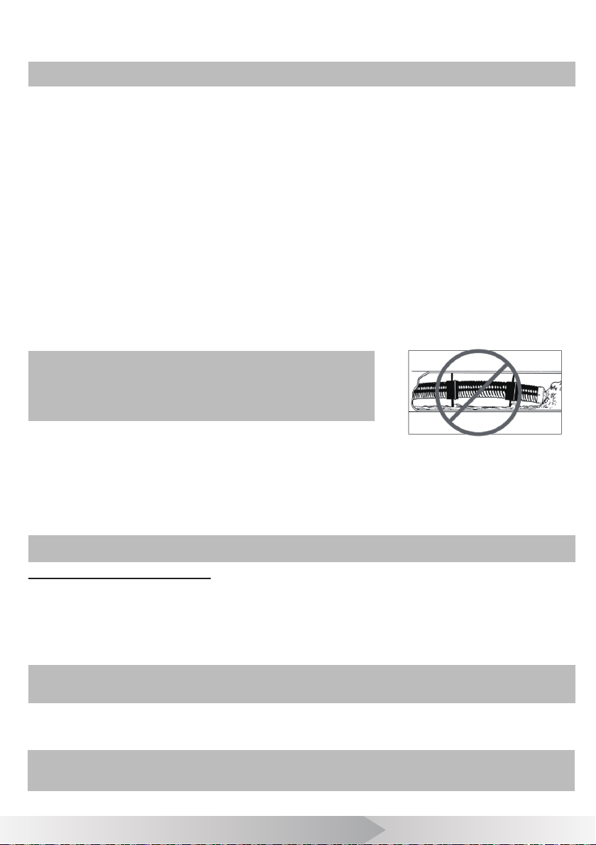
Try to keep the push cable aw ay fr om sharp edge of a pipe entr y bec ause this may cause damage. If the
camer a does not seem to go any farther,
if possible.
NOTE! Hands should be close to the line opening. DONOT catch the cable on the edge
of an entry and continue to push.
2. Alw ays try to run wat er down the pipe under going inspec tion. This will keep the system much cleaner, and
allow you to push noticeably f arther with less friction. If the water is prev enting you fr om seeing an area of
import ance, t emporarily turn it off.
3. When push the push cable through the pipeline by steady and slowly, a short distance entr y per time, keeps
the hands at the entrance, so that c an control the push cable and prevent it stuck, bent or scrat ch.
4. When inspecting a pipe, most of the time a slow steady push through the system works the best. At changes
in direction such as P-traps, Tee's, Y's, Elbows, etc. It is usually necessary to give a little extra push in the
bends. Back the camera head approximat ely 8" (20cm) fr om the bend, if necessary, and give it a quick push,
“popping” the camera through a turn, using the least amount of for ce required. Try to be as gentle as possible,
and do not hammer or snap the camera head through corners. Af t er some practice, y ou may learn that the best
way to inspect a section of pipe is to push the camer a through quickly. Then draw the camera back home slowly
and ev enly.
5. Mak e sure the sapphire window is clean prior t o entry. Some user s claim that a slight lm of detergent on the
lens minimizes the possibility of grease sticking to the port. If necessary, take advantage of any standing water
in the pipe to wash the f ront of the camer a b y jiggling it in the wat er.
6. When you place the camera head into the pipe r emember, as the materials o f pipe var y, it will be necessary
to ad just the light ing sett ings to ma ximize pictur e qualit y.
7. The system can travel through multiple 45 and 90 degree bends and wyes. Do not, however, try to f orc e it
through a P-tr ap or tee if there is a lar ge amount of r esistance.
NOTE! Do not try to use the camera head to clear
obstructions. This System is a diagnostic tool, not
a drain cleaner. Using the camera head to clear
obstructions could damage the camera head or cause
it to be caught in the obstruction.
8. Do not attempt to remove or st ores push cable on the reel solely by
turning the r eel it se lf. You can manually push or pull cable fr om the reel
and wind or unwind it.
9. If the camer a sits in a pipe, or an enclosed environment, heat will build-up. This may lead to the camera
head over heating which will cause fuz zy lines to appear on the monitor. In the event, this happens, turn of f the
system, remove the camer a f rom the pipe (or enclosed environment) and let the camera head cool for 10 to 15
minutes. Running wat er into the line will also help cool the camer a head. Alwa ys use the minimum illumination
required to maximize picture quality and to avoid excessive heat build-up.
NOTE! The camera head can get HOT! When nished with your inspection, or if taking a
prolonged break in the middle of the inspection, turn off the system.
DO NOT FORCE TO PUSH THE CAMERA!
Figure 15. Improper op eration
Try another entr y
Retrieving the push cable
1. Once the inspection has been completed, pull the push cable back with slow, steady force. Do not for ce the
push cable or exert ex cessive f orc e. This could damage the camera or push cable. The push c able may get hung
up while being re tr ieve d, and ma y nee d to be manipulat ed as did during insertion.
2. Once the inspection has been completed, pull the push cable back with slow, steady force. Do not for ce the
push cable or exert ex cessive f orc e. This could damage the camera or push cable. The push c able may get hung
up while being re tr ieve d, and ma y nee d to be manipulat ed as did during insertion.
Note! NEVER USE SOLVENTS to clean any part of the system. Substances like acetone
and other harsh chemicals can cause cracking of the camera ring, which could affect
waterproong.
3. Stor ing the push c able into the cable reel. One hand holds the push cable, the other hand close to the cable
wheel. Slowly and gently push the push cable slide via the hook o f the handle, cable reel will rotate and store
the push cable inside.
Note! The hands should be close to the cable wheel when storing the push cable. Push
the push cable a small piece every try. Push a long distance can cause the push cable
bend or broken.
8
Page 10

[ BATTERY PACK SAFETY AND USING GUIDE ]
Using safety
Read the f ollowing battery pr ecautions before using the bat ter y and charger, t o r educe the risk of electrical
shock.
1. Rechar ge batteries with accessor y char ging units.
2. Check the power units and battery pack every time before using the equipment, be sure no problem, use of
unauthorized par ts may result in electric al shock, re and/or serious personal injury or damage other instruments
and sy st em.
3. Never connec ts the car charger to any 24 volt cigarette lighter slot. It will harm the battery pack and DVR.
4. Do not short circuit, it may cause re, electrical shock.
5. Do not charge the bat ter y under r ain or w et conditions. Wat er entering the char ger will increase the risk of
electrical shock.
6. If the charger and batter y are damaged, do not use or stop to charge. It may cause electrical shock.
7. Don't disassemble the batter y and case of pow er adapter, only qualified repair person can repair and
maintenance.
8. Properly dispose of the battery. Exposure to high temperatures can cause the battery to explode. So do not
dispose of in a re. Some countries have regulations concerning battery disposal. Please follow all applicable
regulations.
9. Do not touch anything which out fr om batt ery, which would burn or damage the skin, once touches please
ush with water. If in eyes, immediately get medical help f ast.
Using Guide
Follow the s teps as belo w t o reduce the injury of the electric shock.
1. Plug the power adapter to the AC outlet, and inser t the other end into the DC inlet on t op of the battery
pack, char ging LED will be red during charging, will be turned to green when charged fully. If batt ery empty f or
a long term, it w ill pre-char ge the batt er y automatic ally in 10 minut es, and charging LED w ill be blinking in r ed.
2. Turn on the power of the battery pack, the bat ter y will supply the s ystem, the bat ter y level will be displayed
by the indicat or, each gr een LED indicators mean 25% per cent of the batt ery.
3. It needs about 8 hours to charge the battery fully. The bat ter y can charge online, charging and supplying of
work will not incr ease charging time s.
Tips
User can use a pow er adapt or or car char ger to charge the batter y pack. Also c an directly supply the system
without battery pack.
If no use in a long term, take a recharge per 3 month, to ensure the battery in normal working status.
9
Page 11

Optional
[ WIRELESS KEYBOARD OPERATION ]
The keyboard text writer is used to type characters with the wireless keyboard and display on screen. The
characters can be displayed in recor ded video or captured photo. It supports max. 384 charact ers and quick one
ke y hiding charac ters.
(
)
Text Input
1. Typing characters with wireless keyboard. Using arrow key to move cursor, backspace key to delete ,and
enter k ey to change a new line.
2. Esc key to hide or appear all characters.Ctrl + Del to delete all characters.
3. You c an type and edit char acters while recording, the typing and editing will be r ecor ded in the video les.
4. The typed charac ter s will be stored in memory.
Note: You have to change the wireless keyboard Receiver together when changing a
new keyboard.
Backstage Operation
You can press “F1” or “F2” key within 5 seconds af ter DVR monitor starts to enter F1 or F2 backst age operation.
1. The rst line is reserved for user to type company name, name of operator, phone number etc., and these
contents won’t be hid by pushing ESC button. You can edit the contents by using F1 key, and press Enter key to
save and exit.
2. Please re fer t o met er counter oper ation prior to this operation. Using F2 backgr ound key to select the unit
of length or the total length of push c able (this is designed in case the total length of push c able is changed).
When the “L=” flashes, press up or down arr ow key to select the unit of length, or select the correct total
length. Press enter key t o save and exit.
Set Meter Counter
1. Press the met er-zero button to set the meter to zero on screen display.
2. Change the unit of length or the total length of push cable, please ref er to ‘F2 backstage operation’
contents in the wireless keyboar d operation.
Note1: The deviation of MC will increase if the total length is not correct. You need
to select the correct total length to decrease the deviation. Use this function to change
the displayed total length when the push cable is cut off for more than 3 meters.
Note 2: Turn on the system before pulling out the push cable from the cable reel. It can
decrease the deviation of the MC.
10
Page 12

[Meter Counter User manual ]
2
1
(
)
Optional
Specications
Item Parameter
Display length Meter and Feet
Cable Length 20/30/40 meters (optional)
Ac cura cy 9cm/0.3Feet
Deviation ±0.7%
Counter R ange 0~40 meter s
Operating Temperatur e -10~50°C/ +14~+122°F
Operat ing Humidity 30%RH~90%RH
Storage Temperature -20~60°C/+4~ +14 0°F
Features
1. Meter Counter Set
2. R es et But t on
Operation
1. Connect the cable on the panel then turn on the scr een.
2. Meter will be displayed on screen when pulling out push cable.
3. Press the reset butt on to set zer o.
Note: Connect cable to panel before turning on screen in order to avoid error.
Optional
[ Text Writer User Manual ]
The Text Writer c an type in character s to display on screen and rec ord in video les. You can type and edit up
to 40 characters.
(
)
Figur e 16. M eter Co unter
Key Feature
1. Character key
• 26 English letters.
• 10 Ar abic numerals.
• 13 symbols.
2. Function key
Enter key, conrm typing.
Del key, delet e character.
Key, move the cursor to left.
Key, move the cursor to right.
Shif t key, switch English letter s and Arabic numerals.
Caps Lock k ey, switch capital letter s and small letters.
Type Operation
1. Turn on the scr een.
2. Make the Text Wr iter point to scr een then press character keys.
3. Press the same key again to select letters circularly. No operation or press other keys in 2 Seconds to conrm curr ent
charact ers.
4. Press REC key on DVR t o r ecord the Video with characters.
5. You can type and edit char ac ters while recording, the typing and editing will be r ecor ded in the video also.
Notes: Reboot the DVR will lose all characters on screen. The characters on screen
cannot be recorded on photos.
Fi gu r e 17. Tex t Wri ter
11
Page 13
Optional
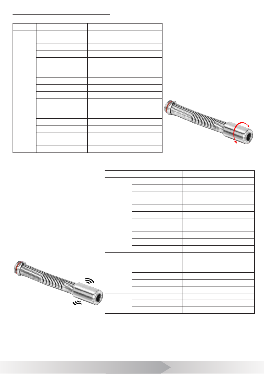
Camera C23MNS Specications
(
Type Item Parameter
Camera Size Φ23mm×45mm (Main body)
Camera Length 15 0mm (To t al )
Po wer Supply DC 9 ~15 V
Current Consume 55mA (LED OFF);110mA(LED ON)
Wat er-Pr oof 20m Water (Camer a x on Cable)
General
Shell Material 304# Stainless Steel
Lighting Built-in 12×LED(White)
Weight 150g(approx)
Operating Temperatur e -10~50°C/ +14~+122°F
Operat ing Humidity 30%RH~90%RH
Storage Temperature -20~60°C/+4~ +14 0°F
Sensor CMOS
TV-Line 420 TV-Line
Resolution 720×576
Image
Vie w Angle 12 0°
Focus Distance 20cm (appro x)
Depth-of -Field 100cm(appr ox)
Front Lens Sapphire
Camera C23MTO Specications
Type Item Parameter
General
Image
Transmit ter
Fi gu re 19
. Camera C23MTO
)
Fi gu re 18
. Camera C23MN S
Optional
(
Camera Size Φ23mm×45mm (Main body)
Camera Length 15 0m m(To tal)
Po wer Supply D C 9~15 V
Current Consume 70mA(LED OFF);125mA(LED ON)
Wat er-Pr oof 20m Water(Camera x on Cable)
Shell Material 304# Stainless Steel
Lighting Built -in 12×LED(Whit e)
Weight 150g(appr ox)
Operating Temperatur e -10~50°C/ +14~+122°F
Operat ing Humidity 30%RH~90%RH
Storage Temperature -20~60°C/+4~ +14 0°F
Sensor CMOS
TV-Line 480 TV-Line
Vie w Angle 120 °
Focus Distance 20cm (appr ox)
Depth-of -Field 100cm(approx)
Front Lens Sapphir e
Frequency 512 ±2Hz
Transmit Mode Const ant
Transmission Distance 5 met er under ground (max)
)
12
Page 14

[ OTHERS ]
Troubleshooting
Problem
Meter is not
ac cur ate
No Battery
level indicate
No ima ge
Can not input
Characters
The deviation
of MC mor e
than 0.5 %
FCC Statement
This device complies with part 15 of the FCC Rules. Oper ation is subject to the following two conditions:
1. This device may not cause harmful interfer ence.
2. This device must accept any inter f erenc e r eceived, including interf erence that may cause undesired operation.
Any changes or modif ication not expressly approved by the par ty r esponsible for compliance could void the
user's authorit y to operate the device.
CE
This product complies with standards including Low Voltage Device Directive 73/23/EEC;
EMC
Directive 89/ 336/EEC. It passed the subject tes ts by the authority concerned and is authorized to bear CE mark.
Probable fault
location
Knurled wheel slip Fit glassber cable into the guide solt and hook.
not set to zero Pr ess reset button to set zero.
No power completely To charge the bat tery
Fuse burned Change the fuse
Cable c onnection faulty
or loosely
Camera connec tor soiled Clean the camera connector
Wrong SD memory card Turu o ff power and r eplace SD car d
Wrong setting Enter the setup menu and select reset
The wireless keyboard
low battery
Wireless Keyboard or
Rec eiver f ault
select the wrong tot al
length
Pull out cable more than 3
meters bef ore turning on
the system.
Check cable connection, clean and r econnec t if necessar y
Chang batt ery
Check the Keyboard Receiver and the keyboard on a PC
Re-select the cor rect to tal length. You can press F2 key
when t he mac hine boot wit hin 5 s ec to enter bac kground to
select it.
Turn on the system bef ore pulling out the push cable from the
cable reel.
Solution
13
Page 15
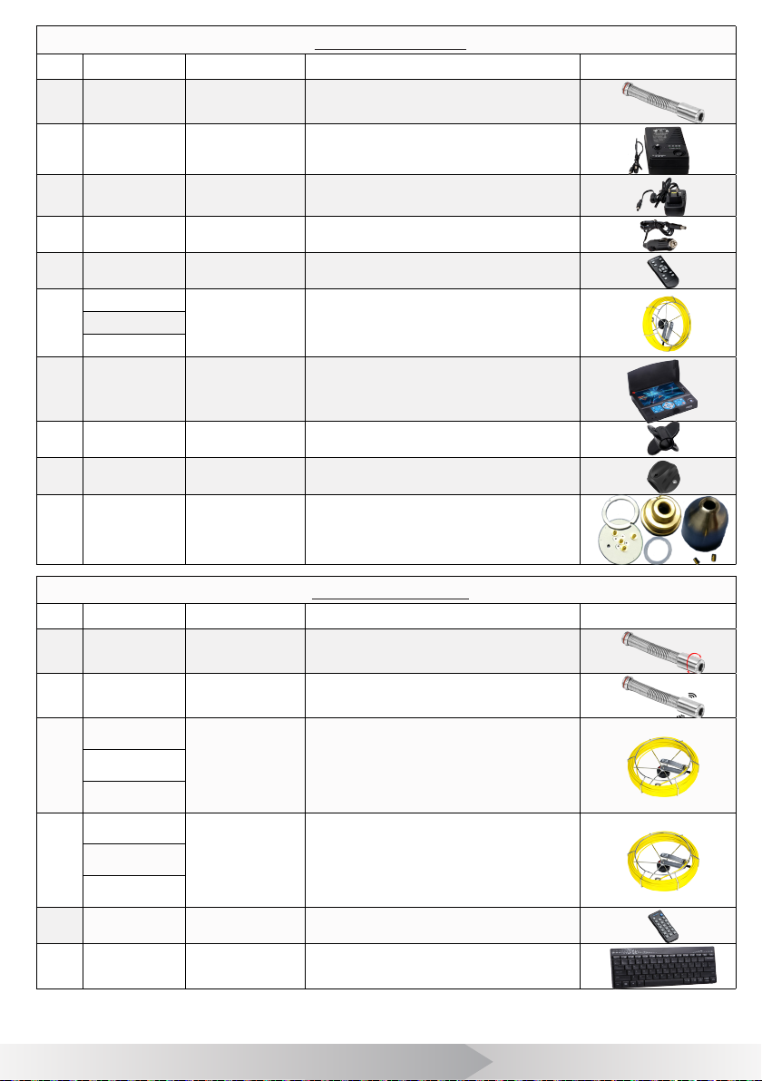
Part Number List
No. Part Number Part Name Specic ations Picture
1 C23MNO Camera head
2 2 -301 Batter y Pack 7.4V 6600mAh Battery
3 2 -312 Adaptor D C 12 V 1. 5 A A d a pt or
4 2-323 Car Charger DC 12V 2A Car Char ger
5 3 -4 12 Remote Contr ol 13 K ey R e m o t e C ont r o l
4- 5 01- 20
6
4-501-30
4- 5 01- 40
7 5 -6 12 DVR 7-inch Video Recorder, 14Key
8 8 -901 Guide 80 Suppor t Guide
9 8-923 Guide 46 Support Guide
10 9 -001 Maintenance The par ts for berglass Connector
Cable Wheel
Sony CCD 480TVL, Φ23×150mm,
120° Vie w A n g le
Rotatable reel contains
Φ5.2 mm c able.
20, 30, 40m length optional.
Optional Part List
No. Part Number Part Name Specic ations Picture
1 C23MNS Camer a head
2 C23MTO Camer a head
4-512 -2 0
3
4-512-30
4-512 -4 0
M2820U
4
M2830U
M2840U
5
6
3-423 Text Writer 20Key Text Writer
K7924K
Cable Wheel
Cable Wheel
Wireless
keyboard
CMOS 420TVL, Φ23×150mm,
120° View Angle with Self Leveling
CMOS 480TVL, Φ23×150mm,
120° View Angle with 512Hz Transmitter
Rotatable reel contains
Φ5.2 mm c able.
20, 30, 40m length opt ional.
Built -in Meter Count er
Rotatable reel contains
Φ5.2 mm c able.
20, 30, 40m length opt ional.
Built-in Meter Counter & Wireless Keyboard
Rec eiver
Wireless keyboard and receiver
14
Page 16

15
 Loading...