

Tuxedo TP9KACX, TP9KSCX Installation & Operation Manual
TP9KACX / TP9KSCX
Two-Post Clear Floor Lifts
(Asymmetric / Symmetric)
9,000 lbs. Capacity
(2,250 lbs. Max per Arm)
INSTALLATION & OPERATION
MANUAL
Jun 2017

IMPORTANT NOTES
READ THE INSTALLATION AND OPERATION MANUAL IN ITS ENTIRETY BEFORE
ATTEMPTING TO INSTALL THE LIFT.
• Do not install this lift on any surface other than concrete, conforming to minimum specifications.
• Do not install this lift over expansion joints or cracks. Check with building architect.
• Do not install this lift on a second floor with a basement beneath without written authorization from
building architect.
• Do not install this lift outdoors unless special consideration has been made to protect the power unit
from inclement weather conditions.
• A level floor is recommended for proper installation and operation. Concrete should be a minimum
of 4-1/4” thickness and 3,000 psi tensile strength with steal or fiber mesh reinforcement.
• The lift is intended to raise the entire body of the vehicle. Do not attempt to lift only part of the vehicle.
Improper use of this equipment could result in damage to the lift, yourself or other property.
• The lift is intended to lift vehicles only. It is not designed to lift any person or equipment containing
persons.
• Users of this equipment should be qualified, responsible and should follow the operation and safety
guidelines set forth in this manual.
• For specifications on concrete pads, please call for technical assistance.
• Improper installation can cause damage or injury. The Manufacturer will NOT assume liability for loss
or damage of any kind, expressed or implied, resulting from improper installation or use of this
product.
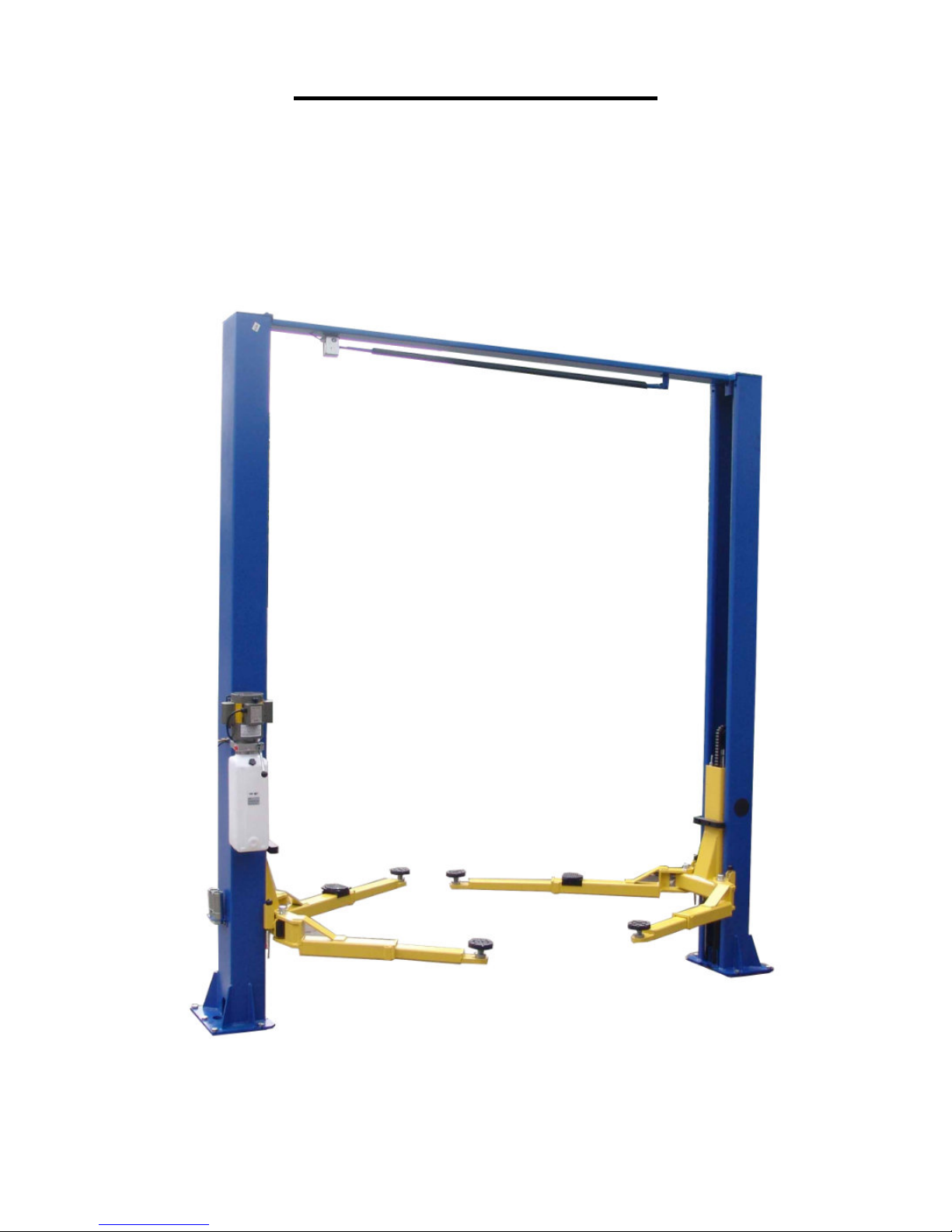
DEFINITION
Surface Mounted, Two-Post, Clear-Floor Lift w/ Overhead Beam, Hydraulic ‘chain-over’ Drive,
9,000 lbs. Capacity.
The name / model numbers are designated below:
• Model number TP9KACX - Asymmetric Swing Arms configuration
• Model number TP9KSCX - Symmetric Swing Arms configuration
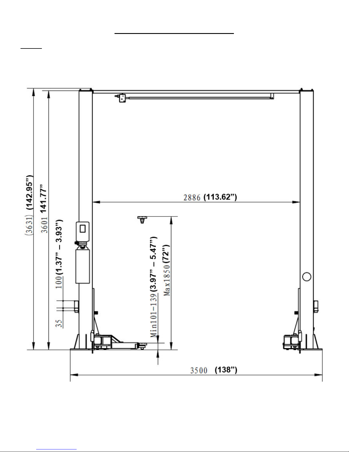
BASIC SPECIFICATIONS
Model Description
(Clear Floor)
TP9KACX Asymmetric 9,000 lbs. 50 Sec 143” 138” 72” 113-5/8”
TP9KSCX Symmetric 9,000 lbs. 50 Sec 143” 138” 72” 113-5/8”
Capacity Lifting Time Overall
Height
2
TP9KACX / TP9KSCX
Jan 2017
Overall
Width
Lifting
height
Between
Posts
PREPARATION
The installation of this lift is relatively simple and can be accomplished by 2 men in a few hours. The
following tools and equipment are needed:
• 12 quarts of Non-Detergent / Non-Foaming Hydraulic Oil - SAE-10, AW 32 or equivalent
• Chalk line and 12’ Tape Measure
• 4ft. Level
• Rotary Hammer Drill with 3/4” Masonry Drill Bit. (Core Drill Rebar Cutter also recommended)
• Hammer and Hex Key Wrench Set
• Metric Sockets and Open Wrench set - 13mm-30mm
• Medium Adjustable Wrench and Medium Pipe Wrench
• Crow Bar for Shim Installation and Medium Flat Screwdriver
• Locking, Needle Nose and Snap Ring Pliers
GENERAL INFORMATION
1. Carefully remove the crating and packing materials.
CAUTION! Be careful when cutting steel banding material as items may become loose and fall
causing personal harm or injury.
2. Identify the components and check for damage or shortages.
Please contact your distributor immediately, if any damages or shortages are discovered.
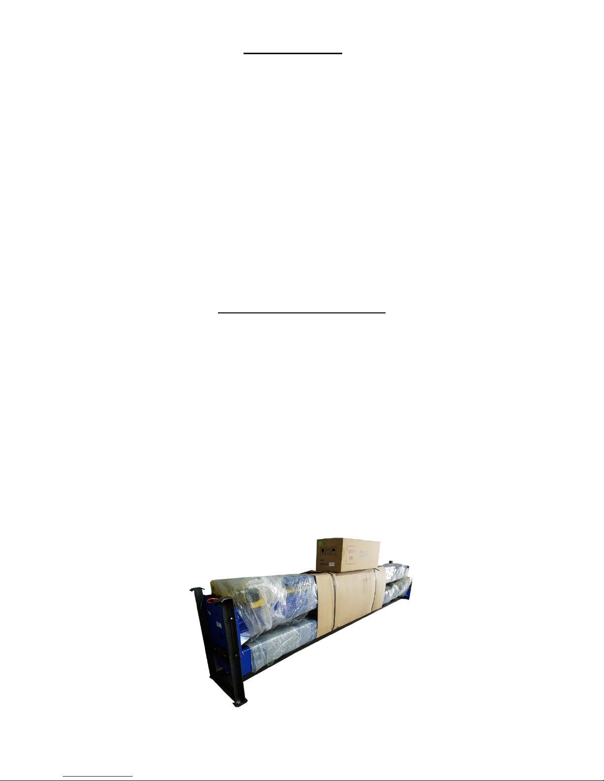
Packing:
• The lift assembly is packaged into two columns as one piece, as shown in (Fig.1).
• Every column comes with its cylinder, carriage, cables & chains, lifting arms, swivel pads, height
extensions, hoses and overhead beam with the hardware box located in one of the columns.
•
The electric-hydraulic motor pump is packaged separately and banded to top of lift.
Fig. 1
3
TP9KACX / TP9KSCX
Jan 2017
4
TP9KACX / TP9KSCX
Jan 2017
INSTALLATION INSTRUCTIONS
STEP 1: (Selecting Site) Before installing your new lift, check the following:
1. LIFT LOCATION: Always use architects plans when available. Check layout dimension against floor
plan requirements making sure that adequate space is available (Fig. 2, 2a, 2b & Fig. 3).
Fig. 2
(TP9KACX & TP9KSCX)
5
TP9KACX / TP9KSCX
Jan 2017
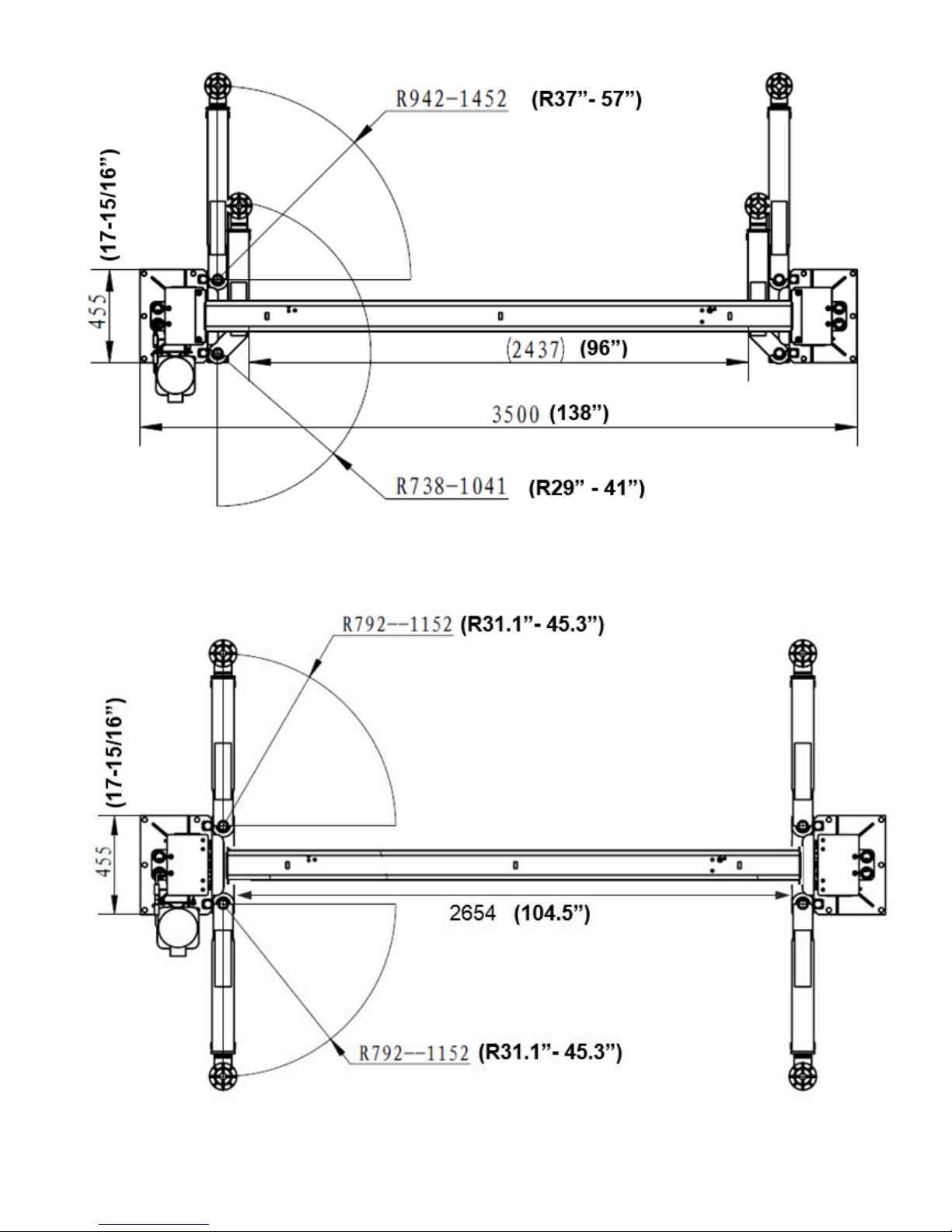
Fig. 2a
(TP9KACX - Asymmetric Lift)
Fig. 2b
(TP9KSCX - Symmetric Lift)
6
TP9KACX / TP9KSCX
Jan 2017
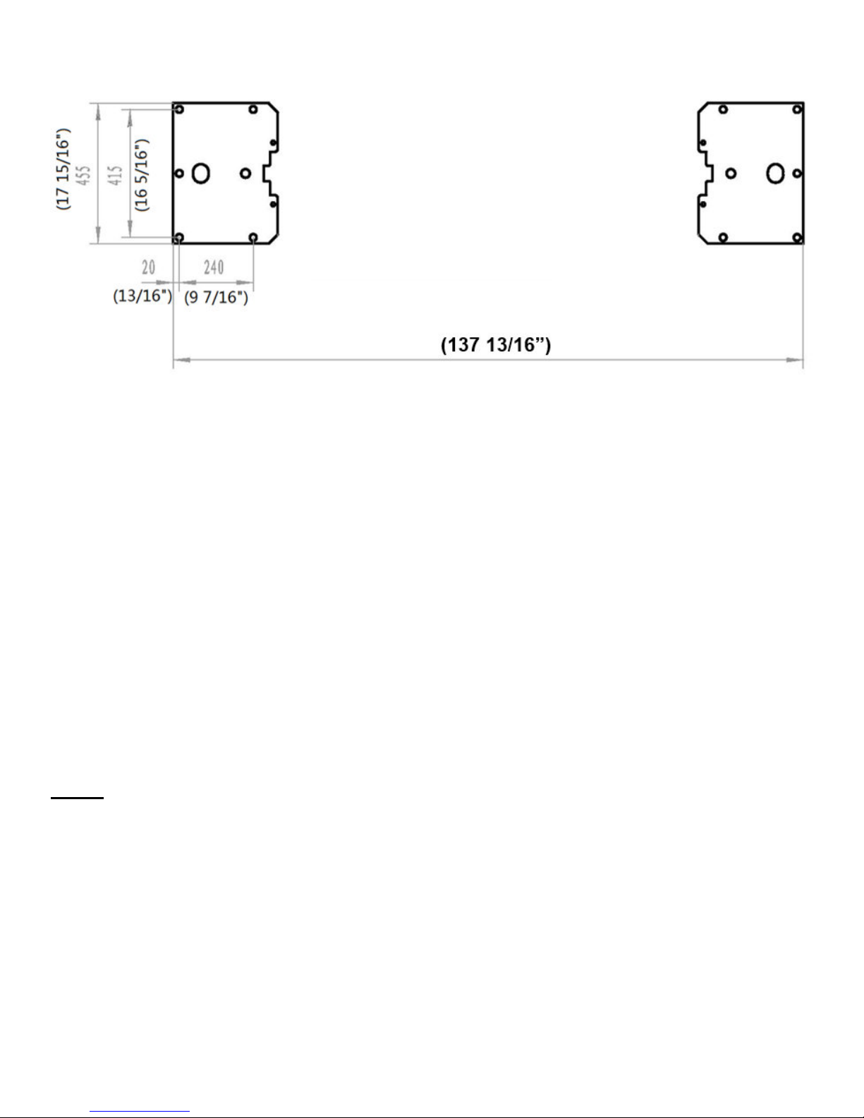
Fig. 3
(Column / Floor Layout)
2. OVERHEAD OBSTRUCTIONS: The area where the lift is located should be free of overhead
obstructions such as heaters, building supports, electrical lines, etc. (Fig 2.)
3. DEFECTIVE CONCRETE: Visually inspect the site where the lifts will be installed and check for
cracked or defective concrete. (Details on Page 4)
4. FLOOR REQUIREMENTS: The lift should be installed on a 3000 PSI concrete with minimum of 4-1/4”
thickness. The Floor should be level with-in gradients of ≦1/4” within area of the two columns = 138”
x 18”).
(See Details for Foundation Anchoring Requirements & Anchoring Tips on Page 4)
STEP 2: (Unloading & Unpacking)
1. After unloading the lift, place it near the intended installation location.
2. Remove the shipping bands and packing materials from the unit.
3. Remove the packing brackets and bolts holding the two columns together. (Do not discard bolts, they
may be used in the assembly of the lift)
4. Take out the lifting arms, swivel pads, height extensions, hardware box, hoses, covers, etc., from the
column. Check the quantity of each item with the parts list. If anything is missing, please contact your
dealer at once.
7
TP9KACX / TP9KSCX
Jan 2017
STEP 3: (Site Layout)
1. Determine which side will be the approach side.
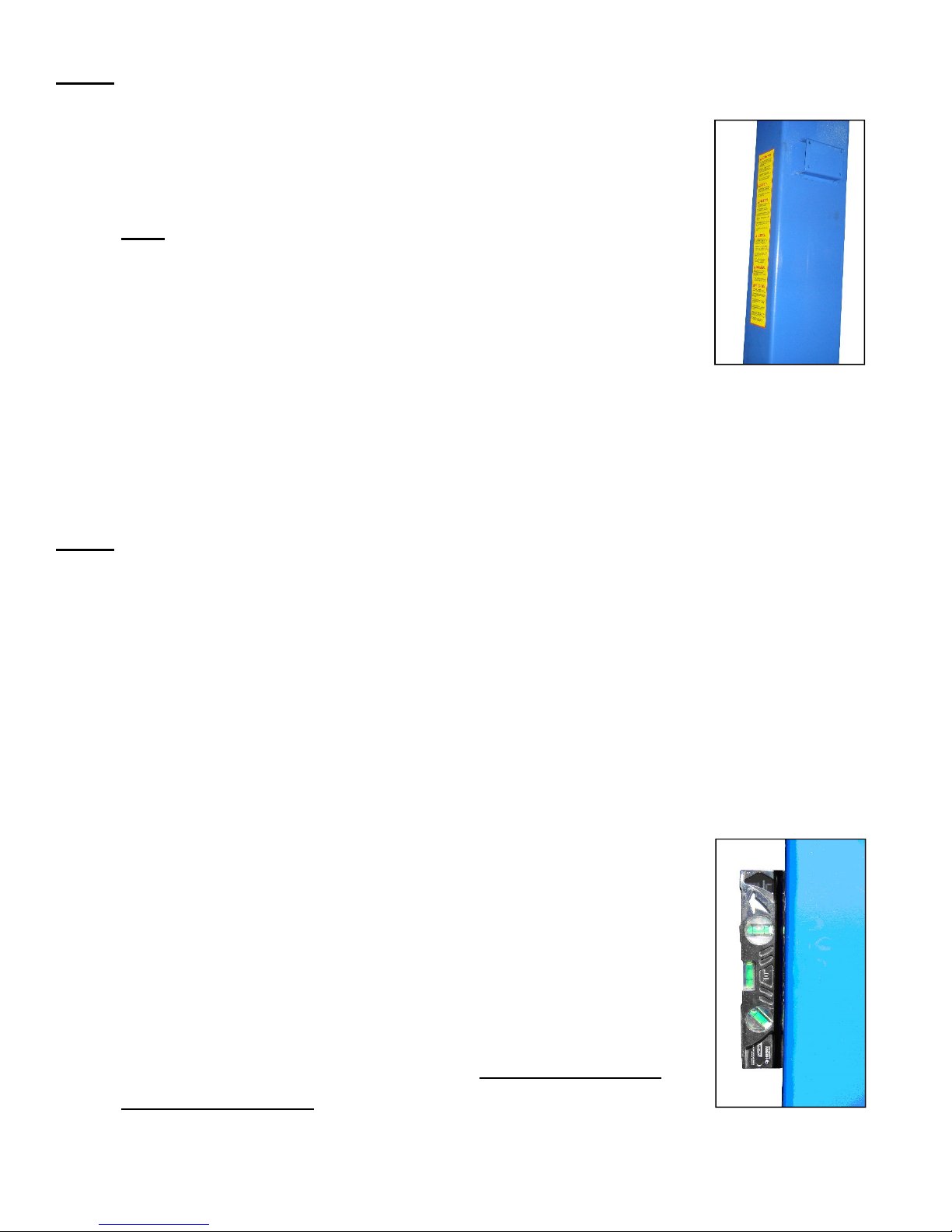
2. Now determine which side you prefer the power unit to be located on. The
MAIN column has the power-unit mounting bracket attached to the side, as
shown in (Fig. 4).
Note: the power unit column can be located on either side. It is helpful
to try and locate the power side on the driver side of the vehicle when
loaded on the lift, in order to save steps during operation.
3. Once a location is determined, use a carpenter’s chalk line to layout a grid
for the post locations. (See Fig. 3)
Fig. 4
4. After the post locations are marked, use a chalk or crayon to make an outline of the posts on the floor
at each location using the post base plates as a template.
5. Double check all dimensions and make sure that the layout is perfectly square.
STEP 4: (Installing MAIN COLUMN w/ Power Unit Bracket)
1. Before proceeding, double check measurements and make certain that the bases of each column are
square and aligned with the chalk line.
2. Ensure Top Cap is pre-installed to the top of the Main column. Raise the column to a vertical position.
3. Using the base plate on the MAIN column as a guide, drill each anchor hole into concrete using a
rotary hammer drill and 3/4” concrete drill-bit. To assure full holding power, do not ream the hole or
allow the drill to wobble. (See Anchoring Details on Page 4)
4. After drilling, remove dust thoroughly from each hole using compressed air and/or wire brush. Make
certain that the column remains aligned with the chalk line during this process.
5.
Assemble the washers and nuts on the anchors then tap into each hole with a block of wood or rubber
hammer until the washer rests against the base plate. Be sure that if shimming
is required that enough threads are left exposed.
6. Using a level, check column plumb for every side (Fig. 5). If shimming is
required, use supplied Shim stock or 3/4” washers, placing shims as close
as possible to the hole locations. This will prevent bending column bases.
7. With the shims and anchor bolts in place, tighten by securing the nut to
the base then turning 2-3 full turns clockwise. Ensure anchor bolts are
tightened to a minimum of 130 ft-lbs. of torque. DO NOT use an impact
wrench for this procedure.
8
TP9KACX / TP9KSCX
Jan 2017
Fig. 5
 Loading...