

SP-6K-SS
CAPACITY 6,000LB
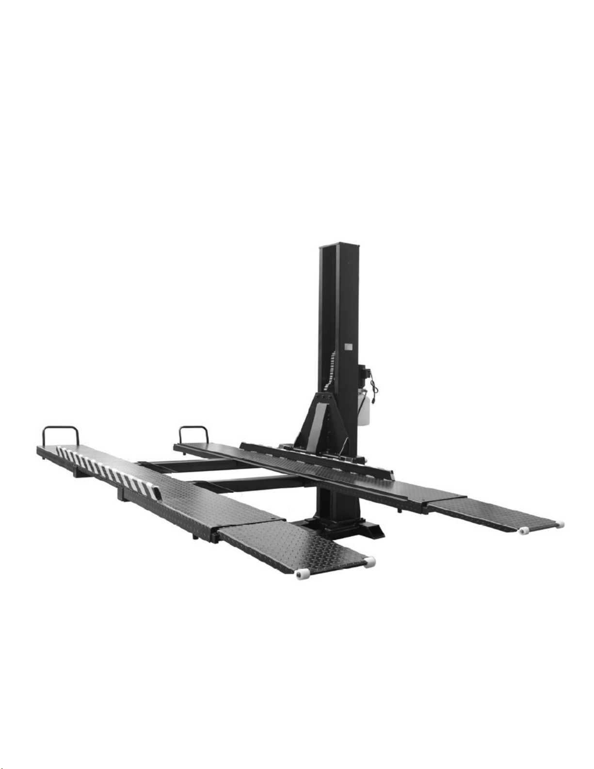
Single Post Storage Lift
INSTALLATION & OPERATING INSTRUCTIONS
Aug. 2019

1. GENERAL INFORMATION
1.1 SPECIFICATIONS
Specifications SP-6K-SS
Capacity 6,000 lbs.
Width Overall (pump mounted on back) 110-7/16”
Width Overall (pump mounted on side) 106-5/16”
Height Overall 110-1/4”
Length Overall 185-13/16”
Undercar clearance 76-15/16”
Drive Over Base Ramp Height 3”
Runway Width 18-7/8”
Runway Length 151–15/16”
Clearance Between Runways 39-3/8” – 42-1/2”
Approach Ramp Length 30-3/4”
Power Supply 110 VAC, 1PH, 20 Amp
2
Aug. 2019
SP-6K-SS
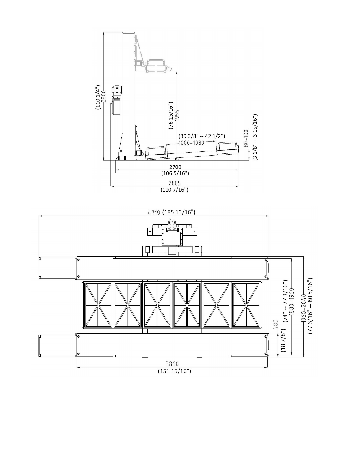
1.2 DIMENSIONS ( mm / inch)
(
Shown with optional
Drip Trays)
Fig. 1
3
Aug. 2019
SP-6K-SS
IMPORTANT!
Be sure to read the operating instructions before operating
Getting Ready
Make sure you have made all necessary measurements to assure that your lift will fit in your garage and
accommodate the two cars you intend to park with it. Make sure you have enough clearance at the top, and
enough width to allow parking a third car on the non-lift side. It is useful to chalk the outlines of the lift on your
garage floor, using the manufacturer’s dimensions, to see how the lift will fit. Knowing where the lift will sit the
base plate, which is the first step in the assembly process, will help to determine the location of the power
supply that is required to operate this lift.
Enlist the services of a qualified electrician to provide appropriate electrical service to the garage and make
sure he knows what the circuit requirements are. Seek his advice on receptacle and plug configurations that
will work.
Make sure you have someone to help you. The pieces of this lift are big, heavy, and cumbersome. It is
possible for two people to install this lift if they have the appropriate lifting and handling equipment, but it is
definitely easier and faster if there are several people available to help manhandle the pieces into place. As
with any activities involving big heavy materials, safety must be uppermost in your mind. This lift is more
difficult to install than some of our other units because of its one-post design, but this very design makes it
extremely effective for residential garage use. With proper preparation and installation, you will be very pleased
with this lift.
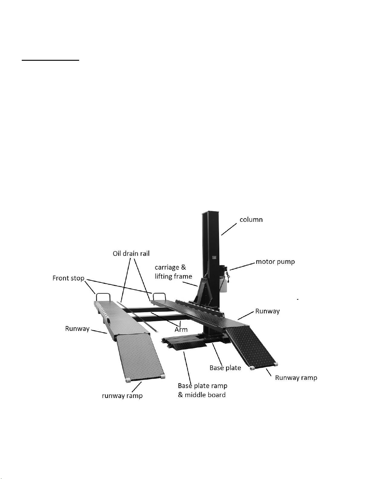
Fig. 2
Major Lift Components
4
Aug. 2019
SP-6K-SS

Required Tools
• Fork Lift to unload lift on delivery
• Fork Lift and/or engine hoist for moving pieces and positioning lift column. You will also need a ten-foot
length of 3/8” chain
• Metric wrenches and sockets with ratchet
• Adjustable wrench
• Small crowbar or large screwdriver for aligning bolt holes
• Concrete hammer drill with a new ¾” concrete bit
• Pliers
• Flat blade screwdriver and Philips screwdriver.
• Hydraulic floor jack on wheels or bottle jack, (for positioning pieces)
• 1-1/8" Socket & Extension
• 12mm Hex Socket
• Tin Snips
• 12 quarts of Non-Detergent / Non-Foaming Hydraulic Oil - SAE-10, AW 32 or equivalent
Optional Tools
• Fence stretcher, for pulling ramps onto lift arms
(May be helpful, depending on specific installation)
Floor Requirements
• The lift should be installed on a 3000 PSI concrete with little gradients.
• Thickness of concrete: ≥ 6 inch (150 mm).
Receiving & Handling
• When you receive your lift, it will come banded in one large package, and you will need a forklift to
unload it.
5
Aug. 2019
SP-6K-SS
Installation
You will need common hand tools that most homeowners have, like a hammer, screwdrivers and pliers. But
in addition, you will need some tools that are not common. Each installation is somewhat different, and
depends on how much room you have to work around the lift. Here is a chronological sequence of
installation steps, with the associated tools.
1. Unloading Lift
You’ll need a forklift that can handle about 2500 to 3000 pounds and operate on a smooth surface. They can
be rented by the day from many tool rental companies.
2. Un-banding Lift
The steel bands which secure the lift parts to the pallets are heavy duty. You’ll need a pair of metal shears or
tin snips to cut the bands. Be very careful when doing this because the bands will tend to fly apart when they
are cut, and the heavy lift parts may shift when freed from the bands. Stand to the side of the bands when you
cut them, and use gloves when removing the cut bands because they have sharp edges.
3. Moving Pieces
You can move the pieces to the garage with the forklift. Some of the smaller pieces can be moved by two or
more people carrying them, but the base plate, the lifting column, the arms and the runways will probably
require the forklift. A piece of 3/8” chain 10 feet long will be useful for moving heavy pieces by wrapping around
the pieces and the forks of the forklift or the engine hoist hook, if that’s what you’re using.
4. Installing Steps
STEP 1
The first piece to be positioned is the base plate. Place it on the garage floor as close to its final position as
possible. After the base plate is in place, you’ll fix it on the ground by anchors. Or, it may be anchored after
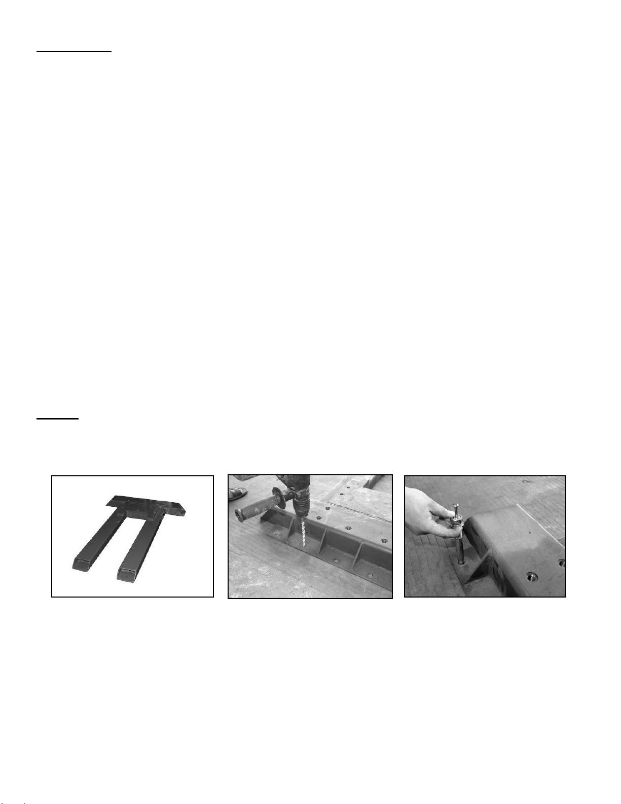
everything is done. (Fig.3 A, B, C)
Fig. 3
A, B, C (Anchoring Base Plate)
6
Aug. 2019
SP-6K-SS

STEP 2
The next major piece is the lift column. It will have the carriage unit, the hydraulic cylinder and chain assembly,
and safety latch cable already assembled in it.
Pick column up from horizontal position by a forklift or an engine hoist. Carefully lift it vertically high enough to
set the column on the base plate and maneuver it around to line up the mounting holes. The column is easier
to maneuver when vertical on the base plate. If possible, do not remove the straps from the column until you
have got the mounting bolts started into the base plate. (Fig.4 A, B, C, D)
Fig. 4
A, B, C, D (Set-Up Column-1)
After you’ve put the column into position, you’ll bolt it to the base plate. You’ll need a wrench or a socket with a
ratchet to tighten these bolts.
In order to make the column be vertical when car is loaded, shim plates have been welded to the bottom of the
column. The optimal tilting degree is between 0.5 and 1.0 (Fig. 5 A, B, C).
Fig. 5
A, B, C (Set-Up Column-2)
7
Aug. 2019
SP-6K-SS

STEP 3
Before mounting motor pump, first mount the bracket on the side you preferred (Right or Left or Back).
Then mount the motor pump on the back of column. Fix it using bolts and nuts. Connect the hose from the
cylinder to the motor pump. (Fig.6 A, B, C) The hose has different fittings on each end. So make sure you
match up the end of the hose with the cylinder. There is an O-ring on the end of the cylinder tube. Make sure
these fittings are tight.
Fig. 6
A, B, C, D, E (Motor Pump & Hose)
Fill the tank with hydraulic oil (about 6 Liter). It is suggested to be AW 32/46 Non-Detergent Non-Foaming
Anti-Wear Hydraulic Oil (SAE-10).
Now you need to get the motor pump with the correct power connection. Your 110V pump does come with a
short cord attached to the motor. But because it may be not long enough and there are so many receptacle
variations, you will need a proper extension cord and/or to install a plug on the end of the cord. If you are not
sure the cord size and which plug to use, consult your electrician. And the motor running direction should be
the same as the indication on it.
STEP 4
The next task is to position the lifting frame on the carriage with hex socket bolts. (Fig.8 A & B) A hydraulic
floor jack or bottle jack is recommended to assist in aligning mounting holes. Tighten all the bolts securely.
Fig. 8
A & B (Lifting Frame)
8
Aug. 2019
SP-6K-SS

STEP 5
Position the two lift arms to the lifting frame (Fig.9 A). In order to make the runway platforms horizontal while
car is loaded, install the arms as follows:
First, lift up the far end of the arms with hydraulic jack to 3-15/16” (100mm) (Fig.9 B & C). Then tighten the
back side two screws and front one screw (Fig.9 D & E). Use the lock-nut to secure adjustments.
A B C
D E F G
Fig. 9
A, B, C, D, E, F, G (Setting-Up Arms)
STEP 6
Install the runways on the lifting arms. If they are hard to move, you can use a chain and a fence-stretcher to
help maneuver them. Position the runway platforms according to the fixing holes on the arms. Bolt the runways
to the lifting arms with the provided bolts. (Fig.10 A, B, C)
Fig. 10
A, B, C (Runway Attachment To Arms)
9
Aug. 2019
SP-6K-SS

STEP 7
Attach drive-on ramps to end of runway platforms, along with ramp supports, according to the driving direction.
Ensure Circlips are properly installed into slots on pivot pins. (Fig.11 A, B, C)
A, B, C (Ramps & Support Brackets)
Fig. 11
STEP 8
Put on the wheel stop at the other end of the runway (Fig. 12). Bolt the ground ramp fixing chip on the base
plate. Then put on the ground ramps and middle spacer. (Figs. 13, 14)
Figs.12, 13 & 14
(Wheel Stops, Ground Ramps & Middle Spacer)
Re-check to ensure all Nuts, Bolts & Fasteners are securely tightened.
The lift is now ready for testing.
10
Aug. 2019
SP-6K-SS

OPERATING INSTRUCTIONS
The lift is very simple to operate. Turn on the power
supply first. Then press and hold the START button
on the motor to activate it. The motor operates an
internal pump that forces hydraulic oil into the lift
cylinder, which extends the roller chain and raises the
lift. (Fig.18)
As the lift rises, an internal safety latch will pass over the
steel stops (rectangular latch blocks which protrude from
the back, inside of the lift column), and you will hear
“clanks” as it does so. This sound is normal, and
indicates that the safety latch is passing over the stops
properly. Release the START button when the lift has
reached its desired position. For safety, every time it is
suggested to lock the lift by pressing down the
RELEASE handle, until the lift rests on the latch block.
Fig. 18
Start Button & Release Handle on Power Unit
To Lower Lift:
You first need to raise up the lift a little by pressing down the START button, if lift is in the raised locked
position. Then pull the Lock Release Cable (one time) to release the latch. After that, press down and hold
the RELEASE handle. The lift will lower down by gravity. No extra power is required to lower the lift.
After the installation is complete, before the first time application, raise the lift without load about three feet
high and then lower it to floor. Repeat this process for two or three times. And then top off the hydraulic oil
reservoir again, if necessary. This assures that hydraulic oil is distributed everywhere in the system that it
needs to be.
NOTE: Only top off the reservoir when the lift is in the lowest position. If you fill the reservoir in a
raised position, there will be too much hydraulic oil in the system when the lift is lowered, which the oil
will squirt out of the reservoir!!
11
Aug. 2019
SP-6K-SS

RAISING A VEHICLE
Drive the vehicle onto the platform through ramps until it is about centered. Set the parking brake.
Depress the START button on power unit and the vehicle will rise. Raise the vehicle until it’s near the
ceiling of the garage.
WARNING!!
BE CAREFUL NOT TO RAISE THE VEHICLE SO HIGH THAT IT STRIKES THE CEILING! MAKE SURE
ANTENNAS ARE REMOVED, IF NECESSARY. ALSO BE AWARE OF ANYTHING THAT PROTRUDES
FROM THE CEILING, LIKE LIGHTBULBS, GARAGE DOOR OPENERS OR DOOR TRACKS. IT IS VERY
HELPFUL IF YOU HAVE A “SPOTTER” ON A LADDER TO TELL YOU WHEN YOU ARE NEAR THE
CEILING FOR THE FIRST LIFT!
Fig.19
A & B Ramp & Ramp Support
In order to maximize the height underneath the platforms, the ramp support shall be pulled backwards. The ramp
rests on the support as in Fig.19 A. Before loading or unloading the vehicle on the platform, the ramp support shall
be pushed forward to allow for ramps for pivot down, as shown in Fig.19 B.
12
Aug. 2019
SP-6K-SS

OPTIONAL ACCESSORIES
The SP-6K-SS Lift has the ability to add Drip Trays between the Runways to assist in preventing any
vehicle oil and/or debris from falling on the floor or another vehicle parked under the runways.
NOTE: Drip Tray Rails are included with every SP-6K-SS Lift regardless if optional Drip Trays are
applied or not. If Drip Trays are not to be used, it is not required to install the support Rails.
IMPORTANT!
Based on how the Runways are installed, in either the ‘narrow or wide’ position will determine the specific
width size of ‘optional’ Drip Trays required to be ordered for the SP-6K-SS Lift. (See details below)
• ‘Narrow’ Runway Position: (P/N: FP9KDX-DT) - Drip Tray - 39"W
• ‘Wide’ Runway Position: (P/N: FP8K-DS/DX-XLT-DT) - Drip Tray - 42"W
Installation for Drip Tray Rails & Drip Trays
1. Locate and install Drip Tray support Rails to inside of Runways, using the #12 self-tapping screws
provided (Fig.15).
2. Place Drip Tray(s) on top of support Rails (Fig.16).
Fig.15 Fig.16
13
Aug. 2019
SP-6K-SS

SP-6K-SS
Exploded View (A)
14
Aug. 2019
SP-6K-SS

SP-6K-SS
Exploded View (B)
15
Aug. 2019
SP-6K-SS

SP-6K-SS Parts list
ITEM
CODE
DESCRIPTION
QTY
1 SP-6K-SS-001 DJ05-01000-000 Base Plate 1
2 SP-6K-SS-002
3 SP-6K-SS-003
3-1 SP-6K-SS-003.1
4 SP-6K-SS-004
5 SP-6K-SS-005
6 SP-6K-SS-006
7 SP-6K-SS-007
8a-1 SP-6K-SS-008A.1 DJ05-00005-D00 * Drip Tray, End Rail 4
8a-2 SP-6K-SS-008A.2 DJ05-00021-D00 * Drip Tray, Middle Rail 2
9 SP-6K-SS-009
10 SP-6K-SS-010
11a SP-6K-SS-011A
12 SP-6K-SS-012
13 SP-6K-SS-013
13-4 SP-6K-SS-013.4
13-5 SP-6K-SS-013.5
13-6 SP-6K-SS-013.6
13-7 SP-6K-SS-013.7
13-8 SP-6K-SS-013.8
13-9 SP-6K-SS-013.9
13-10 SP-6K-SS-013.10
13-11 SP-6K-SS-013.11
13-12 SP-6K-SS-013.12 DJ01-21005-M00 Piston 1
13-13 SP-6K-SS-013.13 DJ01-21006-M00 Nut 2
13-1 SP-6K-SS-013.1
13-2 SP-6K-SS-013.2
13-3 SP-6K-SS-013.3
13-14 SP-6K-SS-013.14 DJ01-00031-M00 Straight Connector 1
13-15 SP-6K-SS-013.15 DJ01-00030-M00 Throttle Washer 1
13-16 SP-6K-SS-013.16
13-17 SP-6K-SS-013.17
13-18 SP-6K-SS-013.18
13-19 SP-6K-SS-013.19
13-20 SP-6K-SS-013.20 DJ01-00014-M00 Roller 1
13-21 SP-6K-SS-013.21
13-22 SP-6K-SS-013.22
13-23 SP-6K-SS-013.23 DJ01-00021-M00 Hose 1
13-24 SP-6K-SS-013.24
14 SP-6K-SS-014
15 SP-6K-SS-015
16 SP-6K-SS-016
17 SP-6K-SS-017
18 SP-6K-SS-018
20 SP-6K-SS-020
21 SP-6K-SS-021
22 SP-6K-SS-022
23 SP-6K-SS-023
24 SP-6K-SS-024
25 SP-6K-SS-025
26 SP-6K-SS-026
27 SP-6K-SS-027
29 SP-6K-SS-029
30 SP-6K-SS-030
DJ05-10000-000 Anchor Bolt, 3/4” x 5.5” 10
5105-16050-000 Bolt, M16x x50mm 10
5301-00020-000 Flat Washer, D20 10
DJ05-02000-000 Column 1
5105-06030-000 Screw, M6x x30mm 4
DJ01-00005-M00 Upper Cover 1
5101-20040-000 Bolt, M20 x 40mm 12
5105-06025-000 Screw, M6 x 25mm 12
5107-06015-000 Screw, M6 x 15mm 4
DJ05-00001-000 4” Front Stop-A 2
DJ05-03000-A00 Platform 2
DJ01-13000-000 Cylinder 1
5906-00030-000 Dust Ring 1
DJ01-21002-M00 Guide Ring 1
DJ05-13002-000 Piston Bar 1
DJ01-21003-M00 Sheave 1
5901-00030-000 O-Ring 1
DJ01-21004-M00 Guide Belt 1
5901-00066-000 O-Ring 1
5905-00065-000 U-Ring 1
5205-00024-000 Thin Nut 1
DJ01-00013-M00 Round Nut 2
DJ01-20000-M00 Roller Seat 1
5309-00010-000 Circlip, D10 1
5603-00016-000 Combined Seal, D16 1
DJ01-13100-000 Cylinder Body 1
DJ01-12002-000 Roller Pin 1
5303-00024-000 Spring Washer 1
5901-00006-000 O-Ring 1
SJ01-12001-000 Angle Connector 1
DJ05-11000-000 Chain 1
DJ01-00004-M00 Chain Pin 2
5105-16060-000 Bolt, M16 x 60mm 2
5303-00016-000 Spring Washer, D16 21
DJ01-00001-M00 Chain Block (down) 1
5201-00020-000 Nut, M20 12
DJ01-00003-M00 Chain Block (upper) 1
5404-03020-000 Split Pin 4
DJ05-09000-000 Ramp 2
DJ05-00004-000 Nylon Roller 4
5304-00020-000 Circlip 4
DJ01-12000-M00 Carriage 1
5206-00030-000 Lock Nut, M30 x 1.5mm 1
DJ01-13002-M00 Lock Tongue 1
5206-00010-000 Lock Nut, M10 1
16
Aug. 2019
SP-6K-SS

31 SP-6K-SS-031
33 SP-6K-SS-033
34 SP-6K-SS-034
35 SP-6K-SS-035
36 SP-6K-SS-036
37 SP-6K-SS-037
38 SP-6K-SS-038
39 SP-6K-SS-039
40 SP-6K-SS-040
41 SP-6K-SS-041
42 SP-6K-SS-042
43 SP-6K-SS-043
44 SP-6K-SS-044
45 SP-6K-SS-045
46 SP-6K-SS-046
47 SP-6K-SS-047
48 SP-6K-SS-048
49 SP-6K-SS-049
50 SP-6K-SS-050
51 SP-6K-SS-051
52 SP-6K-SS-052
53 SP-6K-SS-053
54 SP-6K-SS-054
55 SP-6K-SS-055
56 SP-6K-SS-056
57 SP-6K-SS-057
59 SP-6K-SS-059
60 SP-6K-SS-060
61 SP-6K-SS-061
62 SP-6K-SS-062
63 SP-6K-SS-063
64 SP-6K-SS-064
65 SP-6K-SS-065
66 SP-6K-SS-066
67 SP-6K-SS-067
68 PU-110V-L-K 110V Power Unit 1
69 SP-6K-SS-069
70 SP-6K-SS-070
71 SP-6K-SS-071
72 SP-6K-SS-072
73 SP-6K-SS-073
DJ01-13003-M00 Release Cable 1
DJ01-13001-M00 Safety Latch 1
SJ01-07007-000 Spring 1
DJ01-00029-M00 Top, Nylon Block 4
DJ01-00028-M00 Side, Nylon block 8
DJ01-00027-M00 Block Frame 4
DJ05-01500-000 Middle Ramp Spacer 1
5105-06015-000 Screw, M6 x 15mm 2
5303-00006-000 Spring Washer, D6 14
5301-00006-000 Flat Washer, D6 18
DJ05-06100-000 Cable Holder 1
DJ05-06200-000 Lifting Frame 1
5105-16040-000 Bolt, M16 x 40mm 9
5105-12040-000 Screw, M12 x 40mm 8
DJ05-05000-000 Right Arm 1
5301-00012-000 Flat Washer, D12 8
5303-00012-000 Spring Washer 8
DJ05-04000-000 Left Arm 1
DJ01-00020-M00 Hook 6
DJ05-01400-000 Ramp 2
DJ05-14000-000 Ramp Support Bracket 2
DJ05-00003-000 Ramp Shaft Pin 2
5304-00016-000 Circlip, D16 4
5301-00010-000 Flat Washer, D10 4
5303-00010-000 Spring Washer, D10 4
5201-00010-000 Nut, M10 4
DJ01-00022-M00 Shim 10
5206-00020-000 Lock Nut, M20 1
5206-00016-000 Lock Nut, M16 2
5201-00008-000 Nut, M8 4
5303-00008-000 Spring Washer, D8 8
5301-00008-000 Flat Washer, D8 8
DJ05-00020-000 Motor Mount Bracket 1
5302-00008-000 Large Flat Washer, D8 4
5101-08020-000 Bolt, M8 x 20mm 4
5101-08025-000 Bolt, M8 x 25mm 4
DJ02-00027-000 Cylinder Plate 1
5101-08030-000 Bolt, M8 x 30mm 1
5110-04010-000 Screw, M4 x 10mm 24
2649-ZG003-000 * Self-Tap Screw, #12 x 3/4” 12
*
Indicates optional installation, if not using optional Drip Trays
17
Aug. 2019
SP-6K-SS

POWER UNIT PRIMING
WARNING!! Failure to properly relieve pressure in the following steps can cause injury to personnel.
IMPORTANT
POWER UNIT PRIMING PROCEDURE
THE PROBLEM: Power unit runs fine but will not pump any fluid.
Step 1 – Locate the check valve. It is the plug to the left of the lowering valve.
Step 2 – Using a Hex wrench and shop towel – with shop towel in place to catch fluid – loosen the
check valve plug by approximately 2-½ turns and allow fluid to bleed off.
Step 3 – Push the START button for one second, then release for three seconds. Repeat these
steps until unit starts pumping fluid.
Step 4 – Tighten the check valve plug.
YOUR POWER UNIT SHOULD NOW BE PRIMED
18
Aug. 2019
SP-6K-SS

LIMITED WARRANTY
Structural Warranty:
The following parts and structural components carry a five year warranty:
Columns Arms Uprights Swivel Pins
Legs Carriages Overhead Beam
Tracks Cross Rails Top Rail Beam
Limited One-Year Warranty:
Tuxedo Distributors, LLC offers a limited one-year warranty to the original purchaser of Lifts and Wheel Service equipment
in the United States and Canada. Tuxedo will replace, without charge, any part found defective in materials or
workmanship under normal use, for a period of one year after purchase. The purchaser is responsible for all shipping
charges. This warranty does not apply to equipment that has been improperly installed or altered or that has not been
operated or maintained according to specifications.
Other Limitations:
This warranty does not cover:
1. Parts needed for normal maintenance
2. Wear parts, including but not limited to cables, slider blocks, chains, rubber pads and pulleys
3. Replacement of lift and tire changer cylinders after the first 30 days. A seal kit and installation instructions will be
sent for repairs thereafter.
4. On-site labor
Upon receipt, the customer must visually inspect the equipment for any potential freight damage before signing clear on
the shipping receipt. Freight damage is not considered a warranty issue and therefore must be noted for any potential
recovery with the shipping company.
The customer is required to notify Tuxedo of any missing parts within 72 hours. Timely notification must be received to be
covered under warranty.
Tuxedo will replace any defective part under warranty at no charge as soon as such parts become available from the
manufacturer. No guarantee is given as to the immediate availability of replacement parts.
Tuxedo reserves the right to make improvements and/or design changes to its lifts without any obligation to previously sold,
assembled or fabricated equipment.
There is no other express warranty on the Tuxedo lifts and this warranty is exclusive of and in lieu of all other warranties,
expressed or implied, including all warranties of merchantability and fitness for a particular purpose.
To the fullest extent allowed by law, Tuxedo shall not be liable for loss of use, cost of cover, lost profits, inconvenience,
lost time, commercial loss or other incidental or consequential damages.
This Limited Warranty is granted to the original purchaser only and is not transferable or assignable.
Some states do not allow exclusion or limitation of consequential damages or how long an implied warranty lasts, so the
above limitations and exclusions may not apply. This warranty gives you specific legal rights and you may have other rights,
which may vary from state to state.
8320 E Hwy 67, Alvarado, TX 76009
Ph. 817-558-9337 / Fax 817-558-9740
19
Aug. 2019
SP-6K-SS
 Loading...