

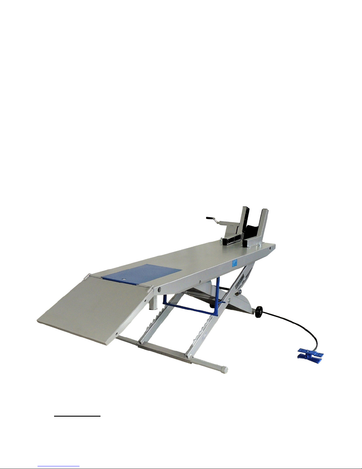
Pneumatic
Motorcycle Lift Bench
M-1000C
Capacity 1,000lbs
Installation, Operation & Maintenance
Manual
WARNING: READ INSTRUCTIONS BEFORE OPERATING
(SHOWN WITH OPTIONAL MOTORCYCLE VISE)
Jun 2018

READ ENTIRE MANUAL TO COMPLY WITH ALL SAFETY AND SERVICE
Lift Platform
PRECAUTIONS. DEATH, PERSONAL INJURY AND/OR PROPERTY DAMAGE MAY
OCCUR UNLESS INSTRUCTIONS ARE FOLLOWED CAREFULLY.
UNPACKING AND SET-UP
• Open crate, then remove ramp and shipping boards.
• Carefully remove lift from crate. (Note: Lift is specifically shipped upside-down.)
• Carefully, flip lift over to normal upright orientation.
• Install tie-down eyelets to front corners of platform.
• Locate & connect foot-operated air valve to 100 psi air supply.
The lift may be damaged and/or personal injury may result if the pressure
exceeds the maximum 100 psi rating.
• Stand clear of lift platform, and depress the UP side of foot valve to raise platform.
• To lower platform, lift safety latch bar from safety latches and lower to next position
or to floor. (Note: The latch bar can also be held in position to fully lower lift by
clipping to underside of platform.)
• Install approach ramp by inserting into holes at rear end of platform.
• Install stabilization bar by removing the cap at one end, then insert bar through
square hole in base of scissor mechanism. Secure with nut & bolt hardware and
reinstall cap.
Drop Out Panel
(Rear Wheel Access)
2
Jun. 2018
M-1000C
OPERATION & SAFETY INSTRUCTIONS
Loads must be centered on platform at all times. Loads also must be firmly
positioned and secured to platform at all times.
1. Only trained persons should operate lift.
2. Center load on platform, not to exceed the 1,000 lbs. maximum weight capacity.
3. Connect to 100 psi maximum shop air to quick disconnect fitting on Foot Valve.
The lift may be damaged and/or personal injury may result if the pressure
exceeds the maximum 100 psi rating.
4. To RAISE depress the ‘UP’ end of Foot Valve. To LOWER depress the ‘DOWN’ end
of Foot Valve. To STOP air flow, position Foot Valve to be level. Once the desired
working height is obtained, always lower lift to rest in the locked & secured position.
5. Keep safety latch bar in locked position at all times, except when raising & lowering.
6. Keep hands and tools from under platform and scissor floor path.
7. Lift must be in the fully lowered position when moving to different locations.
8. The working area should be sufficient to lift motorcycles & power sport vehicles.
9. Foot Valve controller should be positioned at least 3 feet away from Motorcycle Lift
during raising and lowering operation.
10. Lift is recommended for indoor use only.
MAINTENANCE
1. All moving parts have been lubricated at the factory and should be re-lubricated
every (6) months to prevent premature pivot shaft defects. (Note: Grease zerks are
located at each and of frame pivot shaft and at top ends of inside frame assembly.)
2. Lightly oil cylinder rod when it becomes dry.
3. Squirt small amounts of oil through air bleed hole in plate end of cylinder to lubricate
piston and its seal every (6) months.
4. Pivot shaft set screws should be checked frequently to be sure they are tight. (These
are located at the top end of the inside frame assembly.)
OPTIONAL ACCESSORIES
• SIDE EXTENSION SET – Expands width of lift from 24” to 48” includes stabilizer bar.
• FRONT EXTENSION – Extends lift top to 93” for longer wheel base motorcycles.
• CYCLE VISE – Used to assist in stabilizing motorcycle while on lift, when using tie-downs.
3
Jun. 2018
M-1000C

EXPLODED VIEW & PARTS LIST
39
4
Jun. 2018
M-1000C

OPTIONAL ACCESSORIES INSTALLATION
PARTS LIST
SIDE EXTENSION SET
• Insert pipes from extension panel package through holes in lift platform. Long pipe
mounts to the front and the short pipe mount to the rear.
• Insert M8 wing bolt provided through holes on the underside platform to secure end of
pipe to platform.
• Mount side extension panels on ends of pipe for each side of platform, with ramp mount
holes to the rear of lift.
• Secure side extension panels to pipe extensions using the provided ring clips.
• Secure side extension ramps to the center ramp with nuts & bolts provided. Ensure
ramp holes are positioned towards the center ramp.
• Install stabilization bar by removing the cap at one end, then insert bar through square
hole in base of scissor mechanism. Secure with nut & bolt hardware and reinstall cap.
SIDE EXTENSION SET
(INSTALLATION DIAGRAM & PARTS LIST)
(NOTE: INSTALLATION INFORMATION LOCATED INSIDE VICE PACKAGING)
CYCLE VISE
5
Jun. 2018
M-1000C

SIDE EXTENSION SET
(FINAL INSTALLATION DIAGRAM)
Side Extension Ramp
Ramp Mount Pins
Drop Out Panel
Side Extension Panel
Platform
Center Ramp
Ring Clip
13” FRONT EXTENSION
(INSTALLATION DIAGRAM)
6
Jun. 2018
M-1000C

LIMITED WARRANTY
Structural Warranty:
The following parts and structural components carry a five year warranty:
Columns Arms Uprights Swivel Pins
Legs Carriages Overhead Beam
Tracks Cross Rails Top Rail Beam
Limited One-Year Warranty:
Tuxedo Distributors, LLC (Tuxedo) offers a limited one-year warranty to the original purchaser of Lifts and Wheel Service
equipment in the United States and Canada. Tuxedo will replace, without charge, any part found defective in materials or
workmanship under normal use, for a period of one year after purchase. The purchaser is responsible for all shipping
charges. This warranty does not apply to equipment that has been improperly installed or altered or that has not been
operated or maintained according to specifications.
Other Limitations:
This warranty does not cover:
1. Parts needed for normal maintenance
2. Wear parts, including but not limited to cables, slider blocks, chains, rubber pads and pulleys
3. Replacement of lift and tire changer cylinders after the first 30 days. A seal kit and installation instructions will be
sent for repairs thereafter.
4. On-site labor
Upon receipt, the customer must visually inspect the equipment for any potential freight damage before signing clear on
the shipping receipt. Freight damage is not considered a warranty issue and therefore must be noted for any potential
recovery with the shipping company.
The customer is required to notify Tuxedo of any missing parts within 72 hours. Timely notification must be received to be
covered under warranty.
Tuxedo will replace any defective part under warranty at no charge as soon as such parts become available from the
manufacturer. No guarantee is given as to the immediate availability of replacement parts.
Tuxedo reserves the right to make improvements and/or design changes to its lifts without any obligation to previously
sold, assembled or fabricated equipment.
There is no other express warranty on the Tuxedo lifts and this warranty is exclusive of and in lieu of all other warranties,
expressed or implied, including all warranties of merchantability and fitness for a particular purpose.
To the fullest extent allowed by law, Tuxedo shall not be liable for loss of use, cost of cover, lost profits, inconvenience,
lost time, commercial loss or other incidental or consequential damages.
This Limited Warranty is granted to the original purchaser only and is not transferable or assignable.
Some states do not allow exclusion or limitation of consequential damages or how long an implied warranty lasts,
so the above limitations and exclusions may not apply. This warranty gives you specific legal rights and you may
have other rights, which may vary from state to state.
1905 N Main St Suite C, Cleburne, TX 76033
Ph. 817-558-9337 / Fax 817-558-9740
7
Jun. 2018
M-1000C
 Loading...