

Tuxedo FP8K-DS, FP8K-DS-XLT Owners Manual/install Manual
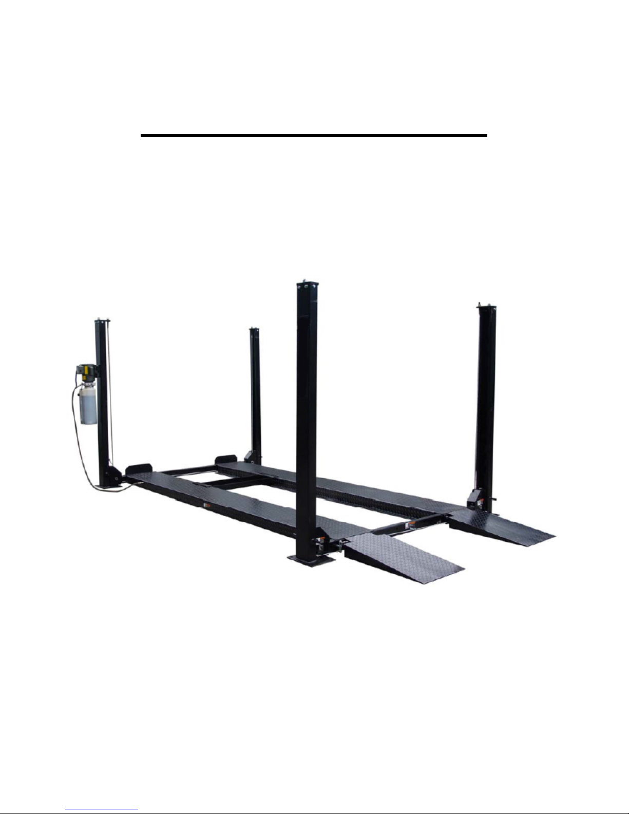
FP8K-DS & FP8K-DS-XLT
Four Post Parking Lifts
8,000 lbs. Capacity
(4,000 lbs. per axle)
INSTALLATION / OWNERS MANUAL
July 2015-B

READ THIS MANUAL THOROUGHLY BEFORE INSTALLING, OPERATING, OR MAINTAINING THIS LIFT.
WHEN DONE WITH INSTALLATION BE SURE TO RETURN DOCUMENTS TO PACKAGE AND GIVE ALL
MATERIALS TO LIFT OWNER/OPERATOR. WHEN INSTALLATION IS COMPLETE BE SURE TO RUN
LIFT UP AND DOWN A FEW CYCLES WITH AND WITHOUT “TYPICAL” VEHICLE LOADED ON LIFT.
TABLE OF CONTENTS
• IMPORTANT INFORMATION
• OWNER / EMPLOYER RESPONSIBILITY
• LIFT SPECIFICATIONS & LAYOUT
• TOOLS REQUIRED
• SELECTING SITE
• MAIN COMPONENTS & ACCESSORY IDENTIFICATION
• INSTALLATION INSTRUCTIONS
• CASTER KIT ASSEMBLY / INSTALLATION
• FOUNDATION & ANCHORING REQUIREMENTS
• SAFETY INSTRUCTIONS & PROCEDURES
• OPERATION INSTRUCTIONS
• PREVENTIVE MAINTENANCE SCHEDULE
• TROUBLESHOOTING
• POWER UNIT PRIMING PROCEDURE
• LATCH & CABLE INSPECTION / ADJUSTMENTS
• EXPLODED VIEWS
• PARTS LIST
• WARRANTY POLICY
IMPORTANT INFORMATION
1. Always inspect the lift for damage and make note of any damage on the bill of lading.
2. In case of freight damage, call the truck line immediately and report the damage as a freight claim.
3. IMPORTANT! Make sure you have extra help or heavy duty lifting equipment when unloading and
assembling the lift.
4. Please read the safety procedures and operating instructions in this manual before operating lift. Keep
this manual near lift at all times. Make sure all operators read this manual.
5. IMPORTANT! Are you installing in a level location? (Lift must be anchored in place if slope is greater
than 1/8” per foot.)
6. Make sure you have enough room to install the lock rods. You will need at least 6’ of clearance from the
opposite end of the power unit end of the lift and 6’ at the power unit end. The power unit may be
installed on the driver front or the passenger rear corner.
7. Never raise a car until you have double checked all bolts, nuts and hose fittings.
8. Always lower the lift to locks before going under the vehicle or storing another vehicle underneath lift.
9. Never allow anyone to go under the lift when raising or lowering.
OWNER / EMPLOYER RESPONSIBILITY
This is a vehicle lift installation/operation manual and no attempt is made or implied herein to instruct the user
in lifting methods particular to an individual application. Rather, the contents of this manual are intended as a
basis for operation and maintenance of the unit as it stands alone or as it is intended and anticipated to be
used in conjunction with other equipment.
Proper application of the equipment described herein is limited to the parameters detailed in the specifications
and the uses set forth in the descriptive passages. Any other proposed application of this equipment should be
documented and submitted in writing to the factory for examination. The user assumes full responsibility for
any equipment damage, personal injury, or alteration of the equipment described in this manual or any
subsequent damages.
2
FP8K-DS / FP8K-DS-XLT
July 2015-B
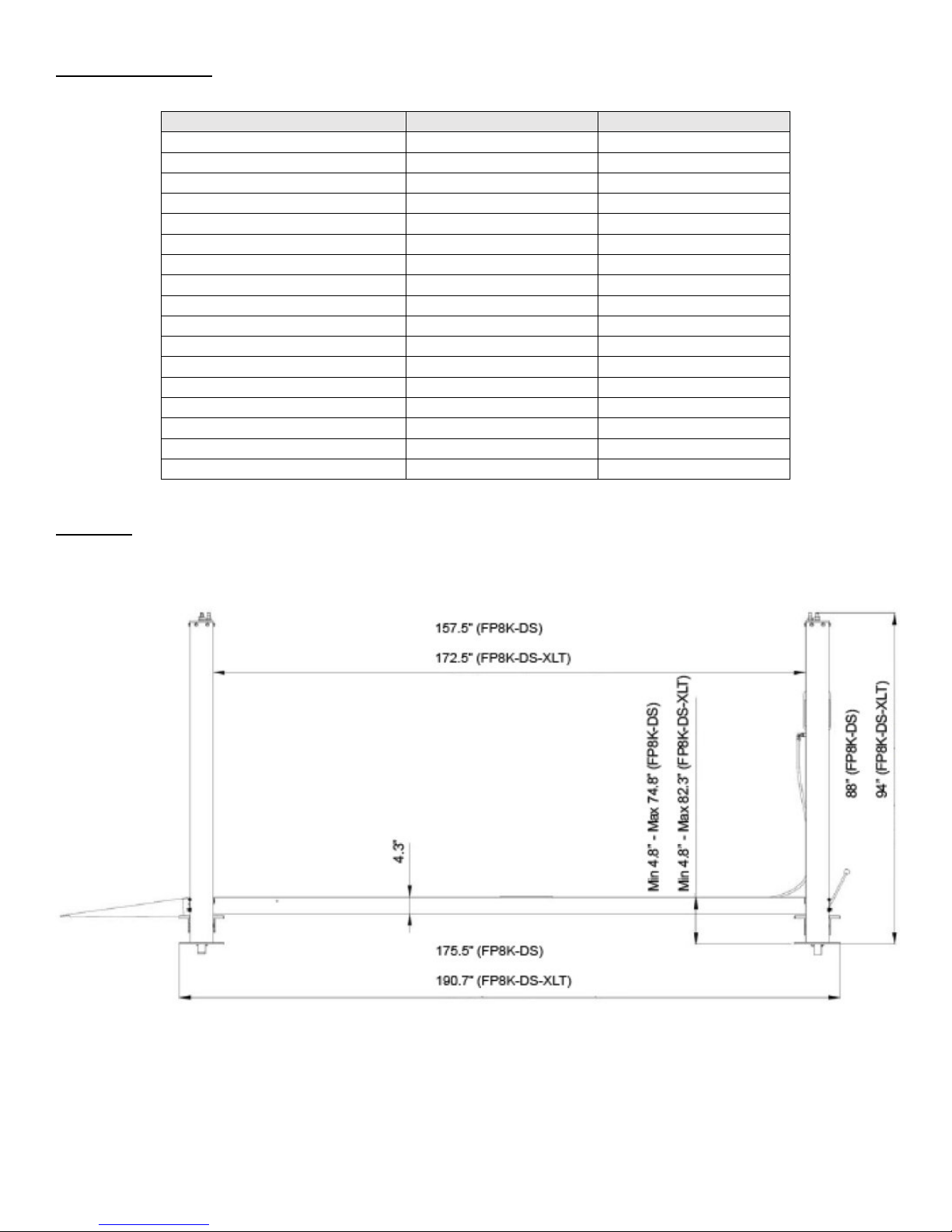
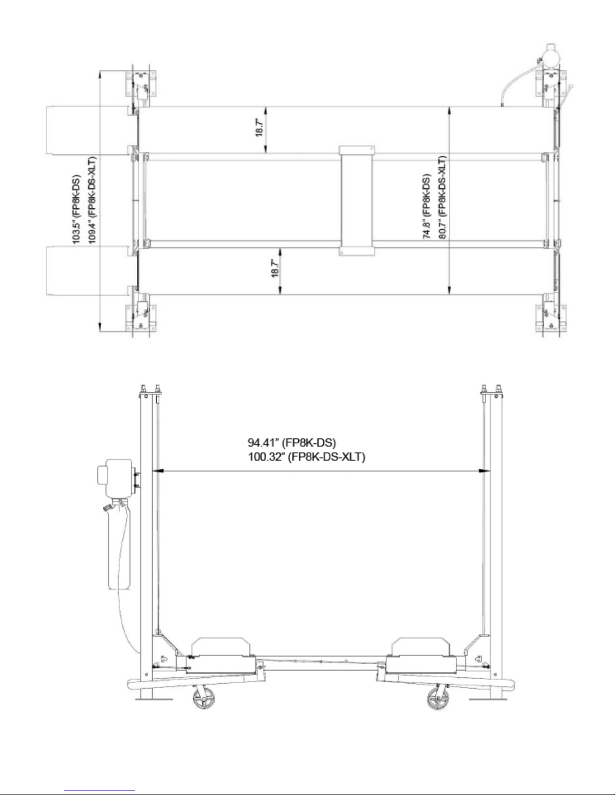
SPECIFICATIONS
Specifications
FP8K
-DS
FP8K
-DS-
XLT
LAYOUT
Lifting Capacity
8000lbs
8000lbs
Overall Length w/ Ramps 207-1/8” 222-1/2”
Overall Length/ No Ramps 175-1/2” 190-5/8”
Overall Width
103-1/2”
109-1/2”
Overall Height 86-1/4” 96”
Track Length 165-1/2” 180-1/2”
Track Width
18-5/8”
18-5/8”
Max Track / Position Width 74-3/4” 80-5/8”
Base Plate Size 10” x 12” 10” x 12”
Lifting Height 74-3/4” 82-1/4”
Width between Posts 94-1/2” 100-5/16”
Length between Post 157-1/2” 172-1/2”
Max Clearance / Under Track 70” 78”
Locking Positions 10 12
Lifting Speed 90S 100S
Power 110V-15 Amp / 1PH 110V-15 Amp / 1PH
Ship Weight 1,690 lbs. 1,785 lbs.
3
FP8K-DS / FP8K-DS-XLT
July 2015-B
4
FP8K-DS / FP8K-DS-XLT
July 2015-B
TOOLS REQUIRED
Set of Metric Wrenches and/or Sockets
Adjustable Wrench
Locking Pliers
25’ Tape Measure
Step Ladder
Hammer
Crow Bar
Chalk Line
Flat Screwdriver
Hex-Key / Allen Wrench Set
Needle Nose Pliers
Rotary Hammer Drill (If anchoring)
3/4" Masonry Bit (If anchoring)
3 Gallons of Hydraulic Oil*
4 Foot Level
*Recommended Oil: ISO 32 Light Hydraulic Oil
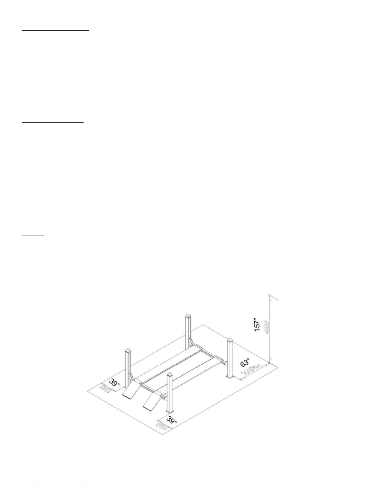
SELECTING SITE
Before installing your new lift, check the following.
OVERHEAD OBSTRUCTIONS: The area where the lift will be located should be free of overhead
obstructions such as heaters, building supports, electrical lines etc.
FLOOR REQUIREMENTS: Visually inspect the site where the lift is to be installed and check for cracked or
defective concrete. This lift must be installed on a solid level concrete floor with no more than 2 degrees of
slope. A level floor is suggested for proper installation and level lifting. If a floor is of questionable slope,
consider a survey of the site and/or the possibility of pouring a new level concrete slab. This lift is designed to
be installed on a minimum of 4" thick, 3500psi, with steel reinforced concrete. Do not install this lift on asphalt,
wood, or any other surface other than described. This lift is only as strong as the foundation on which it is
installed.
NOTE: This Lift does not require bolting to the floor (BUT) If you choose the option to anchor the Lift to
the floor, please follow the detailed instructions in the manual and criteria above. (See page 13)
DO NOT install this lift outdoors unless special consideration has been made to protect the power unit from
weather conditions. The Power unit is not water proof!!!
DO NOT install lift close to wall. It is necessary to leave adequate clearance for safely walking. Suggest
clearance be 1 meter (3 feet) at min.
5
FP8K-DS / FP8K-DS-XLT
July 2015-B

Offside Runway
Ramps
Mainside Runway
Column
C
olumn
C
rossbeam
Power Unit
Wheel
Stop
MAIN COMPONENTS & ACCESSORY IDENTIFICATION
FP8K-DS & FP8K-DS-XLT
Power Unit
Jack Tray
(Bottle Jacks not included)
OPTIONAL ACCESSORIES NOT SHOWN:
• FP8K-DS Drip Trays & FP8K-DS-XLT Drip Trays
• SJ-35 Sliding Scissor Jack – 3,500 lbs. capacity
• Poly Casters
• Aluminum Drive-On Ramps
Steel Caster Kit
6
FP8K-DS / FP8K-DS-XLT
July 2015-B
Drive-On
INSTALLATION INSTRUCTIONS
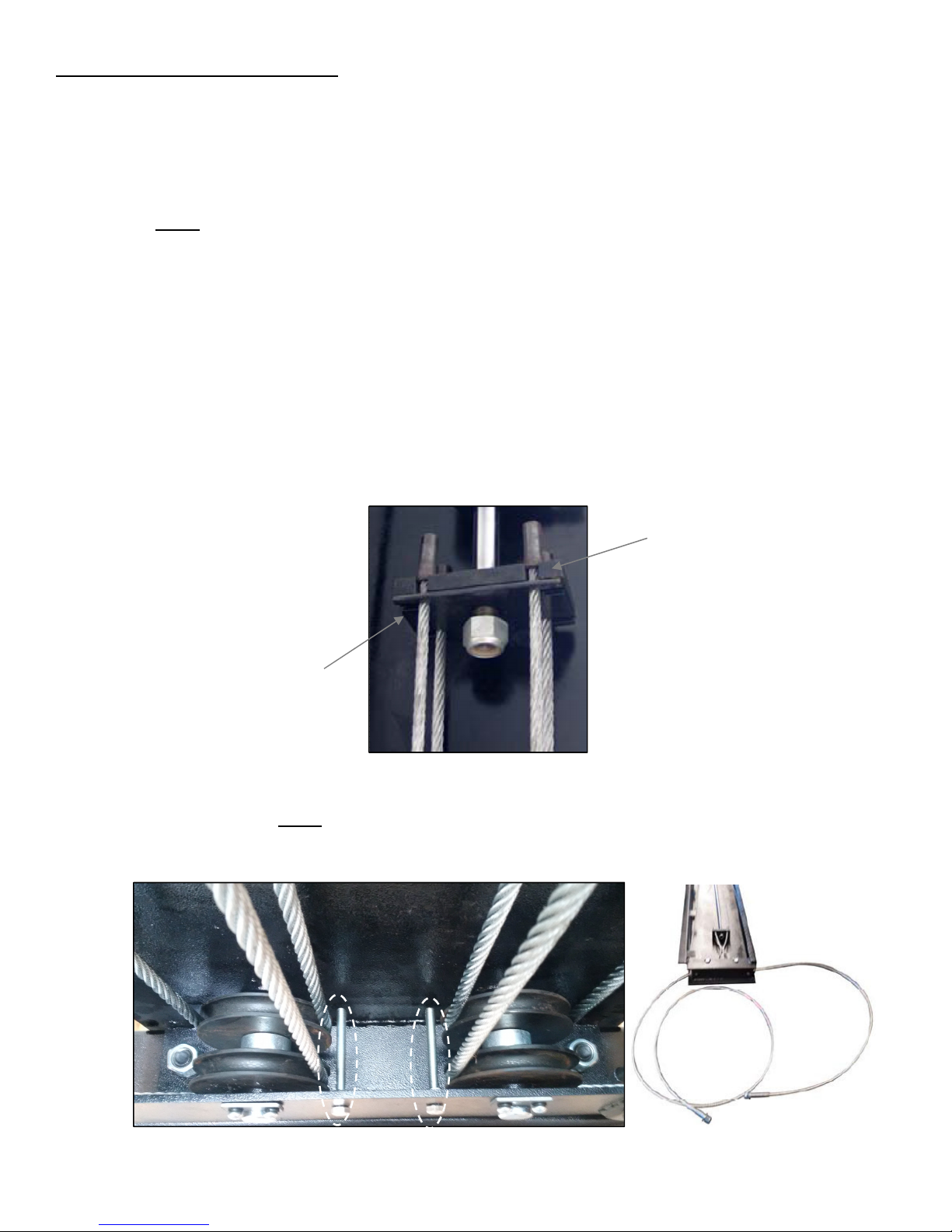
Cable Guide Bolts
Mount Plate
Lock Plate
Improper installation can cause accelerated wear, resulting in catastrophic failure which may cause property
damage and / or bodily injury. Manufacturer will assume no liability for loss or damage of any kind, expressed
or implied, resulting from improper installation or use of this product. Read this installation manual in its entirety
before attempting to install or operate the lift.
1. Remove plastic wrap from top runway and remove all hardware. This includes the Power Unit and Jack
Tray. Note: You should find this manual either attached to the Lift or inside the Power Unit box.
2. While the Mainside Runway (Item # 51) Figures 1 & 3 is upside down, find the end of the Hydraulic
Hose that is already connected to the cylinder. Locate the hole in the side of the runway and install the
90 degree fitting (Item # 86) securing it to runway with Jam Nut.
3. Fully extend the cylinder rod, by pulling the end of the cylinder rod to extend (Item # 56) Figures 3 & 4.
4. Remove lifting Cables (Items # 94, 95, 96 & 97) Figure 4 and layout on floor. Identify the Cable lengths
for proper installation position, based on Figure 4 (page 23) & Parts List (page 27).
5. Using the ‘button head’ cable ends, attach Cables to the Mount Plate located on the end of the
Cylinder. Ensure to anchor the Cables to the Mount Plate using the Lock Plate to lock Cables into
position. IMPORTANT! Double check to ensure Cables are properly installed for routing.
6. Locate the four cable ends and route the appropriate Cable through each hole in corners of the
Mainside Runway, shown in Figure # 4. Take up as much cable slack as possible and lay each cable
back into the runway. Note: Make sure that cables are properly routed around pulleys and are not
in a bind. Refer to Figure 4 for Cable routing detail. Also, ensure Cable Guide Bolts are installed, as
shown below. These assist in keeping the Cables properly engaged to the pulleys.
(Install Cable Guide Bolts, after routing Cables around Pulleys. This maintains the Cables stay on Pulleys)
7
FP8K-DS / FP8K-DS-XLT
July 2015-B
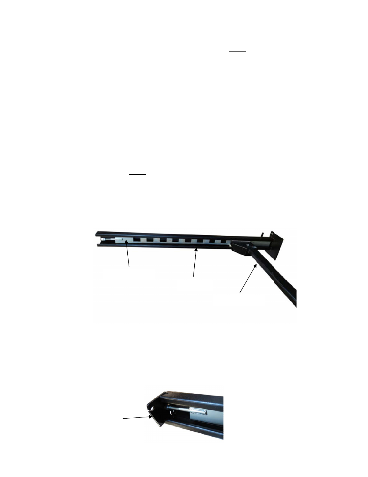
7. Unbolt the top runway (Mainside) from the shipping brackets at each end of the runway, taking the
Lock Ladder
Top Cap
Column
Crossbeam
necessary safety precautions (using some type of a hoist is recommended), as this runway will need to
be flipped over so it is no longer upside down. Place this runway in your bay with the hydraulic fitting
facing toward your previously chosen corner for the power unit. Note: be careful not to pinch or
damage cables.
8. Next unbolt all four columns from the shipping package and place the column with the power unit
mounting bracket in the chosen corner noted in previous steps. Arrange the other three columns in the
remaining corners.
9. Unpack the Crossbeams, Ramps, Safety Latch Linkage Rods and Lock Ladders from bottom Runway.
Remove the Safety Latch covers (Item # 14) Figure # 1 from Crossbeams. They will be reinstalled later.
Arrange the Crossbeams so that the Safety Latches / threaded Bolt for the Locking Linkage is facing
outward to ensure that both of the Connecting Rods (Item # 70) Figure #2 are closest to the power unit
side columns.
10. If you have means for securely lifting the Crossbeam (Item # 67) Figure # 2, lower it into the tops of the
columns. If you don’t, then the columns will have to be placed horizontal on the floor, and the
Crossbeam installed in the columns. Then the entire end structure (two columns and a cross rail) will
need to be stood up as one. Note: Make sure to install Crossbeams so that the Safety Latches /
threaded Bolt are facing to outside of the lift, once stood up. The Cables will run on the inside of
the Crossbeams.
11. Unpack the Lock Ladders (Item # 5) Figure # 1 from the package and slide them into the precut slot on
the Rub Blocks (Item # 56) inside each column. After removing the top nut from the lock ladder you are
ready to install the Top Caps (Items # 3 & 4) Figure # 1 into the columns.
12. Be aware of the offset hole in Top Caps. Arrange them so that the cable mounting holes are closest to
the runways. Use provided bolts, nuts, washers, and lock washers to install Top Caps as shown in
Figure # 1.
13. Secure Top Cap and Lock Ladder assemblies together with Washer and Nut (Items # 7 & 8). Position
the Crossbeams at the second lowest locking position on all columns.
8
FP8K-DS / FP8K-DS-XLT
July 2015-B
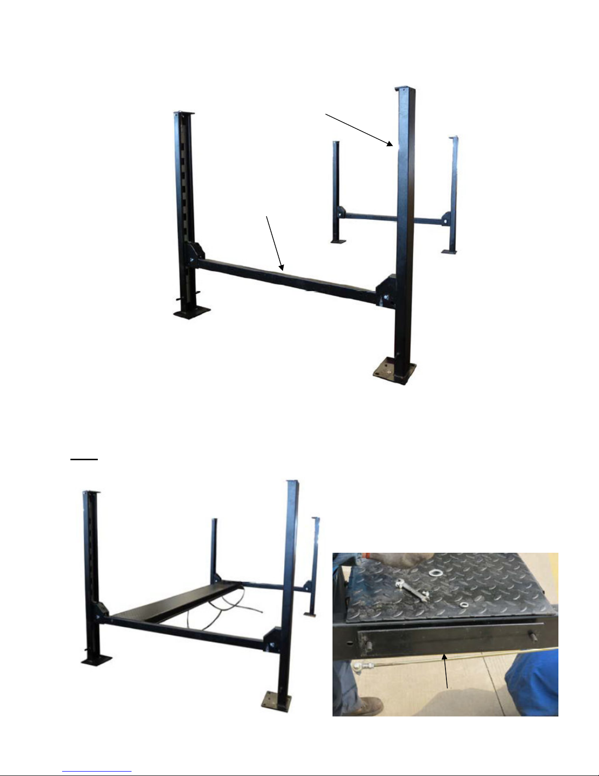
14. Stand-up and arrange the two end structures (Columns & Crossbeams) so that the outside of the cross
Crossbeam
Column
Mounting Plate
rail to the outside of the cross rail measurements are close. Compare the measurements from the left
and the right until they are diagonally within 1/2”. The 1/2” variance will help in mounting the runways.
15. Carefully lift and position each Runway into place and secure with the provided Hex Bolts (Item # 44),
Mounting Plate (Item # 42) and hardware (Items # 45, 46 & 47) as shown in Figure # 1. The lift will
square itself as you further assemble it. Install the Offside Runway (Item # 52) opposite from the
Mainside Runway (Item # 51) and Power Unit Column as shown in Figure # 1.
Note: The Mainside Runway must be installed on the same side as the Power Unit Column.
9
FP8K-DS / FP8K-DS-XLT
July 2015-B
 Loading...