

Page 1
NORMAL OPERATION
By pressing the ON/OFF (1) button, the devices
enters normal operation mode. The display
shows the current temperature of the hot air and
the indicators show the operation mode of the
blower.
OPERATION MODE SELECTION
By pressing the MENU (2) button we can select
the operation mode between MANUAL,
SEMIAUTOMATIC and AUTOMATIC. The
operation mode is shown from the respective
indicators (6), (7), (8).
MANUAL OPERATION (ΜΑΝ)
In this mode of operation the only setting that can
be adjusted is the blower speed. With the keys
``+`` (4) and ``-`` (3) we can select the desired
speed which is steady and independent of the
temperature.
SEMIAUTOMATIC OPERATION (SEMI)
It is basically the same operation as the manual
operation mode with the only difference that the
blower operates only when the temperature of
the hot air is higher that the activation
temperature .
AUTOMATIC OPERATION (AUTO)
In this mode of operation, the speed of the blower
is automatically adjust depending on the
temperature of the hot air. The speed is minimum
when the hot air temperature exceeds the
940841000_09_007
Page 1 from 5
PROGRAMMABLE THERMOSTAT FOR FIREPLACES
BS-841
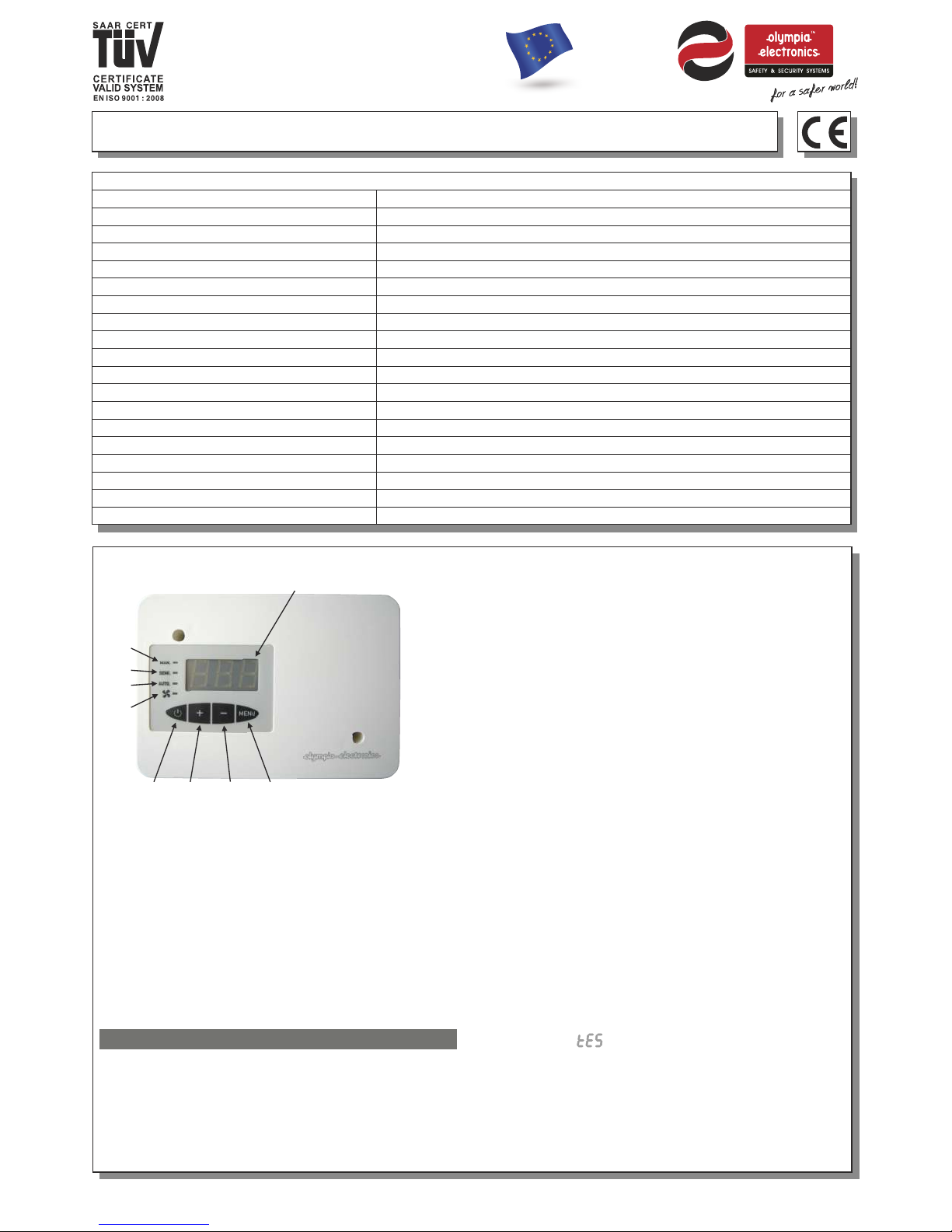
DESCRIPTIONS OF CONTROL BUTTONSINDICATORS
(1). ON-OFF button
(2). Settings selection button
(3). Decrease button
(4). Increase button
(5). LED screen
(6). Manual operation indicator
(7). Semiautomatic operation indicator
(8). Automatic operation indicator
(9). Blower operation indicator
OPERATION
STANDBY MODE
When the product is connected for the first time to
the mains power supply it goes into standby mode. In
the opposite condition press the ON/OFF button. The
display shows 3 dashes and all the indicators are
OFF. In this mode, the device is practicaly not
operational.
(6)
(8)
(7)
(9)
(1) (3) (2)(4)
(5)
TECHNICAL CHARACTERISTICS
OP ER ATI ON TEMPERATURE RANGE
RELATIVE HUMIDITY
SENSOR CONSTRUCTION MATERIAL
EX TE RN AL DIMENSIONS
TY PI CA L WEIGHT (Main unit / + sensor)
GU AR AN TE E
OPERATION VOLTAGE
CO NS UM PT IO N( wi th ou t th e bl ow er )
BLOWER OUTPUT RATING
SENSOR MEASUREMENT RANGE
SENSOR RATING
BLOWER OUTPUT PROTECTION
BL OW ER P OW ER ADJUSTMENT
DE GR EE S OF C OV ER P RO TE CT IO N
PRODUCED IN ACCORDANCE WITH
INDICATORS
SETTING TYPES
SENSOR LENGTH
CONTROL BUTTONS
22 0- 24 0V AC/45-55Hz
20 % - 90 %
o o
-4 0 C to 2 50 C
In te rn al r ep la ce ab le f us e
o o
Up t o 25 0 C fo r th e se ns or h ea d, u p to 2 00 C f or t he c ab le
2 Types. User and Installer
25 0 cm
St ai nl es s st ee l he ad , si li co n ca bl e
20 0W m ax ,85A (0 )
MA NU AL , SE MI AU TO MATIC, AUTOMATIC, BLOWER
ME NU , +, - , ON /O FF
3VA / 2, 5W m ax .
EN 6 10 00 -6 -1 , EN 6 10 00 -6 -3 , EN 6 07 30 -1 , EN 6 07 30 -2 -9
IP 2 0
-1 0 to 6 0 C
o
0 - 90 % RH
2 ye ar s
24 0g r / 31 0g r
137 x 95 x 40 mm
High Quality European based Manufacturers
Page 2
940841000_09_007
2. ADJUSTING THE BLOWER SPEED
INFLUENCING TEMPERATURE
in programing mode (*)
With the second press of the MENU button the
display shows the message for 2 seconds
and after that the blinking current value. This
value only influences the automoatic operation
mode and can be adjusted between 20 C and
80 C by using the buttons ``+`` και ``-``. This
temperature regards the influence of the
temperature to the speed of the blower. If you
have selected the blower activation temperature
of 45 C and 50 C, then the blower will be
activated with a minimum speed at 45 C and will
gradually increase to maximum speed at 95 C.
3. ADJUSTING THE BUZZER ACTIVATION
TEMPERATURE in programing mode (*)
With a third press of the MENU button the display
shows the message (Acoustic buzzer Limit)
for 2 seconds and after that the blinking current
value. The value refers to the temperature above
which the buzzer is activated. It can be adjusted
between 80 C and 180 C, a value of 79 disables
the buzzer. If the buzzer is sounding and a
button is pressed then the buzzer stops. After 5
minutes the temperature is checked and if it is
still above the set value the buzzer will re-sound.
If not then the buzzer will not sound.
4. ADJUSTING THE MINIMUM BLOWER
SPEED LIMIT in programing mode (*)
With a fourth press of the MENU button the
display shows the message (Fan Low Limit)
for 2 seconds and after that, the blinking current
value. This value refers to the lower speed limit of
the blower during the manual and semiautomatic
operation. This value can be adjusted between
20% and 50% by using the buttons ``+`` and ``-``.
5. ADJUSTING THE MAXIMUM BLOWER
SPEED LIMIT in programing mode (*)
With a fifth press of the MENU button the display
shows the message (Fan High Limit) for 2
seconds and after that the blinking current value.
This value refers to the upper speed limit of the
blower during the manual and semiautomatic
operation. This value can be adjusted between
50% and 90% by using the buttons ``+`` and ``-``.
6. ADJUSTING THE OVERHEAT LIMIT
in programing mode (*)
With a sixth press of the MENU button the
display shows the message (temperature
High Alarm) for 2 seconds and after that the
blinking current value. The value refers to the
overheating level of the fireplace and can be
adjusted between 100 C and 200 C using the
buttons ``+`` and ``-``. When the temperature of
the hot air exceeds this limit the buzzer sounds
and the blower is activated with a maximum
o
o
o o
o
o
o o
o o
,
Page 2 from 5
activation temperature , and gradually
increase until is reaches it’s maximum value.
The buttons ``+`` and ``-`` do not operate.
If no button is not pressed for 3'' during the
setting mode, the device will automatically show
the initial screen with the temperature of the hot
air while simultaneously storing the settings.
The buttons``+`` and ``-`` , have a repetition
function.
KEYBOARD LOCK
If it is required that the keyboard is locked so as
to prevent unathorized usage (eg. From small
children) it can be locked if the MENU button is
pressed unitl the message is shown(about
5'' ). After this, every press of a button shows this
message and the device does not accept any
commands. This lock function does not affect the
ON/OFF button which operates normaly. The
keyboard can be unlocked by pressing the MENU
button until the message is shown on the
display.
These settings do not refer the the user and must
be done by qualified personel. The device must
be in standby mode (page 1). To enter this
seeting mode press the ON/OFF button for >5
seconds or more while the device is in standby
mode. The display shows (programing mode)
and the device is ready to accept new settings.
FACTORY SETTINGS
Operation mode ............................... : Automatic
Blower speed ΜΑΝ-SEMI ..................... : 50%
Blower activation temp. SEMI-AUTO .... : 45 C
Minimum blower activation temp. .......... : 35 C
Maximum blower activation temp. ........ : 80 C
Blower speed influencing temp. ............ : 50 C
Buzzer activation temp........................... : 120 C
Minimum blower speed........................... : 20%
Maximum blower speed.......................... : 90%
Overheating temperature........................ : 140 C
Blower activation temp. hysteresis .......... : 2 C
To reset to factory default setting see
paragraph 8 (page 3).
1. ADJUSTING THE BLOWER ACTIVATION
TEMPERATURE in programing mode (*)
With the first press of the MENU button, the
display shows the message for 2 seconds
and after that the temperature that the blower is
activated can be adjusted. When the hot air
temperature exceeds this temperature then the
blower is activated. This is used for manual and
semiautomatic operation. The value can be
adjusted between 35 C and 80 C.
INSTALLER SETTINGS (*)
o
o
o
o
o
o
o
o o
Page 3
940841000_09_007
Page 3 from 5
speed. The display shows the message
(burn) until the temperature is decreased to an
acceptable level where the device returns to the
previous operation mode. If a button is pressed,
the buzzer is deactivated for 5 minutes. The
buzzer will be reactivated if after 5 minutes the
temperature is still above the alarm limits. This
procudure will be continued unitl the temperature
levels are normal.
7. ADJUSTING THE HYSTERESIS
TEMPERATURE in programing mode (*)
With a seventh press of the MENU button, the
display shows the message (Hysteresis) for
2 seconds and after that the blinking current
value. This level refers to the temperature where
the blower is deactivated in regards to the
activation temperature. If the activation
temperature is set to 45 C and the hysteresis
temperatures is set to 5 C, then the blower will be
activated at 45 C and will be deactivated when
the hot air temperature drops to 40 C. This value
can be adjusted between 1 C and 30 C by using
the buttons ``+`` και ``-``.
8. RESETTING TO FACTORY DEFAULT
SETTINGS in programing mode (*)
With a ninth press of the MENU button, the
display shows the message (Factory).
If one of the buttons ``+`` or ``-`` is pressed then
all the settings are restored to factory defaults.
Every new press of the MENU button, from this
point on repeates the setting cycle. In order to
complete and store the settings press the
ON/OFF button and the device will enter normal
operation mode.
9. SENSOR ERROR
If for any reason the temperature sensor has a
short circuit the the display shows
(Error Low) the buzzer is sounded and the
blower is deactivated. This state is active for as
long as the problem exists. If the temperature
sensor has an open circuit then the display
shows (Error High). If the device is set to
standby mode with the ON/OFF button, the
buzzer is deactivated.
o
o
o
o
o o
INSTALLATION
To install the device follow the installation
instructions described on page 4.
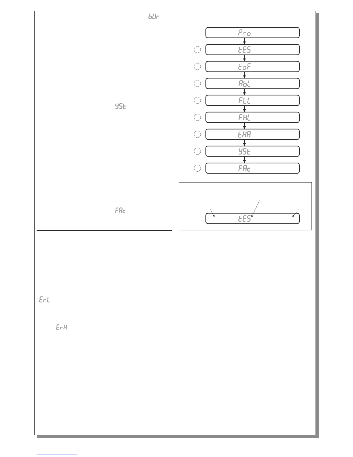
35 to 80ºC
35 to 80ºC
45ºC
45ºC
50 to 90%
90%
100 to 200ºC
140ºC
1 to 30ºC
2ºC
Value name
Factory value
adjustment range
+ or -
20 to 80ºC
50ºC
80 to 180ºC
120ºC
20 to 50%
20%
Value explanation
1
2
3
4
5
6
7
8
Quick programing guide
Page 4
940841000_09_007
Page 4 from 5
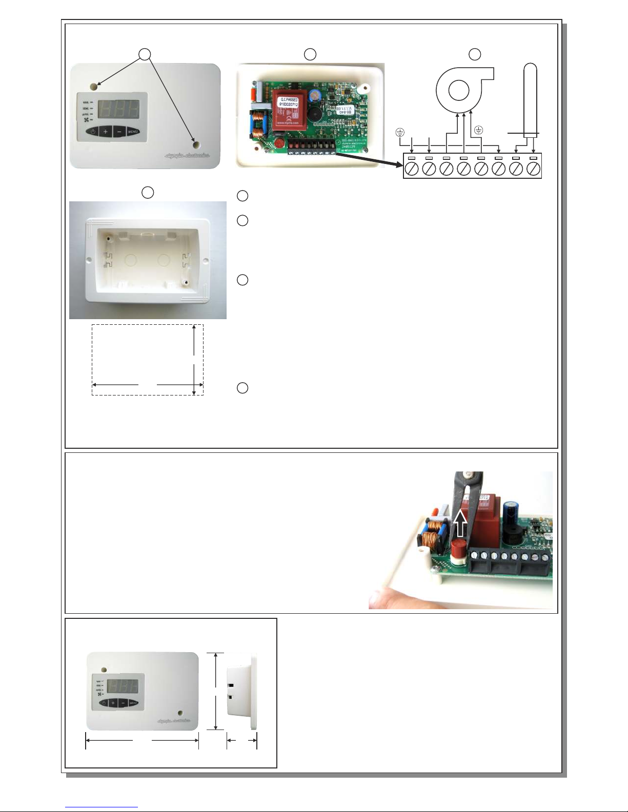
SENSOR
Dimensions in mm
1 To install the device, remove the front plastic cover by
unfastening the retaining screws.
2 Produce the required opening to install the plastic base, after
opening the pre etched cable entries.
ATTENTION!!! Make sure that the operation temperature of the
device in the installation area, must not exceed the operation
limits.
3 Make the electrical connections as shown in the diagram.
Connect the neutral cable to the N terminal, connect the phase
terminal to the L terminal and connect the ground cable to the
POWER EARTH terminal.
WARNING!!! Every metallic part of the fireplace should
be connected to the ground terminal.
The SENSOR is connected to the S1, S2 terminals and it is
installed in the measuring point with the included screw. The
BLOWER cables are connected to the M1, M2 terminals.
4 After all the connections are finished, replace the front plastic
cover and install the fastening screws. Place the included cups
and the device is now ready to be activated.
3
Installation instructions
REPLACING THE FUSE
137
95
40
If the blower is not operating then the most usual cause is a
faulty fuse. To replace the fuse, the top cover must be
removed according to step 1 of the installation instructions.
Use a needle nose plier to remove the faulty fuse (as show in
the photo) and replace it with a new fuse of the same type
and rating. Refit the top cover according to step 4 of the
installation instructions.
1
3
2
115
The required opening to install
the plastic base in mm.
73
N
L
Page 5

940841000_09_007
Page 5 from 5
WARRANTY
Olympia Electronics guarantees the quality, condition and operation of the goods. The period of
warranty is specified in the official catalogue of Olympia Electronics and also in the technical leaflet,
which accompanies each product. This warranty ceases to exist if the buyer does not follow the
technical instructions included in official documents given by Olympia Electronics or if the buyer
modifies the goods provided or has any repairs or re-setting done by a third party, unless Olympia
Electronics has fully agreed to them in writing.
Olympia Electronics reserves the right to repair or to replace the returned goods and to
the buyer depending on the reason of defection. Olympia Electronics reserves the right to charge or
not the buyer the transportation cost.
Products that have been damaged can be returned to
the premises of our company for repair or replacement, as long as the warranty period is valid.
or not charge
HEAD OFFICE
72
P.C. 60061 Greece
nd km. O.N.R. Thessaloniki-Katerini
www.olympia-electronics.gr
[email protected]
Congratulations for your selection to buy this product.
Olympia Electronics - European manufacturers.
 Loading...