

Page 1

Operation and
Maintenance Manual
Electronic Table-Top Autoclaves
Models EZ9Plus & EZ11Plus
Cat. No. MAN205-0443001EN Rev U
Manufactured by:
Tuttnauer Co. Ltd., Har Tuv Industrial zone B P.O.Box 170, Beit Shemesh
99000, IsraelTel: 972 2 9904611, Fax: 972 2 9904730
Tuttnauer U.S.A. Co, Ltd. 25 Power Drive Hauppauge, NY, 11788, USA.
Tel (631) 737 4850, (800) 624 5836, Fax: (631) 737 0720
Page 2

http://www.tuttnauerusa.com/
Page 3

Page 1
TABLE OF CONTENTS
PARAGRAPH PAGE NO.
1. GENERAL...................................................................................................................................5
1.1 INCOMING INSPECTION.......................................................................................................... 5
1.2 WARRANTY................................................................................................ ............................ 5
1.3 WARRANTY STATEMENT ................................................................................................ ....... 6
2. SAFETY INSTRUCTIONS..............................................................................................................7
3. GENERAL INFORMATION ..........................................................................................................8
3.1. INTRODUCTION .......................................................................................................................... 8
3.2. OPERATING CONDITIONS ................................................................ ........................................... 10
3.3. SPECIFICATIONS........................................................................................................................ 10
3.4. ELECTRICAL DATA ................................................................ ..................................................... 14
3.5. ENVIRONMENTAL EMISSION INFORMATION ................................................................................... 14
3.6. CONSTRUCTION................................................................ ........................................................ 14
3.7. SYMBOL DESCRIPTION ............................................................................................................... 15
3.8. WATER QUALITY ...................................................................................................................... 15
3.9. DIRECTIVES AND STANDARDS ................................................................ ...................................... 16
3.9.1. Technical Directives........................................................................................................ 16
3.9.2. Technical Standards ....................................................................................................... 16
4. CONTROL PANEL .....................................................................................................................21
4.1. DESCRIPTION AND FUNCTIONS OF THE FRONT PANEL....................................................................... 22
4.1.1. Visual Information Center.............................................................................................. 22
4.1.2. The Control Center ......................................................................................................... 22
4.1.3. Data Center ....................................................................................................................23
4.2. DISPLAYED ERROR MESSAGES / SYMBOLS ................................................................ ..................... 24
4.3. DISPLAYED OPERATIONAL MESSAGES / SYMBOLS ............................................................................. 25
5. EZVIEW SCREENS ....................................................................................................................26
5.1. SCREENS SHOWING A SUCCESSFULLY COMPLETED CYCLE.................................................................... 26
5.2. SCREENS SHOWING ABORTED CYCLES AFTER A COMPLETED STERILIZATION STAGE ................................. 27
5.2.1. Canceled by user AFTER complete sterilization stage ................................................... 27
5.2.2. Door is open AFTER the sterilization stage has finished ............................................... 28
5.2.3. Screens showing a High Pressure Failure AFTER a completed sterilization stage .......28
5.3. SCREENS SHOWING A FAILED CYCLE: ............................................................................................. 29
5.3.1. Screens showing a failure because of a Heat Time Error ..............................................29
5.3.2. Failure due to Cancellation by user BEFORE completing the sterilization stage.......... 30
6. STERILIZATION PROGRAMS.....................................................................................................31
6.1. PROGRAM 1: UNWRAPPED INSTRUMENTS..................................................................................... 33
6.2. PROGRAM 2: WRAPPED INSTRUMENTS, POUCHES.......................................................................... 34
6.3. PROGRAM 3: UNWRAPPED DELICATE INSTRUMENTS................................ ....................................... 35
6.4. PROGRAM 4: HANDPIECES ................................................................ ......................................... 36
6.5. PROGRAM 5: CHAMBER BRITE CLEANING...................................................................................... 37
6.6. PROGRAM 6: CALIBRATION CYCLE ............................................................................................... 38
6.7. PROGRAM 7: EXTRA DRYING TIME .............................................................................................. 39
6.8. PROGRAM 7: CUSTOM A (MAY BE ALTERED BY THE USER)................................................................ . 40
6.9. PROGRAM 8: CUSTOM B (MAY BE ALTERED BY THE USER)................................ ................................. 41
7. CHECKING AND CHANGING PARAMETERS AND OTHER DATA .................................................42
7.1. QUICK OPTIONS DIRECTORY ................................................................................................ ....... 43
7.1.1. Add extra dry time .........................................................................................................43
7.1.2. Export to USB ................................................................................................................. 44
Page 4

Page 2
7.1.3. Print cycles...................................................................................................................... 46
7.1.4. Version information ....................................................................................................... 47
7.1.5. Start cycle by clock .........................................................................................................47
7.1.6. Set date and time ...........................................................................................................49
7.1.7. Login ............................................................................................................................... 50
7.1.8. Exit..................................................................................................................................52
7.2. MAIN MENU ................................................................ ........................................................... 52
7.2.1. Cycle Parameters for Custom A and B cycles ................................................................ 53
7.2.2. Modifying a parameter for the Custom A and B cycles ................................................ 54
7.2.3. System Parameters ........................................................................................................56
7.2.4. Maintenance .................................................................................................................. 59
7.2.4.1. Export Gain and Offset to USB .................................................................................. 60
7.2.4.2. Reset atmospheric pressure ...................................................................................... 61
7.2.4.3. Printer Test (for units with an optional printer) .......................................................61
7.2.4.4. Print All Gain and Offset (for units with an optional printer) ..................................63
7.3. TABLE OF PARAMETERS ................................................................ ............................................. 64
8. PRINTER.................................................................................................................................. 70
8.1. PRINTER OUTPUT (FOR UNITS WITH OPTIONAL PRINTER)................................................................... 70
8.2. PRINTER HANDLING (FOR UNITS WITH AN OPTIONAL PRINTER)........................................................... 73
8.2.1. Maintenance .................................................................................................................. 73
8.2.2. Installing printer paper .................................................................................................. 73
8.2.3. Notes on treatment of thermal papers: ........................................................................ 75
9. INSTALLATION INSTRUCTION .................................................................................................. 77
9.1. LIFTING AND CARRYING.............................................................................................................. 77
9.2. PLACING ................................................................................................................................. 77
9.3. ELECTRICAL ................................................................ ............................................................. 77
9.4. SETUP .................................................................................................................................... 78
9.5. FILLING THE MINERAL-FREE WATER RESERVOIR. ............................................................................ 78
10. PREPARATION BEFORE STERILIZATION ...................................................................................81
11. OPERATING INSTRUCTIONS..................................................................................................... 86
11.1. TURNING ON THE AUTOCLAVE ..................................................................................................... 86
11.2. PRE-HEATING (EZ11PLUS ONLY) ................................................................................................ 86
11.3. OPENING THE DOOR.................................................................................................................. 87
11.4. ADDING ADDITIONAL DRYING TIME................................................................ ............................... 88
11.5. LOADING ................................................................................................................................ 88
11.6. UNLOADING ................................................................ ............................................................ 92
11.7. STOPPING THE PROCESS MANUALLY.............................................................................................. 92
11.8. STOPPING THE PROCESS DUE TO CYCLE FAILURE............................................................................... 93
12. MAINTENANCE INSTRUCTIONS ...............................................................................................95
12.1. PREVENTIVE AND SCHEDULED MAINTENANCE ................................................................................ 95
12.1.1. Daily........................................................................................................................... 95
12.1.2. Weekly by the operator ............................................................................................ 95
12.1.3. Periodically ................................................................................................................ 99
12.2. DRAINING THE RESERVOIR........................................................................................................ 100
12.3. REPLACING THE DOOR GASKET.................................................................................................. 101
12.4. CHECKING THE SAFETY VALVE ................................................................................................ ... 104
12.5. CLEANING THE WATER OUTLET STRAINER................................ ..................................................... 105
12.6. WATER SENSOR CLEANING....................................................................................................... 106
12.7. REPLACING THE HEPA AIR FILTER ............................................................................................. 107
12.8. EMERGENCY DOOR OPENING..................................................................................................... 108
12.8.1. Relieve pressure from inside the chamber .............................................................109
12.8.2. Opening the door .................................................................................................... 110
Page 5

Page 3
13. TROUBLESHOOTING..............................................................................................................111
14. SPARE PARTS LIST ................................................................................................................. 117
15. ACCESSORIES ........................................................................................................................117
Page 6

Page 4
TABLE OF CONTENT (Cont.)
DRAWINGS PAGE NO.
FRONT VIEW – EZ9PLUS ........................................................................................ 17
REAR VIEW – EZ9PLUS ........................................................................................... 18
FRONT VIEW – EZ11PLUS ......................................................................................19
REAR VIEW – EZ11PLUS......................................................................................... 20
POUCH RACK AR910 ...........................................................................................117
TRAY HANDLE CMT240-0097............................................................................. 117
TRAY TRY254-0003............................................................................................... 118
TRAY HOLDER FOR EZ11PLUS TRH411-0021 ..............................................118
Page 7

Page 5
1. GENERAL
Read the Operating Instructions carefully, before beginning any
operation on the autoclave!
1.1 Incoming Inspection
Upon receiving your Tuttnauer Autoclave, carefully inspect the
outside of the shipping carton for signs of damage. If any damage
to the carton is found, note the location with respect to the
autoclave and check that area of the autoclave carefully once it is
fully unpacked. Observe packing method and retain packing
materials until the unit has been inspected. Mechanical inspection
involves checking for signs of physical damage such as:
scratched panel surfaces, broken knobs, etc.
If any damage is found, contact your dealer as soon as
possible so that they can file a claim with the shipping carrier
and also notify Tuttnauer.
All Tuttnauer products are carefully inspected prior to shipment
and all reasonable precautions are taken in preparing them for
shipment to assure safe arrival at their destination.
Note: Lifting and carrying should always be done by two people.
1.2 Warranty
Tuttnauer warrantees, from the date of purchase, all new EZPlus
autoclaves for a period of two full years, covering both parts and
labor.
This two year warranty covers defects in materials and
workmanship on every part in the autoclave except door gaskets
and HEPA filters (they are considered wear items).
Tuttnauer warrantees the chamber for a period of ten (10) years
against defects in materials and workmanship.
This warranty does not include installation or operator instruction
which are covered in this manual for your convenience or which
can be provided by your dealer.
This warranty does not apply to any instrument that has
been subjected to improper use or accident, nor shall it
extend to autoclaves that have been repaired or altered
outside the factory without prior authorization from
Tuttnauer.
The warranty also does not include routine cleaning or
preventive maintenance, to be performed according to
instructions in Sec. 12.1 (Preventive and Scheduled
Maintenance).
Page 8

Page 6
Tuttnauer’s obligation is limited to the repair or replacement of
parts for the autoclave.
No other warranties or obligations are expressed or implied.
The Autoclave should only be used in a manner described in
this manual!
1.3 Warranty Statement
To activate the warranty, the registration card must be completed
and mailed or faxed to Tuttnauer within fourteen (14) days of
purchase or you may call our customer service department at the
number listed below.
Products will only be received and accepted for repair from an
authorized dealer and only with prior return authorization from
Tuttnauer. All transportation charges to and from Tuttnauer must
be paid by the owner of the autoclave. Tuttnauer will not accept
COD shipments. If repairs are needed during the first 90 days
after purchase of this autoclave and a local authorized service
dealer is not available, Tuttnauer will arrange pick up of the unit at
Tuttnauer’s expense. This will be on an individually evaluated
basis and ONLY with pre-approval.
Note: If you have any questions or there are any difficulties with this
instrument and the solution is not covered in this manual, please
contact your dealer or Tuttnauer USA Co. Do not attempt to service
this instrument yourself.
Tuttnauer USA Co., Ltd., 25 Power Drive Hauppauge, NY 11788,
USA
: (800) 624 5836, (631) 737 4850, Fax: (631) 737 0720
e-mail:info@tuttnauerUSA.com.
Page 9

Page 7
2. SAFETY INSTRUCTIONS
The autoclave has unique characteristics. Please read and understand
the operation instructions before first operation of the autoclave. This
manual includes instructions and guidance provided by the
manufacturer: how to operate the autoclave, the door safety
mechanism, and the dangers involved in circumventing safety means,
how to ensure that the door is closed, and how to select a correct
sterilization program.
Make sure that you know where the main power switch is located.
Autoclave maintenance is crucial for the correct and efficient function of
the device.
Never use the autoclave to sterilize corrosive products, such as: acids,
bases and phenols, volatile compounds or solutions such as ethanol,
methanol, chloroform or radioactive substances. Below are the
operating instructions – safety instructions:
1. All autoclave users must receive training in proper usage from an
experienced employee. Every new employee must undergo a
training period under an experienced employee.
2. When sterilizing plastic materials, refer to the item manufacture
information and make sure that the item can withstand the
sterilization temperature. Plastic that melts in the chamber is liable
to cause a great deal of damage.
3. On closing the device door, make sure it is properly locked before
activating. Verify that the DOOR OPEN symbol is replaced by
“System Ready”.
4. When withdrawing trays, use the enclosed tray handle or wear
heat resistant gloves.
5. The door is electronically locked and will not open unless the
pressure in the chamber equals the atmospheric pressure
(chamber pressure is displayed on the screen).
6. The door also remains locked if there is a cycle failure or the unit
has no power.
7. Open the door slowly to allow steam to escape.
8. Once a month, ensure that the safety valve is operating, and once
every 5 years a certified inspector must perform a chamber
pressure safety test.
9. Make sure there are no leaks, breaks, blockages, whistles or
strange noises.
10. Perform maintenance operations as instructed. The owner of the
autoclave is responsible to perform the maintenance operations.
11. Notify the person in charge immediately of any deviation from the
proper function of the device.
12. Protective equipment and clothes and other safety instructions
should be implemented in accordance with local and national
regulations and/or rules!
Page 10

Page 8
3. GENERAL INFORMATION
3.1. Introduction
The EZPlus tabletop autoclave is designed for sterilization of
wrapped and unwrapped instruments, and related items found in
dental, medical, and veterinary clinics, first aid rooms, hospitals,
laboratories etc.
This autoclave is an electrically – heated sterilizer using steam
as the sterilizing agent. This unit uses steam flush pressure
pulse technology for removing air from the chamber. A
computerized control unit ensures a fully automatic sterilization
cycle, control and monitoring of physical parameters and a clear
documentation of the sterilization cycle.
The autoclave offers a choice of four automatic programs and
two custom programs designed to match the material to be
sterilized. In addition there is a dedicated cleaning program. The
autoclave is equipped with an Air Assisted Drying system. This
includes an air pump that during the drying stage draws air
through a HEPA filter (0.2µm) and circulates that air through the
heated chamber to remove moisture and facilitate the drying
operation. Drying is performed with the door closed.
On all models, a water pump is installed between the water
reservoir and the chamber. This pump guarantees fast and
accurate filling of the chamber every time. Entry of water may be
accompanied by a noise for approximately 30 seconds. This is
normal noise generated by the regular operation of the pump.
The EZPlus series features a digital absolute pressure display
for monitoring and control purposes. The pressure display
indicates if there is pressure in the chamber. The device is
capable of displaying the pressure in psia, psig, or in kPa
according to the operator’s requirements. When the pressure is
displayed in psig, the atmospheric pressure is shown (at sea
level) as 0 psig. If the pressure is defined in psia or kPa the
absolute zero is displayed as “0” and the atmospheric pressure
is shown (at sea level) as 14.7 psia or 100 kPa respectively.
Note: This unit comes from the factory with the pressure
parameter set to display in psig.
The EZPlus can display temperature in ºF or ºC.
Note: The unit comes from the factory set to display
temperature in ºF.
Page 11

Page 9
The control system is designed to meet the most current
sterilization standards to ensure efficacy, safety of personnel
and reliable operation. See sec. 3.9
A printer is an optional addition to the autoclave. The printer
prints the preset and actual parameters of the cycle
(temperature, time and pressure).
The EZPlus features built in memory to record up to 100
sterilization cycles. These can be reprinted on the optional
printer or exported to a USB device to be transferred to a PC.
The EZPlus has a built in Network Port for use with Tuttnauer’s
R.PC.R software when connected to your local network.
The R.PC.R software has been developed especially for the
Tuttnauer autoclaves.
This application will allow you to:
Monitor up to 8 autoclaves
Monitor the real time activity of any autoclave connected via
the network port.
Manage the history files of the cycles run on your autoclave.
The history files can be downloaded either directly through a
physical connection to the network port or transferred
manually using a USB device.
Store all the history of the processes that have been run on
your autoclave
Track the parameter setting that have been used in each of
the cycles and stages run.
Choose the style of the report to view; either graph, table, or a
print out
All reports can be saved as a PDF.
The graph style report offers the user an option to customize
the inputs and outputs used in the presentation.
For more information on the R.PC.R refer to the R.PC.R user
guide.
This manual is intended for the user and gives the user a
general understanding of the instrument and the best ways to
operate and take care of it in order to obtain effective results.
Before operating this autoclave read carefully this operation
manual. After reading this manual, operating the autoclave will
be easy. However since this instrument is built with high
technology sensitive components, no attempt should be made
by the user or any other unauthorized person to repair or
recalibrate it.
Page 12
Page 10
Only technical personnel, of an authorized Tuttnauer dealer,
having proper qualifications and holding technical
documentation (including a technician manual) and
adequate information are authorized to service the
apparatus.
3.2. Operating Conditions
This device is for indoor use only!
The minimum counter depth for the EZ9Plus and EZ11Plus is 22
inches.
Counter tops or slide-outs need to have a minimum capacity of
175 pounds for the EZ9Plus and 190 pounds for the EZ11Plus.
The sterilizer should be loaded only with autoclavable material!
Minimum room ventilation shall be 10 cycles per hour.
The environment shall not exceed an ambient temperature range
of from 41ºF (5ºC) to 104ºF (40ºC) and a relative humidity of
85%.
The operational altitude shall not be over 6562 feet (2000
meters) (ambient pressure shall not be lower than 11.6 psia (80
kPa)).
Operate the autoclave only in the manner specified in the
manual. If the equipment is used in a manner not specified by
the manufacturer, the protection provided by the equipment may
be impaired.
CAUTION!
Waste water should be brought into the public net in
accordance with the local rules or requirements
ONLY NON-HAZARDOUS LIQUIDS SHALL BE DISPOSED IN
PUBLIC SEWAGE!
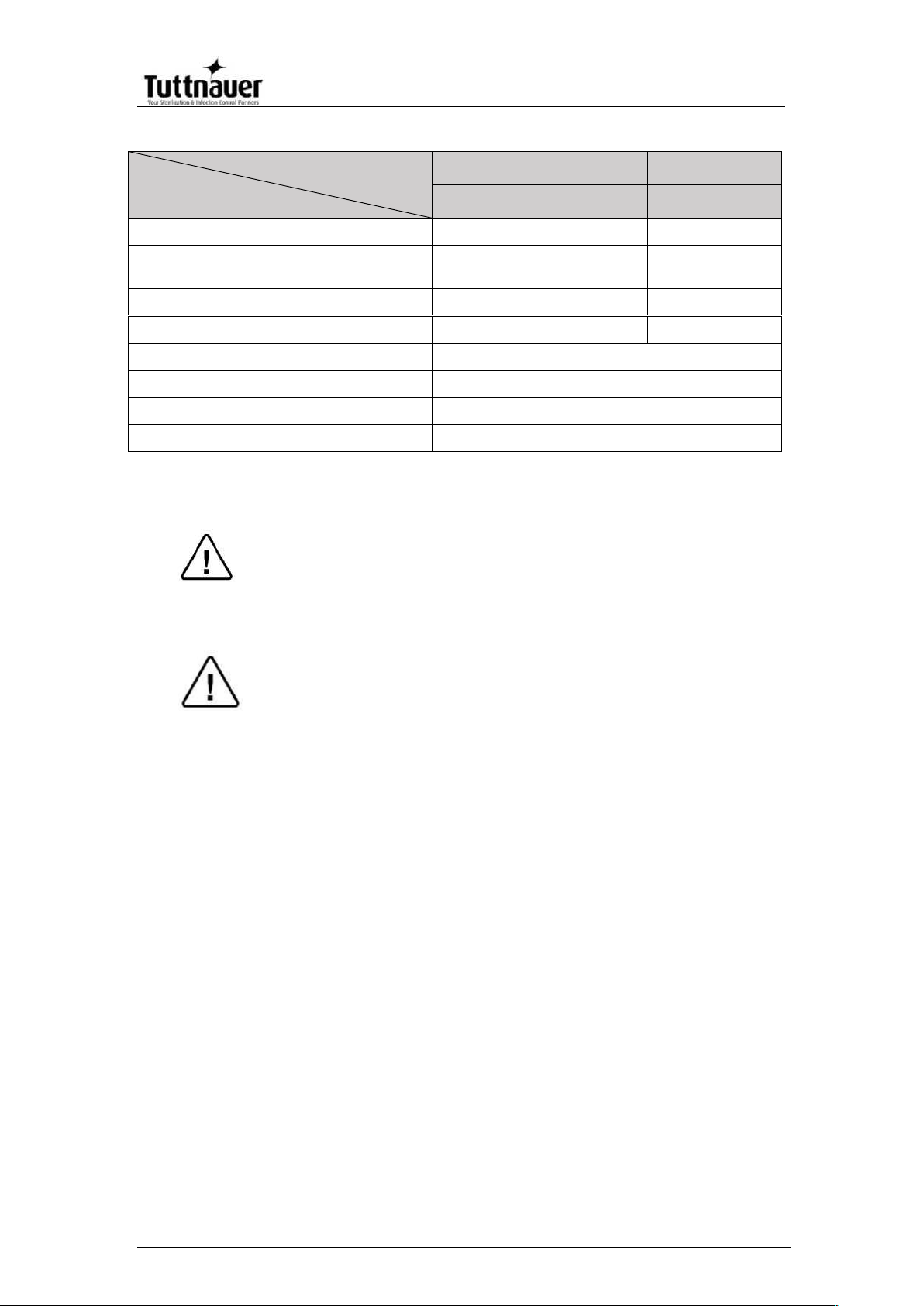
3.3. Specifications
Property
Value
9"
11"
Chamber
Dia.
9” (230 mm)
11” (280 mm)
Depth
19.8” (504
mm)
19.8” (504 mm)
Chamber volume
5.2 gal (19.8 lit)
7.5 gal. (28.5 lit)
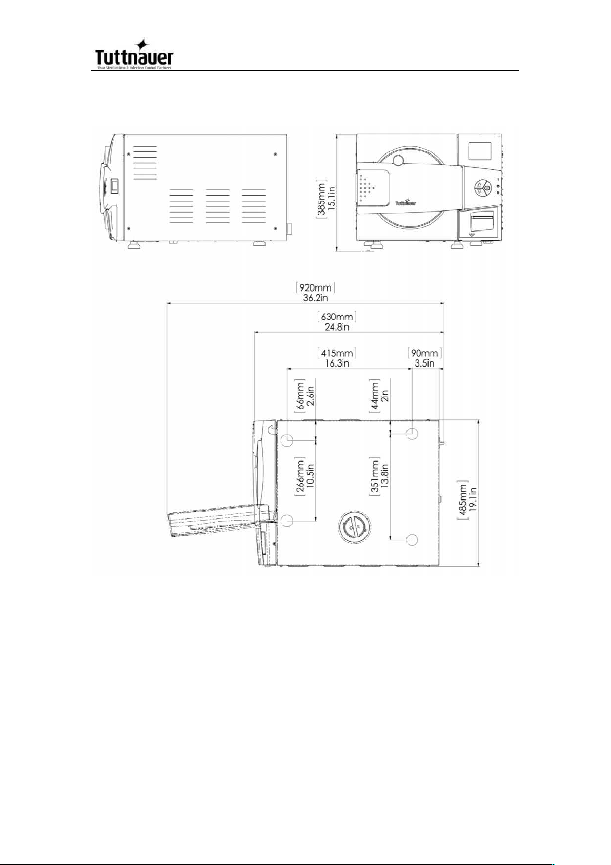
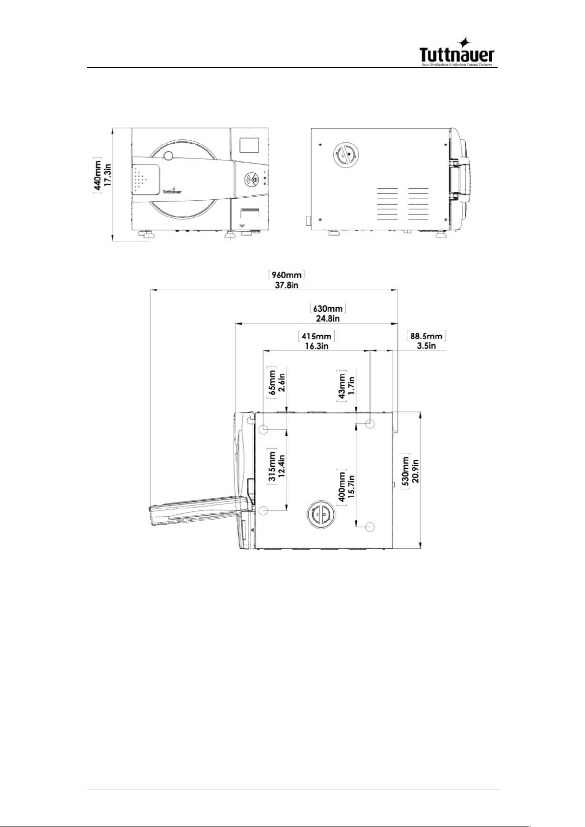
External
dimensions
Width
19.1”(485 mm )
20.9” (530 mm)
Height
15.1” (384 mm)
17.3” (440 mm)
Depth
24.8” (630 mm)
24.8”(630 mm)
Maximum
dimensions (door
open)
36.2”(920 mm)
37.8”(960 mm)
Page 13
Page 11
Property
Value
9"
11"
Distance
between
supporting legs
Between
front and
rear legs
16.3” (415 mm)
16.3” (415 mm)
Front legs
10.5” (266 mm)
12.4” (315 mm)
Rear legs
13.8” (351 mm)
15.7” (400 mm)
Weight
94 lbs. (43 kg)
110 lbs. (50 kg)
Weight w/max solid load and full
reservoir
114.6 lbs. (52 kg)
136 lbs. (62 kg)
Shipping weight
106 lbs. (48 kg)
126lbs. (57 kg)
Weight per support area (max.
load)
Counter tops or slide-outs need to have a
minimum capacity of 175 pounds for the
EZ9Plus and 190 pounds for the EZ11Plus.
Minimum counter depth
22 inches
22 inches
Shipping
dimensions
Width
25” (63.5cm)
25.5” (64.7 cm)
Height
19” (48cm)
22” (55cm)
Depth
29” (75 cm)
29” (75 cm)
Volume
7.97 ft3 (0.23 m3)
9.4 ft3 (0.267 m3)
Mineral-free
water reservoir
Max. water
volume
1.375 US gal (5.2 lit.)
Min. water
volume
0.4 US gal (1.5 lit.)
Maximum solid load per item
1.1 lbs. (0.5 kg)
1.1 lbs. (0.5 kg)
Maximum solid load per tray
3.0 lbs (1.4 kg)
3.0 lbs (1.4 kg)
Maximum solid load
9.0 lbs (4.1 kg)
15 lbs (6.8 kg)
Maximum textile load
1.5lbs (0.7kg)
1.7lbs (0.8)
Tray dimensions
W
6.7” (169 mm)
6.7” (169 mm)
H
0.6” (16 mm)
0.6” (16 mm)
D
16.3” (413 mm)
16.3” (413mm)
Max. Allowable Working
pressure (MAWP)
40 psi (2.8 bar)
No. of trays
3
5
Cassette capacity based on
8”x11” and 8”x 5.5”
Miltex Thompson cassettes
2 full & 2 half
Loaded horizontally
4 full & 4 half
Loaded vertically
Page 14
Page 12
Overall Dimensions – EZ9Plus
Page 15
Page 13
Overall Dimensions – EZ11Plus
Page 16
Page 14
3.4. Electrical Data
Model
Specifications
9"
11"
EZ
EZ
Total Power
1400W
1400W
Voltage
120VAC ±5%, 60Hz / 1
ph*
120VAC ±5%,
60Hz / 1 ph*
Amperage
12A
12A
Recommended circuit breaker
15A
15A
Protection against electrical shock
Class I (IEC 60601-1) (GFCI)
Mains supply fluctuation
+/- 5%
Degree of protection by enclosure
IP31
Electrical Circuit
Dedicated electrical circuit
* According to the local network.
Note:
In order to avoid any injury by electrical hazard, it is mandatory
that a ground fault protection device (GFCI) be installed in the
electrical panel feeding the autoclave (local codes may make
this mandatory).
Attention:
The electrical net must be protected with a current leakage
safety relay (GFCI).
The electrical network must comply with local rules or
regulations.
Verify that there is an easy access to the main power switch
and to the current leakage safety relay (GFCI).
Surge protection is recommended in areas that experience
large voltage or ground fluctuations.
It is recommended that the autoclave be installed on a
dedicated line.
3.5. Environmental Emission Information
1. The peak sound level generated by the autoclave is 65dBa
with background noise of 48 dBa.
2. The total heat per hour transmitted by the autoclave is
<200Wh.
3.6. Construction
The main parts of the autoclave are made of materials as
indicated below:
Chamber is built of stainless steel 316 L.
Door is made of stainless steel 304.
Trays are made of stainless steel 304.
Page 17
Page 15
Water reservoir is made of polyethylene.
Door handle and door cover are made of hard plastic
material, which is safe to touch and thermo-insulated.
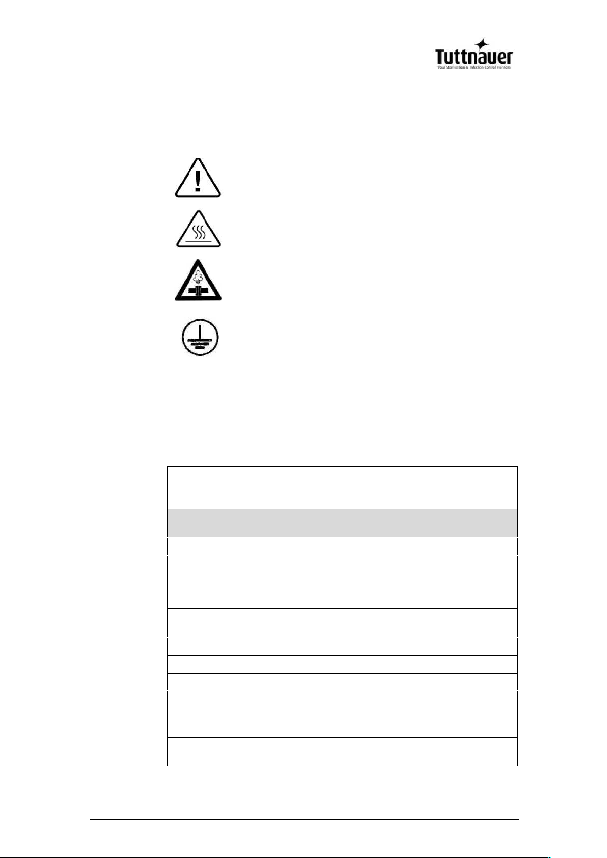
3.7. Symbol Description
3.8. Water Quality
Physical characteristics and contaminants levels
The distilled or mineral – free water supplied to the autoclave
should have the physical characteristics and maximum
acceptable level of contaminants indicated in the table below:
Physical Characteristics and Maximum acceptable
contaminants levels in steam for sterilizers
(According to EN 13060:2004).
Element
Condensate – allowable
content
Silicon dioxide SiO2
≤0.1 mg/kg
Iron
≤0.1 mg/kg
Cadmium
≤0.005 mg/kg
Lead
≤ 0.05 mg/kg
All other metals except iron,
cadmium, lead
≤0.1 mg/kg
Chloride (Cl)
≤0.1 mg/kg
Phosphate (P2O5)
≤0.1 mg/kg
Conductivity (at 20°C)
≤3
μs/cm
pH value (degree of acidity)
5 to 7
Appearance
Colorless clean without
sediment
Hardness (Σ Ions of alkaline
earth)
≤0.02 mmol/l
Caution! Consult accompanying documents
Caution! Hot surface.
Caution! Hot steam.
Protective earth (Ground)
Page 18

Page 16
Compliance with the above data should be verified by
testing in accordance with acknowledged analytical
methods, by an authorized laboratory.
Attention:
We recommend testing the water quality once a month. The
use of water for autoclaves that does not comply with the
table above may have severe impact on the working life of
the sterilizer and can invalidate the manufacturer’s
guarantee.
3.9. Directives and Standards
Every autoclave meets the provisions of the following Directives
and is in compliance with the following Standards:
3.9.1. Technical Directives
Medical Device Directive 93/42/EEC
Pressure Equipment Directive 97/23/EEC
3.9.2. Technical Standards
USA Standards:
ANSI/AAMI ST55:2010
ASME Sec. VIII. Div 1
UL 61010-1
UL 61010-2-040
FDA 510(K) Cleared
ISO 17665-1:2006
The Quality System complies with ISO 13485:2003
and ISO 9001:2008
Canada Standards: CMDR
Page 19
Page 17
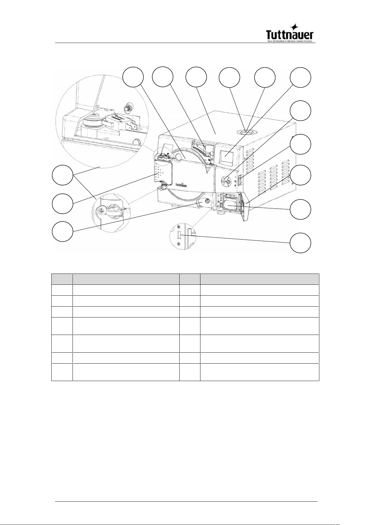
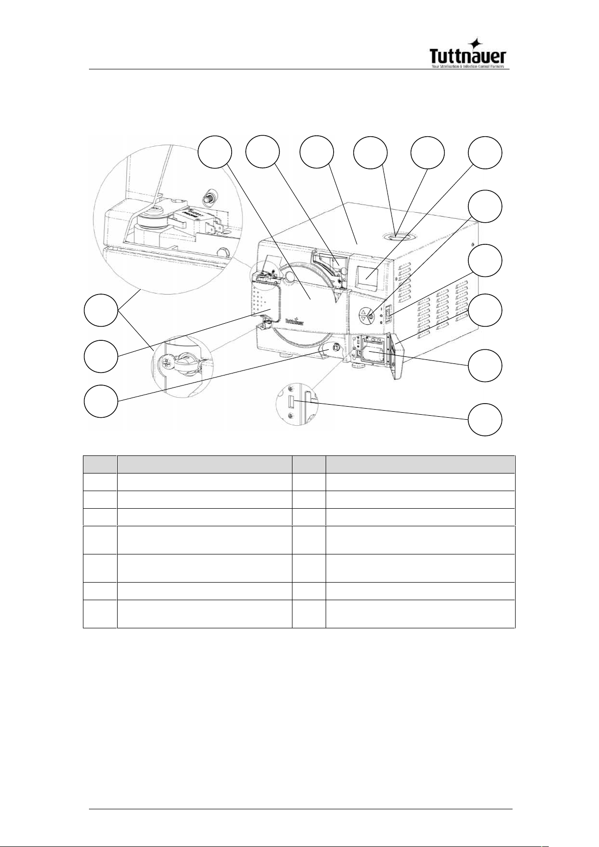
FRONT VIEW – EZ9Plus
No.
Description
No.
Description
1
Reservoir drain
8
Safety valve
2
Door opening grip
9
EZView display
3
Door micro-switches
10
EZPad keypad
4
Door cover
11
Autoclave On/Off switch & circuit
breaker
5
Water reservoir fill & level
gauge
12
Printer cover
6
Autoclave cover
13
Printer (optional)
7
Mineral-free water reservoir
cover
14
USB port
13
2
1
5
4
3
9
10
12
6
7
8
14
11
Page 20
Page 18
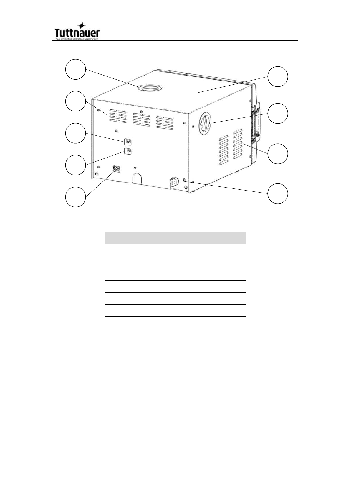
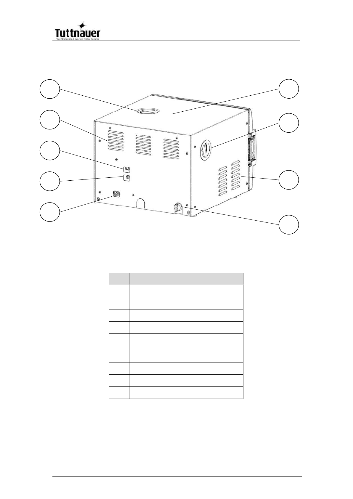
REAR VIEW – EZ9Plus
No.
Description
1
Main power electric cable socket
2
Cut-off thermostat
3
Network port
4
Ventilation grills
5
Mineral-free water reservoir cover
6
Autoclave cover
7
HEPA filter cover
8
Ventilation grills
9
Water outlet strainer
5
4
2
1
6
7
8
3
9
Page 21
Page 19
FRONT VIEW – EZ11Plus
No.
Description
No.
Description
1
Reservoir drain
8
Safety valve
2
Door opening grip
9
EZView display
3
Door microswitches
10
EZPad keypad
4
Door cover
11
Autoclave On/Off Switch &
circuit breaker
5
Water reservoir fill & level
gauge
12
Printer cover
6
Autoclave cover
13
Printer (optional)
7
Mineral-free water reservoir
cover
14
USB port
13
2
1
5
4
3
9
10
12
6
7
8
14
11
Page 22
Page 20
REAR VIEW – EZ11Plus
No.
Description
1
Main power electric cable socket
2
Cut-off thermostat
3
Network port
4
Ventilation grills
5
Mineral-free water reservoir
cover
6
Autoclave cover
7
HEPA filter cover
8
Ventilation grills
9
Water outlet strainer
6
5
4
7
2
1
9
3
8
Page 23
Page 21
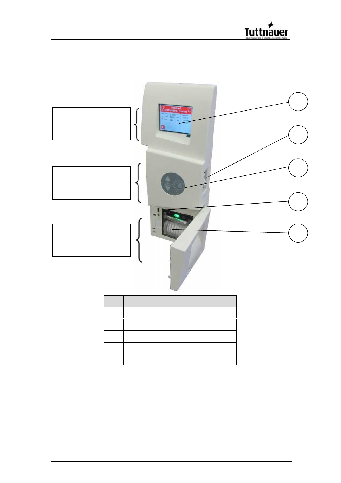
4. CONTROL PANEL
No.
Description
1
EZView display
2
Main switch and circuit breaker
3
EZPad keypad
4
USB port
5
Printer (optional)
1
2
3
4
5
Visual Information
Center
Data Center
Control Center
Page 24
Page 22
4.1. Description and Functions of the Front Panel
The front panel is composed of 3 sections (see picture on
previous page):
1. Visual Information Center
2. Control Center.
3. Data Center
4.1.1. Visual Information Center
The information center contains the EZView display
which is an LCD panel used to display the current
status of the autoclave and any Operational Messages
or Error Messages.
4.1.2. The Control Center
The Control Center contains the ON/OFF switch/Circuit Breaker and the
EZPad keypad.
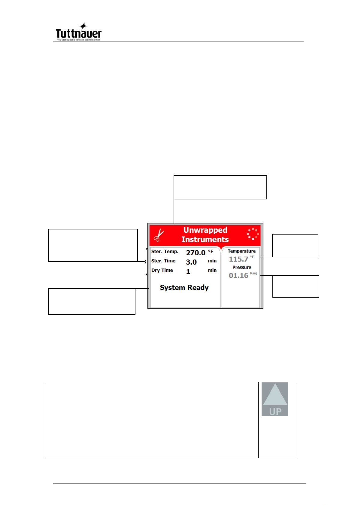
The keypad consists of 3 keys as described below:
UP key
This key has the following functions:
In the main screen:
o This key enables the operator to browse through the
cycles.
In the menu directories:
o When the cursor is blinking on a number, the UP ▲ key
increases its value.
o When the cursor is blinking on a menu selection, the UP
Program description:
Program icon and name
Chamber
temperature
Chamber
pressure
System status
Name of stage
Error and operational messages
Program Parameters:
Sterilization temperature
Sterilization time
Drying Time
Page 25

Page 23
▲ key allows browsing backward through the menu.
o When adjusting a parameter and the cursor is blinking on
SET or EXIT the UP ▲ key activates that procedure.
DOWN key
This key has the following functions:
In the main screen:
o This key enables the operator to browse through the
cycles.
In the menu directories:
o When the cursor is blinking on a number, the DOWN ▼
key decreases its value.
o When the cursor is blinking on a menu selection, the
DOWN ▼ key allows browsing forward through the menu.
o When adjusting a parameter and the cursor is blinking on
SET or EXIT the DOWN ▼ key activates that procedure.
START/STOP key
This key has the following functions:
In the main screen:
o Starts the process when the required program was
chosen.
o Stops the current process.
o Cancels the ERROR message displayed on the screen
and opens the electric door lock.
In the menu directories:
o When the cursor is blinking on a number, the
START/STOP key enables moving to the next position.
o When the cursor is blinking on a menu selection, the
START/STOP key activates that selection.
4.1.3. Data Center
The Data Center contains a USB port, a network port and an
optional printer.
The USB port can be used to upload or download
software and settings and download cycle history for
transferring to a PC for storage or printing.
The network port (located on the rear of the unit) can be
used to connect to a local network and download
information to Tuttnauer’s R.PC.R software.
The RPCR software has been developed especially for the
Tuttnauer autoclaves and is an excellent report generating tool.
This software will allow you to:
Monitor up to 8 autoclaves
Monitor the real time activity of any autoclave connected via
the network port.
Page 26

Page 24
Manage the history files of the cycles run on your autoclave.
The history files can be downloaded either directly through a
physical connection to the network port or transferred
manually using a USB device.
Store all the history of the processes that have been run on
your autoclave
Track the parameter settings that have been used in each of
the cycles and stages run.
Choose the style of the report to view; either graph, table, or a
print out
All reports can be saved as a PDF.
The graph style report offers the user an option to customize
the inputs and outputs used in the presentation.
For more information on the R.PC.R refer to the R.PC.R user
guide.
The printer is an optional device. It prints the detailed history of
each cycle performed by the autoclave. The printing is on
thermal paper with 24 characters per line and records the
sterilization cycle information for subsequent consideration.
4.2. Displayed Error Messages / Symbols
An error message is displayed when a failure occurs. The
failures are divided into two categories.
1. Failures that occur before completing the sterilization stage,
which in this case will leave the load unsterilized
2. Failures that occur after completing the sterilization stage,
which in this case will leave the load sterilized
For the list of Displayed Error Messages / Symbols
see sec. 13 Troubleshooting
Page 27
Page 25
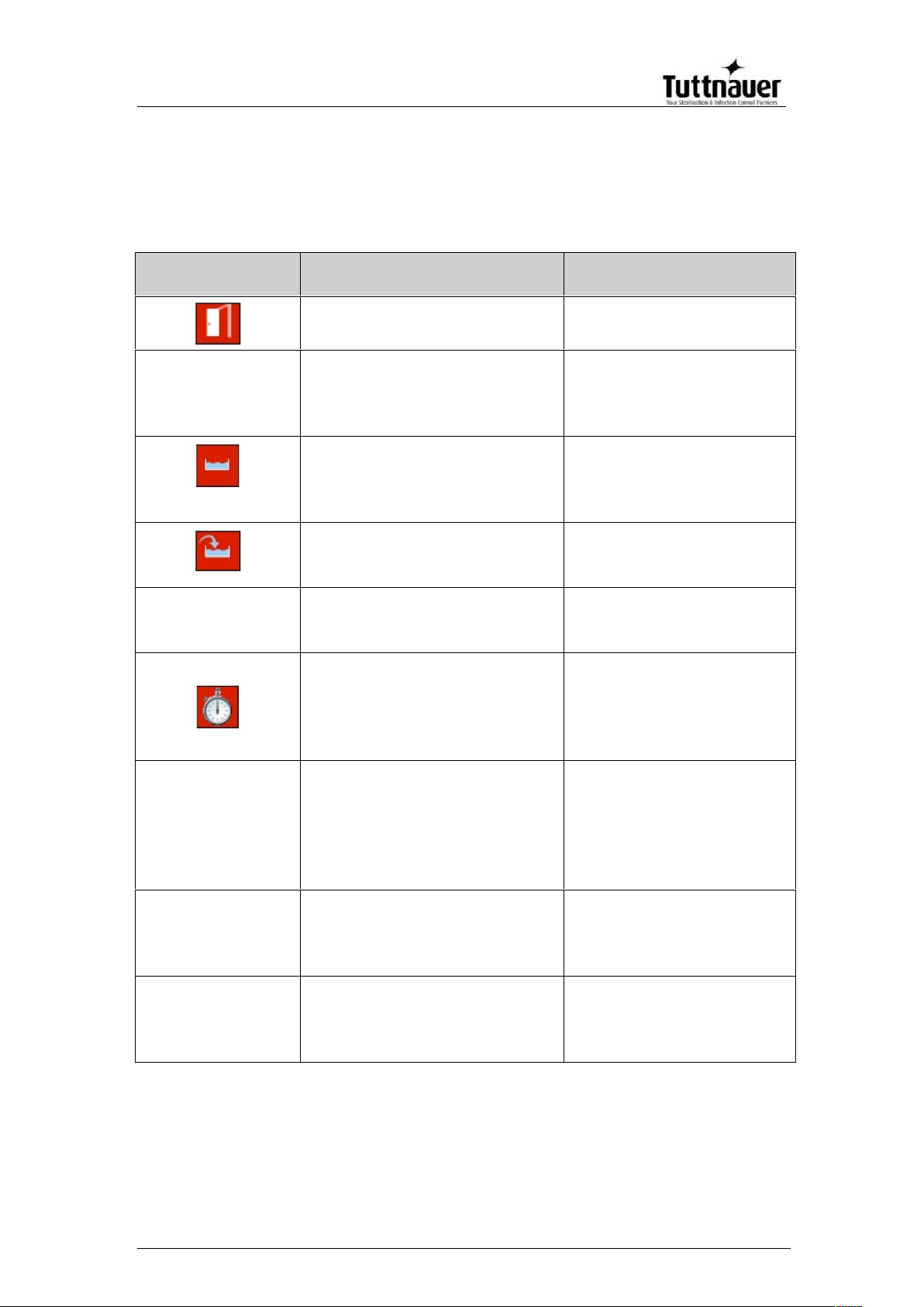
4.3. Displayed operational messages / symbols
Operational messages tell you the status of the machine before or after a
cycle.
Message /
Symbol Name
Message / Symbol
Description
Required Action
This symbol is displayed
when the door is open.
Close the door.
"Door is open"
This message is displayed in
stand-by when the door is
opened and the
START/STOP key is pressed.
Close the door to perform
a new cycle.
If the problem persists,
call the technician.
This message is displayed if
the electrode in the chamber
senses water.
DO NOT open the door,
water will spill out. Run a
new cycle to drain the
chamber.
This symbol is displayed
when there is no water in the
mineral-free water reservoir.
Pour water in the front
funnel until it reaches the
full level.
"Cycle Ended"
This message is displayed
when the cycle has ended
successfully.
Open the door. The
Instruments are ready to
be removed.
This symbol is displayed
when Cycle by Clock mode is
active.
Enter the Quick Options
menu as described in this
manual to change the
time or to cancel this
option.
"Start cycle by
clock is active”
This message is displayed if
the user presses
START/STOP key while the
"start cycle by clock" mode is
active. Starting another cycle
is not allowed.
Enter the Quick Options
menu as described in this
manual to change the
time or to cancel this
option.
"Atmospheric
pressure not set"
This message is displayed
when the ATM needs to be
set.
Opening the door for 2
minutes will allow the
Atmospheric pressure to
be set automatically.
"Please restart
machine in order
for changes to be
updated"
Changes to the system
software require that the
autoclave be restarted.
Restart the autoclave in
order for changes to be
updated.
Page 28
Page 26
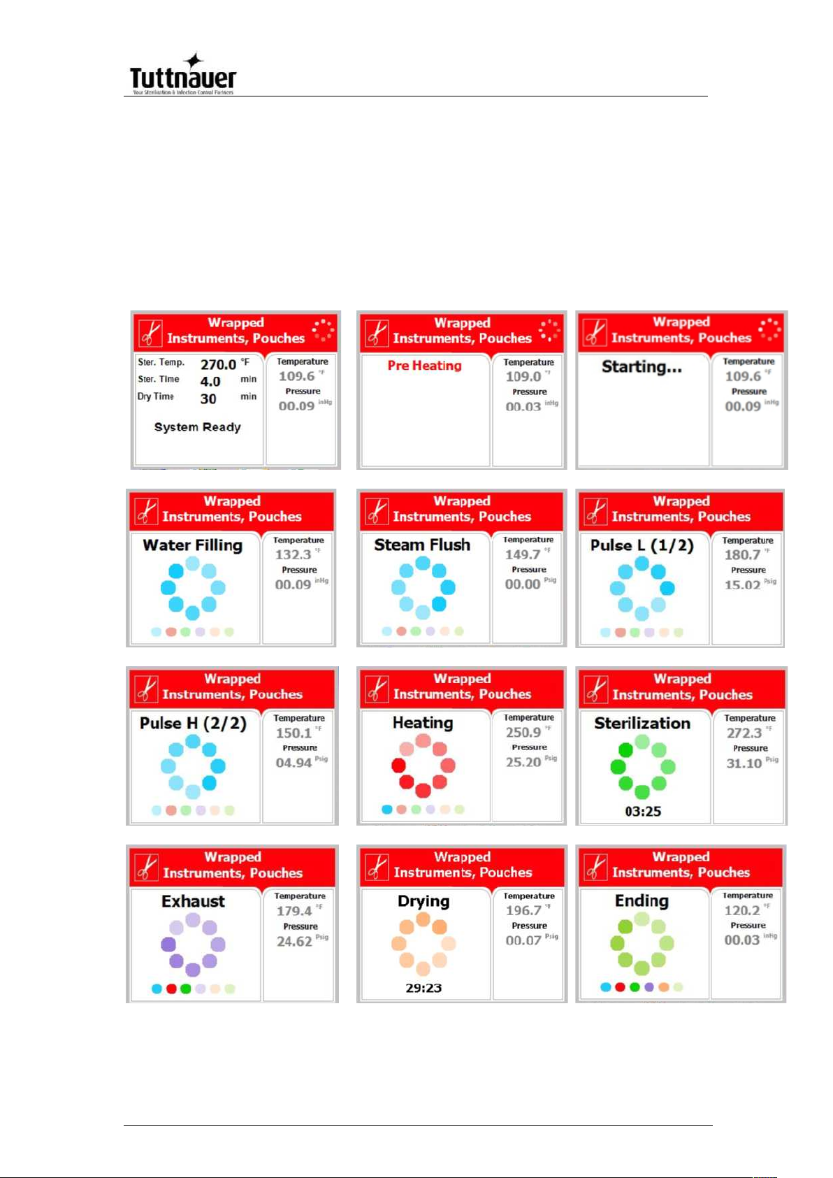
5. EZView SCREENS
During the cycle the EZView screen will change to let you know how the cycle
is progressing. The following screens are a representation of what will be seen
during a cycle.
5.1. Screens showing a successfully completed cycle
1. System Ready
2. Pre-heating
3. Starting
4. Water Filling
5. Steam Flush
6. Pulse L
7. Pulse H
8. Heating
9. Sterilization
10. Exhaust
11. Drying
12. Ending
Page 29
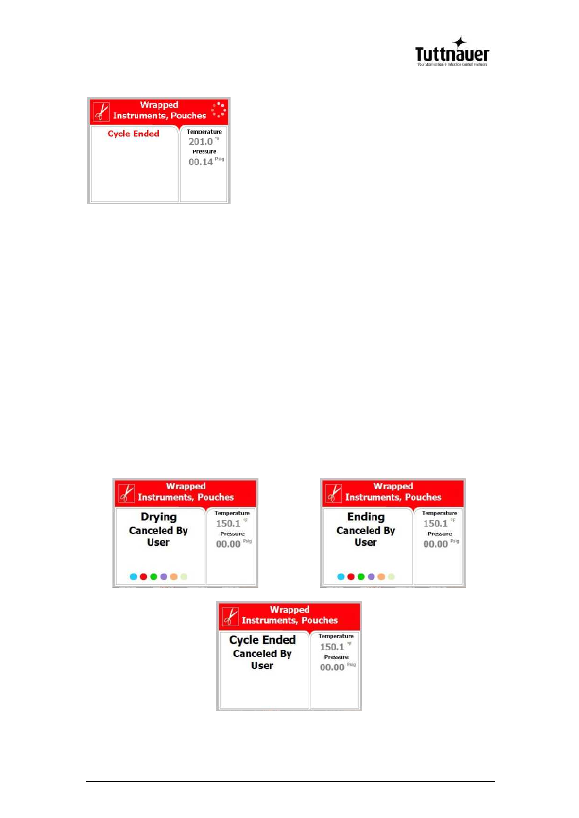
Page 27
13. Cycle Ended (successful
cycle)
5.2. Screens showing aborted cycles AFTER a completed
sterilization stage
The sterilization phase ended successfully – the cycle was
aborted and the reason for the failure is displayed. When the
sterilization portion of the cycle is successful the EZView display
remains white even though the cycle was aborted.
Note: There is a mandatory 1 minute of drying at the end of any
aborted cycle.
The next three scenarios show examples of possible error
messages:
5.2.1. Canceled by user AFTER complete sterilization
stage
The sterilization stage ended successfully, however
the operator manually aborted the remainder of the
cycle, by pressing the START/STOP key. This resulted
in the following sequence of screens showing the
reason for the aborted cycle.
Page 30
Page 28
Note: The user will have to press the START/STOP key, after the mandatory
1 minute drying, to clear the message and unlock the door.
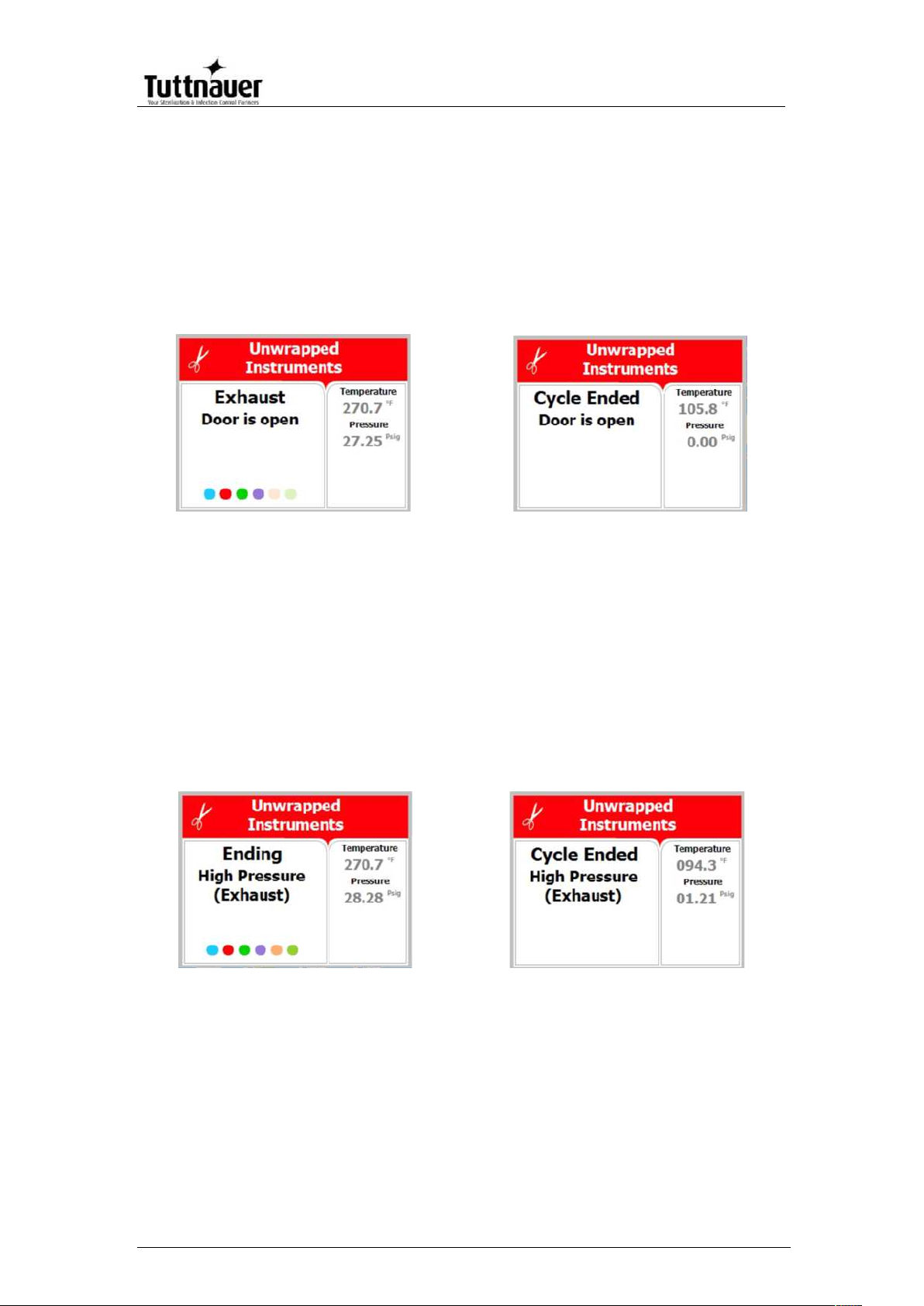
5.2.2. Door is open AFTER the sterilization stage has
finished
The sterilization stage ended successfully, however
the door switch indicated that the door was opened.
This resulted in the following sequence of screens
showing the reason for the aborted cycle.
Note: The user will have to press the START/STOP key, after the mandatory
1 minute drying, to clear the message and unlock the door.
5.2.3. Screens showing a High Pressure Failure AFTER a
completed sterilization stage
The sterilization stage ended successfully, however
the chamber indicated that there was high pressure
during the exhaust phase. This resulted in the
following sequence of screens showing the reason for
the aborted cycle.
Note: The user will have to press the START/STOP key, after the mandatory
1 minute drying, to clear the message and unlock the door.
Page 31

Page 29
5.3. Screens showing a failed cycle:
When the machine fails BEFORE the sterilization phase is
completed the EZView display becomes yellow, a warning sign
and the reason for the failure will appear.
Note: There is a mandatory 1 minute of drying at the end of any
aborted cycle.
An explanation of how the EZView display screen will look when
a cycle has failed:
The next two scenarios show examples of possible error messages:
5.3.1. Screens showing a failure because of a Heat Time
Error
The machine was not able reach the proper
temperature. This resulted in the following sequence of
screens showing the reason for the aborted cycle.
Note: The user will have to press the START/STOP key, after the mandatory
1 minute drying, to clear the message and unlock the door.
Cycle failed
Reason of failure
Warning symbol
The screen color
changed from white to
yellow
Page 32

Page 30
5.3.2. Failure due to Cancellation by user BEFORE
completing the sterilization stage
Note: The user will have to press the START/STOP key, after the mandatory
1 minute drying, to clear the message and unlock the door.
Page 33

Page 31
6. STERILIZATION PROGRAMS
The control system incorporates a safety feature that prevents
changing programs if the door is closed.
This protection is intended to prevent running an inappropriate program
if the autoclave is loaded, but the cycle is not immediately started.
If the operator for example inserts the load into the chamber, closes the
door and leaves the room and another operator/user tries to change
the program, the operator/user will not be able to do this unless the
door is opened and the type of load inside the chamber can be seen.
The autoclave offers four preset FDA cleared sterilization programs, a
dedicated cleaning program (for cleaning the chamber using Chamber
Brite), a calibration program (for use by a technician) and two custom
programs. The custom programs are not FDA cleared and it is the
user’s responsibility to validate these programs.
Spore testing is your only assurance of complete sterilization.
Using the UP OR DOWN keys enables the user to select the various
programs as seen in the following list:
Sterilization Programs
Temp
Sterilization
time
(minutes)
Dry time
(minutes)
Program
Icon
Description
1
Unwrapped
Instruments
270°F
(132°C)
3
1 (default)
Range: 1-99
2
Wrapped
Instruments,
Pouches
270°F
(132°C)
4
30 (default)
Range: 30-99
3
Unwrapped
Delicate
Instruments
250°F
(121°C)
30
1 (default)
Range: 1-99
4
Handpieces
270°F
(132°C)
4
30 (default)
Range: 30-99
5
Chamber
Brite
Cleaning
270°F
(132°C)
3
Keep
temperature
0 (default)
6
Calibration
cycle
270°F
(132°C)
15
1
Page 34

Page 32
7
Extra Drying
Time
5
8
Custom A
270°F
(132°C)
4
30 (default)
Range: 0-99
9
Custom B
250°F
(121°C)
30
1 (default)
Range: 0-99
During the process, the various stages of the cycle will be displayed on
the screen, as shown in this example and in sec. 5.1.
The user should use only those sterilizer accessories
(Biological Indicators, Chemical Indicators. etc.) that have
been cleared by the FDA for the specific cycle time and
temperature of this device.
The stages names are as follows:
Starting
Water Filling
Steam Flush
Pulse L
Pulse H
Heating
Sterilization
Exhaust
Drying
Ending
Page 35

Page 33
6.1. Program 1: Unwrapped Instruments
For unwrapped instruments and materials, when the instrument
manufacturer recommends autoclaving at temperatures of 270F
(132C) and no drying stage is required.
Nominal parameters default settings
Sterilization temperature: 270F (132C)
Sterilization time: 3 minutes.
Drying time: 1 minute (may be increased by the operator (see
sec. 7.1.1), other parameters are set and cannot be altered).
Operations Sequence
Automatic water fill into the chamber and heating by actuation
of electrical heaters until completion of the steam flush
process.
Positive air-removal pulses in the EZ11Plus to complete
removing air from the chamber (not applicable to the EZ9Plus
in this program).
Heating by actuation of electrical heaters until the sterilization
temperature is reached.
Sterilization temperature is maintained constant for the preset
sterilization time.
Fast exhaust, steam is exhausted out of the chamber at a fast
rate until pressure decreases to ambient pressure.
Drying for 1 minute to remove residual steam from the
chamber.
CAUTION!
The sterility of instruments processed in unwrapped cycles
cannot be maintained if exposed to non-sterile
environment.
Page 36

Page 34
6.2. Program 2: Wrapped Instruments, Pouches
For wrapped instruments, pouches and materials, when the
instrument manufacturer recommends autoclaving at
temperatures of 270F (132C) with a drying stage.
Nominal parameters default settings
Sterilization temperature: 270F (132C)
Sterilization time: 4 minutes
Drying time: 30 minutes (may be increased by the operator
(see sec. 7.1.1), other parameters are set and cannot be
altered).
Operations sequence:
Automatic water fill into the chamber and heating by actuation
of electrical heaters until completion of the steam flush
process.
Positive air-removal pulses to complete removing air from the
chamber.
Heating by actuation of electrical heaters until the sterilization
temperature is reached.
Sterilization temperature is maintained constant for the preset
sterilization time.
Fast exhaust, steam is exhausted out of the chamber at a fast
rate until pressure decreases to ambient pressure.
Drying by heating of chamber and air circulation to remove
leftover moisture from the instruments and wraps.
Page 37

Page 35
6.3. Program 3: Unwrapped Delicate Instruments
For unwrapped delicate instruments, when the instrument
manufacturer recommends autoclaving at temperatures of 250F
(121C) and no drying stage is required.
Nominal parameters default settings
Sterilization temperature: 250ºF (121ºC)
Sterilization time: 30 minutes.
Drying Time: 1 minute (may be increased by the operator (see
sec. 7.1.1), other parameters are set and cannot be altered).
Operations sequence:
Automatic water fill into the chamber and heating by actuation
of electrical heaters until completion of the steam flush
process.
Positive air-removal pulses in the EZ11Plus to complete
removing air from the chamber (not applicable to the EZ9Plus
in this program).
Heating by actuation of electrical heaters until the sterilization
temperature is reached.
Sterilization temperature is maintained constant for the preset
sterilization time.
Fast exhaust, steam is exhausted out of the chamber at a fast
rate until pressure decreases to ambient pressure.
Drying for 1 minute to remove residual steam from the
chamber.
CAUTION!
The sterility of instruments processed in unwrapped cycles
cannot be maintained if exposed to non-sterile
environment.
Page 38

Page 36
6.4. Program 4: Handpieces
For wrapped Handpieces when the instrument manufacturer
recommends autoclaving at temperatures of 270F (132C) with
a drying stage.
Note: Tuttnauer recommends all Handpieces be wrapped for
sterilization.
Nominal parameters default settings
Sterilization temperature: 270F (132C).
Sterilization time: 4 minutes.
Drying time: 30 minutes (may be increased by the operator
(see sec. 7.1.1), other parameters are set and cannot be
altered).
Operations Sequence
Automatic water fill into the chamber and heating by actuation
of electrical heaters until completion of the steam flush
process.
Positive air-removal pulses to complete removing air from the
chamber.
Heating by actuation of electrical heaters until the sterilization
temperature is reached.
Sterilization temperature is maintained constant for the preset
sterilization time.
Fast exhaust, steam is exhausted out of the chamber at a fast
rate until pressure decreases to ambient pressure.
Drying by heating of chamber and air circulation to remove
leftover moisture from the instruments and wraps.
Page 39

Page 37
6.5. Program 5: Chamber Brite Cleaning
This is a maintenance cycle used with Tuttnauer’s Chamber
Brite
TM
cleaner for cleaning the chamber and piping of the
autoclave. We recommend using Chamber BriteTMand cleaning
the autoclave every 20 cycles or once per week whichever is
longer. (see sec. 12.1.2 for detailed instruction on cleaning the
chamber).
CAUTION! This is not a sterilization program! This program
has not been cleared by the FDA for sterilization.
Nominal parameters default settings
Cleaning temperature: 270F (132C).
Cleaning time: 3 minutes.
Operations sequence:
Automatic water fill into the chamber and heating by actuation
of electrical heaters until completion of the steam flush
process.
Heating by actuation of electrical heaters until the cleaning
temperature is reached.
Cleaning temperature is maintained constant for the preset
cleaning time.
Fast exhaust, steam is exhausted out of the chamber at a fast
rate until pressure decreases to ambient pressure.
No Drying
The turquoise color of the screen, when the cycle is running,
is intended to remind the user that the program is not a
sterilization program.
Page 40

Page 38
6.6. Program 6: Calibration Cycle
This program is only for use by a technician with the proper test
equipment to aid in calibrating the autoclave. This is a shortened
cycle with a long sterilization phase at 270F (132C) and no
drying to facilitate the calibration process.
CAUTION! This is not a sterilization program! This program has
not been cleared by the FDA for sterilization.
Nominal parameters default settings
Calibration temperature: 270F (132C)
Calibration time: 15 minutes.
Drying time: 1 minute is the minimum value set when no
drying is required.
Operations Sequence
Automatic water fill into the chamber and heating by actuation
of electrical heaters until completion of the steam flush
process.
Positive air-removal pulses to complete removing air from the
chamber
Heating by actuation of electrical heaters until the calibration
temperature is reached.
Calibration temperature is maintained constant for the preset
calibration time.
Fast exhaust, steam is exhausted out of the chamber at a fast
rate until pressure decreases to ambient pressure.
Drying for 1 minute to remove residual steam from the
chamber.
Page 41

Page 39
6.7. Program 7: Extra Drying Time
For all loads, when the load requires additional drying after the
cycle is completed.
Nominal parameters default settings
Drying time: 5 minute (may be changed by the operator (see
sec. 7.1.1)).
Operations Sequence
Drying for 5 minutes.
Page 42

Page 40
6.8. Program 8: Custom A (may be altered by the user)
This program allows the user to adjust all cycle parameters in
order to sterilize items that cannot be sterilized in any of the
preceding default programs.
This is not an FDA cleared program and validation of
sterility when using this program is the responsibility of the
user.
See section 7 for instructions on how to create a custom
program.
Nominal parameters default settings
Sterilization temperature: 270°F (132°C).
Sterilization time: 4 minutes.
Drying time: 30 minutes
Operations sequence:
Automatic water fill into the chamber and heating by actuation
of electrical heaters until completion of the steam flush
process.
Positive air-removal pulses to complete removing air from the
chamber.
Heating by actuation of electrical heaters until the sterilization
temperature is reached.
Sterilization temperature is maintained constant for the preset
sterilization time.
Fast exhaust, steam is exhausted out of the chamber at a fast
rate until pressure decreases to ambient pressure.
Drying by heating of chamber and air circulation to remove
leftover moisture from the instruments and wraps.
Page 43

Page 41
6.9. Program 9: Custom B (may be altered by the user)
This program allows the user to adjust all cycle parameters in
order to sterilize items that cannot be sterilized in any of the
preceding default programs.
This is not an FDA cleared program and validation of
sterility when using this program is the responsibility of the
user.
See section 7 for instructions on how to create a custom
program.
Nominal parameters default settings
Sterilization temperature: 250F (121C).
Sterilization time: 30 minutes.
Drying time: 1 minute.
Operations sequence:
Automatic water fill into the chamber and heating by actuation
of electrical heaters until completion of the steam flush
process.
Positive air-removal pulses to complete removing air from the
chamber.
Heating by actuation of electrical heaters until the sterilization
temperature is reached.
Sterilization temperature is maintained constant for the preset
sterilization time.
Fast exhaust, steam is exhausted out of the chamber at a fast
rate until pressure decreases to ambient pressure.
Drying for 1 minute to remove residual steam from the
chamber.
Page 44

Page 42
7. CHECKING AND CHANGING PARAMETERS AND OTHER
DATA
This section shows how to access system data and modify parameters.
The Cycle Parameters directory containing parameters for controlling
the sterilization process is locked for programs 1 thru 4 and not
available for modification from the default values (except for drying).
Program 5 is a cleaning program and all parameters are locked.
Program 6 is a calibration program for use by a technician and all
parameters are locked.
Two programs are available for the user to modify as needed, Custom
A and Custom B. These custom programs are not FDA cleared and it is
the users responsibility to validate these programs.
Spore testing is your only assurance of complete sterilization.
Once entering the programming mode, the operator will see and have
access to the following directory items.
Directory
Subdirectory
Quick Options see sec. 7.1
Add extra dry time
Export to USB
Print cycles
Version information
Start cycle by clock
Set date and time
Login
Exit
Main Menu
(requires
login) see
sec. 7.2
Cycle
Parameters –
applicable
only for
Custom
programs
(except Dry
Time) See
sec. 7.2.1
Cycle Parameters
System
Parameters
See sec. 7.2.3
Print Rate All
Print Rate Sterilization
Screen Saver
Cycle Print Gap
Maintenance
See sec. 7.2.4
Export gain and offset to USB
Reset atmospheric pressure
Printer test
Print all gain and offset
Page 45

Page 43
7.1. Quick Options Directory
To take advantage of the system features it is necessary to access the
programming mode. Some subdirectories enable the operator to see
and change an individual cycle’s parameters. Therefore it is necessary
to choose the required cycle before entering the programming mode.
1. Enter the programming mode by pressing the UP and DOWN
keys simultaneously for 1-2 seconds. When released the “Quick
Options” screen will be displayed. Scroll up or down the list and
press the START/STOP key to select.
Some features will require an access code. The operator’s access
code is 0001.
2. To exit this screen or any screen in this section, press the UP or
DOWN key to move the cursor to Exit and press START/STOP
key.
7.1.1. Add extra dry time
Accessing this parameter allows the operator to ADD
additional drying time to the default drying time of the
cycle selected.
As an example: If the program default is 30 minutes
drying selecting 10 additional minutes will give a total
drying time of 40 minutes. The additional drying time
will remain as part of the cycle until changed back. To
return to the original 30 minutes, select 0 additional
minutes, now the total drying time will be 30 minutes.
Scroll up or down the list and press the START/STOP
key to select.
Page 46

Page 44
7.1.2. Export to USB
Note: The USB flash drive needs to use FAT formatting.
Scroll up or down the list and press the START/STOP
key to select.
1.Export current version to USB
Accessing the Export current version feature allows
the operator to export the machines current
application for evaluation by a technician.
a.Insert the USB device into the USB Socket
located behind the printer door (See Sec. 4)
b.Move the cursor to Export current version to
USB device.
c.Press the START/STOP key
The following screen will be displayed:
Page 47

Page 45
2.Export all settings to USB
Accessing the Export all settings feature allows the
operator to export all the machines cycle settings for
evaluation by a technician using Tuttnauer’s R.PC.R
software.
a.Insert the USB device into the USB Socket
located behind the printer door (See Sec. 4)
b.Move the cursor to Export all settings to USB
device.
c.Press the START/STOP key
The following screen will be displayed:
3.All cycle history
4.Last 10 cycles
5.Last 50 cycles
Accessing the export cycle history feature allows the
operator to export cycle history of the previous 100
cycles to a USB device for evaluation or digital
storage. Cycle data is exported in individual text file
Page 48

Page 46
format (.txt) for viewing on a PC or with Tuttnauer’s
R.PC.R software. Exporting the cycle history will not
automatically delete the cycle history.
a.Insert the USB device into the USB socket
located behind the printer door (see sec. 4)
b.Move the cursor to select the number of
cycles to export
c.Press the START/STOP key.
The following screen will be displayed.
7.1.3. Print cycles
Select this option and the following screen will be displayed.
This subdirectory offers the following options:
Print last cycle
Print last 5 cycles
Print last 10 cycles
Page 49

Page 47
The Print cycles feature requires that the machine have a
printer installed. This feature allows the operator to print
out the last cycle, the last 5 cycles or the last 10 cycles.
Scroll down to the desired option and press the
START/STOP key. Once the printer has finished scroll to
Exit and pressing the START/STOP key will return to the
main screen
7.1.4. Version information
This subdirectory allows viewing of the current version of
software running the machine.
Select this option and the following screen will be
displayed.
7.1.5. Start cycle by clock
This option allows for scheduling the selected cycle to
start at a later time (The maximum possible delay is 24
hours). No other program can be run while the Start
Cycle by Clock is active.
Select this option and the following screen will be
displayed:
Page 50

Page 48
The time is displayed in the form “HH:MM”. The time is
in a 24 hour format (i.e. 14:30 = 2:30 PM).
Enabling the Start Cycle By Clock
1. Select the cycle to be scheduled from the Main
Screen before enabling this option.
2. Set the start time by using the UP and DOWN
keys to change the blinking digit. Use the
START/STOP key to move to the next digit.
3. Use the START/STOP key to move the cursor to
Enable.
4. Use the UP or DOWN key to select Enable.
5. Use the START/STOP key to move the cursor to
exit.
6. Use the UP or DOWN key to exit.
7. The cycle is now enabled.
Note: When Start Cycle by clock is enabled this icon
will be displayed on the main screen.
Once the cycle has run the option will automatically
return to disabled
Page 51

Page 49
Cancelling the Start Cycle By Clock
Select the Start Cycle by Clock option from the Quick
Options menu.
1.Use the START/STOP key to move the cursor to
Disable
2.Use the UP or DOWN key to select Disable
3.Use the START/STOP key to move the cursor to exit
4.Use the UP or DOWN key to exit.
5.The cycle is now disabled.
7.1.6. Set date and time
Note: It is important to set the date and time when setting
up a new machine for the first time.
The internal battery is turned off for shipping. Setting the
date and time will restart that battery.
Note: Failure to set the Date and Time will cause a Time
Error and the unit will not run properly.
This option enables the operator to set the date and time.
The following screen will be displayed:
Page 52

Page 50
The time is displayed in the upper row in the form
“HH:MM”. The time is in a 24 hour format (i.e.
14:30 = 2:30 PM)
To set the time use the UP and DOWN keys to
change the blinking digit. Use the START/ STOP
key to move to the next digit.
The date is displayed in the lower row in the form
“DD/MMM/YYYY” (e.g. 05/APR/2012)
To set the date use the UP and DOWN keys to
change the blinking digit. Use the START/ STOP
key to move to the next digit.
When all changes are completed, use the START/
STOP key to move to SET, then use the UP or
DOWN key to save the new date and time.
When saving is completed, the Set Date and Time
screen is still displayed.
Move the cursor to Exit and press the UP or DOWN
key.
Selecting exit will return to the Main screen where
the next option can be selected.
Note: After setting time and date, the autoclave will
restart automatically.
7.1.7. Login
Accessing additional feature requires entering a
password, follow these steps
1. Select Login and press the START/STOP key.
2. The SELECT USER screen is displayed
Page 53

Page 51
3. Move the cursor to User, if it is not already
highlighted, and press START/STOP key
4. Enter Code screen is now displayed
5. 0000 is displayed on the screen with the cursor
blinking on the right digit.
6. To increase or decrease the right digit, press the
UP or DOWN keys.
7. Change the code to 0001 and move the cursor to
SET by pressing the START/STOP key four
times.
8. When SET is blinking, press the UP or DOWN key
to enter the MAIN MENU screen.
The following screen is displayed:
Page 54

Page 52
See section 7.2 for more details on the MAIN MENU.
7.1.8. Exit
Selecting Exit and pressing the START/STOP key, will
bring you back to the main screen.
7.2. Main Menu
1. To browse through the subdirectories, use the UP and
DOWN keys.
2. When the desired directory is blinking, press the
START/STOP key. The required screen (see the following
paragraphs) will be displayed.
3. To exit the MAIN MENU screen, press the UP or DOWN key
to move the cursor to EXIT and then press START/STOP.
4. An explanation of the various directories, subdirectories and
parameters can be found on the following pages.
Page 55

Page 53
7.2.1. Cycle Parameters for Custom A and B cycles
This directory enables the operator to see and change all the
cycle parameters for Custom A and Custom B cycles. To modify
a program it is necessary to select that program from the Main
Screen before entering the "MAIN MENU" directory
This directory includes seven subdirectories. A description of
each parameter can be found in see section 7.3
Subdirectory
Property
Create Pulse
Pulse A Count
Pulse A Stay Time
Pulse A Low Pressure
Pulse A High Pressure
Pulse B Count
Pulse B Stay Time
Pulse B Low Pressure
Pulse B High Pressure
Pulse C Count
Pulse C Stay Time
Pulse C Low Pressure
Pulse C High Pressure
Pulse D Count
Pulse D Stay Time
Pulse D Low Pressure
Pulse D High Pressure
Heating
Sterilization Temperature
Sterilization
Sterilization Temperature
Sterilization Time
Exhaust
Exhaust Mode
Drying
Dry Time
Dry Heat On 1
Dry Heat Off 1
Dry first stage time
Dry Heat On 2
Dry Heat Off 2
Additional Dry Time
Ending
End Temperature
Global
Jacket Temperature
Page 56

Page 54
7.2.2. Modifying a parameter for the Custom A and B
cycles
In the following example Pulse A Count will be modified
1. Using the UP or DOWN keys select the Custom A
program from the Main Screen.
2. Enter the programing mode by pressing the UP
and DOWN keys simultaneously for 1-2 seconds
and then release.
3. Login using the User code 0001.
4. Select Cycle Parameters (Custom A) from the
Main Menu.
Page 57

Page 55
5. Use the UP or DOWN keys to move to the Create
Pulse subdirectory as shown in the table in sec.
7.2.1. Pressing the START/STOP key will allow
the user to enter that subdirectory.
6. Pressing the START/STOP key again will select
the individual parameter for modification.
Page 58

Page 56
7. The Set Parameter screen will appear as shown
with the current parameter setting highlighted.
This screen is representative of a typical Set Parameter
screen.
The Set Parameter screen shows the name of the
parameter to be changed; it shows the maximum,
minimum, and default values for this parameter. It also
shows the current parameter setting.
8. Use the UP and DOWN keys to change the
desired value. See the table in sec. 7.3 to
determine the appropriate value to use.
9. Use the START/STOP key to advance the
blinking cursor to SET. Use UP or DOWN key to
enter the new value.
10. Selecting SET or EXIT will return you to the
previous screen where the next parameter can be
selected for modification.
11. Selecting EXIT before selecting SET will return to
the previous screen without changing the
parameter.
The custom programs are not FDA cleared
and it is the user’s responsibility to validate
any custom cycles
Spore testing is your only assurance of
complete sterilization.
7.2.3. System Parameters
This directory allows for the modification of four
parameters. These parameters apply to all programs.
Page 59

Page 57
Print Rate all – defines the printing rate during all
stages of the cycle except the sterilization stage.
This feature requires a printer to be installed.
Print Rate Sterilization – Defines the printing rate
during the sterilization stage. This feature requires
a printer to be installed.
Screen Saver – defines the time interval from the
last use of the Keypad until the screen saver is
activated. Setting this parameter to 0 minutes will
disable the screen saver.
Cycle Print Gap – Defines the number of blank
lines to advance at the end of the cycle. This
feature requires a printer to be installed.
Modifying a system parameter
Every parameter can be changed as follows:
1. Select any program to modify the System
Parameters
2. Enter the programing mode by pressing the UP
and DOWN keys simultaneously for 1-2 seconds
and then release.
3. Login using the User code 0001
4. Select System Parameters from the Main Menu
and press the START/STOP key. The System
Parameters screen will appear.
Page 60

Page 58
5. Use the UP or DOWN keys to move to the
appropriate parameter from the system
parameters screen.
6. Use the START/STOP key to select this
parameter. The set parameter screen will appear.
Page 61

Page 59
The Set parameter screen shows the name of the
parameter to be changed; it shows the maximum,
minimum, and default value for this parameter. It also
shows the current parameter setting.
7. Use the UP and DOWN keys to change the
desired value.
8. Use the START/STOP key to advance the
blinking cursor to SET. Use UP or DOWN key to
enter the new value.
9. Selecting SET or EXIT will return you to the
previous screen where the next parameter can be
selected for modification.
10. Selecting EXIT before selecting SET will return to
the previous screen without changing the
parameter.
7.2.4. Maintenance
This directory offers the following options. These options apply
to all programs.
1. Select any program from the Main Screen to
access the Maintenance options.
2. Enter the programing mode by pressing the UP
and DOWN keys simultaneously for 1-2 seconds
and then release.
3. Login using the User code 0001
4. Select Maintenance from the Main Menu and
press the START/STOP key.
The following screen will appear:
Page 62

Page 60
5. Use the UP or DOWN keys to move to the
appropriate option from the maintenance screen.
6. Use the START/STOP key to select this option.
The screen for that option will appear (see the
screens for each option in the following sections).
7.2.4.1.Export Gain and Offset to USB
This option allows for exporting the gain and offset to a USB
flash drive. This information is for use by a factory engineer.
Note: The USB flash drive needs to use FAT formatting.
1. Insert the USB device into the USB Socket located
behind the printer door. (See sec. 4 ).
2. Move the cursor to Export gain offset to USB
3. Press the START/ STOP key.
The following screen will be displayed:
4. Remove the USB device from the USB socket.
Page 63

Page 61
To exit this screen and return to Maintenance screen press
the START/ STOP key.
7.2.4.2.Reset atmospheric pressure
This is an option to manually reset the Atmospheric
pressure parameter.
Note: The atmospheric pressure parameter is set
automatically, however this parameter can be manually
reset by using this option.
In order to reset the atmospheric pressure make sure
the door is open and the chamber temperature is less
than 113ºF.
Move the cursor to Reset atmospheric pressure then
press the START/ STOP key.
The following screen will be displayed:
In order to exit this screen, press the START/ STOP key.
7.2.4.3.Printer Test (for units with an optional printer)
This option enables the operator to test the printer
The printer will provide the following print out:
Page 64

Page 62
When the printer has finished, the following screen will
be displayed:
Page 65

Page 63
In order to exit this screen, press the START/STOP key.
7.2.4.4.Print All Gain and Offset (for units with an optional
printer)
This option allows for printing all the gain and offset
values. This information is for use by a factory engineer.
The printer will provide gain and offset for the following:
Chamber temperature
Chamber Pressure
Chamber water level
Mineral free Water Level
The following screen will be displayed:
In order to exit this screen press the START/ STOP key.
Page 66

Page 64
7.3. Table of Parameters
This option is only available for the Custom A and Custom
B programs.
This table describes the function of each of the parameters that
control the different parts of the sterilization cycle. Each
parameter is available for modification by the user.
The default values shown in this table apply only to the Custom
B program.
To modify a different program it is necessary to select that
program before entering the "MAIN MENU" directory
Custom A and Custom B programs are not FDA cleared.
It is the user’s responsibility to validate any Custom cycles.
This device utilizes the Steam Flush Pressure Pulse technology
for removing air from the chamber prior to sterilization. The
Create Pulse parameters are what control this process.
Inappropriate parameter modification can affect the quality of the
sterilization process.
Spore testing is your only assurance of
complete sterilization.
Parameters
Subdirectory
Description
Default
Units
Range
Resolution
Pulse A
Count
Create Pulse
Defines the number
of pulses in the first
pulse group (group
A)
2
Whole
Number
0-10
1
Pulse A Stay
Time
Defines the
additional time that
the top exhaust
valve will remain
open after reaching
the pressure set by
the Pulse A low
Pressure parameter
in the first pulse
group.
10
Seconds
1-100
1
Pulse A Low
Pressure
Defines the
pressure that the
top exhaust valve
closes at the bottom
of each pulse.
18.85
Psia
0.73 –
43.51psia
.01
Page 67

Page 65
Parameters
Subdirectory
Description
Default
Units
Range
Resolution
Pulse A High
Pressure
Defines the
pressure that the
top exhaust valve
opens at the top of
each pulse.
26.10
Psia
0.73 –
43.51psia
.01
Pulse B
Count
Defines the number
of pulses in pulse
group B.
0
Whole
Number
0-10
1
Pulse B Stay
Time
Defines the
additional time that
the top exhaust
valve will remain
open after reaching
the pressure set by
the Pulse B Low
Pressure parameter
in group B.
2
Seconds
1-100
1
Pulse B Low
Pressure
Defines the
pressure at which
the top exhaust
valve closes at the
bottom of each
pulse.
26.11
Psia
0.73 –
43.51psia
.01
Pulse B High
Pressure
Defines the
pressure at which
the top exhaust
valve opens at the
top of each pulse.
29.01
Psia
0.73 –
43.51psia
.01
Pulse C
Count
Create Pulse
Defines the number
of pulses in pulse
group C.
0
Whole
Number
0-10
1
Pulse C Stay
Time
Defines the
additional time that
the top exhaust
valve will remain
open after reaching
the pressure set by
the Pulse C low
Pressure parameter
in pulse group C.
10
Seconds
1-100
1
Page 68

Page 66
Parameters
Subdirectory
Description
Default
Units
Range
Resolution
Pulse C Low
Pressure
Defines the
pressure that the
top exhaust valve
closes at the bottom
of each pulse.
23.20
Psia
0.73 –
43.51psia
.01
Pulse C High
Pressure
Defines the
pressure that the
top exhaust valve
opens at the top of
each pulse.
26.11
Psia
0.73 –
43.51psia
.01
Pulse D
Count
Defines the number
of pulses in pulse
group D.
0
Whole
Number
0-10
1
Pulse D Stay
Time
Defines the
additional time that
the top exhaust
valve will remain
open after reaching
the pressure set by
the Pulse D low
Pressure parameter
in pulse group D.
10
Seconds
1-100
1
Pulse D Low
Pressure
Defines the
pressure that the
top exhaust valve
closes at the bottom
of each pulse.
23.20
Psia
0.73 –
43.51psia
.01
Pulse D High
Pressure
Defines the
pressure that the
top exhaust valve
opens at the top of
each pulse.
26.11
Psia
0.73 –
43.51psia
.01
Sterilization
Temperature
Heating
Defines the
temperature that
needs to be reached
during heating in
order to get to the
sterilization stage.
250ºF
ºF
212 ºF-
284 ºF
0.5°
Sterilization
Temperature
Sterilization
Defines the
temperature that
needs to be
maintained during
sterilization.
250ºF
°F
212 ºF-
284 ºF
0.5°
Page 67
Page 69

Parameters
Subdirectory
Description
Default
Units
Range
Resolution
Sterilization
Time
Defines the length
of time the
sterilization
temperature and
pressure must be
held.
30
Minutes
0-9999
0.5
Exhaust
Mode
Exhaust
This parameter
allows four choices;
1. Fast Exhaust
2. Fast Exhaust if
the chamber
pressure is less
than atmospheric
+ 4.5psi,
otherwise Slow
Exhaust
3. Slow Exhaust
4. Slow Exhaust if
the chamber has
not completed
sterilization,
otherwise Fast
Exhaust.
1
Whole
Number
1-4
1
Dry Time
Drying
Defines the total
length of the drying
cycle.
1
Minutes
0-99
1
Dry heat
On 1
Defines the ON time
portion of the duty
cycle for the heating
elements during the
first stage of the
drying cycle.
4
Seconds
0-120
1
Dry Heat Off
1
Defines the OFF
time portion of the
duty cycle for the
heating elements
during the first stage
of the drying cycle.
12
Seconds
0-120
1
Page 70

Page 68
Parameters
Subdirectory
Description
Default
Units
Range
Resolution
Dry First
Stage Time
The total drying
cycle can be divided
into two stages. This
parameter defines
the length of the first
stage. The second
stage will start at the
end of the first and
last until the end of
the total drying
cycle.
10
Minutes
0-120
1
Dry Heat On
2
Defines the ON time
portion of the duty
cycle for the heating
elements during the
second stage of the
drying cycle.
4
Seconds
0-120
1
Dry Heat Off
2
Defines the OFF
time portion of the
duty cycle for the
heating elements
during the second
stage of the drying
cycle.
10
Seconds
0-120
1
Additional
Dry Time
Defines the number
of additional
minutes to add to
the default dry time
0
Minutes
0-60
1
End
Temperature
Ending
Define the
temperature at the
end of the cycle that
must be achieved
before the cycle can
end and the door be
opened.
248°F
°F
86°F-
302°F
1
Page 71

Page 69
Parameters
Subdirectory
Description
Default
Units
Range
Resolution
Jacket
Temperature
Global
This defines the
chamber pre-heat
temperature for the
program selected. It
is not recommended
to go above 120ºF.
Too high a
temperature will
damage the
autoclave. The pre-
heat will maintain
the chamber at this
temperature
between cycles and
will begin
immediately once
the program is
selected
32ºF
ºF
32- 302ºF
1
Page 72

Page 70
8. PRINTER
8.1. Printer Output (for units with optional printer)
The printing is on thermal paper with 24 characters per line and
contains the following information:
Date:
Time:
Ser. Num:
Model:
Software Version:
Cycle Num:
Cycle Name:
Ster Temp:
Ster Time:
Dry Time:
End Temperature:
When the sterilization cycle begins the printer starts printing the
above data.
After the preliminary printing, the autoclave starts performing
the sequence of operations of the cycle. The measured values
of temperature and pressure are printed at fixed time intervals,
according to the phase of the process, as shown in the table on
the next page.
The data is printed from the bottom up, beginning with the date
and ending with "Cycle Ended". For an aborted cycle, "Cycle
Failed" and the Error message are printed (refer to "Displayed
Error Messages/Symbols").
For an example of a typical printout, see the next pages.
Page 73

Page 71
Printer output
Description
Operator:
____________
To be filled in manually by operator
Time:
12:14:47
Time sterilization cycle ended
Cycle Ended
00:24:43
213.3
0.0
Cycle finished time
D 00:24:43
213.3
0.0
The time, temperature and pressure during
drying
D 00:23:43
224.0
0.9
The time, temperature and pressure during
drying
E 00:23:43
224.0
0.9
The time, temperature and pressure during
exhaust
E 00:22:08
273.5
30.5
The time, temperature and pressure during
exhaust
CLK 2:
12:12:10:00
CLK 1:
12:12:10:00
S 00:22:07
273.5
30.5
The time, temperature and pressure during
sterilization
S 00:22:06
273.5
30.5
The time, temperature and pressure during
sterilization
S 00:21:06
273.6
30.4
The time, temperature and pressure during
sterilization
S 00:20:06
273.5
30.4
The time, temperature and pressure during
sterilization
S 00:19:06
273.8
30.5
The time, temperature and pressure during
sterilization
S 00:18:06
273.5
30.4
The time, temperature and pressure during
sterilization
CLK 2:
12:08:08:00
CLK 1:
12:08:08:00
H 00:18:04
273.4
31.0
The time, temperature and pressure during
heating
H 00:16:35
262.9
23.3
The time, temperature and pressure during
heating
H 00:13:35
240.3
20.1
The time, temperature and pressure during
heating
A 00:00:45
127.7
0.0
The time, temperature and pressure during
Air removal
A 00:00:04
114.5
0.0
The time, temperature and pressure during
Air removal
F 00:00:23
111.0
00.25
The time, temperature and pressure during
Steam Flush
W 00:00:00 3
231.3
00.0
The time, temperature and pressure during
Water Insert
TIME
°F
Psig
End Temp
248.0°F
End Temperature for the selected program
Additional Dry
Time
025min
Additional drying time for the selected
program
Dry Time:
001min
Drying time for selected program
Page 74

Page 72
Ster. Time:
3.0min
Sterilization time for selected program
Ster. Temp:
270.0°F
Sterilization temperature in chamber for
selected program
Unwrapped
Instruments
Cycle name
Cycle Num:
000001
Cycle number
Software vers:
2.0.3.2
Software version
Model:
EZ9PLUS
Model name
Ser. Num:
000000000001
Model Serial number
Time:
08:33:29
Time of turning on
Date:
9/FEB/2010
Date of turning on
POWER ON
The device is turned on
Time:
00:00:00
Time of turning off
Date:
9/FEB/2010
Date of turning off
POWER OFF
The device is turned off
Legend
A
Air removal stage (Pulse L
& Pulse H)
D
Drying stage
H
Heating stage
CLK 1
Real Time Clock
S
Sterilization stage
CLK 2
Software clock
E
Exhaust stage
F
Steam Flush
W
Water Filling
Page 75

Page 73
8.2. Printer Handling (for units with an optional printer)
8.2.1. Maintenance
Wipe off any soiling on the printer surface with a soft
cloth and a weak neutral detergent. After that, wipe the
printer with a dry cloth.
8.2.2. Installing printer paper
1. Open the printer's cover door (3) by pulling it at
the left bottom corner (2) (see Fig. 2).
Printer model PLUS II front view (see Fig. 1)
1-Paper mouth
2-Power On Led
3-Open Button (for opening the paper roll
compartment)
4-Paper Feed key
5-Paper roll compartment
6-Paper end of roll sensor
Fig. 1
Page 76

Page 74
Fig. 2
2. Press the OPEN button to open the printer cover
as shown (see Fig. 3/1). Handle the paper cutter
carefully so as not to cut your hand.
3. Place the paper roll making sure it unrolls in the
proper direction as shown (see Fig. 3/2).
4. The paper should roll off the top of the roll.
5. Hold the loose end of the paper with one hand and
re-close the cover with the other hand as shown
(see Fig. 3/3) the printer cover is locked.
6. Tear off any excess paper using the jagged edge
(see Fig. 3/4).
2
3
1
Page 77

Page 75
Fig. 3
7. Close the printer's cover door (3) by pressing
corner (2), with the tip end of the paper emerging
from the slot (1). See Fig. 2 on previous page.
8.2.3. Notes on treatment of thermal papers:
Store the papers in a dry, cool and dark place.
Do not rub the papers with hard substance.
Keep the papers away from organic solvent.
CAUTIONS!
Never disassemble the printer. Failure to follow
this instruction may cause overheating or burning
of the printer or AC adapter or an electric shock,
which may lead to fire or personal injury.
Use caution when cleaning the printer or
autoclave. Splashing water, cleaning solution or
other liquids into the printer can cause fire or
electrical shock.
Page 78

Page 76
Never touch the thermal head immediately after
printing as it becomes very hot. Make sure that the
thermal head is cool before setting papers or
cleaning the thermal head.
Power OFF the autoclave in any of the following
cases:
The printer does not recover from an error.
Smoke, strange noise or smells erupt from the
printer.
A piece of metal or any liquid touches the internal
parts or slot of the printer.
Page 79

Page 77
9. INSTALLATION INSTRUCTION
9.1. Lifting and carrying
CAUTION!
Any time the autoclave is to be moved, make sure that the
electric cord is disconnected from the power source, and
there is no pressure in the chamber.
1. Disconnect the power supply cord from the rear of the
autoclave.
2. Drain any water that may be in the reservoir or chamber.
Note: Lifting straps have been provided with this unit. Lifting
straps are for one time use and should be removed and
discarded after initial set up.
To avoid injuries, lifting and carrying should be done by two
people.
Do not drop the device!
9.2. Placing
CAUTION!
The sterilizer must be placed on a rigid and leveled surface.
The counter top or stand must be able to withstand the load
of the device and loaded material. See sec. 3.3 for unit
specifications.
Note: This unit requires a minimum counter depth of 22”
Note: Make sure while placing the autoclave, to leave space
around the machine for ventilation and to give the technician
access to service the machine. It is recommended that a minimum
2” (50mm) space be provided. Insufficient space for ventilation
may result in an increase of the autoclave’s temperature which
may damage the unit.
9.3. Electrical
The electrical connection should comply with the devices power
requirement. It must also comply with local installation and safety
rules and regulations. The voltage supplied to the device must
comply with the device label ± 5%.
Note: It is recommended that the device be on a dedicated
electrical circuit.
Page 80

Page 78
Note: The autoclave must be connected to a properly grounded
outlet.
In order to avoid any personal injury due to electrical shock, it is
mandatory to have installed an earth leakage relay (GFCI outlet or
circuit breaker) in the electrical circuit to which the autoclave is
connected. This relay disconnects all electrical power in case of
accidental contact with any electrically energized parts of the
autoclave,
9.4. Setup
Your new Tuttnauer Autoclave was programmed and tested at the
factory and requires a minimum of setup.
1. Make sure the counter is level and sturdy see sec. 9.2 above.
2. Make sure all the feet are on the autoclave and none of them has
been lost.
3. Position the autoclave on the counter see sec. 9.2 above
4. Connect the power cord to the socket on the rear side of the
autoclave; then plug it into the supply outlet.
5. Turn on the power switch located on the right side of the unit. Set
Date and Time will appear on the screen. On initial set up it is
important to set the date and time see sec. 7.1.6.
6. This machine is equipped with an electronic door lock. The door
will not open when the power is off or the display screen does not
read System Ready.
7. When the software has finished loading the door will unlock. Open
the door and immediately use the arrow keys on the EZPad to
advance to the Unwrapped Cycle. This will turn off the pre heating
mode (only the EZ11Plus is equipped with a pre-heat mode and
only in the “Wrapped Instruments, Pouches”. “Handpiece” and
“Custom A” cycles). Make sure to remove all accessories and
plastic material from the chamber.
8. Fill the reservoir (see sec. 9.5) with steam distilled water (see sec.
3.8)
The unit is now ready to run sterilization cycles.
Note: At the time of installation or anytime the unit is relocated the
atmospheric pressure parameter will automatically reset. The
atmospheric pressure parameter can be manually reset at any
time (See sec. 7.2.4.2 ).
9.5. Filling the Mineral-Free Water Reservoir.
Only fill the reservoir when the autoclave is idle, not
running a cycle.
Page 81

Page 79
Use only steam distilled water having the characteristics
described in sec. 3.8
1. Open the door (1). The autoclave needs to be on for the door to
open.
2. Pour steam distilled water, gently, into the front funnel (2) until it
reaches the top of the blue area (3) on the level gauge. If water is
filled above the blue area into the red area (4) then use the drain
hose to drain off the over fill (see sec. 12.2 ). It is preferable to
use a carafe or small pitcher when filling.
Note:
This reservoir is designed with an over flow and filling the
reservoir above the safe level as indicated on the Front Fill Funnel
will cause excess water to spill out below the machine onto the
counter.
CAUTION!
Under no circumstance should water be filled higher than the
blue area (3) on the level gauge.
3. If the reservoir is empty, it can be filled quickly by adding water
directly through the opening at the top of the reservoir, as follows:
CAUTION!
Before filling the reservoir, verify that the autoclave is not
running a cycle.
Note:
This reservoir is designed with an over flow and filling the
reservoir above the safe level as indicated on the Front Fill Funnel
will cause excess water to spill out below the machine onto the
counter.
1
2
4
3
Page 82

Page 80
4. Remove the water reservoir cover (6).
5. Pour steam distilled water into the reservoir through the opening
on top of the autoclave until it reaches the base of the safety
valve holder (7) or reaches the top of the blue area of the level
gauge.
CAUTION!
Under no circumstance should water be filled above the safety
valve holder.
In case more water is accidentally filled above the blue area,
or safety valve decrease the water level by draining the
reservoir before starting a cycle (see sec. 12.2 ).
CAUTION!
USE STEAM DISTILLED WATER ONLY having the
characteristics as per table in sec. 3.8. The impurities in water
from a well, spring or municipal water supply will create the need
for more frequent cleaning and maintenance
This type of water can damage your instruments, your unit and void
your warranty.
7
6
Page 83

Page 81
10. PREPARATION BEFORE STERILIZATION
The purpose of packaging and wrapping of items for sterilization is to
provide an effective barrier against contamination once the items have
been sterilized and removed from the sterilizer.
Packaging and wrapping materials should permit the removal of air
from the pack during heating, penetration of the steam vapor into the
pack during sterilization and removal of the steam vapor during drying.
The basic principle determining the size, mass and contents of
instrument pouches, cassettes and hollowware packs is that the
contents are sterile and dry immediately on completion of the drying
cycle and removal from the sterilizer.
Instruments to be sterilized must be free from any residual matter, such
as debris, blood or organic tissue. Instruments must also be dry and
free from mineral deposits. Such substances may cause damage to the
instruments themselves or the sterilizer.
Correct loading of the autoclave is essential for successful sterilization.
Efficient air removal from the chamber and load will permit total steam
penetration and saturation. Additionally, correct loading will promote
efficient drying and reduce damage to packs and their contents and
maximize the effectiveness of the sterilizer.
Notes: In order to protect sensors at the back bottom of the chamber, the
rack of the EZ11Plus is designed with stops for the bottom tray.
It is normal for the bottom tray to be closer to the door than the other
trays.
Pushing the bottom tray all the way back will cause it to interfere with
the chamber sensors.
1. Check the instructions of the instrument manufacturer as to the
proper procedure for cleaning and sterilizing each item. The
instrument manufacturer’s instructions always supersede any
other instructions.
2. Clean instruments immediately after use to remove any residue. It
is recommended that all instruments be ultrasonically cleaned
using TuttnauerTMClean & Simple enzymatic cleaning tablets or
other suitable solution.
3. After cleaning, rinse instruments under tap water for 30 seconds
and pat dry to remove residual minerals. If your tap water has a
high mineral content then rinse a second time in a bath of distilled
water to remove minerals and pat dry.
4. Launder textile wraps prior to sterilization, thoroughly rinse wraps
laundered in chlorine bleach. Chlorine bleach can harm your
stainless steel instruments and the sterilizer.
5. Follow the instrument manufacturer’s instructions on the use of
products for cleaning and lubricating instruments that have been
ultrasonically cleaned.
Page 84

Page 82
6. Be sure that instruments of dissimilar metal (stainless steel,
carbon steel, etc.) are separated. Carbon steel instruments should
be bagged or placed on autoclavable towels and not directly on
stainless steel trays (mixing will result in damage to the
instruments or trays from the electrolysis of these materials).
7. Load items within the boundaries of the tray so that they do not
touch the chamber walls, or fall off when the tray is moved. Items
should not be allowed to touch the walls of the Chamber as the
hot metal can damage the item.
8. Don’t overload the sterilizer trays. Overloading will inhibit
sterilization and produce poor drying results.
9. Items must be sterilized in an open position. Surfaces that are
hidden because the item is in a closed position will not be exposed
to the steam and will not be sterilized.
10. Make sure that all instruments remain apart during the sterilization
cycle. Surfaces that are hidden because items are covering other
items will not be exposed to steam and will not be sterilized.
11. Disassemble or sufficiently loosen multiple-part instruments prior
to packaging to permit steam to come into contact with all parts of
the instrument.
12. Verify that packaging methods are in accordance with the good
practice approach and the packaging materials used are in
agreement with applicable standards.
13. Tilt on edge items prone to entrap air and moisture, e.g.
hollowware, so that only minimal resistance to removal of air, the
passage of steam and condensate will be met.
14. Allow a distance of approximately 1” (2.5 cm) between trays to
permit steam circulation.
15. Wrapped instruments should be placed in material which will allow
steam penetration and promote drying, such as autoclave bag,
autoclave paper, or muslin towels.
16. When using a paper / plastic bag, the plastic side should always
be up.
17. Do not stack pouches. It is recommended that a pouch rack such
as the TuttnauerTMPouch Rack be used to ensure proper steam
penetration and adequate drying. Surfaces that are hidden
because the items are being stacked will not be exposed to the
steam and will not be sterilized.
Page 85

Page 83
18. Empty canisters should be placed upside-down, in order to
prevent accumulation of water (see the figure below).
19. When sterilizing glassware use only heat-proof glass. Glassware
needs to be placed on the tray with the open end down.
20. Tubing should be rinsed after cleaning. When placed in the tray
making sure that both ends of the tubing are open and there are
no sharp bends or twists.
21. Cassettes or packs should be placed on the tray rack in place of
the trays. They should not be touching each other or the Chamber
walls. There should be about ½” between cassettes or packs for
proper steam circulation. Cassettes in an EZ9Plus should be
sterilized in a horizontal position (see the figure below).
Wrong
Right
Page 86

Page 84
22. Cassettes in an EZ11Plus should be sterilized in a vertical position
(see the figure below).
To adjust the rack for vertical sterilization of cassettes
remove the trays and gently squeeze the sides of the
rack inward and at the same time rotate the rack into a
vertical position.
23. Small packs can be placed directly on the tray in an upright
position. They should not be touching each other or the Chamber
walls. There should be about ½” to 1” between packs for proper
steam circulation.
Page 87

Page 85
24. Place a sterilization indicator on each tray and/or inside each
wrapped cassette.
25. At least once a week use a biological spore test (Bacillus
Stearothermophilus) in any load to insure proper sterilization (be
aware testing standards may vary). Always follow the spore test
manufacturer’s instruction.
26. If spotting is detected on the instruments it is necessary to
determine if the spot is dirt or oxidation. The first step would be to
use an ordinary eraser to remove the spot. If there is no pitting
under the spot then the spot is only dirt. Dirt spots on an
instrument may be an indication that the autoclave needs to be
cleaned or that the instruments were not adequately cleaned prior
to sterilization. If removal of the spot reveals pitting then the spot
is most likely oxidation. Oxidation spots on an instrument are not
uncommon on inexpensive instruments. It may also be an
indication that the instruments were rinsed in tap water with a high
mineral content. These minerals when exposed to high
temperature and steam will accelerate the oxidation of the metal.
One suggestion would be to final rinse the instruments in a
distilled water bath and pat dry to absorb residual water and
minerals.
27. If the instruments exhibit a discoloration this can be due to the
mixing of carbon steel and stainless steel. When these two metals
come into contact with each other electrolysis occurs that breaks
down the metal. The best solution is to separately wrap the carbon
steel instrument to insulate it from other instruments on the tray
and from the tray itself.
28. This unit is not approved for sterilizing liquids of any type.
Page 88

Page 86
11. OPERATING INSTRUCTIONS
11.1. Turning on the autoclave
1. Plug the power cord into the back of the autoclave and into the
wall outlet.
2. Turn on the rocker switch mounted on the side of the front panel.
11.2. Pre-Heating (EZ11Plus only)
This feature keeps the chamber hot between cycles to provide optimal
drying results when running the “Wrapped Instrument, Pouches” or
“Handpiece” or “Custom A” cycles Pre-heating is active during stand-by
unless the autoclave is in screen saver mode. The screen saver mode
is set to activate after 90 minutes of inactivity, to modify this time see
sec. 7.2.3.
Note: Pre-heating activates automatically every time you turn the
autoclave on and the “Wrapped Instrument, Pouches”, “Handpiece” or
“Custom A” cycles are selected.. Use caution since pre-heating will
make the bottom of the chamber hot.
If you press start during pre-heating, the following screen appears:
1
Page 89

Page 87
In this case, there is no need to press start again: when the required
pre-heat temperature is reached, the process will start automatically.
Pressing start again will result in the following screen:
11.3. Opening the door
This machine is equipped with an electronic door lock. The door will
not open when the sterilizer is running a cycle or the power is off or the
display screen does not say “System Ready” or if the “Water in the
Chamber” icon is displayed.
When “System Ready” is displayed on the screen, open the door by
following these steps:
1. Place your thumb on the plastic door cover (1) and the other fingers
in the handle (3).
2. Pull the handle (2) until the latch of the door is released.
3. Open the door.
Page 90

Page 88
4. With the door open you can now fill the reservoir as per
instructions in section 9.5
Note: The first time you start the unit it is important to set the
date and time (see sec. 7.1.6)
11.4. Adding additional drying time
If the default drying time is not adequate for the load to be sterilized,
additional drying time can be added. See sec. 7.1.1 for detailed
instructions on adding extra drying time.
Tuttnauer strongly suggests that each user/operator learn how to
arrange the load and apply additional drying time. This will ensure that
your sterilizer provides efficient drying of the pouched and/or wrapped
instruments used in your office
Tuttnauer affords you the ability to adjust drying times to accommodate
various instrument loads. Since no two instrument loads are the same it
is important to match the drying time with the load. In addition, proper
packaging is important. Like materials should be packaged together.
Carbon steel should not be mixed with stainless instruments. Plastic
instruments should be separated from metal instruments. Pouched
items should be separated on the tray and should only be one layer
deep. When using paper/poly bags the paper side should be down.
Using a Tuttnauer Pouch Rack will insure good air circulation and more
efficient drying .
11.5. Loading
1. Load the autoclave properly according to instructions in sec. 10.
Be sure that instruments of dissimilar metal (stainless
steel, carbon steel, etc.) are separated (see sec. 10 #6).
Observe maximum weight limits as referenced in the
table in sec. 3.3
When sterilizing wrapped instruments it is recommended
that a pouch rack such as the TuttnauerTMPouch Rack
1
3
2
Page 91

Page 89
be used to ensure proper steam penetration and
adequate drying when sterilizing pouched instruments.
If a pouch rack is not available then the pouches need to
be laid out plastic side UP and only one layer deep on
each tray.
When sterilizing cassettes in the EZ9Plus the cassettes
are loaded horizontally (see picture below).
Note: Pushing the bottom tray all the way back will cause it to
interfere with the chamber sensors.
When sterilizing cassettes in the EZ11Plus they are
loaded vertically (see picture below). To adjust the rack
for vertical sterilization of cassettes, remove the trays
and gently squeeze the sides of the rack inward and at
the same time rotate the rack into a vertical position.
When sterilizing textiles do not put the textiles on the
bottom tray.
Loading of heavy and diverse loads
When sterilizing heavy loads we recommend using a
TuttnauerTMPouch Rack. See the figures below showing
Page 92

Page 90
examples of using a combination of trays and racks for
sterilizing heavy or diverse loads.
The EZ9Plus is supplied with 3 wire trays. The EZ11Plus is
supplied with 5 wire trays and 1 pouch rack.
NOTE: The EZ9Plus can accommodate 1 pouch rack and the
EZ11Plus can accommodate 2 pouch racks.
1. Ensure that the correct sterilization program is selected:
Use the UP or DOWN keys to select the program to run.
The program can only be changed when the door is
open.
2. If needed additional drying time can be added at this time (see
sec. 7.1.1).
3. Close the door by either:
Holding the handle in the open position while pushing the
door until it comes to the closed position, then releasing
the handle.
Pushing on the door handle and gently pushing the door
closed.
EZ9Plus
EZ11Plus
Page 93

Page 91
When the door is properly closed the open door symbol
is then replaced by the message “System Ready”.
4. Start the cycle by pressing the START/STOP key.
Note: Pushing the bottom tray all the way back will cause it
to interfere with the chamber sensors.
Cycle Description
The door is now locked
“Water Filling” is displayed until the correct volume of water
has automatically filled the chamber.
The autoclave starts performing the sequence of operations.
The actual measured values of pressure and temperature are
displayed continuously and printed (if the optional printer is
installed).
The EZView display shows the current stage of the cycle. (See
sec. 5.1 ).
In any program that has a drying stage scheduled, the dry
stage begins after the steam exhaust stage. The autoclave is
equipped with an air pump that during the drying stage draws
air through a HEPA filter (0.2 µm) and circulates that air
through the heated chamber and out the slow exhaust valve to
remove moisture and facilitate the drying operation. Drying is
performed with the door closed.
At the end of a successful cycle, the screen shows the Cycle
Ended message and the door is automatically unlocked. The
slow exhaust valve is opened to prevent formation of a
vacuum.
In the event of a program failure, the exhaust valve is opened
to release pressure from the chamber and a fail message is
displayed.
There is a mandatory 1 minute of drying before the door can
be opened.
When the mandatory drying is completed pressing the
START/STOP key will clear the error message and unlock the
door.
Extra Drying Time
If you see that additional drying is needed, with the door open select
Extra Drying Time, then close the door and press the Start/Stop button
to run the Extra Drying Time cycle (see sec. 6.7). The default additional
drying time is 5 minutes, however it can be altered by the user (see
sec. 7.1.1).
Page 94

Page 92
11.6. Unloading
When the cycle has ended successfully, the message “Cycle Ended” is
displayed and the door is automatically unlocked.
The door can be opened and the load removed.
WARNING!
To avoid severe injuries from hot steam when opening the
door:
It is strictly forbidden to lean on the autoclave.
It is strictly forbidden to place your hand or any part of
your body over the door.
Use the tray handle or wear heat-resistant gloves to
remove the load from the autoclave.
On completion of the cycle, the load shall be visually
inspected to ascertain that the load is dry, and that
sterilization indicators have made the required color
change.
Warning!
The sterility of the instruments processed in
unwrapped cycles cannot be maintained if exposed
to non-sterile environment.
If the symbol for “Water in the Chamber” appears on the
screen, the door will stay locked. This indicates that there is still
water in the chamber or that the water electrode, in the chamber,
needs to be cleaned. To open the door, see Emergency Door
Opening section 12.8
CAUTION! Bypassing the automatic door lock and forcing the
door open can result in water spilling out of the chamber.
11.7. Stopping the process manually
It is possible to stop the program while the autoclave is operating.
Pressing the START/STOP key at any stage of the process stops the
operation. Any cycle that stops prematurely is considered a failed cycle.
Page 95

Page 93
WARNING! If the cycle was aborted before
completing the sterilization stage, it will leave the
load unsterilized. Handle it as a contaminated load.
If the cycle is manually aborted before completing the sterilization
stage, the screen becomes yellow; a caution symbol is displayed
with the message "Cycle Failed” and an error message stating
the reason for the failure. (See sec. 5.3 ).
If the cycle is manually aborted after the sterilization stage is
completed, the screen will remain white with the message
“Cycle Ended” and a second message stating the reason for
the failure. (See sec. 5.2.1 )
There is a mandatory 1 minute of drying before the door can
be opened.
When the mandatory drying is completed pressing the
START/STOP key cancels the displayed message and
unlocks the door so it can be opened.
If the symbol for “Water in the Chamber” appears on the
screen, the door will stay locked. This indicates that there is
still water in the chamber or that the water electrode, in the
chamber, needs to be cleaned. To open the door, see
Emergency Door Opening section 12.8
CAUTION! Bypassing the automatic door lock and forcing the
door open can result in water spilling out of the chamber.
11.8. Stopping the process due to cycle failure
The cycle can stop itself if the unit detects a problem.
WARNING! If the cycle was aborted before completing
the sterilization stage, it will leave the load
unsterilized. Handle it as a contaminated load.
If the cycle is aborted before completing the sterilization stage,
the screen becomes yellow; a caution symbol is displayed
with, the message "Cycle Failed”, and an error message
stating the reason for the failure. (See sec. 5.3 )
If the cycle is aborted after the sterilization stage is completed,
the screen will remain white with the message “Cycle Ended”
Page 96

Page 94
and a second message stating the reason for the failure. (See
sec. 5.2.1 ).
There is a mandatory 1 minute of drying before the door can
be opened.
When the mandatory drying is completed pressing the
START/STOP key cancels the displayed message and
unlocks the door so it can be opened.
If the symbol for “Water in the Chamber” appears on the
screen, the door will stay locked. This indicates that there is
still water in the chamber or that the water electrode, in the
chamber, needs to be cleaned. To open the door, see
Emergency Door Opening section 12.8
CAUTION! Bypassing the automatic door lock and
forcing the door open can result in water spilling
out of the chamber.
Page 97

Page 95
12. MAINTENANCE INSTRUCTIONS
12.1. Preventive and Scheduled Maintenance
The maintenance operations described in this chapter need to be
followed as indicated to keep the device in good working condition.
This maintenance schedule is the responsibility of the equipment owner
and not covered under the warranty.
The majority of instructions that follow can easily be carried out by the
operating personnel and do not require a service technician.
Should the need arise or the instructions in this section indicate,
technical assistance or a service technician can be requested by either
calling your dealer or Tuttnauer USA.
12.1.1. Daily
Clean the door gasket and outside rim of the chamber with a
mild detergent, water and a soft cloth or sponge. The gasket
should be clean and smooth. Be sure to clean the inside and
outside of the gasket flap.
12.1.2. Weekly by the operator
Once per week or after 20 cycles, clean and descale the
chamber, copper tubes and the reservoir using Chamber
BriteTM. Follow these instructions:
Cleaning Table Top Autoclaves with Chamber Brite™
CHAMBER BRITE™ is a cleaning and descaling agent designed
specifically for the cleaning and removal of water deposits, oxides and
other sediments that are found in steam sterilizers. The material is a
combination of acidic salts and additional cleaning materials.
Cleaning is an important part of maintaining your sterilizer.
Cleaning the autoclave chamber is a very simple, but important
procedure to keep your sterilizer operating properly.
If the autoclave is not cleaned regularly, dirt and debris will build up and
clog the tubing and valves.
This dirt can also be transmitted to the instruments during sterilization.
In addition, a layer of dirt on the stainless steel chamber traps moisture
against the metal and will lead to the chamber becoming porous and
failing.
Page 98

Page 96
Cleaning Procedure
Items you will need to have on hand:
Chamber Brite™
For EZ9Plus models use one packet of CHAMBER BRITE™.
For EZ11Plus models use one packet of CHAMBER BRITE™.
Soft cloth or sponge
Drain hose (to drain water reservoir)
Pail (to drain reservoir water into)
Gloves
Nonabrasive stainless steel cleaner (for trays and tray rack)
Steam distilled water having the characteristics described in sec.
3.8.
Important!
Please remember:
NEVER use bleach, steel wool, a steel brush or anything abrasive
to scrub or clean the chamber, trays and tray holder.
Do NOT sterilize instruments during the chamber cleaning
process.
Before using Chamber Brite, the autoclave chamber MUST be
cold. If the chamber is hot, Chamber Brite will react and give off
an odor.
All steps in this procedure must be completed without
interruption.
1. When the autoclave chamber is cold, remove instruments
trays and the tray holder from the autoclave. Starting with a
hot chamber can result in burning of the Chamber Brite and
the release of a strong odor.
2. Open the door and spread the contents of one packet of
Chamber Brite™ in a straight even line along the bottom of
the chamber, from back to front. Do not leave a pile of
Chamber Brite in one spot.
3. Select the Chamber Brite Cleaning program, Close the door
and start the cycle.
4. At the end of the cycle open the door and drain the water
from the reservoir
5. Fill the reservoir with steam distilled water or mineral free
water only. Use only water having the characteristics
described in sec. 3.8.
Page 99

Page 97
6 Repeat the Chamber Brite cleaning cycle, BUT without using
the Chamber Brite powder. This will remove any residue
from the internal plumbing.
7. At the end of the second cycle open the door and drain the
water from the reservoir.
8. Wipe the interior of the chamber with a damp cloth or
sponge to remove any residue.
Clean the water sensor in the rear of the chamber with a
damp cloth or sponge. Cleaning the dirt off the sides of the
sensor is more important than the tip. (see sec. 12.6 )
9. Fill the reservoir with steam distilled water or mineral free
water only. Use only water having the characteristics
described in sec. 3.8.
10. The autoclave is now ready to use.
IMPORTANT:
DO NOT sterilize instruments during the cleaning process!!!
CAUTION!
Keep out of reach of children. Contains mildly acidic
ingredients. Avoid contact with the skin, eyes or
clothing. Wash hands well after touching the powder,
in the case of eye contact flush with continuous
running water for at least 15 minutes. If irritation
persists get medical attention. If large quantities of this
Page 100

Page 98
material are swallowed, call a physician immediately. Do
not induce vomiting unless directed to do so by medical
personnel. Never give anything by mouth to an
unconscious person. If victim is conscious give water to
drink.
Note: If cleaning the chamber with Chamber
Brite is not possible then at a minimum follow
these two steps.
1. Once per week, drain the reservoir (see sec. 12.2)
and fill with steam distilled water or mineral free
water only. Use only water having the
characteristics described in sec. 3.8.
2. Clean the water sensor in the rear of the chamber
with a damp cloth or sponge. Cleaning the dirt off
the sides of the sensor is more important than the
tip. (see sec. 12.6).
Clean the tray holder and trays with a non-abrasive
stainless steel cleaner and water, using a cloth or sponge.
You may use diluted Chamber Brite™ solution as cleaning
agent. To prepare this solution, pour one packet of
Chamber Brite™ into 32 ounces of warm mineral-free
water. Rinse the tray holder and trays immediately after
cleaning with clean water to avoid staining the metal. Wipe
dry with a cloth or paper towel.
CAUTION!
Do not use steel wool, steel brushes, bleach or any
cleaning agent containing bleach or anything abrasive to
clean the chamber, tray holder or trays. Doing so will
damage the chamber and trays!
Put 1-2 drops of oil, such as 3 IN ONE Oil, on the door pins
and any moving parts of the door locking mechanism (See
the figure below).
 Loading...