

Page 1

OPERATION
&
MAINTENANCE
MANUAL
Electronic Table -Top Autoclaves
models EZ9, EZ10, EZ10K
Cat. No. MAN205-0263-001E Rev. C
Manufactured by:
Authorized Representative: Tuttnauer USA Co. 25 Power Drive Hauppauge, NY, 11788, USA, : (800) 624 5836, (631) 737 4850,
Fax: (631) 737 0720, e-mail: info@tuttnauer.com
Tuttnauer Co. Ltd., Har Tuv Industrial zone B P.O.Box 170, Beit Shemesh 99000, IsraelTel: 972 2 9904611, ¬Fax: 972 2 9904730
Page 2

TABLE OF CONTENTS
PARAGRAPH PAGE NO.
1. GENERAL............................................................................................................. 4
1.1 Incoming Inspection.................................................................................. 4
1.2 Warranty .................................................................................................... 4
1.3 Warranty Statement...................................................................................4
2. TECHNICAL DATA.............................................................................................6
2.1 Introduction ...............................................................................................6
2.2 Stand – by heating mode ...........................................................................6
2.3 Environment Emission Information......................................................... 7
2.4 Operating Conditions ................................................................................7
2.5 Utilities .......................................................................................................7
2.6 Construction ..............................................................................................7
2.7 Symbol Description.................................................................................... 8
2.8 Electrical Data ...........................................................................................9
2.9 Specifications........................................................................................... 10
2.10 Technical Specifications .........................................................................11
(9.4 cu.ft.) ...........................................................................................................11
2.11 Directives and Standards......................................................................... 11
2.12 Water quality............................................................................................ 12
3. KEYBOARD (keys and display) .........................................................................15
3.1 Indicator Light Description..................................................................... 16
3.2 Description and Functions of the Control Panel Keyboard ..................17
3.3 Description of the Display Panel ............................................................19
3.4 Description of Displayed messages and Safety Measures .....................19
4. STERILIZATION PROGRAMS ........................................................................ 22
4.1 PROGRAM 1. Unwrapped Instruments ................................................. 22
4.2 PROGRAM 2 . Wrapped Instruments and Porous Loads ....................23
4.3 PROGRAM 3: Glassware........................................................................24
4.4 PROGRAM 4: Accessory (Dry Only).....................................................24
5. PRINTER (Optional) ..........................................................................................25
5.1 Printer Operation.....................................................................................25
5.2 Printer Handling .....................................................................................27
6. INSTALLATION INSTRUCTIONS .................................................................. 28
6.1 Electrical ..................................................................................................28
6.2 Water Filling............................................................................................ 29
6.3 Lifting and carrying ................................................................................30
6.4 Loading and unloading the Device......................................................... 30
6.5 Filling the Water Reservoir.....................................................................31
7. PREPARATION BEFORE STERILIZATION .................................................32
1
Page 3

TABLE OF CONTENT (Cont.)
PARAGRAPH PAGE NO.
8. OPERATING INSTRUCTIONS ........................................................................ 35
9. MAINTENANCE INSTRUCTIONS..................................................................38
9.1 Preventive and Scheduled Maintenance.................................................38
9.2 Replacing the Air Filter...........................................................................39
9.3 Draining the Reservoir ............................................................................40
9.4 Cleaning Air Jet....................................................................................... 41
9.5 Replacing the Door Gasket .....................................................................42
9.6 Checking the Safety Valve.......................................................................43
9.7 Replacing the Fuse ..................................................................................44
9.8 Cleaning water outlet strainer.................................................................45
9.9 Cleaning Table Top Autoclaves with Chamber Brite ™ .......................46
9.10 Water Sensor Cleaning............................................................................48
10. TROUBLESHOOTING FOR THE OPERATOR .............................................49
2
Page 4

TABLE OF CONTENT (Cont.)
DRAWINGS PAGE NO.
Front View...................................................................................................................13
Rear View ....................................................................................................................14
Front Panel Keyboard................................................................................................. 15
3
Page 5

1. GENERAL
Read the Operating Instructions carefully, before beginning any operation
on the autoclave!
1.1 Incoming Inspection
Upon receiving your Tuttnauer Autoclave carefully inspect the outside
of the shipping carton for signs of damage. If any damage to the carton
is found note the location with respect to the autoclave and check that
area of the autoclave carefully once it is fully unpacked. Observe
packing method and retain packing materials until the unit has been
inspected. Mechanical inspection involves checking for signs of physical
damage such as: scratched panel surfaces, broken knobs, etc.
If any damage is found contact your dealer as soon as possible so
that they can file a claim with the shipping carrier and also notify
Tuttnauer.
All Tuttnauer products are carefully inspected prior to shipment and all
reasonable precautions are taken in preparing them for shipment to
Note: Lifting and carrying should always be done by two people.
1.2 Warranty
We certify that this instrument is guaranteed to be free from defects in
This warranty does not include routine cleaning and preventive
section 9.1 (Preventive and Scheduled Maintenance).
Tuttnauer warrantees all new autoclaves for a period of two full years,
Tuttnauer warrantees all chambers for a period of ten (10) years against
This warranty does not apply to any instrument that has been subjected
Tuttnauer’s obligation is limited to the repair or replacement of parts
The Autoclave should only be used in a manner described in this
1.3 Warranty Statement
To activate the warranty, the registration card must be completed and
No product will be received or accepted for repair without prior return
assure safe arrival at their destination.
material and workmanship for two years against faulty components and
assembly.
maintenance to be performed according to instructions in
covering both parts and labor. This two year warranty covers defects in
materials and workmanship on every part in the autoclave.
defects in materials and workmanship. This chamber warranty went
into effect January 1997.
to misuse, neglect, accident or improper installation or application, nor
shall it extend to autoclaves that have been repaired or altered outside
the factory without prior authorization from Tuttnauer.
for the autoclave. This warranty will be void if the unit is not purchased
from an authorized Tuttnauer dealer. No other warranties or obligations
are expressed or implied.
manual!
returned to Tuttnauer within fourteen (14) days of purchase or you may
call our customer service department at the number listed below.
authorization from Tuttnauer. All transportation charges to and from
Tuttnauer must be paid by the owner of the autoclave. During the first
90 days after purchase of an autoclave, Tuttnauer will pay shipping
costs on an individually evaluated basis and ONLY with pre-approval.
4
Page 6

Note:
If you have any questions or there are any difficulties with this
instrument and the solution is not covered in this manual, please
contact your dealer or Tuttnauer USA Co.. Do not attempt to service
this instrument yourself.
Tuttnauer USA Co. 25 Power Drive Hauppauge, NY, 11788, USA
: (800) 624 5836, (631) 737 4850, Fax: (631) 737 0720
e-mail:info@tuttnauer.com
5
Page 7

2. TECHNICAL DATA
2.1 Introduction
This table-top autoclave is designed for the sterilization of wrapped
and unwrapped instruments and related items found in dental, medical
and veterinary clinics, first aid rooms, hospitals, laboratories etc.
This autoclave is an electrically - heated sterilizer using steam as the
sterilizing agent. A computerized control unit ensuring a fully
automatic sterilization cycle, control and monitoring of physical
parameters and a clear documentation of the sterilization cycle controls
the autoclave.
The autoclave has three automatic programs, according to the material
to be sterilized, and one auxiliary drying program. The autoclave is
equipped with an air compressor that during the drying stage draws air
through a HEPA filter (0.2µm.) and pushes that air through the heated
chamber to remove moisture and facilitate the drying operation. Drying
is performed with the door closed.
On all models, a water pump is installed between the water reservoir
and the chamber. This pump guarantees fast and accurate filling of the
chamber every time. Entry of water may be accompanied by a noise for
approximately 30 seconds. This is normal noise generated by regular
operation of the pump.
The control system provides adequate protection, to ensure the safety
of personnel and reliable operation with a minimum of shut down time.
On all models, a printer is an optional addition to the autoclave. The
printer prints the preset and actual parameters of the cycle
(temperature, time and pressure).
This manual is intended for the user and gives the user a general
understanding of the instrument and the best ways to operate and take
care of it in order to obtain optimum effective results.
After reading this manual, operating the autoclave will be easy.
However since this instrument is built with high technology sensitive
components, no attempt should be made by the user or any other
unauthorized person to repair or recalibrate it.
Only technical personnel having proper qualifications and holding
technical documentation (including a technician manual) and
adequate information are authorized to service the apparatus.
2.2 Stand – by heating mode
The autoclave provides an option of heating the chamber in stand-by
mode between cycles with a very low power in order to reduce total
cycle time (1.6% of the total power only). The autoclave turns off
automatically if the interval between the sterilization cycles is more
than 2 hours. This feature is standard on model EZ10K and optional on
EZ9 and EZ10 models.
6
Page 8
2.3 Environment Emission Information
1. The peak sound level generated by the autoclave is less than 70 dBA
with background noise of 60 dBA.
2. The total heat per hour transmitted by the autoclave is < 100 Wh for
all models.
2.4 Operating Conditions
This device is to be used for indoor use.
This autoclave is intended for NORMAL environment conditions as
follows:
● - Altitude up to 2000m.
● - Room temperature range 5ºC to 40ºC.
● - Installation Category II.
● - Pollution Degree 2.
● - Maximum relative humidity 80% for temperature up to 31ºC
decreasing linearly to 50% relative humidity at 40ºC.
● - Mains supply voltage fluctuations up to +/-10% of the nominal voltage.
The sterilizer should be loaded only with autoclavable material.
Caution!
Waste water should be brought into the public net in accordance with
the local rules or requirements i.e.
ONLY NON-HAZARDOUS LIQUIDS SHALL BE DISPOSED IN
PUBLIC SEWAGE!
2.5 Utilities
Utilities Unit Value
V-A 1ph, 120V – 16A,50/60 Hz
Power supply (as appropriate)
V-A 1ph, 230V – 16A,50/60 Hz
Attention:
The electrical net must be protected with a current leakage safety relay.
The electrical network must comply with local rules or regulations.
2.6 Construction
The main parts of the autoclave are made of materials as indicated
below:
♦ Chamber is electro-polish and built of stainless steel 316 L.
♦ Door is made of stainless steel CF8.
♦ Trays are made of stainless steel 316.
♦ Water reservoir is made of hard plastic material.
♦ Door handle is made of hard plastic material, which is safe to touch
and thermo-insulated.
♦ Covers are made of aluminum sheet, coated with Epoxy paint.
7
Page 9

2.7 Symbol Description
Caution! Consult accompanying documents
Caution! Hot surface.
Caution! Hot steam.
Protective earth (Ground)
Stand by
8
Page 10
2.8 Electrical Data
EZ9 EZ10 EZ10K
Ampere (A) at 230/240V 6 6 9.6
Ampere (A) at 120V 11.7 11.7
Watts (W) 1400 1400 2200
Frequency 50 / 60 Hz
Degree of protection by enclosure IP31
AUTOCLAVE TYPE
DESCRIPTION
EZ9, EZ10 EZ10K
120V 230V 230V
Circuit breaker (A) 15 10 15
Air pump fuse (A) 2.0 1.25 1.25
Water pump fuse (A) 1.25 1.25 1.25
9
Page 11
2.9 Specifications
Overall Dimensions
Model
Dimensions
EZ9 EZ10, EZ10K
mm in mm in
A 510 20.0 510 20.0
Overall Dimensions
B 365 14.4 365 14.4
C 540 21.5 545 21.5
Maximum dimensions
(door open)
D 910 35.8 910 35.8
E 630 24.8 655 25.8
F 415 16.4 415 16.4
Distance between
supporting legs
F1 422 16.6 422 16.6
G 50 2.0 50 2.0
H 400 15.8 400 15.8
Reservoir volume 3 lit. 0.8 gal 3 lit. 0.8 gal
Minimum water vol. in
Reservoir
Max. Allowable Working
Pressure (MAWP)
0.8 lit. 0.21 gal 0.8 lit. 0.21 gal
2.76 bar (40 psi)
Load No. counter Counting from 0 to 250 and nullifies.
10
Page 12

2.10 Technical Specifications
Models EZ9 EZ10, EZ10K
Shipping Volume
Shipping Weight
Printer
No. of IMS Cassettes
(Optional)
Half
Full
No. of trays
Tray dimensions W X D X H
Volume of chamber
Chamber dimensions DIA x D
0.27m3
(9.4 cu.ft.)
36 kg.
(79 lbs.)
Yes Yes
2 3
2 3
3 4
17 x 41.5 x 2cm
(6.7" x 16.3" x 0.8")
19 l.
(5 US gal.)
23 x 47 cm
(9" x 18")
0.27m3
(9.4 cu. f.)
48 kg.
(106 lbs.)
17 x 41.5 x 2 cm
(6.7" x 16.3" x0.8")
23 l.
(6 US gal.)
25.4 x 47.5cm
(10" x 19")
2.11 Directives and Standards
Every autoclave meets the provisions of the following Directives and is
constructed in compliance with the following Standards:
2.11.1 Technical Directives
1. Medical device directive MDD/93/42/EEC.
2.11.2 Technical standards
1. A.S.M.E. Code, Section VIII div.1 for unfired pressure
vessels.
2. AAMI/ANSI ST-55:2001 Table-Top steam sterilizers.
3. UL61010-1 Safety for Electrical Equipment for Measurement,
Control, and Laboratory Use, General Requirements.
4. UL61010-2-041 Particular Safety for Autoclaves.
2.11.3 Quality standards
1. EN ISO 9001:2000– Quality System
2. ISO 13485 – Quality systems – Medical devices – Particular
requirements for the application of ISO 9001.
11
Page 13

2.12 Water quality
The distilled or mineral – free water supplied to the autoclave should
have the physical characteristics and maximum acceptable level of
contaminants indicated in the table below:
Physical characteristics and acceptable contaminants levels in
water, for sterilizers
Evaporate residue ≤ 15 mg/l
Silica ≤ 2 mg/l
Iron ≤ 0.2mg/l
Cadmium ≤ 0.005 mg/l
Lead ≤ 0.05 mg/l
Rest of heavy metals ≤ 0.1 mg/l
Chloride ≤ 3 mg/l
Phosphate ≤ 0.5 mg/l
Conductivity ≤ 50 µs/cm
pH 6.5 to 8
Appearance colorless, clean, without sediment
Hardness ≤ 0.1 mmol/l
Compliance with the above data should be tested in accordance
with acknowledged analytical methods, by an authorized
laboratory.
Attention:
The use of water for autoclaves that does not comply with the table
above may have severe impact on the working life of the sterilizer and
can invalidate the manufacturer’s guarantee.
12
Page 14
FRONT VIEW
No. Description No. Description
1 Reservoir water drain valve 9 Air relief valve
2 Ring for drain valve 10 Panel base
3 Door closing device 11 Front panel key board
4 Door switch (under door) 12 Printer
5 Autoclave cover 13 Main switch
6 Water reservoir cover 14 RS232 port cover
7 Water reservoir – assembly 15 Completion to panel
8 Safety valve
13
Page 15
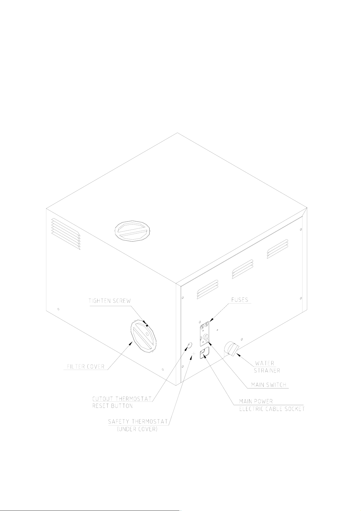
REAR VIEW
14
Page 16
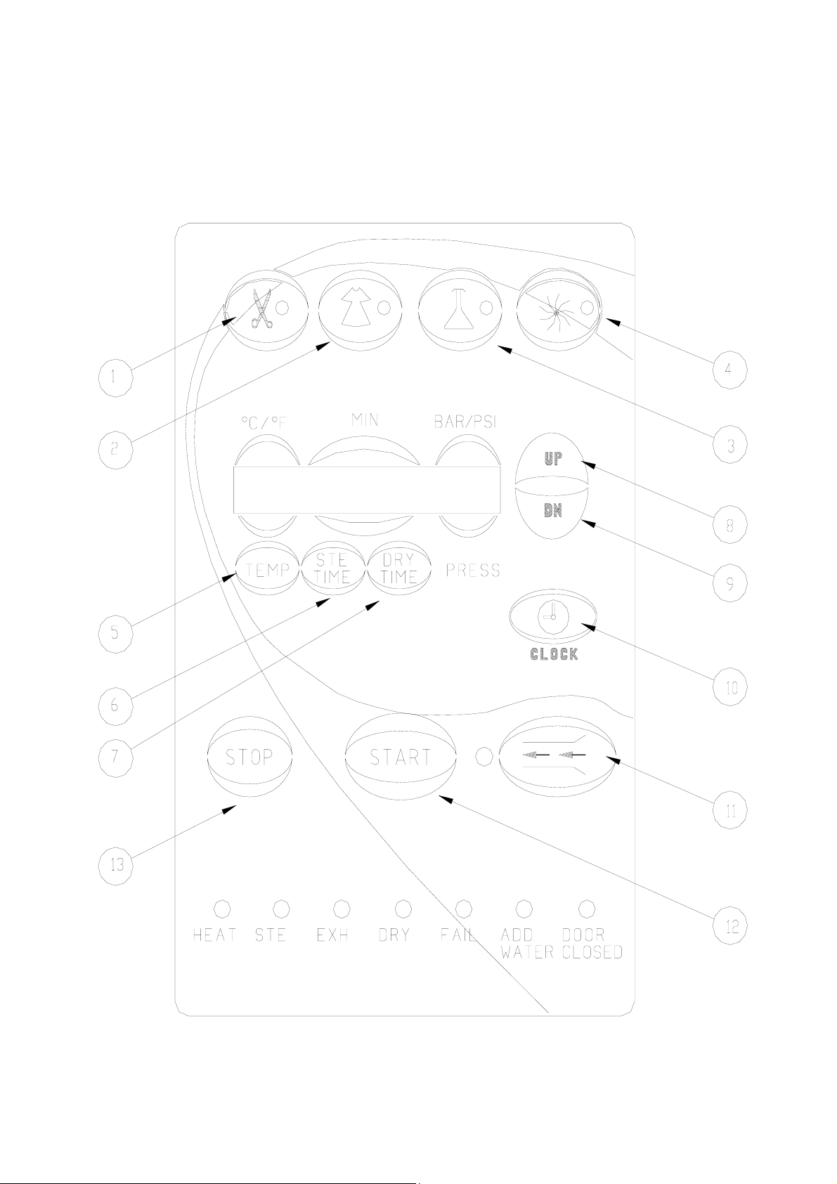
3. KEYBOARD (keys and display)
FRONT PANEL KEYBOARD
Note: See section 3.2 for a description of the Keyboard buttons
Note: See section 3.2 for a description of the Keyboard buttons
15
Page 17
3.1 Indicator Light Description
Programs
Indicators
START
HEAT
STE
EXH
DRY
FAIL
ADD WATER
DOOR
CLOSED
Shows the selected program
Shows the system is running a program
The system is currently in the Heating stage
The system is currently in the Sterilization stage.
The system is in the Exhaust stage.
The system is in the Dry stage.
Shows the system has failed as a result of either a
malfunction, or the STOP key was pressed. A
message is displayed on the screen; the reason for
failure.
This indicator lights if there is a lack of water in the
reservoir.
This indicator lights showing the door is in the
closed position.
16
Page 18

3.2 Description and Functions of the Control Panel Keyboard
3.2.1 Program keys
(1) Unwrapped Instruments
(2) Wrapped Instruments
(3) Glassware s (slow exhaust, no drying)
Pressing one of the above program keys determines the
chosen program. The program parameters are displayed and
the program indicator lights.
(4) Dry Only
Pressing this key allows inclusion of the Additional Drying
procedure for a period of time determined by the operator.
Time range is 0-99 minutes.
3.2.2 Other keys
(5) TEMP.
Pressing this key places the marker under the temperature
displayed on the display. To raise or lower the program
sterilization temperature, press UP or DN keys. To store the
new value in the memory, as the nominal setting, complete
the changing of the parameter by pressing TEMP. key again.
The permitted temperature range for proper sterilization is
250ºF-274ºF (121ºC-134ºC).
Note:
In no case should the temperature be set higher than
274ºF (134ºC)
(6) STE. TIME
Pressing this key places the marker under the sterilization
time displayed on the display. To raise or lower the program
sterilization time, press the UP or DN keys. To store the new
value in the memory, as the nominal setting, complete the
changing of the parameter by pressing STE. TIME key again.
Time range is 3-99 minutes.
Note:
It is important to properly coordinate the STE. TIME
with the sterilization temperature.
(7) DRY TIME
Pressing this key places the marker under the drying time
displayed on the display. To raise or lower the program
drying time, press the UP or DN keys. To store the new value
in the memory, as the nominal setting, complete the changing
of the parameter by pressing DRY TIME key again. The time
range is 0-99 minutes. This key does not allow any change of
the dry time for the Glassware program, for which it is
permanently set to 00 minutes.
(8) UP
Pressing this key in combination with TEMP. (5), STE TIME
(6), DRY Time (7) and CLOCK (9) increases these values.
17
Page 19

(9) DN
Pressing these keys in combination with TEMP. (5), STE
TIME (6), DRY Time (7) and CLOCK (9) lowers these
values.
(10) CLOCK
Pressing the CLOCK programming key displays the date,
with the cursor under the day. Pressing the UP or DN keys
changes the date. Pressing the CLOCK key again moves the
cursor to the month, then year and then time (hour, minute,
second). At this point the display shows the currently set date
and time. If no key is pressed during a 10-second interval, the
system exits the clock-programming mode and returns to the
current program display.
(11) Water Inlet
Pressing this key continuously, allows for manual filling of
the chamber with water. Once the key is released the water
pump stops, the fill valve closes and water stops entering the
chamber.
(12) START
Pressing this key starts the sterilization (or DRY ONLY)
process accordingly to the selected program. Water flows
automatically into the chamber, HEAT and STE. stages
commence and the respective LED indicator lights up.
On completion of the sterilization program the Exhaust stage
will automatically begin, at the end of which a Drying stage
(if previously programmed) will initiate. The respective LED
indicators light up indicating which stage is operating. Once
all stages have been completed the final indicator
extinguishes and the screen displays the “Cycle Finished”
message.
The process will not start if;
• The door is not closed and the DOOR CLOSED
indicator is off.
• The “DOOR UNLOCK” message is displayed.
Note:
Due to inherent elasticity of the door gasket, the CLOSE
DOOR indicator may be illuminated green before a
complete seal is made between the door and the chamber.
Therefore, in order to ensure the door is fully sealed,
tighten the door bolt until ‘hand tight’. Do not over
tighten the bolt as this may result in damage to the
gasket. Should the autoclave fail to reach sterilizing
temperature/pressure, always check first the door is fully
sealed. If not, tighten the door further, as described
above, until completely sealed.
• There is not enough water in the reservoir, (the red
ADD WATER indicator lights and the “ADD
WATER” message is displayed).
18
Page 20

(13) STOP
This key issues the only command accepted by the system
during the running of a program. Pressing this key for over 1
second causes the program to immediately cease running and
enters the EXHAUST stage, at the end of which the “MAN.
STOP” message will be displayed. This key has no function
when the system is not in operation and its only use is to
manually stop a cycle. In normal working conditions on
completion, the system automatically terminates the cycle,
without use of this key.
The STOP key does not function in EXH stage.
3.3 Description of the Display Panel
The display is comprised of 16 characters in one row and is divided into 4
sections.
The first section to the right, continuously shows the actual pressure
within the chamber. This happens whether the system is running a
program or not (provided the main power switch is turned on).
The three other sections are designated to show the parameters of the
selected program, or operating messages. When the system is running a
sterilization program, the sterilization temperature will be displayed above
the TEMP key. Sterilization time will be displayed above the STE. TIME
key and the drying time for the selected program will be displayed above
the DRY TIME key.
If the program is aborted as a result of parameters exceeding the
controlled limits (high, low pressure or temperature etc.) or a manual
STOP command, a message is displayed on the left side of the screen.
When a message is displayed, pressing any key erases the message and
redisplays the selected program screen.
When the system is running a program, the screen displays the current
temperature within the chamber and the remaining time for sterilization or
drying. The current real pressure inside the chamber is always displayed
on the screen.
3.4 Description of Displayed messages and Safety Measures
Door Unlock Message is displayed and the DOOR CLOSED LED
indicator remains unlit, if the door is improperly closed
when the START button is pressed. If the door accidentally
opens during any stage of the cycle, the same message
appears, the DOOR CLOSED LED indicator will turn off,
and the system reacts as if the STOP key was pressed.
Man. Stop Message will be displayed and the FAIL indicator will light
after the STOP key is pressed for longer than 1 second.
Add Water Message is displayed and the respective red LED indicates
insufficient water in the water RESERVOIR. After water is
added to the reservoir, the START button must be pressed
again in order to start the required sterilization cycle.
Water Inlet During the automatic water fill, the message WATER
INLET is displayed, as information to the operator.
19
Page 21

Low Heat Message is displayed and sterilization does not start if the
autoclave has not reached sterilization temperature after
heating for 50 minutes while in the Wrapped or Unwrapped
programs (80minutes in the Glassware program).
Possible causes:
♦ A clogged Air Jet (see cleaning the Air Jet sec 9.4)
♦ No power to the heating elements
♦ Low line voltage delaying heat up
Low Pres Message is displayed, fail indicator lights, and the program
is aborted if the pressure drops 4 PSI (0.27Bar) below the
required sterilization pressure.
Possible causes:
♦ Insufficient water in the chamber (see Low Water
message)
♦ A damaged heating element
♦ A damaged pressure transducer
High Pres. Message is displayed, fail indicator lights up, and the
program is aborted if the pressure rises 10 PSI (0.6Bar)
above the required sterilization pressure.
Possible causes:
♦ A damaged solid state relay
♦ A damaged heating element
Low Temp. Message is displayed, fail indicator lights and cycle is
aborted, if the temperature drops 2.5°C (4.5°F) below the
required sterilization temperature.
Possible causes:
♦ Insufficient water in the chamber (see Low water
message)
♦ Sterilization time has been set for to long a period
♦ A bad temperature sensor
High Temp. Message is displayed, fail indicator lights and program is
aborted if one of the following occurs:
♦ The temperature rises to 3°C (5°F) above the required
sterilization temperature during the sterilization stage.
♦ This message appears during the HEAT stage, if the
temperature sensor is damaged.
Possible causes:
♦ A damaged solid state relay
♦ A damaged heating element
♦ A damaged temperature sensor
Low Water Message is displayed if during the Water Inlet stage
insufficient water enters the chamber. In units with water
pumps, the pump will try three times to fill the chamber
with water if unsuccessful the cycle is aborted and the
message LOW WATER is displayed.
20
Page 22

Message is displayed if during a normal heat up stage the
system determines that there is insufficient water in the
chamber to complete the cycle. This determination is made
by the combined input of two sensors, the Water Electrode
and the Safety Thermostat. Also if a power failure occurs
during the heat or sterilization stage after the power returns
the system will check the Water Electrode to see if there is
sufficient water in the chamber in order to resume the cycle.
If not the cycle will be aborted, the message LOW WATER
will be displayed, and the Cycle Fail indicator will light.
Possible causes:
♦ A dirty or shorted Water Electrode
♦ A clogged water pump or water pump filter
♦ A clogged water line
♦ Unit is improperly leveled
♦ The Air Outlet Valve is stuck closed
♦ A leaky door gasket, door bellows, solenoid valve, safety
valve, or the air jet is allowing steam to escape at a
higher than normal rate.
♦ A power down has occurred and on power up the water
electrode tip is dry
Power Dn. If a power failure occurred during the running of a cycle,
when power resumes a POWER DN message is displayed
for several seconds, if a printer is installed it will print
POWER DN. In addition the system automatically attempts
to complete the STERILIZATION stage if the following
parameters are met:
a. If the temperature drop is less than 4.5°F (2.5°C),
sterilization resumes automatically.
°
b. If the temperature drop is more than 4.5
the cycle fails, POWER DN message is displayed and
printed and LOW TEMP message is displayed.
c. If the pressure drop is more than 4PSI (0.27Bar), the
cycle fails, POWER DN message is displayed and
printed and LOW PRES message is displayed.
If a power failure occurred during the HEAT stage, heating
resumes, provided enough water remains in the chamber. If
not, the cycle is aborted, the message “LOW WATER” is
displayed. If a power failure occurs during the dry and
exhaust stages, the unit will automatically resume operation
once the power is back on.
If a power failure occurs during the GLASSWARE
PROGRAM, the system does not allow fast exhaust (as the
exhaust valve is normally closed) during a power failure or
when power resumes.
CYC Finish When the cycle has been completed successfully the
message CYC FINISH is displayed.
F (2.5°C),
21
Page 23

p
4. STERILIZATION PROGRAMS
The autoclave offers 3 sterilization programs, at temperatures of up to 274°F
(134°C), with or without a drying stage and 1 accessory (dry only) program.
A. Three sterilization programs:
1. Unwrapped instruments
2. Wrapped instruments and porous loads.
3. Glassware
B. Accessory program:
4. Dry only
Note: The nominal data of the program (default settings) can be changed to fit the
needs or a particular office. This is done by means of the TEMP, STE.TIME,
DRY TIME, keys in combination with the UP or DN keys, as described in sec
3.2.2.
4.1 PROGRAM 1. Unwrapped Instruments
For unwrapped instruments and materials, when the manufacturer
recommends autoclaving at temperatures between 250°F and 274°F
(121°C and 134°C) no preset drying stage required.
Nominal parameters default settings
♦ Sterilization temperature: 273°F (134°C)
♦ Sterilization time: 4 minutes.
♦ Dry time: none
Operations Sequence
♦ Heating by actuation of electrical heaters until the sterilization
temperature is reached.
♦ Sterilization temperature is maintained constant for the preset
sterilization time.
♦ Fast exhaust, steam is exhausted out of the chamber at a fast rate until
pressure drops to zero.
Note:
The sterility of instruments processed in unwrapped cycles cannot be
maintained if exposed to non-sterile environment.
PRESSURE (kpa)
TEMPERATURE
Ambient Pressure
and Tem
erature
TIME
t1 t2 t3
= Pressure
= Temperature
t1 = steam generation stage
t2 = Sterilization stage
t3 = Fast exhaust Stage
22
Page 24

4.2 PROGRAM 2 . Wrapped Instruments and Porous
Loads
For wrapped instruments and materials, when the manufacturer
recommends autoclaving at temperatures between 250°F and 274°F
(121°C and 134°C) with a drying stage.
Nominal parameters default settings
♦ Sterilization temperature: 273°F (134°C)
♦ Sterilization time: 8 minutes
♦ Dry time: 30 minutes.
Operations sequence:
♦ Heating by actuation of electrical heaters until the sterilization
temperature is reached.
♦ Sterilization temperature is maintained constant for the preset
sterilization time.
♦ Fast exhaust, steam is exhausted out of the chamber at a fast rate until
pressure drops to 4 psi abs. (124 kPa abs.).
Ambient Pressure
and Temperature
= Pressure
♦ Dry heating and forced air circulation for 30 minutes to remove
leftover moisture from the instruments and wraps,
PRESSURE (kpa)
TEMPERATURE
t1 t2
= Temperature
t3
t1 = Steam generation stage
t2 = Sterilization stage
t3 = Fast exhaust Stage
23
Page 25

4.3 PROGRAM 3: Glassware
For all glassware intended for sterilization.
Nominal parameters default settings
♦ Sterilization temperature: 250°F (121°C).
♦ Sterilization time: 30 minutes.
♦ Slow exhaust: 15 to 20 minutes.
♦ Drying time: drying is not allowed.
Operations sequence:
♦ Heating by actuation of electrical heaters until the sterilization
temperature is reached.
♦ Sterilization temperature is maintained constant for the preset
sterilization time.
♦ Slow exhaust, heating is stopped and steam is let out of the chamber at
a slow rate until the temperature decreases to 185°F (85°C).
♦ No drying is allowed
Ambient Pressure
and Temperature
= Pressure
4.4 PROGRAM 4: Accessory (Dry Only)
The purpose of the accessory drying program is to offer an alternative
PRESSURE (kpa)
TEMPERATURE
t1 t2 t3
t1 = Steam generation stage
t2 = Sterilization stage
= Temperature
t3 = Slow exhaust Stage
in situations where the dry time in the wrapped or unwrapped cycle is
insufficient. Rather then wait for the items to air dry or run another
complete cycle with a longer dry time, just select the accessory drying
program to continue the heat assisted drying process.
TIME
24
Page 26

5. PRINTER (Optional)
The printer is an optional device. If the autoclave is not equipped with a
printer paragraph 5 is not applicable.
5.1 Printer Operation
The autoclave is equipped with a character printer, which prints a
detailed history of each cycle performed by the instrument (for the
record or for subsequent consideration).
The printing is made on thermal paper with 24 characters per line and
contains the following information:
♦ Software version
♦ Date and time of cycle start
♦ Selected program and parameters
♦ Sterilization pressure
♦ Sterilization temperature
♦ Sterilization time
♦ Cycle identification.
When the sterilization cycle begins the printer starts printing the above
data.
After the preliminary printing, the autoclave starts performing the
sequence of operations of the cycle. The measured values of
temperature and pressure are printed at fixed time intervals, according
to the phase of the process, as shown in the table below.
The data is printed from the bottom up, beginning with the program
name and ending with “O.K.” for a complete cycle or “FAIL” for an
aborted cycle.
For an example of a typical printout, see next page.
25
Page 27

PRINTER OUTPUT DESCRIPTION
Autoclave No:01 Number of the autoclave with respect to other units in the
same location
Load number: 0005 Load number. Useful to determine when to clean the
chamber. (upon reaching 255 this number is reset to 0)
Operator :___________ To be filled in manually by operator.
O.K. Cycle completed successfully
−−−−−−−−−−−−−−−−−−−
D20 220°F 00P The time, temperature and pressure during drying.
----------------------E20 251°F 02P The time, temperature and pressure during exhaust.
-----------------------
S20 273°F 31P The time, temperature and pressure during sterilization.
*
* Prints sterilization data every 1 minute.
*
S13 273°F 31P The time, temperature and pressure during sterilization.
S12 273°F 31P The time, temperature and pressure during sterilization.
---------------------H08 231°F 10P The time, temperature and pressure during heating.
H04 137°F 00P The time, temperature and pressure during heating.
*
* Prints heat up data every 4 minute.
*
H00 72°F 00P The time, temperature and pressure during heating.
----------------------
MN TEMP PRES
DRY: 30min Drying time for selected program.
TIME: 08min Sterilization time for selected program.
TEMP: 273°F Sterilization temperature for selected program.
PROG: PKG Selected program: Unwrapped instruments
TIME: 15:12:06 Time sterilization cycle begun.
DATE: 07:31:00 Date sterilization cycle begun.
Version:
T01EAWP Number and version of the program
Legend
MN Time elapsed in minutes
H Heating stage
S Sterilization stage
E Exhaust stage
D Drying stage
P psi
26
Page 28

5.2 Printer Handling
The printer is driven and controlled automatically by the control unit,
while the autoclave performs a sterilization program.
Figure 1 Figure 2
To set the paper roll in the printer perform the following steps:
5.2.1 Gently push the clips for removing the front panel, remove the
panel and pull out the printer gently.
5.2.2 Set the paper roll on the shaft (See Figure 1). Since the outer and
inner surfaces of the paper are different set the roll so that the
printing surface is the outer.
5.2.3 Gently push the paper face down into insertion opening (A) in
Figure 2. Keep pressing the feed switch (B) until the paper comes
out from the print head (C).
5.2.4 When the paper emerges from the print head, insert it in the paper
cutter (the slot in the front panel) and reassemble the front panel
on the unit.
The paper roll is set inside the unit and the printer is ready for use.
NOTE: If the paper is not pulled in by the rollers even when you press
the feed switch (B) push the paper in.
5.2.5 To ensure a reliable operation of the printer perform the
following:
5.2.5.1 Turn the main switch to the OFF position.
5.2.5.2 Press the feed switch and at the same time turn the
main switch to the ON position. Verify that the
printer performs an operation test by printing all the
built-in characters
The following precautions have to be taken ensuring the proper
operation of the printer:
♦ Avoid contact between the paper and the hot parts of the
autoclave, as the paper will be blackened.
♦ Do not pull out the paper roll from the paper insertion opening.
♦ Use only the 58mm. wide thermal paper rolls, supplied by your
dealer. Larger rolls will not fit inside the printer.
27
Page 29

6. INSTALLATION INSTRUCTIONS
Caution:
The sterilizer must be placed on a rigid and leveled surface. The stand must
be able to hold the load of the device and loaded material.
Note:
Make sure while placing the autoclave, to leave space around the machine,
to give the technician access to service the machine.
6.1 Electrical
The electrical connection should comply with the devices power
requirement. It must also comply with local installation and safety rules
and regulations. The voltage supplied to the device must comply with
the label ± 5%.
In order to avoid any injury by electrical hazard, it is mandatory for the
customer to have installed an earth leakage relay (GFI outlet or circuit
breaker) in the electrical circuit to which the autoclave is connected.
This relay disconnects all the poles of the electrical power line in case
of accidental contact with the autoclave’s metal enclosure, by the
operator or another person, leading to a dangerous leakage current.
Note: Keep the back and the right side of the autoclave approximately 1”
(25mm) away from the wall to allow for ventilation.
Connect the power cord to the socket on the rear side of the autoclave;
plug it into the supply outlet. The autoclave must be connected to a
properly grounded outlet.
6.1.1 Setup
Your new Tuttnauer Autoclave was set at the factory and
requires a minimal of setup.
♦ Make sure the counter is level and sturdy
♦ Make sure all the feet are on the autoclave and none have
been lost.
♦ Position the autoclave on the counter
♦ Fill the reservoir with distilled water (see sec 6.5)
♦ The unit is ready to operate
28
Page 30

6.2 Water Filling
6.2.1 Automatic Water Filling
The proper amount of water for automatic filling in your new
Tuttnauer autoclave has been preset at the factory. However, if
in routine operation, there is inadequate water in the chamber,
the operator can adjust the level with the automatic built-in
system by doing the following.
1. Press STOP key repeatedly until the message “code xxx”
appears on the display.
2. Use the UP or DN arrow keys to change the code to 105, then
press the STOP key
3. A message will be displayed saying “Water in = xx sec”
4. Press UP or DN keys to increase or decrease water inlet time.
5. Press the STOP key to enter new water inlet time into
memory.
6. If necessary press the STOP key again to bring up the
program display.
Note:
DO NOT attempt to automatically fill the chamber with the DOOR
open. Water will over flow out of the chamber.
Warning:
If it becomes necessary to RESET the software program it will be
essential to repeat all steps listed above. This will ensure that the
correct amount of water enters the chamber for operation.
6.2.2 Checking the automatic fill
To check the automatic fill, follow these steps:
1. Remove any water that is in the chamber.
2. Make sure the unit is turned on.
3. Place a collecting vessel under the autoclave's door.
4. With the door open, press and hold the door switch, then
press the START key.
5. When water starts flowing into the chamber release the door
switch.
6. Water should come beyond the groove at the front of the
chamber, and a small amount will pour into the collecting
vessel.
7. After the automatic filling is completed, tilt the autoclave and
pour all the water in the chamber into the collecting vessel.
8. Measure and verify that the amount of water pumped into the
chamber is 500-600 ml.
9. If the water is not filling correctly then follow the adjustment
procedure above.
29
Page 31

Warning:
If it becomes necessary to RESET the software program it will
be essential to repeat all steps listed above. This will ensure that
the correct amount of water enters the chamber for operation.
VERY IMPORTANT – Due to the fact that the water lines are
empty when the unit is shipped air may become trapped in the
lines. It is recommended that for the first operation these steps
are followed to make sure water is flowing freely.
Open the door, press the Water Inlet key. When water enters the
6.3 Lifting and carrying
chamber release the key and remove the water.
Caution:
Before moving the autoclave, Make sure that the electric cord is
disconnected from the power and there is no pressure in the chamber.
1. Disconnect the power supply cord.
2. Drain the water from the reservoir and vessel.
To avoid injuries, lifting and carrying should be done by two people.
Do not drop this device!
6.4 Loading and unloading the Device
6.4.1 Safety
Protective equipment and clothes and other safety instructions
should be implemented in accordance with local and national
regulations and/or rules!
For proper sterilization - Do not overload the chamber. Only
autoclavable products shall be used; please refer to the materials
or instruments manufacturers instructions for sterilization of
unknown materials or instruments.
6.4.2 Loading
Correct loading of the autoclave is essential to successful
sterilizing for several reasons. Efficient air removal from the
chamber and the load will permit steam penetration and
saturation, and allow proper drainage of condensate. Additionally,
correct loading will reduce damage to packs and their contents
and maximize efficient use of the sterilizer.
For detailed loading instructions, see sec. 7 (Preparation before
sterilization)
6.4.3 Unloading
On completion of the cycle, the load shall be immediately
removed from the sterilizer and a visual inspection made to
ascertain that the load is dry, and that sterilizing indicators have
made the required color change.
30
Page 32

6.5 Filling the Water Reservoir
Remove the water reservoir cover. Pour distilled water into the
reservoir through the opening on top of the autoclave until it reaches
the base of the safety valve holder, approximately 0.7 gallons (3 liters).
Use water-having characteristics as per table in sec 2.11
Caution:
Under no circumstance should water be filled above the safety
valve holder.
Exit for steam spray
USE DISTILLED WATER ONLY. The impurities in tap water will
create the need for more frequent cleaning and maintenance, in
addition they will accumulate and block the hole of the Air Jet. This
will prevent the temperature in the chamber from rising properly. This
will cause the unit to abort its cycle, spore tests to fail and indicator
strips not to change color. It is essential from time to time during
heating and sterilization phases that a spray of steam should escape,
from the Air Jet, causing a hissing sound. If no escaping steam is
evident or no hissing sound heard then follow the instructions in sec
9.4 for cleaning the Air Jet.
31
Page 33

7. PREPARATION BEFORE STERILIZATION
The purpose of packaging and wrapping items for sterilization is to provide an
effective barrier against contamination during storage, once the items have
been sterilized.
Instruments to be sterilized must be free from all residual matter, such as
blood or organic tissue. Instruments must also be dry and free from mineral
deposits. Such substances may cause damage to the instruments themselves or
the Sterilizer.
1. Clean instruments immediately after use to remove any residue. It is
recommended that all instruments be ultrasonically cleaned using
Tuttnauer's CLEAN AND SIMPLE enzymatic cleaning tablets or other
suitable solution.
2. After cleaning, rinse instruments under tap water for 30 seconds and pat
or air dry to remove residual minerals. If your tap water has a high
mineral content then rinse a second time in a bath of distilled water to
remove minerals.
3. Launder textile wraps prior to reuse, but do not use bleach.
4. Follow the instrument manufacturer’s instructions on the use of products
for cleaning and lubricating instruments that have been ultrasonically
cleaned.
5. Be sure that instruments of dissimilar metals (stainless steel, carbon steel,
etc.) are separated. Carbon steel instruments should be bagged or placed
on autoclavable towels and not directly on stainless steel trays (mixing
will result in the oxidation of these metals).
6. Do not place materials to be sterilized against the chamber’s wall. Place
the material only on the tray or rack.
7. When using a paper / plastic bag the plastic side should always be down.
8. Check the instructions of the item manufacturer as to the proper procedure
for sterilizing each item.
9. Items must be sterilized in an open position. Surfaces that are hidden
because the item is in a closed position will not be exposed to the steam
and will not be sterilized
10. Place a sterilization indicator in each tray or inside each wrapped pack.
11. At least once a week use a biological spore test (Bacillus
Stearothermophilus) in any load to insure proper sterilization. (Be aware
testing standards may vary) Always follow the spore test manufacturer’s
instructions
12. Make sure that all instruments remain apart during the sterilization cycle.
Surfaces that are hidden because items are covering other items will not
be exposed to the steam and will not be sterilized
32
Page 34

13. Verify that packaging methods are in accordance with the good practice
approach and the packaging materials used are in agreement with
applicable standards
14. Empty canisters should be placed upside-down in order to prevent the
accumulation of water.
15. Do not overload the Sterilizer trays. Overloading will cause inadequate
sterilization & drying.
16. Allow a distance of approximately 1" between trays to permit steam
circulation.
17. Wrapped instruments should be placed in material which will allow steam
penetration and promote drying, such as autoclave bag, autoclave paper,
or muslin towels.
18. Do not stack pouches. It is recommended that a pouch rack such as the
Tuttnauer POUCH RACK be used to insure proper steam penetration and
adequate drying. Surfaces that are hidden because the items are being
stacked will not be exposed to the steam and will not be sterilized
For models 2340, 2540 For model 3870
19. Tubing should be rinsed after cleaning. When placed in the tray make sure
that both ends of the tubing are open and there are no sharp bends or
twists
20. Packs should be placed upright on the tray. They should not be touching
each other or the Chamber walls. There should be about 1” between packs
for proper steam circulation.
33
Page 35

21. Glassware
Use only heat-proof glass. Verify that the beaker is only filled 2/3 full and
the lid is on loosely to allow for expansion.
22. If spotting is detected on the instruments the first step would be to use an
ordinary eraser to remove the spot. If there is no pitting under the spot
then the spot was only dirt. Dirt spots on an instrument may be an
indication that the autoclave needs to be cleaned or that the instruments
were not adequately cleaned or dried. If removal of the spot reveals pitting
then the spot was most likely rust. Rust spots on an instrument are not
uncommon on inexpensive instruments. It may also be an indication that
the instruments were rinsed in tap water with a high content of minerals.
These minerals when exposed to high temperature and steam will
accelerate the oxidation of the metal. One suggestion would be to final
rinse the instruments in a distilled water bath.
23. If the instruments exhibit a discoloration this can be due to the mixing of
carbon steel and stainless steel. When these two metals come into contact
with each other an electrolysis occurs that breaks down the metal. The
best solution is to separately wrap the carbon steel to insulate it from other
instruments or the trays.
24. Items should not be allowed to touch the walls of the Chamber as the hot
metal can damage the item.
34
Page 36

8. OPERATING INSTRUCTIONS
It is important to clean the hole of the air jet, as described in sec. 9.3
before starting operation of the autoclave, for the first time.
1. Remove water reservoir cover. Pour distilled water into the reservoir, through
the opening on top of the autoclave, until it reaches the base of the safety
valve holder, approximately 0.7 gallons (3 liters).
2. Plug the power cord into the back of the autoclave and into the wall outlet.
3. Turn on the rocker switch mounted on the bottom of the front panel.
4. If a printer is installed then set the clock with the proper date and time.
5. Press the required key to select the required program .The light indicator of
the selected program is illuminated; indicating the program has been selected.
The preset data of the program, sterilization temperature, time and dry time
are displayed.
6. Load the material to be sterilized into the chamber according to instructions
in sec. 7 (Preparation Before Sterilization) and close the door making sure the
‘Close Door’ indicator is illuminated.
NOTE:
Due to the inherent elasticity of the door gasket, the CLOSE DOOR
indicator light may be illuminated green before a complete seal is made
between the door and the chamber.
Therefore, in order to ensure that the door is fully sealed, when the green
light has been illuminated continue to tighten the door bolt until “hand
tight”. Do not over - tighten the bolt as this may result in damage to the
gasket.
Should the autoclave fail to reach the sterilizing temperature/pressure,
always check first that the door is fully sealed. If not, then tighten the
door bolt further, as described above, until completely sealed.
7. Press the START key to put the autoclave in operation.
WATER INLET is displayed until the correct volume of water is
automatically introduced.
The autoclave starts performing the sequence of operations. The actual
measured values of pressure and temperature are displayed continuously (and
printed with optional printer).
The indicator lights HEAT, STE, EXH and DRY are turned on and off as
each stage is started and completed.
NOTE:
It is possible to change parameters, only when the autoclave is not in
operation. In order to change the fixed preset parameters, proceed as
follows:
To increase or decrease the sterilization temperature, sterilization time
or dry time, follow instructions from sec. 3.2.2.
Pressing the UP/DN key, advances the setting upward or downward by
one unit. The displays are updated with every change in the preset data.
8. During any program that has a drying stage scheduled, the dry stage begins
after the steam exhaust stage. The autoclave is equipped with an air
compressor that during the drying stage, draws air through a HEPA filter
(0.2µm), and pushes that air through the heated chamber and out the air outlet
valve to remove moisture and facilitate the drying operation. Drying is
performed with the door closed.
35
Page 37

9. At the end of the cycle a buzzer rings for approximately 5 seconds, the
START light switches OFF. The air outlet valve is opened to prevent
formation of a vacuum.
In the event of a program failure, the exhaust valve is opened to release
pressure from the chamber and a continuous buzz will sound for 5 seconds
followed by an interrupted buzz of 7 seconds.
10. Open the door and unload the sterilized material from chamber.
11. The sterility of instruments processed in unwrapped cycles cannot be
maintained if exposed to non-sterile environment.
Note:
A minimum time interval of 10 minutes needs to be observed between the
end of a cycle and the start of a new cycle, to prevent overheating of the
autoclave.
Do not touch the strainer’s cover, mounted on the exhaust line, during
and shortly after operation, it will get very hot.
Touching the hot strainer’s cover may cause severe injuries.
36
Page 38

MAINTENANCE INSTRUCTIONS
37
Page 39

9. MAINTENANCE INSTRUCTIONS
9.1 Preventive and Scheduled Maintenance
The maintenance operations described in this chapter need to be
followed as indicated to keep the device in good working condition.
The instructions that follow can easily be carried out by the office
personnel and do not require a service technician.
Should the need arise technical assistance or a serve technician can be
requested by either calling your dealer or Tuttnauer USA..
9.1.1 Daily
1. Clean door gasket with a mild detergent, water and a soft
cloth or sponge. The gasket should be clean and smooth.
9.1.2 Weekly
1. ONCE PER WEEK, clean the air jet. To ensure that the
temperature inside the chamber rises properly it is necessary
to keep the air jet clean. A dirty air jet will prevent indicator
strips from changing color and cause spore tests to fail. See
sec. 9.4.
2. Clean the water sensor in the rear of the chamber with a
damp cloth or sponge. Cleaning the dirt off the sides of the
sensor is more important that the tip (see sec 9.10).
3. Once per week clean and descale the chamber, copper tubes
and the reservoir using Chamber Brite (see sec. 9.9).
4. Take out the tray holder and trays. Clean the tray holder and
trays with detergent or a non-abrasive stainless steel cleaner
and water, using a cloth or sponge. Rinse the tray holder and
trays immediately with water to avoid staining the metal.
Caution
Do not use steel wool, steel brush or bleach as this can
damage the chamber and trays!
5. Put a few drops of oil on the 2 door pins and door tightening
bolt.
6. Clean the outer parts of the autoclave with a soft cloth
9.1.3 Periodically
1. Once every month clean and check the safety valve.
2. Replace the air filter, every 6 months, or as needed (see sec.
9.2).
3. Replace the door gasket every 12 months, or as needed (see
sec. 9.5).
4. Once every six months clean the fan grid with compressed air
from the inside outward.
5. Clean strainer once a month as per sec. 9.8. Cleaning
frequency may be reduced according to previous
maintenance.
6. Once a year inspect the locking device for excessive wear.
38
Page 40

9.2 Replacing the Air Filter
To facilitate drying the instruments with the door of the chamber
closed, the autoclave is equipped with an air compressor and HEPA
filter (0.2µm). During the drying stage the compressor draws air
through the HEPA filter and forces the circulation of that air through
the heated chamber to remove moisture from the wrapped instruments.
The filtration of the air is performed by the bacteriological filter and
depending on the usage of the autoclave and the surrounding
environment that will determine the frequency of replacement.
The filter is mounted in an opening on the right sidewall of the
autoclave enclosure, this is to allow easy access for replacing it. (see
picture below)
To replace the filter proceed as follows:
1. Remove the securing screws and then the filter cover by turning the
cover counter-clockwise until the handle is at a vertical position.
2. Pull out the cover with the filter attached.
3. Disconnect the flexible tube from the filter
4. Replace the filter with a new one connecting it to the flexible tubing.
5. Reassemble the cover and lock it into position by turning it a ¼ turn.
6. Fasten the securing screws.
39
Page 41

9.3 Draining the Reservoir
Caution
Before starting, ensure that the electric cord is disconnected and
there is no pressure in the autoclave.
The drain valve is located on the front left side of the autoclave after
the door is opened. The function of the drain valve is to drain the water
reservoir.
1. Connect the silicone hose, supplied with the autoclave, to drain into a
bucket.
2. Turn drain valve counter clockwise to the open position.
3. Fully drain the reservoir
4. With a quart of tap water flush out the reservoir
5. Turn drain valve clockwise to the close position.
6. Connect the electric cord to power source.
7. Fill the reservoir with distilled water to just below the safety valve
(see sec 6.5)
8. Turn on the main power switch.
9. The autoclave is now ready for use.
40
Page 42

9.4 Cleaning Air Jet
(Located in the water reservoir.)
A dirty air jet is the number one cause of failed spore tests
The elimination of air from the sterilization chamber during heat up is
critical to the proper operation of the autoclave. Failure of the air
removal system will be responsible for incomplete sterilization,
indicator strips that do not turn, failed spore tests and aborted
sterilization cycles. A clogged air jet will result in receiving the error
message “Low Heat”.
The air jet consists of a small orifice with a clean out wire inserted in it
(wire is permanently installed and will not come out). It is required that
the air jet be cleaned once per week or more often if necessary, to
remove any accumulated dirt and debris.
It is preferred to clean the air jet when the unit is running a cycle and
under pressure. This is so that any loosened debris will be blown away,
however, it can be done while the unit is idle.
1. Remove the water reservoir cover.
2. Clean the hole of the jet by manipulating the air trap wire back and
forth 10 times
It is important to clean the hole of the air trap, as described at point 2
before starting operation of the autoclave, for the first time.
41
Page 43

9.5 Replacing the Door Gasket
Pull off the gasket from the door groove. Install the new gasket as
described in drawings 1, 2 and 3 above.
Caution!
This gasket is designed with a trapezoidal cross section. The gasket
should be placed with the widest side towards the door.
42
Page 44

9.6 Checking the Safety Valve
(Located in the water reservoir)
In order to prevent the safety valve from becoming blocked, it is
necessary to allow the steam pressure to escape through the valve. This
procedure should be done every month as follows:
1. Operate the sterilization cycle according to the manual.
2. Allow a pressure of approximately 30 psi (260 kpa ) to build up in
the chamber.
3. Turn the unit off
4. Remove water reservoir cover
Caution!
This next step will expose you to HOT STEAM
Caution!
To avoid being burned, by hot steam, do not place your face over
the safety valve.
5. Pull the ring of the safety valve using a tool, i.e. screwdriver, hook
etc and open the safety valve for 2 seconds then release. Be careful
not to burn your hands.
6. Turn the unit back on and press the STOP key to abort and vent
the cycle.
7. Wait until pressure decreases to zero, only then can the door be
opened.
43
Page 45

9.7 Replacing the Fuse
Caution
Make sure that the electrical power cord is disconnected!
Use a screwdriver to unlock the fuse holder cover by turning it counter
clockwise ¼ turn, and pull it out.
Insert a new fuse into the holder and turn the cover clockwise until
locked.
Make sure that the correct fuse is installed
1. Water Pump Fuse: 1.25 amps
2. Air Pump Fuse: 2.0 amps for 120V
1.25 amps for 230V
44
Page 46

9.8 Cleaning water outlet strainer
Caution!
Before proceeding, Make sure that the electric cord is disconnected
and there is no pressure or water in the chamber.
Warnings
1. The strainer’s cover is HOT
Do not touch the strainer’s cap, mounted on the exhaust line,
during and shortly after operation. Touching the hot strainer’s
cap may cause severe injuries.
2. If maintenance operation is performed while strainer cap is hot,
use heat resistant gloves to avoid injuries.
1. Open the strainer cap.
2. Remove the strainer element.
3. Rinse the strainer with water, using a brush if necessary.
4. Reinstall the strainer element.
5. Close the strainer cap.
Cap
Gasket
45
Strainer
element
Strainer
Housing
Page 47

9.9 Cleaning Table Top Autoclaves with Chamber Brite ™
CHAMBER BRITE ™ is a cleaning and descaling agent designed
specifically for the cleaning and removal of water deposits, oxides and
other sediments that are found in steam sterilizers. The material is a
combination of acidic salts and additional cleaning materials. Chamber
Brite ™ autoclave cleaner has been formulated specifically to be a fast,
powerful and easy to use cleaner for steam sterilizers.
If the autoclave is not cleaned regularly dirt and debris will build up and
clog the tubing and solenoid valves. This dirt can also be transmitted to
the instruments during sterilization. In addition a layer of dirt on the
stainless steel chamber traps moisture against the metal and will lead to
the chamber becoming porous and failing.
It is recommended that your autoclave be cleaned with CHAMBER
BRITE ™ once per week
Caution!
NEVER
use bleach, steel wool, a steel
brush or anything abrasive to scrub or
clean the Chamber
Cleaning Procedure
1. Important – all steps in this procedure
must
be completed without
interruption.
2. When the autoclave chamber is cold,
remove instruments and trays from
the autoclave.
3. Open the door and spread the
contents of a packet in a straight even
line along the bottom of the chamber,
from back to front.
4 Select and start program No. 1.
(without dry
) When the cycle is
finished it will automatically exhaust
5. At the end of the exhaust cycle drain
the water from the reservoir.
6. Fill the water reservoir with distilled
water.
7. Repeat a sterilization cycle without
Chamber Brite ™ powder, to remove
any excessive dirt in the pipes. Select
and start program No. 1. (without
dry) When the cycle is finished it
will automatically exhaust
8. At the end of the exhaust cycle drain
the water from the reservoir.
9. Turn the autoclave off and allow chamber to cool.
46
Page 48

10. Remove the tray holder; rinse and wipe the interior of the chamber
with a damp cloth.
11. Fill the reservoir with distilled water or mineral free water only.
12. Press the manual water fill button and allow a small amount of water
(2-4 ounces) to fill chamber and flush out the fill tube. Remove
water from chamber.
13. The instrument is ready to use.
IMPORTANT:
DO NOT sterilize instruments during the cleaning process!!!
CAUTION:
Keep out of reach of children. Contains mildly acidic
ingredients. Avoid contact with the skin, eyes or clothing. Wash
hands well after touching the powder, in the case of eye contact
flush with continuous running water for at least 15 minutes. If
irritation persists get medical attention. If accidentally
swallowed, do not induce vomiting, drink large amounts of
water and obtain medical attention. MSDS available upon
request.
Use one packet of CHAMBER BRITE ™.
Clean every 20 cycles or as needed.
47
Page 49

9.10 Water Sensor Cleaning
It is required that the water sensor be cleaned at least once per
week. Cleaning the sensor will ensure that the water level in the
chamber is properly reported to the microprocessor all during the
cycle.
The water sensor is located in the rear of the chamber. It is easily
cleaned using a damp cloth or sponge, you may use a mild soapy
solution if you like. It is important to wipe the sides of the sensor
as well as the tip, to remove any dirt or debris that may have built
up.
48
Page 50

Solution
1.1 Make sure the main switch is in the ‘On’ position.
(see front view drawing at the front of this manual)
1.2 Make sure the power cord is properly connected to the machine and the mains.
(see rear view drawing at the front of this manual)
1.3 Check the reset button on the cut-out thermostat. (see rear view drawing at the
front of this manual)
1.4 Make sure the circuit breaker has not tripped. Lift the circuit breaker lever.
2.1 Check the air trap (inside the water reservoir).
(see sec. 9.3 Air Trap Cleaning Procedure)
2.2 Make sure the machine has the proper amount of sterilization load.
3.1 Clean the water level electrode inside the vessel. (see sec 9.10)
3.2 Check that the door is fully closed, the door gasket is seated and there is no
steam leakage. replace the door gasket if necessary.
(see sec. 9.5 Replacing the Door Gasket)
3.3 Check the leveling of the machine.
(see sec. 6, Installation).
4.1 Clean the water level electrode inside the vessel. (see sec 9.10)
4.2 Check that the door is fully closed, the door gasket is seated and there is no
steam leakage. replace the door gasket if necessary.
(see sec. 9.5 Replacing the Door Gasket)
4.3 Check the leveling of the machine.
(see sec. 6, Installation).
Problem
This troubleshooting chart enables the user to solve minor malfunctions, prior to requesting service.
Only technical personnel having proper qualifications and holding technical documentation (including a technician manual) and
10. TROUBLESHOOTING FOR THE OPERATOR
adequate information are authorized to service the apparatus.
1. The machine is not responding
2. ‘Low Heat’ is displayed
3. ‘Low Water’ is displayed
4. ‘Low Pres’ is displayed
49
Page 51

Solution
5.1 See Low Water problem above
5.2 The sterilization time has been set for too long of a period, allowing the chamber
to run dry
6.1 If this message is displayed during heat up it indicates a bad temperature sensor
6.2 Heating elements are remaining on instead of cycling on and off.
In both cases call for a technician.
Problem
5. ‘Low Temp’ is displayed
6. ‘High Temp’ is displayed
7.1 Air jet is clogged. Clean air jet according to sec. 9.4.
7.2 Heating elements are remaining on instead of cycling on and off. Call for a
technician.
7.3 temperature sensor (PT100) is faulty or dirty. Call a technician.
7. ‘High Pres’ is displayed
8.1 Make sure the paper is mounted in the right way. Only one side of the paper is
printable.
(see sec. 5.2, Printer handling)
9.1 Make sure the paper is inserted in the printer.
(see sec. 5.2, Printer handling)
9.2 Switch off the machine and switch it back on while pressing the feed button on
the printer. If the printer prints a test printout, the printer is O.K. and there is a
problem with the electronics. Contact your dealer to solve the problem.
If the printer does not print the test printout, there is a problem with the printer.
Contact your dealer to solve the problem.
10.1 Make sure the ‘feed button’ on the printer is not stuck.
the machine is switched
printed on the paper.
8. The printer prints, but nothing is
9. The printer does not print.
with a
printer
If equipped
on, the printer gives paper feeds
all the time.
10. When
50
Page 52

Solution
Problem
11.1 Make sure the door is tightened enough and the door gasket is sealing the
Chamber. Replace the door gasket. (see sec. 9.5 Replacing the Door Gasket)
12.1 If you are running a ‘glassware’ program this is normal. The slow exhaust will take
from between 15 and 20 minutes. (see, PROGRAM 3 sec 4.3)
13.1 Clean strainer according to instructions. (see sec 9.8)
takes a very long time.
11. The machine is leaking at the door
12. When running a cycle, the exhaust stage
13. Water does not exit chamber due to
14.1 Open drain by turning counterclockwise. Place a heavy object over the reservoir
cover. Blow compressed air into the drain, this should force any debris back into
the reservoir. Clean out the reservoir.
14.2 Disassemble the drain valve by turning counterclockwise past the stop point.
Remove the valve and clean, blow out the line as needed (see 14.1). Reassemble
the valve by turning clockwise, make sure to press the large “O” ring into the
groove on the autoclave.
15.1 Clean the air jet as per sec 9.4.
15.2 Make sure the sterilization time and temperature are set correctly, if in doubt use
the default settings.
15.3 Make sure the autoclave is not to heavily loaded. See sec 7.
16.1 Drying cycle may be too short. (see sec 4)
16.2 Autoclave may be overloaded. (see sec 7)
16.3 The chamber strainer may be clogged (see sec 9.8)
16.4 The HEPA filter may be clogged (see sec 9.2)
clogged outlet strainer.
14. The drain is clogged
are not turning
15 Spore test are failing or indicator strips
16. Wrapped items come out wet
51
17.1 Water sensor may be dirty (see sec 9.10)
17.2 Wall outlet voltage may be to high
17.3 Items may be touching the walls or bottom of the chamber. Load autoclave
according to instructions in sec 7 (Preparation Before Sterilization).
17. Wraps come out burned
Page 53

Solution
18.1 First to determine true rust, use a pencil eraser to remove the brown spot. If there
is no pitting then the instrument is just dirty (see sec 7 Preparation before
sterilizing and sec 9.9 Cleaning the autoclave).
If there is pitting beneath the brown spot then the rusting may be caused by
minerals in the water used for rinsing (see sec 7 Preparation before sterilizing).
18.2 Use only distilled water for sterilizing
18.3 Make sure dissimilar metals (carbon steel, stainless steel, etc) have not come into
contact with each other.
19.1 Press the STOP key for 2 seconds to abort any program that may still be running
20.1 Clean the air jet (see sec 9.4).
20.2 Check for proper voltage at the wall outlet
21.1 Sterilization temperature set to high. Maximum setting 274ºF (134ºC)
22.1 The autoclave may be overloaded (see sec 7 Preparation for Sterilization)
22.2 Replace the HEPA filter (see sec 9.2)
23.1 check water level in reservoir.
23.2 Check for an obstruction at the bottom of the reservoir blocking the pick up tube
23.3 Clean the water sensor (see sec 9.10)
23.4 Try filling the machine manually using the Manual Inlet key (see sec 3)
Problem
18. Instruments are rusting
19 Keyboard does not respond
20. Autoclave takes too long to heat up
21. Loud noise coming from reservoir
52
22. Drying takes too long
23. Chamber not filling
Page 54

Solution
Problem
24.1 Use Chamber Brite ™ to clean the autoclave, very dirty machines may require two
cleanings. (see sec 9.9)
24. Chamber very dirty
25.1 Remove the trays and rack and clean as per instructions in sec 9.1.2
25. Trays and rack very dirty
If the problem persists, contact your dealer or Tuttnauer USA for further assistance.
53
 Loading...