

Tuttnauer EZPlus-Series Service manual

Technician Manual
Electronic Table -Top Autoclaves
Models EZ9Plus & EZ11Plus
Cat. No. MAN205-0443002EN Rev. E
Manufactured by: Tuttnauer Co. Ltd., Har Tuv Industrial zone B P.O.Box 170,
Beit Shemesh 99000, Israel Tel: 972 2 9904611, Fax: 972 2 9904730
Tuttnauer U.S.A. Co, Ltd. 25 Power Drive Hauppauge, NY, 11788, USA.
Tel (631) 737 4850, (800) 624 5836, Fax: (631) 737 0720

http://www.tuttnauerusa.com/

Page 1
TABLE OF CONTENTS
PARAGRAPH PAGE NO.
1 Introduction 4
2 Symbol Description 4
3 Description of the control system. 5
3.1 Block Diagram Hardware Software Components 5
3.2 Application system architecture 5
3.3 Hardware components: 6
3.4 Troubleshooting the inputs: 11
3.5 Troubleshooting the outputs: 13
4 Checking and Changing Parameters and Other Data 20
4.1 Browsing through the menus 21
4.2 Modifying any Parameter 23
4.3 Quick options screen 25
4.4 Logging in and entering the Main menu 25
4.5 Directories and subdirectories 27
4.6 Cycle Parameters (cycle specific) 27
4.7 System Parameters 27
4.8 Inputs/Outputs 29
4.9 Maintenance 32
4.10 Advanced Options 37
4.11 Version handling 43
4.12 Cycle parameters 48
4.13 Keep Heat 52
4.14 Heating 54
4.15 Sterilization 55
4.16 Exhaust 56
4.17 Drying 57
4.18 Ending 58
4.19 Global 58
5 Calibration 60
5.1 Calibration 60
5.2 Calibration Port 61
5.3 Accessing the Calibration mode 62
5.4 Calibration Procedure 68
5.5 Saturated Steam Table 70

Page 2
6 Maintenance, Testing and Replacement Procedures 79
6.1 Preliminary Operations for Each Technician Call 79
6.2 Safety tests after repair 79
6.3 Dismantling the Outer Cover of the Autoclave 80
6.4 Replacing the Safety Valve 81
6.5 Testing and Replacing the Chamber Heating Elements 83
6.6 Testing or Replacing the Temperature Safety Thermostat or the Cut-Off
Thermostat 87
6.7 Testing the safety thermostats 88
6.8 Replacing the safety thermostats 89
6.9 Cleaning, Testing and Replacing the chamber Water Level Electrode 91
6.10 Testing and Replacement of the PT100 93
6.11 Replacing the Water Reservoir Water Electrodes 96
6.12 Replacing the Drain Valve 97
6.13 Replacing the front funnel and water filling pipe. 98
6.14 Replacing the water reservoirs 101
6.15 Cleaning the water reservoirs 103
6.16 Replacing the Door Cover 105
6.17 Replacing the Door Handle 106
6.18 Replacing the Plastic Handle Cover 107
6.19 Replacing the door safety microswitch 108
6.20 Removing the Front Control Panel 109
6.21 Removing the Main Board and I/O board 111
6.22 Removing cables 113
6.23 Replacing the Printer Door 114
6.24 Replacing the Printer 115
6.25 Replacing the paper roll 116
6.26 Replacing the On/Off-Circuit Breaker 117
6.27 Replacing the water pump 118
6.28 Testing and Replacing the Solenoid valve’s Plunger, Coil or base119
6.29 Cleaning water inlet strainer 121
6.30 Replacing the Air Filter 122
6.31 Replacing the Pressure Transducer 123
6.32 Replacing the Door Safety Microswitch 125
6.33 Door Locking Solenoid 128
6.34 Replacing the Door Gasket 130
6.35 Replacing the power supplies 133
6.36 Replacing the Fuses 134
6.37 Testing and Replacing the Solid State Relay (SSR) 137

Page 3
6.38 Replacing the Transformer 138
6.39 Replacing the Water Outlet Strainer 139
6.40 Testing and Replacing the Air Pump. 141
6.41 Fan Replacement 142
7 Troubleshooting 144
8 Electrical Diagram 164
9 Piping Diagram 173

Page 4
1 Introduction
This technician’s manual, together with the operator’s manual, forms
the complete set of the Operation and Maintenance instructions for the
EZ9Plus and EZ11Plus autoclaves. This manual is intended for the use
of the technician. It is strongly recommended that only qualified and
Tuttnauer factory trained personnel service this autoclave and do so in
accordance with the instructions in this manual. Any unauthorized
service may result in voiding the warranty.
2 Symbol Description
Complete information on INSTALLATION, SPECIFICATIONS AND
OPERATION can be found in the EZPlus Operator’s Manual.
Caution! Consult accompanying documents
Caution! Hot surface
Caution! Hot steam.
Protective earth (Ground)

Page 5
3 Description of the control system.
3.1 Block Diagram Hardware Software Components
3.2 Application system architecture
The system is divided into three main sections
1. GUI – (Graphical User Interface) holds the entire Human Machine
interface including the main application screen, keypad and all the
configuration screens which enable the user to operate the machine.
2. Logic – holds all the operating system software for running the
machine.
3. Utilities – Holds general functionality which is used by the logic section
and the GUI section. This includes cycle parameters, display
parameters and converting functions for displaying different pressure or
temperature units, languages etc.
Main board
-
CPU +memory- Backup power input
-
MCIMX27LVOP4A+MC13783VK5
-
R.T.C (including Battery) M41T81SM6E
-
Memory card expansion
MT46H32M16LFBF-
6:B+EPM570F256C5+S71WS256PD0HF3SR0C+K
9F1G08ROB-JIB000
Ethernet
Am79C874
VD
I/O Board
CPU- STM32F103R6T6
-24 Digital Outputs
-2 Analog outputs
-9 Digital inputs
-
4 Analog Inputs 4-20mA
-6 Analog inputs Temp pt100
-3 Inputs water level
Keypad
Graphic Display 3.5"
USB Memory
socket
ISP1504ABS
24/12
VDC
Input
COM1
(RS232)
MAX32
32CSE+
Printer
24/12
VDC

Page 6
3.3 Hardware components:
The electrical hardware consists of the following components along
with the number of those components in the system:
MAIN board (1)
I/O board (1)
Step down AC transformer (1 Toroidal)
Power supplies 24VDC (2)
Mechanical relays (2)
Solid state relay (1)
AC solenoid valves (4)
Water pump (1)
Air pump (1)
Electronic door lock (1)
Door switches (2)
Heaters (2)
Temp sensor (1)
Pressure sensor (1)
Safety thermostats (2)
Fuses (4)
Circuit breaker (1)

Page 7
DESCRIPTION OF ITEMS
No.
Cat. No.
Description
1
CTP201-0272 or
CTP201-0273
Miniature Relay 24VDC, for the air pump
2
CTP201-0065
Relay, Solid State, 25A/24-280V, D2425,
Crydom for heaters
3
4
2
7
1
8
9
10

Page 8
3
ELE035-0144
Power Supply 24VDC (1A) Reign Power
4
CTP201-0272 or
CTP201-0273
Miniature Relay 24VDC, for the water pump
5
ELE035-0174
Water Pump Fuse
6
ELE035-0174
Air Pump Fuse
7
ELE035-0151
Power Supply 24VDC (1.1A) Lambda
8
CTP201-0318
Control System Cooling Fan
9
ELE039-1055
JP1 AC power to the control system and
pumps
10
THE039-0037
JP2 ceramic heater connector
3.3.1 Main board
The main board holds all the operating system software (application
and settings).
It handles interfacing with the operator through the keypad and display
screen. The Main board also handles communications through the
USB, printer and network ports.
It controls all functioning of the machine through a ribbon cable
connection to the IO board.
Page 9
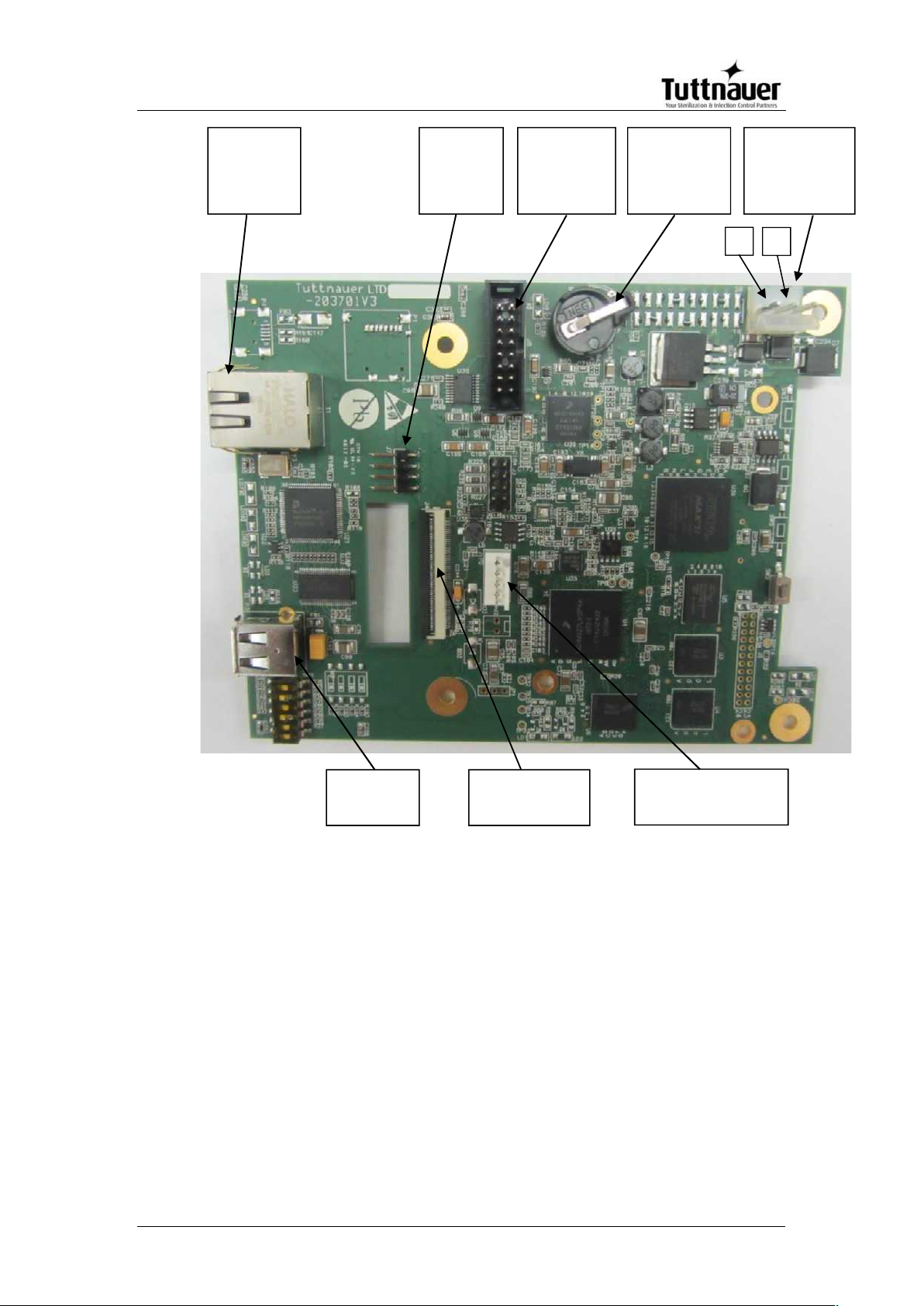
3.3.2 I/O Board
The I/O board handles all the inputs and outputs for the machine. The
I/O board does not hold any software and receives all instruction from
the Main board.
Power Supply
Connector
(24V DC)
Connector to
printer
+
Ethernet
Connector
USB
Connector
-
Connector
to IO Board
Connector to
LCD display
Keypad
Connector
Inputs
Battery
Analog inputs

Page 10
3.3.3 Inputs and Outputs
3.3.3.1 Analog inputs
Analog
inputs
Description
Connector
& pin
PT100-1
PT-100 chamber temperature input
J2
Pressure 1
4mA-20mA chamber pressure input
J7/1
Electrode 1
Water level in the chamber
J11/1
Electrode 2
Water level in the reservoir
J11/2
Digital outputs
J14 J13
Connection to
MAIN Board
Digital Inputs
J12
Analog inputs
J11 J7 J2

Page 11
3.3.3.2 Digital inputs
Digital Inputs
Description
Connector& Pin
Door 1 closed
Door closed switch input
J12/1
3.4 Troubleshooting the inputs:
Connector J2 is for the first PT100 temperature input
Disconnecting the J2 connector will result in the display showing
Analog Input Error and no temperature reading.
Connecting a PT100 simulator (Test -7) can confirm that the control
system is receiving a temperature input signal
Connector J7 is for the pressure sensor input
Disconnecting the J7 connector will result in the display showing
Analog Input Error and no pressure reading.
Inputting 16mA (from an external source) should result in a display
reading of 300 kPa +/- 3 kPa. This will confirm the control system is
receiving a pressure input signal.
Connector J11 is for the water sensor inputs
J11-1 supplies 3.9 VDC to the water sensing electrode in the chamber.
When water level rises to the tip of the sensor the signal is grounded
and the computer knows the height of the water in the chamber.
Note: When the sensor is grounded and the door is closed the door lock will
be engaged. The icon “Water in the Chamber” will be displayed.
Note: Dirt on the electrode can cause the system to fill the chamber with too
little water, resulting in a failed cycle.
Note: Dirt on the sensor can falsely indicate water in the chamber at the end
of the cycle, causing the door to remain locked.
The output at J11-1 or the tip of the electrode can be read as 3.9 VDC
to ground.
Shorting J11-1 or the tip of the electrode to ground will produce the
“Water in the Chamber” icon on the display AND, if the door is
closed, the door lock will be engaged.
J11-2 supplies 3.9 VDC to one of the water sensing electrodes in the
reservoir. The other electrode is connected to ground. When water

Page 12
touches the electrodes the signal is grounded and the computer knows
the height of the water in the reservoir.
The output at J11-2 or the black wire of the electrode can be read as
3.9 VDC to ground, when the reservoir is empty.
With the reservoir empty, shorting J11-2 to ground or shorting across
the reservoir electrodes will remove the “Fill Reservoir” icon from the
display.
Note: Dirt accumulation between the electrodes in the reservoir can short the
signal to ground and make the system think there is water in the
reservoir when it is empty.
With the reservoir full, removing either the black or green wire from the
connector on the outside of the reservoir will produce the “Fill
Reservoir” icon on the display.
Connector J12 contain the DC input from the door switches
J12-1 is the input for both door switches. The door switches are wired
in series so if either one is open the “Door Open” icon will be
displayed.
J12-1 needs to see +24 VDC to know the door is closed.
-
3.4.1.1 Digital outputs
Digital
Outputs
Description
Connector
& Pin
Door unlock
Energizes the door lock solenoid
and unlocks the door
J13/4
Chamber heat
Energizes the SSR that controls
the chamber heaters
J13/6
Water pump
relay
Energizes the water pump relay
that controls the fill solenoid & the
water pump
J13/10
Air Pump relay
Energizes the air pump relay that
controls the air pump solenoid &
the air pump
J13/12
Slow exhaust
Energizes the slow exhaust valve
J14/6
Fast exhaust
Energizes the fast exhaust valve
J14/8

Page 13
3.5 Troubleshooting the outputs:
Connector J13 contains the DC outputs
Utilizing the Test Digital Outputs option (under technician code 0321)
allows you to turn the outputs on and off to verify the component
operation.
With the J13 connector in place, inserting the probe from a DVM into
any of the listed positions will show a reading of +24VDC with respect
to ground when that component is toggled on.
J13-1 is the +24 VDC input to the circuit board from the power supply
at the top of the electronic box.
J13-4 is the DC output to the electronic door lock solenoid
J13-6 is the DC output to the SSR that controls the heating elements
J13-10 is the DC output to the mechanical relay coil #1 that controls
the water pump and water fill solenoid.
J13-12 is the DC output to the mechanical relay coil #2 that controls
the air pump and air pump solenoid.
Connector J14 contains the AC outputs
Utilizing the Test Digital Outputs option (under technician code 0321)
allows you to turn the outputs on and off to verify the component
operation.
With the J14 connector in place, inserting the probe from a DVM into
any of the listed positions will allow a reading of +18VAC with respect
to the red lead on JP3 as the component is toggled on and off.
J14-1 is the 18 VAC input to the circuit board from the toroidal transformer at
the back of the machine.
J14-6 is the AC output to the top/slow exhaust solenoid
J14-8 is the AC output to the fast exhaust solenoid
4.2.4 Power Supplies
3.5.1.1 Toroidal step down transformer
The incoming 120VAC is stepped down to 18VAC by the toroidal
transformer at the back of the unit.
Since it is a step down transformer if the 120 volt input fluctuates up or
down then the 18 volt output will also fluctuate up and down.

Page 14
The only function of the transformer is to supply voltage for the coil of
the solenoid valves.
Even though this transformer is protected by the ON/OFF – Circuit
Breaker it also has an input and output fuse.
The input fuse is a 5x20 mm T1AL time delay fuse
The output fuse is a 5x20 mm F5AL fast acting fuse
If the input or output fuses on the transformer fail then the solenoids
will not function even though the rest of the machine will.
3.5.1.2 PS-1 24VDC Power Supply (at the top of the electronic box)
PS-1 provides 24VDC to the Main board, the I/O board, the pressure
transducer and the electronic door lock, door switches and the relays
which control the water filling, drying and heating.
The PS-1 has an adjustment screw that is set at the factory and should not be
field adjusted.
This power supply is protected by the main ON/OFF – Circuit Breaker located
on the right side of the front panel.
3.5.1.3 PS-2 24VDC Power Supply (at the bottom of the electronic box)
PS-2 provides power for the fan and the optional printer.
The PS-2 has an adjustment screw that is set at the factory and should
not be field adjusted.
This power supply is also protected by the main ON/OFF – Circuit
Breaker located on the right side of the front panel.

Page 15
3.5.2 Mechanical Relays
There are two mechanical relays, one for each of the pumps (air pump
and water pump).
The relays are in sockets so they can be easily replaced.
The relays have two sets of contacts. One set turns the pump on and
off. The other set allows the solenoid valve for that pump to open and
close.
The relay coil receives a 24VDC signal voltage from the I/O board and
the contacts close to allow the 120VAC to pass through and operate
the pump. At the same time it also allows the 18VAC to pass through
and open the solenoid valve.

Page 16
3.5.3 Sold State Relay
The SSR is used to control the heating elements
The SSR receives a 24VDC signal voltage from the I/O board and
closes to allow the 120VAC to pass through to the heaters.
The SSR is located in the electronic box below the mechanical relays.
3.5.4 AC solenoid valves
There are 4 solenoid valves that operate on 18 volts AC. Reading
across the orange and black wire at the coil connection will show
18VAC when the coil is on and about 10VAC when it is off.
The Slow and Fast Exhaust solenoids work directly off the I/O board
J14. The Water Pump and Air Pump solenoids work through the
mechanical relays for the pumps.
3.5.5 Water Pump
The Water Pump is a 120VAC pump and works off Mechanical Relay
#1.
The line voltage to the pump is protected by fuse #1 (2A).
3.5.6 Air Pump
The Air Pump is a 120VAC pump and works off Mechanical Relay #2.
The line voltage to the pump is protected by fuse #2 (2A).
3.5.7 Electronic Door Lock
This unit is mandated to have an electronic door locking system.
The door lock is a 24VDC solenoid with a spring loaded locking pin.
When the solenoid is activated it retracts the pin and the door is
unlocked.
The locking solenoid is mounted in a vertical position with the spring
loaded pin at the top.

Page 17
3.5.8 Door Switches
The door has and upper and a lower door switch to ensure that the
door is properly closed before the cycle can start.
The door switches are in series so if one switch is open the door is
considered unlocked and the cycle will not start.
3.5.9 Heaters
There are two 120 volt 700 watt heaters that wrap around the chamber.
They have wire leads that are connected in a ceramic block by the
electronic box.

Page 18
1
THE039-0037
JP2 ceramic heater connector
3.5.10 Temperature Sensor
The temperature sensor is a PT100 mounted inside the chamber at the
bottom rear.
3.5.11 Pressure sensor
The pressure sensor is a Tecsis P3297 with an output of between 4 –
20ma. It is located at the back of the machine and is connected by
copper tubing to the rear manifold at the top of the chamber.
1

Page 19
3.5.12 Safety Thermostats
There are two safety thermostats. The Cut-Off and the Temperature
Safety Thermostat. They are mounted at the back of the machine with
probes that are mounted under the rear most heating element. They
are connected in series and monitor only the heating element circuit.
3.5.13 Fuses
There are four fuses.
1. Two fuses for the Toroidal Transformer, one input and one output. The
input fuse is 1A Time Delay (T1AL) and the output fuse is a 5A Fast
Acting (F5AL).
2. Two fuses for the pumps. One for the air pump and one for the dry
pump. The pump fuses are 2A each.
3.5.14 Circuit Breaker
The Circuit Breaker is also the On/Off switch and is located on the right
side of the machine at the front.

Page 20
4 Checking and Changing Parameters
and Other Data
This section shows how to access system data and modify parameters.
The Cycle Parameters directory containing parameters for controlling
the sterilization process is locked for programs 1 thru 4 and not
available for modification from the default values (except for drying)
Program 5 is a cleaning program and all parameters are locked.
Program 6 is a calibration program for use by a technician and all
parameters are locked.
Two programs are available for the user to modify as needed, Custom
A and Custom B. These custom programs are not FDA cleared and it is
the user’s responsibility to validate these programs.
Spore testing is your only assurance of complete sterilization.
Once entering the programming mode, the technician will see and have
access to the following directory items.
Directory
Subdirectory
Quick Options (does not require
login) see sec. 4.3 in this
manual and 7.1 in the Operator
Manual
Add extra dry time
Export to USB
Print cycles
Version information
Start cycle by clock
Set date and time
Login
Exit
Main Menu
(requires
login) see
sec. 4.4
Cycle Parameters
for all programs
individually
Temperature sensors (not used)
Displayed Inputs
Drying (see Operator Manual)
Cycle Parameters
– applicable only
for Custom
programs (except
Dry Time)
Cycle Parameters (see Operator Manual)
System
Parameters See
Print Rate All (see Operator Manual)
Print Rate Sterilization (see Operator Manual)

Page 21
sec. 4.7
Screen Saver (see Operator Manual)
Pressure Calibration High (not used)
Pressure Calibration Low (not used)
Temperature Calibration High (not used)
Temperature Calibration Low (not used)
Water Quality Level
Cycle Print Gap (see Operator Manual)
Inputs/Outputs
View digital inputs state
View digital outputs state
Test digital outputs
View analog inputs state
Analog inputs calibration
Maintenance See
sec. 4.9
Export gain and offset to USB
Input gain and offset from USB
Reset atmospheric pressure
Test RTC
Printer test (see Operator Manual)
Print all gain and offset(see Operator Manual)
Advanced Options
Enable cycles
Set language (English)
Set temperature units (ºF)
Set pressure units (Psig)
Duplicate cycle
Delete custom cycles
Set external IP-address (DHCP)
Version Handling
Import application from USB
Import all settings from USB device
Import application and settings from USB
Return to factory default settings
4.1 Browsing through the menus
The following example will show you how to browse through the
directories and subdirectories and change parameters. This is all done
by using the three button keypad.

Page 22
The keypad functioning is a follows:
1. Pressing the UP and DOWN keys simultaneously for 1-2 seconds will
allow access to the menu options.
2. Use the Up and Down keys to advance the cursor and scroll through
the menu.
3. Press the Start/Stop key to select and enter the menu selection that is
highlighted.
4. Repeat steps 1 and 2 to enter the next menu selection until you get to
required screen.
5. When no menu selections are available, as in a parameter screen, the
keys are reversed. The Start/Stop key will advance the cursor and the
Up or Down key will select the highlighted item.
Below are the example screens for the following menu (this option will
normally require a Technicians code 0321 to login) Cycle
Parameters\ Drying\ Dry Time:
Note: To exit every screen and to return to the previous screen (to move one
level up):

Page 23
move the cursor to Exit by pressing the UP or DOWN keys and then
press the Start/Stop key.
- or-
press the UP and DOWN keys simultaneously.
In the next section you will see how to make changes to a parameter.
4.2 Modifying any Parameter
You have browsed through the menus and reached the parameter
changing screen as explained above. Now you can change the
selected parameter as needed. To do so:
1. Enter the required value as follows:
Press the Up and Down keys to change the value of the digit.
Press the Start/Stop key to move the cursor to the next digit to the left.
2. When finished, press the Start/Stop key repeatedly until you move the
cursor to Set.
3. Press the Up or Down key to confirm the new value and to exit the
parameter changing screen.
Below is the typical parameter changing screen:
Note: Please note the maximum and minimum values for this parameter
shown on the screen. Your value must be within these boundaries.

Page 24
Below is the example of changing the Dry time parameter on the
screen used in the previous section:
Note: To exit every screen and to return to the previous screen:

Page 25
move the cursor to Exit by pressing the UP or DOWN keys and then
press the Start/Stop key
- or-
press the UP and DOWN keys simultaneously
4.3 Quick options screen
When the autoclave is on and no cycle is running, press the Up and
Down keys simultaneously to enter the Quick options screen.
The Quick options menu offers easy access to the most frequently
used features. All other options require logging in and their availability
depends on your level of access (user code 0001 or technician code
0321).
Below you can find instructions how to login and enter the Main menu.
Section 7.1 above explains how to browse through the menus; section
7.2 explains how to change a parameter.
Note: A complete explanation of the Quick Options menu can be found in the
EZPlus Operator Manual.
4.4 Logging in and entering the Main menu
Below you can find instructions how to login and enter the Main menu.
Section 4.1 above explains how to browse through the menus, section
4.2 explains how to change a parameter.
When the autoclave is on and no cycle is running, press the up and
down keys simultaneously to enter the Quick Options screen (see 4.3).
On this screen you can proceed to login .To login as technician:

Page 26
1. On the Quick Options screen, choose login.
Select user screen appears.
2. Choose Technician, then press the Start/Stop key to enter. The following
screen will appear:
0000 is displayed on the screen with the cursor flashing on the right
digit.
Set the code to 0321. You will get to the Main menu.

Page 27
Below is the list and the explanation of the options available on the Main
Menu.
4.5 Directories and subdirectories
Bacsoft control panel provides an interface that consists of control
screens available through an easy scrollable menu tree.
To learn how to scroll through the menus, change the parameters,
and perform some other functions using our three-button keypad,
see 4.1 and 4.2.
The following chapter explains meaning and usage of the control
screens.
4.6 Cycle Parameters (cycle specific)
4.6.1 Temp Sensor – this option is not used in this machine
4.6.2 Display Inputs – The screen space on the right consist of three
display positions. The display position of the temperature and pressure
can be changed using this parameter
4.6.3 Drying – Allows for changing the amount of drying time. The Wrapped
and Handpiece cycles cannot be reduce below their default valve.
4.7 System Parameters
This menu is listing the system parameters that are the same for all
cycles. Browse to the following folder:

Page 28
Main menu\System parameters
You will see the following screen:
Brief description of system parameters
Print Rate all – defines the printing rate during all stages of the cycle
except the sterilization stage. This feature requires a printer to be
installed.
Print Rate Sterilization – Defines the printing rate during the
sterilization stage. This feature requires a printer to be installed.
Screen Saver – defines the time interval from the last use of the
Keypad until the screen saver is activated. Setting this parameter to 0
minutes will disable the screen saver.
4.7.1 Pressure Calibration High – not used in this machine
4.7.2 Pressure Calibration Low - not used in this machine
4.7.3 Temperature Calibration High - not used in this machine
4.7.4 Temperature Calibration Low - not used in this machine
Water Quality Level – used to set the acceptable quality of the water
in the water reservoir. On a scale of 0 – 4095, 0 being the poorest
quality and 4095 being the best quality. The default setting is 0.
Cycle Print Gap – Defines the number of blank lines to advance at the
end of the cycle.
 Loading...