

Tuttnauer E-Series Technician manual

TECHNICIAN
MANUAL
Electronic Table -Top Autoclaves
models 1730, 2340, 2540, 3140, 3850, 3870
E, EK, EA & EKA
Cat. No. MAN205-0176-000E Rev. E
Tuttnauer Europe b.v., Paardeweide 36, 4824 EH, Breda, P.O. Box 7191, 4800 GD Breda, Netherlands. +31/76-5423510, Fax: +31/76-5423540

TABLE OF CONTENTS
PARAGRAPH PAGE NO.
1 INTRODUCTION ................................................................................................ 4
2 SYMBOL DESCRIPTION ................................................................................... 4
3 TESTS ................................................................................................................... 5
3.1 Installation Tests....................................................................................... 5
3.2 Periodical Tests......................................................................................... 5
4 WATER QUALITY............................................................................................... 6
4.1 Water for Generating Steam .................................................................... 6
4.2 Reverse Osmosis........................................................................................ 6
5 IN-OUT TEST ...................................................................................................... 7
6 TROUBLESHOOTING........................................................................................ 8
7 REPLACEMENT OF COMPONENTS ............................................................ 14
7.1 Safety Tests after Repair......................................................................... 14
7.2 Replacing the Safety Valve..................................................................... 15
7.3 Replacing the Air Relief Valve ............................................................... 16
7.4 Replacing the Air-Relief/safety-relief Valve block ................................ 17
7.5 Dismantling the Outer Covers of the Autoclave.................................... 18
7.6 Replacing Heating elements................................................................... 19
7.7 Replacing the Temperature Safety Thermostat..................................... 20
7.8 Replacing the Cut-Off Thermostat......................................................... 21
7.9 Cleaning and Replacing the Water Level Electrodes............................ 22
7.10 Replacing the Drain Valve ..................................................................... 23
7.11 Replacing the Pressure Gauge ............................................................... 24
7.12 Replacement of the Door Cover ............................................................. 25
7.13 Replacing the Printer.............................................................................. 26
7.14 Replacing the Door Switch..................................................................... 28
7.15 Cleaning water inlet strainer.................................................................. 29
7.16 Replacing the circuit breaker ................................................................. 30
7.17 Fuses and Circuit Breaker Data ............................................................ 31
7.18 Replacing the water pump ...................................................................... 32
7.19 Replacing the Door Bellows ................................................................... 33
7.20 Replacing the Electronics Box ............................................................... 34
7.21 Validation................................................................................................ 35
8 DESCRIPTION AND FUNCTION OF DIP-SWITCHES............................... 36
8.1 Changing the parameters ....................................................................... 37
9 TEST POINTS - TABLE AUTOCLAVE (AJUNC 3 BOARD) ........................ 38
10 DETAILED DESCRIPTION OF ELECTRONIC SUB-ASSEMBLIES ......... 39
10.1 PREDG board ......................................................................................... 39
10.2 AJUNC 3 Board...................................................................................... 41
1

TABLE OF CONTENT (Cont.)
PARAGRAPH PAGE NO.
11 CALIBRATION AND TESTING PROCEDURE ................................. 43
11.1 Check-Up of Voltages ............................................................................. 43
11.2 Calibration Procedure ............................................................................ 43
12 LIST OF SPARE PARTS................................................................................... 44
13 PRESSURE VS TEMPERATURE FOR SATURATED STEAM.................... 48
14 VALVES NUMBERING .................................................................................... 56
2

TABLE OF CONTENT (Cont.)
DRAWINGS PAGE NO.
AJUNC 3 Board ........................................................................................................... 42
Vessel Assembly ........................................................................................................... 52
Door Tightening Bolt – Assembly ............................................................................... 53
Outer Cabinet - Assembly ............................................................................................ 54
Water Reservoir............................................................................................................ 54
Water Reservoir............................................................................................................ 55
Water Outlet Strainer................................................................................................... 55
Piping Diagram for Models 1730 E and EK............................................................... 58
Piping Diagram for Models: E and EK Except 1730 ................................................ 59
Piping Diagram for Models: EA And EKA ................................................................ 60
Electrical Diagram for Models 1730 E, EK................................................................ 60
Electrical Diagram for Models 1730 E, EK................................................................ 61
Electrical Diagram for Models 2340/2540 E, EK....................................................... 62
Electrical Diagram for Models 2340/2540 EA, EKA ................................................. 63
Electrical Diagram for Model 3140 E......................................................................... 64
Electrical Diagram for Models 3850/3870 E, EK....................................................... 65
Electrical Diagram for Models 3850/3870 EA, EKA ................................................. 66
3
1 INTRODUCTION
This manual, together with the operator’s manual, forms the complete edition
of the Operation and Maintenance instructions. This manual is intended for the
use of the technician. It is forbidden for unqualified and unauthorized personnel
to service the autoclave in accordance with the instructions in this manual. Any
unauthorized service may result in the invalidation of the manufacturer’s
guarantee.
The qualified technician shall be an authorized electrician with the right
qualifications in electronics and shall be familiar with the local
technical/electrical regulations.
2 SYMBOL DESCRIPTION
Caution! Consult accompanying documents
Caution! Hot surface.
Caution! Hot steam.
Protective earth (Ground)
Stand by
4

3 TESTS
3.1 Installation Tests
The service technician shall perform the following preliminary
checks before operating the autoclave:
a. Leveling Check
Check that the autoclave is leveled.
b. Leakage current test
Check the precise operation of the earth leakage relay.
c. Continuity Check
Check the continuity of the grounding connection.
d. Safety Check
Check the safety elements; safety valve and the door locking
e. Programs Check
Run basic programs of the autoclave and check the operation
f. Integrity Check
Perform a visual check to verify that there are no dents, scratches,
g. Validation
Validate the sterilization cycles, taking in consideration the
After the above steps are performed, the autoclave is ready for operation.
mechanisms.
sequences, the sterilization parameters etc.
broken gauges, etc.
interface of packaging/goods/autoclave.
3.2 Periodical Tests
ERIOD
1 months Test the safety valve by operating it.
6 months
Year
5 years Observe the closing device for excessive wear
Safety tests (pressure vessel, efficiency, electrical) shall be performed in
accordance with local rules or regulations, by an authorized inspector.
Remove the autoclave’s cover, tighten the heaters’ screws and
electrical connections, valves and connectors in the control box.
Check the continuity of the grounding connections.
Check the temperature and pressure calibration.
Perform validation of the autoclave.
Check the precise operation of the earth leakage relay.
Check that the autoclave is leveled.
Check the safety elements; safety valve, safety and cut-off
thermostats door locking mechanisms.
Run basic programs of the autoclave and check the operation
sequences, the sterilization parameters etc.
Check the water reservoir, piping, plastic parts and electric wires.
Check and tighten the piping joints to avoid leakage.
Check and tighten all screw connections in the control box,
heaters and valves and instrumentation.
Calibrate the temperature and pressure once a year or in
reference to local rules or regulations (refer to the section on
Calibration).
TEST
5
Only an authorized technician shall perform the 6-months and yearly tests!
4 WATER QUALITY
4.1 Water for Generating Steam
The distilled or mineral – free water supplied to the sterlizer shall be
according to the table below:
Physical Characteristics and Maximum acceptable contaminants
(In compliance with ISO 11134 and ISO 13683).
Evaporate residue < 15 mg/l
Silica < 2 mg/l
Iron < 0.2mg/l
Cadmium < 0.005 mg/l
Lead < 0.05 mg/l
Rest of heavy metals < 0.1 mg/l
levels in water or steam, for sterlizers
Chloride < 3 mg/l
Phosphate < 0.5 mg/l
Conductivity < 50 µs/cm
pH 6.5 to 8
Appearance Colourless, clean, without sediment
Hardness < 0.1 mmol/l
Compliance with the above data should be tested in accordance with
acknowledged analytical methods, by an authorized laboratory.
Attention:
We recommend testing the water quality once a month. The use of
water that does not comply with the table above may have severe
impact on the working life of the sterilizer and can invalidate the
manufacturer’s guarantee.
4.2 Reverse Osmosis
A Reverse Osmosis system may be used to improve the quality of the
water used to generate steam in the autoclave chamber. The use of
mineral free will contribute to better performance and longer life of the
autoclave.
6
5 IN-OUT TEST
Before performing any trouble shooting on the autoclave, perform an “in-out
test”. In this test the technician tests all the components of the system as follows:
1. Turn on the autoclave.
Note: if, for any reason, one of the parameters is corrupted and out of
range, the autoclave will perform an automatic reset to the parameters set
by the manufacturer upon turning on the autoclave.
2. Press the Up button until the autoclave beeps. This beep indicates that the
autoclave is in “IN-OUT TEST” mode.
3. Release the button.
4. To proceed, press the UP button. Each time the UP button is pressed the
test advances one step, and the tested component is displayed on the display.
5. When a solenoid is tested, verify that it is activated by touching it with a
screwdriver. If the solenoid is magnetized – it is activated.
6. To stop the IN-OUT TEST press the Up button.
DISPLAYED
NOTICE
WATER V +
WATER PUMP
EXH
ITEM ACTIVATED REMARKS
Water valve + water pump Verify water enters the chamber
Exhaust valve
HEATERS
AIR
WATER P
DOOR L
PUMP
FLOAT 1
FLOAT 0
DOOR 0
DOOR 1
THERM O
THERM 1
PT100
Heating elements
Air valve
Begins heating. Do not maintain for
long time since it works without water.
Water pump Verify you hear the pump is operating.
N/A N/A
Air pump
Water level switch
indicates “no water”
Water level switch
indicates “enough water”
Door switch indicates
“closed door”
Door switch indicates
“open door”
Safety thermostat
grounded
Safety thermostat not
grounded
Verify you hear the pump is
operating.
Change position of the float switch and
verify that the display reflects the
change.
Press and release the door switch and
verify that the display reflects the
change.
Temperature sensor Displays ambient temperature.
PRESSURE
ELECTRODE X
Pressure transducer
Water level electrode
7
Open door and verify ambient
temperature is displayed.
X may vary between 100 and 255.
indicate “no water in chamber”
255
150 indicates “water in chamber” or
“electrode short- circuited”

6 TROUBLESHOOTING
a) At the customer’s location, avoid replacing any component, which is not
connected to a socket or to a flat cable. If necessary, replace the complete
board or box. If problem persists service the autoclave at the service lab.
b) Whenever the AJUNC3 board of the complete electrical assembly
(CB90030) is replaced without replacing the pressure transducer, or after
replacing the pressure transducer, the pressure must be re-calibrated.
c) When working with the autoclave, DISCONNECT the power cord from the
socket or turn the circuit breaker OFF.
6.1 Turning on the system, no response
a) Check the voltage at the terminal (is the power cord damaged?
change the power cord if necessary.
b) Check the flat cable connecting the PREDG and the AJUNC3,
replace it if necessary.
c) Check the circuit breaker, if it is off, turn it on.
d) Check the cut - off position pushes it in and turn it on.
e) Check the power supply input fuse and replace the fuse if
necessary.
If the network input is o.k., the problem must be with one of the
elements along the line, the power supply, the PREDG or AJUNC
boards and the elements they are connected to.
f) Check the voltages by means of connecting the Test board to JP14
on the AJUNC 3 board as detailed in the voltage checking
procedure.
6.1.1 If there is no 12V nor 5V
a) Does the power supply receive the network voltage?
b) Is the power supply output OK? Disconnect the
connector to JP3 (AJUNC3 board) and check for
voltage on the female connector no. 12V at the female
connector indicates a faulty power supply that should be
replaced. At the client’s location replace the whole
electrical box (C B 90030). 12V at that location
indicates that the power supply is functioning and that
the problem is somewhere else.
c) Check the AJUNC3 board. Disconnect the fan (JP5), the
valves (JP2) and the printer (if present). If disconnecting
any of these elements brings up the voltage, that
element is damaged and has to be replaced.
d) Disconnect the PREDG board and the printer from the
AJUNC 3 board. If any of these elements are faulty, 5V
appears as it is disconnected. If there is still no 5V, the
power supply is damaged.
6.2 System is ON - display is lit
If the other LEDS are functioning the display is most likely damaged.
Replace the PREDG board.
8

6.3 System ON, display lit, erroneous or fragmented digits
The reasons for that may be faulty Real Time Clock, displays or
microcontroller. Replace them or replace the complete PREDG board.
6.4 System ON, display lit, digits are not visible
♦ Check for 5 V between TP1and TP17
♦ If yes, calibrate POT 1 on PREDG board.
♦ If digits remain invisible, this may be due to a faulty display or a
faulty microcontroller. Replace them or replace the complete
PREDG board.
6.5 System ON, key responds without beeping
The problem may be with the buzzer or the buzzer driver. Replace the
complete PREDG board, replace the buzzer or transistor 2N2222A, Q1.
6.6 Exhaust valve is always on
The problem could be with the solenoid, the transistors, or the digital
control, or a bad connection.
♦ Check and connect or replace all connections to and from the
exhaust valve.
♦ The problem could be with Q4 or Q5 on the PREDG board. If after
pressing START and the water enters the chamber, the voltage on
TP11 is between 10V - 12V the control and the transistors are O.K.
If not, replace the PREDG board. At this point disconnect connector
JP2 from the AJUNC3 board, and check the valve’s control.
If the connection to the valve is OK, (please refer to the wiring
diagram) there must be a mechanical problem with the valve or the
solenoid may be damaged.
If the control is faulty, check and connect the flat cable between
AJUNC3 and PREDG, replace the cable if necessary. If this does
not help, there may be a problem in the LATCH DRIVE at U4 in
PREDG. In that case the electronics unit should be replaced.
6.7 Exhaust valve is always off
♦ Check and connect or replace the connector between the
EXHAUST valve and the AJUNC3.
♦ Repeat transistors and control checks as in 7.6 but this time the
voltage for the transistors should be vice versa: 0.0-1.0 DC. volt (on
TP11) for open position.
♦ Check and replace the valve or the coil.
6.8 Water valve is always on and there is a continuous flow of water into
the chamber.
♦ Check the valve’s solenoid and the control circuit as you have
checked the respective exhaust valve and circuit. The valve could
also be checked by pressing the MANUAL water inlet key. If water
flows in the chamber, or if there is no flow of water once the system
is initiated, the valve and its control are o.k., but the water level
detector electrode may be damaged, or the connection between the
electrode and the circuit may be bad.
♦ Check wire and connector connecting electrode to AJUNC3 board.
9

6.9 Inlet key does not let water into the chamber
♦ Check if this key is faulty. If it beeps when pressed it is O.K. if not,
replace the keypad. If this does not help, replace the complete
PREDG and keypad unit.
♦ Check the float at the water reservoir by manipulating it using a
screwdriver or a tool and repair/replace it. If the float is
functioning, the problem could be with the control circuit at the
PREDG board: the test board between TP1 (GND) and TP10 (water
valve): GOOD = 0.0V to 0.05V.
♦ If the control is OK, there may be a problem with the valve itself or
with its connector.
♦ Check and replace the coil if necessary.
6.10 Pressure stays close to 100 kPa (0 psi), temperature does not exceed
°
110 - 115
C (207°F) or, water inlet lasts a longer time than usual
This phenomenon is most likely due to malfunction of the air valve. The
air valve’s normal operation is as follows:
OPEN whilst turning the system on, OPEN throughout WATER INLET
and HEAT until temperature has reached 90°C or 194°F, CLOSED from
that stage on, and OPEN during DRY.
The valve’s control on the AJUNC3 board should act as follows:
0.0V = valve OPEN
5.0V = valve CLOSED
If the problem lies on the AJUNC 3 board it should be replaced. It is
recommended to replace both the AJUNC3 and the solenoid because a
damaged solenoid may affect the AJUNC3 board. If the control circuit
on the AJUNC3 is OK, the problem is probably with the PREDG board.
6.11 Heaters are always ON or OFF
Warning: If you need to tighten a screw, make sure to do so only when
the power cord is disconnected.
♦ Check the heaters connections.
♦ Check the cutoff thermostat position and turn it clockwise to the end.
♦ Check the control at TP1 and TP12 for ON = 0.0V, OFF = 5v
♦ Check connections between AJUNC3 to SSR at TP4.
♦ Does AC voltage enter the SSR at AC connector and SSR pin 2?
♦ Is SSR output the AC voltage? Check AC connector and at SSR pin 1.
♦ Is the control OK? Check the SSR for 5.0V between pins 3&4. If
control is OK, but SSR output is not the AC voltage, replace the
SSR.
6.12 Heaters o.k. but autoclave does not reach sterilization temperature
♦ Check and calibrate the cutoff position.
♦ Check and clean/ replace leakage at the exhaust valve.
♦ It is also possible that there is a calibration variance, check the
GAIN pressure calibration, perhaps it should be lowered or, the
GAIN temperature should be increased.
♦ Another possibility is that insufficient water level in the chamber
does not allow the pressure to build up. Check the water level
detector electrode, or the leveling of the autoclave.
10

6.13 Fan is not on during the cycle
♦ Check and connect properly the FAN’S connector at JP5 on the
AJUNC3 board.
♦ Disconnect FAN and check the control TP1 and TP-13:
ON = 0.0V OFF = 5.0V
6.14 Pressure display is incorrect (discrepancy between ANALOG and
Digital displays)
♦ Re-calibrate the displayed pressure by manipulating POT2 on the
AJUNC3 board.
♦ Check the MPX2200A pressure transducer between TP2 & TP3:
♦ Working condition = 20mV for 100 kPa.
♦ If pressure transducer is faulty, replace it, and calibrate it according
to the instructions in the Chapter on Calibration.
♦ If the pressure transducer is OK but display incorrect, replace the
AJUNC3.
6.15 Temperature display is incorrect
♦ Check the temperature sensor PT100.
♦ Check the calibration of the temperature circuit.
6.16 ADD WATER (to reservoir) Indicator is always ON
♦ Check the connector at JP2 on AJUNC3 board.
♦ Check if the float at the water reservoir is stuck.
♦ Check the input: TP1 and TP8 FULL = 0.0V, EMPTY = 5.0V
♦ Check the float’s buffer, it may be, the input at U5 on PREDG is
damaged. PREDG board should be replaced.
6.17 DOOR CLOSED indicator is always ON/OFF
♦ Check and fine tune the switch at the upper front left side of the
autoclave, while the door is open. Check the switch with an
ohmmeter. If the microswitch is damaged, replace it.
♦ Check the LED, if it is burnt, change the PREDG and keypad.
♦ Check the connector between microswitch and AJUNC3 on TP2.
♦ Check the connection on GND to the microswitch with an
ohmmeter and be sure that the GND to the micro switch.
♦ If the switch and microswitch are OK, buffer at U5on PREDG may
be damaged, in that case, replace the PREDG board.
Note:
If replacing the microswitch is necessary, VERIFY THE ELECTRIC
CORD IS DISCONNECTED.
6.18 Start key does not let water into the chamber
♦ Follow previous procedures for float, controls and valve.
♦ Check the water level electrode: Connect TP1 and TP6, close the
door, press START.
♦ If 4V the electrode is short circuited or faulty. Same procedure may
be followed without pressing START, if the door is open.
11

6.19 Back-up memory does not function does not function, new parameters
are not stored in memory
♦ The backup battery in the Real Time Clock is damaged so
component U2 should be replaced.
6.20 LOW PRESSURE message is displayed
This is usually due to insufficient water inside the chamber.
♦ If the water valve is OK, the electrode detecting the water level may
be damaged. It may detect water in the chamber although it is
actually empty.
♦ The normal operation procedure of the electrode is to let water in
the chamber 8 additional seconds after it has detected a sufficient
water level.
♦ If the electrode is short circuited, it may let water into the chamber
for only a few seconds.
♦ Check if there is any contact between the electrode and the
chamber. Use an ohmmeter for that purpose. Make sure none of the
tools to be sterilized has any contact with the electrode. If the
problem persists, the electrode circuit on the AJUNC3 board may
be short circuited or damaged.
6.21 Clock and date are inaccurate, new data is not stored in memory
♦ If new data (operator’s own parameters) is not kept in memory, then
the backup battery is down, and the same unit has to be replaced as
the backup battery is an integral part of the Real Time Clock.
Change the Real Time Clock (U2), on PREDG.
♦ The battery manufacturer offers a ten-year guarantee, but it is
recommended to change the Real Time Clock including the
integrated backup battery once every 8 years.
6.22 Unpredicted function of the autoclave
♦ Check the input and output voltages. Disconnect the printer as it
may be causing a short circuit if it is faulty. If the problem persists,
the keypad may be short circuited, replace it with the PREDG
board, if that does not help, replace the complete electronic system.
6.23 Displaying of low temperature
If LOW TEMPERATURE is displayed, the following should be
checked:
1. The proper amount of water is in the chamber.
2. The air jet has to be checked and cleaned.
12

6.24 Memory reset
To reset the memory of the autoclave control unit backed up by a
battery, proceed as follows: Verify that there is no pressure in the
autoclave chamber.
1. Turn the main switch to OFF position.
2. Press the STOP key. At the same time turn the main switch to ON
position.
3. Keep pressing the STOP key until the program parameters are
displayed.
4. Set the Sterilization temperature, Sterilization time, Date and Time.
5. Repeat the procedure of automatic water filling.
6.25 Cycle counter reset
To reset the cycle counter proceed as follows:
1. Press the STOP key a few times, till CODE 102 is displayed.
2. Press the UP key (8) up to CODE 134.
3. Press any key to continue.
The counter is now reset.
6.26 EKA ONLY - Air pump and valve always ON or OFF
♦ Check the S.S.R2 in the electric box.
♦ Check if TP 18 is in 0.0V if on and 5.0V if off, if yes replace
PREDG.
If not replace the AJUNC3 board.
6.27 EKA - Air pump is always on, valve is off
♦ The problem is in the pump or in SSR2 located in the electric box.
6.28 Pump is operating but no or low water flow.
Check pipes connecting the water reservoir, strainer and pump.
1 Air accumulates at the pump inlet. Disconnect pipe from the pump,
let water flow to remove air accumulation and reconnect pipe.
2 Pipe is clogged. Clean pipe.
3 Strainer is clogged. Clean strainer according to instructions.
6.29 Water does not exit chamber.
Outlet strainer is clogged. Clean strainer according to instructions.
13

7 REPLACEMENT OF COMPONENTS
7.1 Safety Tests after Repair
ATTENTION!
After every repair or dismantling the enclosure, the autoclave
should pass two safety electrical test by the Service Engineer. The
following shall be performed:
1. Enclosure Leakage Current Test.
Every autoclave should pass this test as follows:
1. Connect the electrical cord to the autoclave.
2. Turn on the main switch and the circuit breaker.
3. Short-circuit the L and N pins on the cord's plug.
4. Connect the Short-circuit pins to the L pole on the Megger.
5. Connect the earth pins to the earth pole on the Megger.
6. Impose an electrical potential of 500-1000V on the tested
autoclave. The insulation resistance should be at least 2 MΩ.
The test is successful if there was no leakage.
2. Protective Earth Impedance Test
1. Connect the grounding pin of the power cord plug to one pole of
an Ohmmeter.
2. Connect any other metallic part (preferable – the metallic part of
the locking screw) to the second pole of the Ohmmeter.
3. The resistance should not exceed 0.3 Ω.
After performing these tests, the Service Engineer should complete and
sign the Work Order.
14
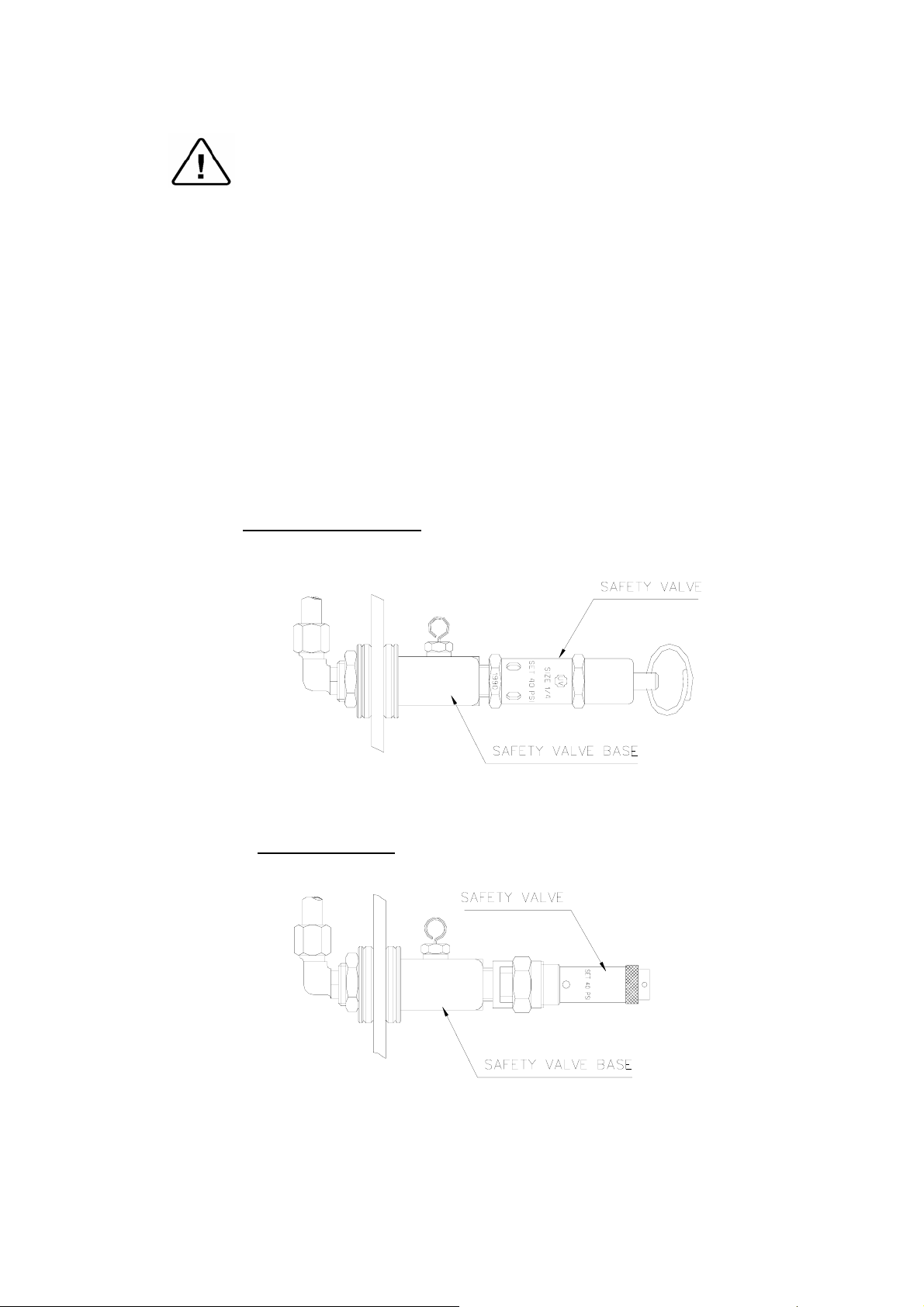
7.2 Replacing the Safety Valve
Caution!
Before starting, be sure that the electric cord is disconnected and that
there is no pressure in the autoclave.
These instructions are valid for both, PED and ASME type safety
valves.
1. Remove the autoclave cover (see para. 7.5 “Dismantling the Outer
Covers of the Autoclave”).
2. Remove the water reservoir cover.
3. Unscrew the safety valve and remove it from the safety valve base.
4. Replace the valve with a new safety valve (install an original
only!). Use Teflon tape for sealing the thread.
5. Perform one cycle and verify that the valve operates correctly.
Typeapproved ASME
TypeCE marked
15
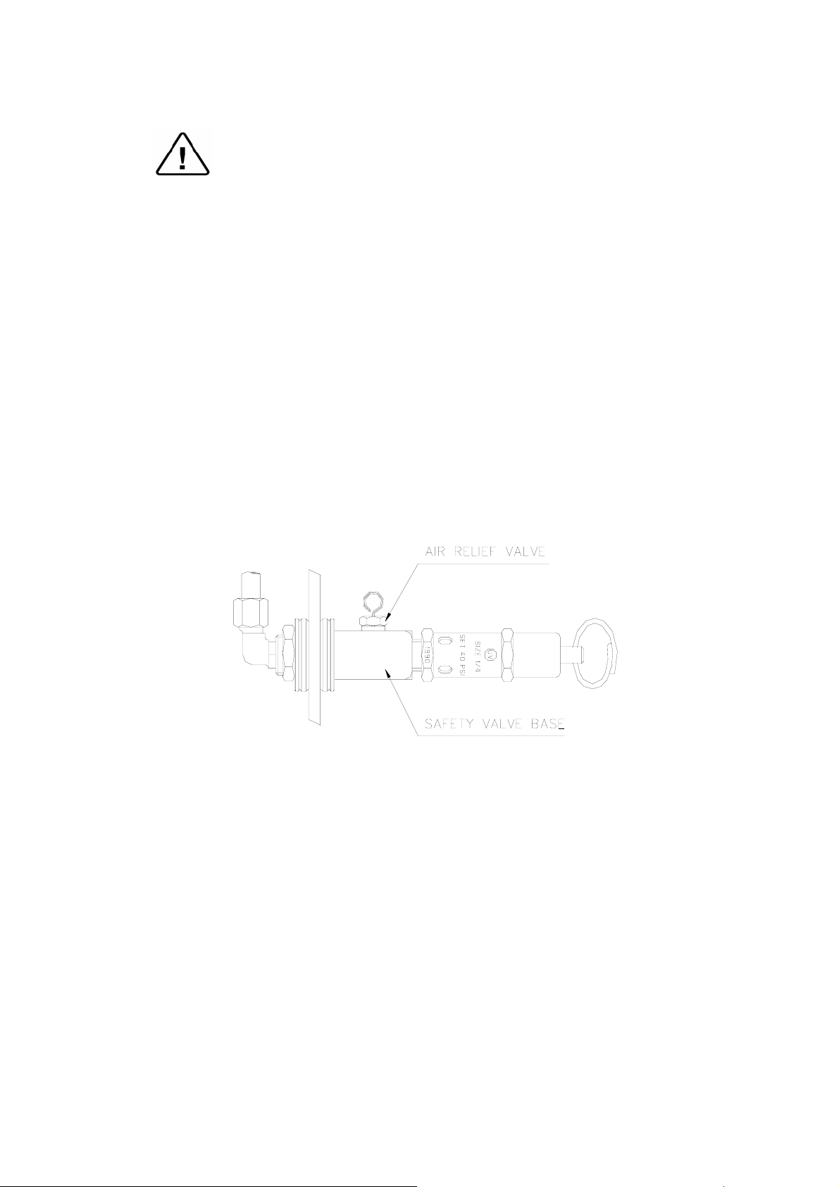
7.3 Replacing the Air Relief Valve
Caution!
Before starting, be sure that the electric cord is disconnected and that
there is no pressure in the autoclave.
1. Remove the autoclave cover (see para. 7.5 “Dismantling the Outer
Covers of the Autoclave”).
2. Remove the water reservoir cover.
3. Remove the water reservoir silicon gasket.
4. Unscrew the air relief Valve with a 10 mm wrench and remove it
from the safety valve base.
5. Replace the valve with a new air relief (install an original only!).
use Teflon tape for sealing the thread.
6. Test any autoclave cycle to verify that the valve operates correctly.
16
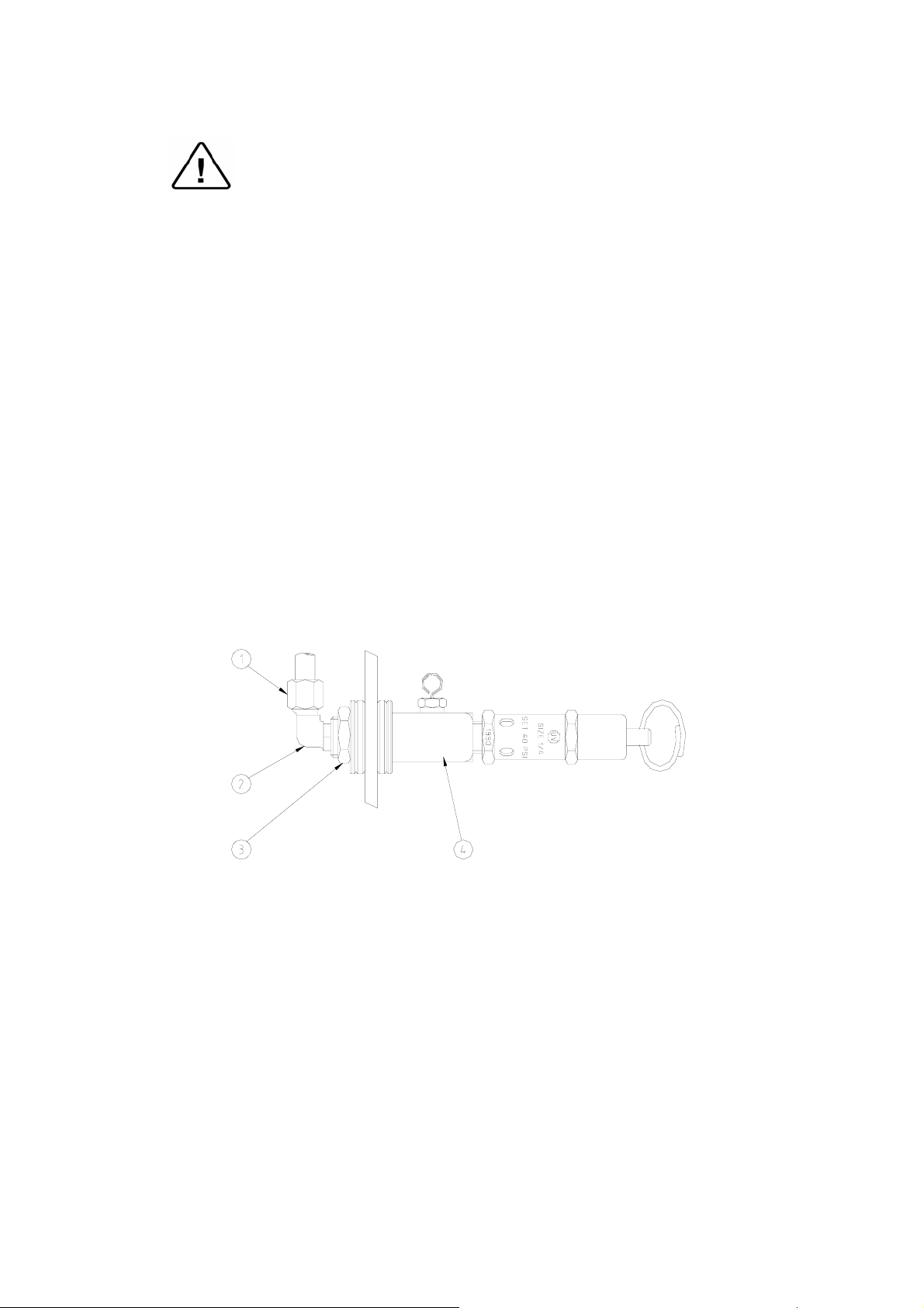
7.4 Replacing the Air-Relief/safety-relief Valve block
Caution!
Before starting, be sure that the electric cord is disconnected and that
there is no pressure in the autoclave.
In case the water reservoir is deeply contaminated (soil, lime stone. etc.)
it is recommended to replace the entire unit.
1. Remove the autoclave cover (see para. 7.5 “Dismantling the Outer
Covers of the Autoclave”).
2. Remove the water reservoir cover.
3. Remove the water reservoir silicon gasket.
4. Unscrew and remove nut (1) with a ½” wrench.
5. Remove angle 1/8”-1/4” (2) from the relief valve base.
6. Unscrew and remove nut (3).
7. Remove the air-relief-safety valve block (4).
8. Install the new unit using Teflon tape for sealing the thread.
9. Perform one cycle and verify that the valve operates correctly.
L:\\.doc
17
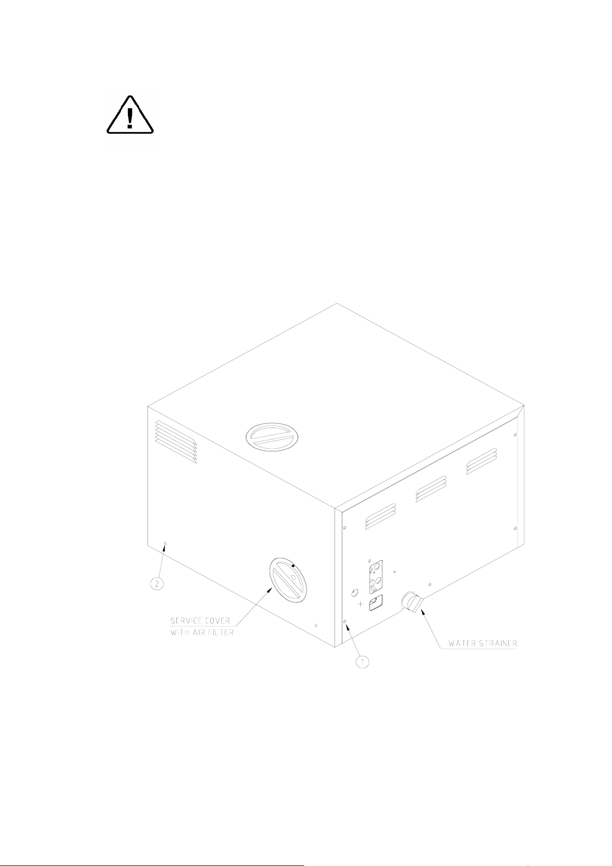
7.5 Dismantling the Outer Covers of the Autoclave
Caution!
Before starting, disconnect the instrument from the power source
and ensure that there is no pressure in the autoclave.
Allow the autoclave to cool before removing outer covers.
1. Remove the screws holding the rear cover (1).
2. Remove the screws holding the cover to the base (2).
3. On EA and EKA models dismantle the air filter from the service
opening cover (3).
3.1. Remove the screws holding the filter cover (on EA, EKA).
4. Remove the grounding wires from the cover.
5. Pull the cover upwards.
18

7.6 Replacing Heating elements
Caution:
Before starting, be sure that the electric cord is disconnected from the
power source and that there is no pressure in the autoclave chamber.
1. Remove the autoclave cover (see para. 7.5 “Dismantling the Outer
Covers of the Autoclave”).
2. Remove the insulation.
3. Remove the heating element tightening bolts (1).
4. Release the two terminal wires from the heating element.
5. Replace the heating element (s)
5.1 verify that the thermo-couple upper tube is connected to the
upper (cut-off) thermostat and the lower thermo-couple to the
lower (safety) thermostat.
6. Ensure that the heating element strap is well tightened to the
autoclave body, ensuring proper heat dissipation from the heating
element.
7. Re-assemble the autoclave insulation and cover.
8. After replacing one or more heating elements run a cycle and verify
that it operates as required.
9. Retighten the fixing screws of the heaters. This operation is done
with the autoclave hot, but with the power cord disconnected from
the power outlet and autoclave door open, to ensure that the
chamber is not pressurized.
10. Re-assemble the autoclave’s cover.
11. Test the autoclave by performing a full cycle.
L:\WORD-PLT\MAN235.doc
19
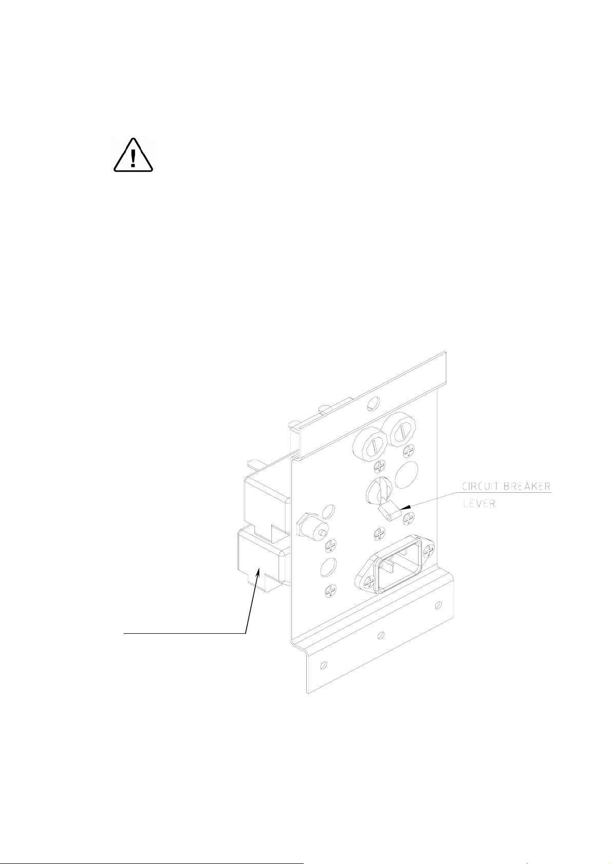
7.7 Replacing the Temperature Safety Thermostat
The autoclave is supplied with a temperature thermostat, which protects
the heaters and autoclave against overheating, during the dry cycle.
This device reconnects automatically when the chamber cools down.
Caution
Before starting, disconnect the instrument from the power source and
ensure that there is no pressure in the autoclave.
Allow the autoclave to cool before removing outer covers.
The temperature safety thermostat is located on the lower side of the
fuse and socket panel on the rear of the autoclave.
1. Remove the rear cover.
2. Loosen the heating band.
3. Unscrew the thermostat and replace it with a new one.
4. Perform any dry cycle to verify that the temperature safety
thermostat disconnects the heating units.
Safety Thermostat
20
 Loading...