

Tuttnauer E-Series Repair manual (2008)

Technicians Service and
Repair Manual
for
Tuttnauer Automatic
Autoclaves
Models E, EK, EA, EKA, EZ and EZ10K
Cat. No. MAN205-0310001EN Rev. C
Tuttnauer USA Co., Ltd., 25 Power Drive, Hauppauge, NY 11788, USA, : (800) 624 5836, (631) 737 4850, Tech Service ext. 772,
Fax: (631) 737 0720, Tech Service fax (631) 737 4855
e-mail: info@tuttnauerUSA.com


This manual is intended for the qualified technician. The instructions and guidance go into
great detail, but basic trouble shooting and diagnostic skills are still required.
I want to thank all the members of the technical staff at Tuttnauer USA with out whose
help this manual could not have been completed
Written by Henry Dierschke
Illustrated by Edward A. Hendrickson
Second Edition
Januar 10, 2008
Revised Edition
November 18, 2004
First Edition
June 1, 2000

TABLE OF CONTENTS
PARAGRAPH PAGE NO.
1 General Information..................................................................... 5
1.1 The Tuttnauer Company................................................................. 5
1.2 Warranty .......................................................................................... 6
1.3 Theory of Operation ........................................................................ 7
2 Installation and Setup .................................................................. 9
2.1 Unpacking and Inspection............................................................... 9
2.2 Unit Location.................................................................................... 9
2.3 Voltage Requirements ................................................................... 10
2.4 Setup................................................................................................ 10
3 Front Panel Keypad.................................................................... 14
3.1 Front Panel Keypad....................................................................... 14
4 Display Messages ........................................................................19
4.1 Display Messages............................................................................ 19
5 Operating Instructions ...............................................................23
5.1 Preparation Before Sterilizing...................................................... 23
5.2 Filling The Reservoir ..................................................................... 25
5.3 Sterilization Programs................................................................... 26
5.4 Operating Instructions .................................................................. 29
5.5 Standard Sterilization Temperatures & Times........................... 31
6 Maintenance................................................................................32
6.1 Cleaning the Autoclave.................................................................. 32
6.2 Door Assembly Maintenance ........................................................ 37
6.3 Closing Device Maintenance ......................................................... 38
6.4 Solenoid Valves............................................................................... 39
6.5 Air Jet Maintenance ...................................................................... 41
6.6 Water Sensing Electrode............................................................... 42
6.7 Chamber Maintenance .................................................................. 43
6.8 Dry Pump Filter Maintenance...................................................... 43
6.9 Safety Relief Valve Maintenance.................................................. 43
6.10 Printed Circuit Board Maintenance............................................. 45
6.11 Filter Maintenance......................................................................... 46
1

7 Troubleshooting..........................................................................49
7.1 Power on Problem.......................................................................... 49
7.2 Heat up Problem ............................................................................ 52
7.3 Pressure Problem........................................................................... 55
7.4 Temperature Problem ................................................................... 58
7.5 Keypad Problem............................................................................. 61
7.6 Overheating Problem..................................................................... 62
7.7 Temperature Safety Thermostat Problems................................. 64
7.8 Circuit Breaker or Fuse Problem................................................. 65
7.9 Dry Pump Problem........................................................................ 69
7.10 Drying Problem.............................................................................. 72
7.11 Sterilizing Problem ........................................................................ 75
7.12 Fan Problem ................................................................................... 77
7.13 Odor Problem................................................................................. 79
7.14 Door Problem ................................................................................. 81
7.15 Water Fill Problem ........................................................................ 89
7.16 Leaking Water or Steam ............................................................... 95
7.17 Air Outlet Valve Problem ............................................................. 97
7.18 Display Problem............................................................................. 99
7.19 Power Supply Problem ................................................................ 101
7.20 Control Problem........................................................................... 105
7.21 Printer Problem ........................................................................... 107
7.22 Add Water Indicator Problem.................................................... 109
7.23 Door Closed Indicator Problem.................................................. 111
7.24 Memory Problem ......................................................................... 113
7.25 Exhaust Problem.......................................................................... 114
7.26 Cut-Out Thermostat Problems................................................... 116
7.27 Water Pump Problem.................................................................. 118
8 Testing and Calibration ........................................................... 121
8.1 SSR (Solid State Relay) ............................................................... 121
8.2 Testing Heating Elements............................................................ 124
8.3 Solenoid Valves............................................................................. 125
8.4 Temperature Sensor Calibration................................................ 127
8.5 Pressure Sensor Calibration ....................................................... 130
8.6 Automatic Water Fill Procedure ................................................ 133
8.7 Water Sensing Electrode Testing ............................................... 136
8.8 Temperature Safety Thermostat Testing................................... 138
2

8.9 Cut-Out Thermostat Testing ...................................................... 141
8.10 Dip Switch Selection .................................................................... 142
8.11 Available Test Equipment........................................................... 144
8.12 Finding the Software Version Number...................................... 148
8.13 In-Out Test ................................................................................... 149
9 Tables and Diagrams................................................................ 150
9.1 OHM and AMP Readings ........................................................... 150
9.2 Digital Predg Board ..................................................................... 151
9.3 Ajunc 2 Board Basic Layout ....................................................... 152
9.4 Ajunc 3 Board Basic Layout ....................................................... 153
9.5 Test Points for Ajunc 2 Board .................................................... 154
9.6 Test Points for Ajunc 3 Board .................................................... 155
9.7 Maximum Instrument Load ....................................................... 157
9.8 Maximum Textile Load ............................................................... 158
9.9 Maximum Liquid Load ............................................................... 159
9.10 Schematics .................................................................................... 160
9.11 Power Supply................................................................................ 163
9.12 LM34 Cross Reference Table ..................................................... 164
9.13 Solenoid Valve Schematic............................................................ 165
9.14 Autoclave Rear View ................................................................... 166
9.15 Autoclave Electronic Box Components...................................... 167
9.16 Chamber Brite Cleaning Instructions........................................ 168
10 Replacement.............................................................................. 169
10.1 Heating Element Replacement.................................................... 169
10.2 Temperature Safety Thermostat Replacement ......................... 172
10.3 Temperature Sensor Replacement ............................................. 174
10.4 Pressure Sensor Replacement..................................................... 176
10.5 Power Supply Replacement ........................................................ 177
10.6 Closing Device .............................................................................. 180
10.7 Solenoid Valve Replacement....................................................... 182
10.8 SSR (Solid State Relay) Replacement ........................................ 184
10.9 Air Jet Replacement .................................................................... 185
10.10 Water Sensing Electrode Replacement...................................... 185
10.11 Door Bellows Replacement.......................................................... 186
10.12 Chamber Replacement ................................................................ 188
10.13 Printer ........................................................................................... 189
10.14 Dry Pump Replacement .............................................................. 190
3

10.15 Safety Relief Valve Replacement................................................ 191
10.16 Float Switch Replacement........................................................... 192
10.17 Power Transistor Replacement .................................................. 193
10.18 Ajunc Board Replacement .......................................................... 194
10.19 Digital Predg Board Replacement.............................................. 196
10.20 Door Assembly Replacement ...................................................... 197
10.21 Fan Replacement.......................................................................... 198
10.22 Water Pump Replacement .......................................................... 198
10.23 Fuse and Fuse Holder Replacement........................................... 199
10.24 Circuit Breaker Replacement ..................................................... 199
11 Component Function in the Autoclave ...................................200
11.1 Temperature Safety Thermostat ................................................ 200
11.2 Cut-Out Thermostat .................................................................... 202
11.3 Air Jet............................................................................................ 203
11.4 Water Sensing Electrode ............................................................. 204
11.5 Door Bellows................................................................................. 205
11.6 Air Outlet Valve ........................................................................... 206
11.7 Printer ........................................................................................... 207
11.8 Fuse & Circuit Breaker............................................................... 209
4

1 General Information
1.1 The Tuttnauer Company
The Tuttnauer Company founded in 1925 produces infection control equipment for
the Dental, Medical, Veterinary and Laboratory markets. In addition, Tuttnauer
produces large walk-in units for industrial, commercial and hospital applications.
Tuttnauer equipment is distributed worldwide and the Tuttnauer Company is
considered a leader in the field of Infection Control Apparatus.
Our main product line consists of manually operated and automatic sterilizers. The
following list shows past as well as currently available models of Tuttnauer
sterilizers.
Manually operated models:
M = Manual
MK = Manual Kwiklave*
Chamber sizes: 7” x 12”; 9” x 18”;
(diameter x depth) 10” x 19”; 15” x 30”
and 15” x 27”
Automatic models:
E = Electronic
EA & EZ = Fully Automatic with Air Assisted Drying
EK = Electronic Kwiklave *
EKA & EZ10k = Fully Automatic Kwiklave * with Air Assisted Drying
Chamber sizes: 7” x 12”; 9” x 18”;
(Diameter x Depth) 10” x 19”; 15” x 30”
15” x 27”
Tuttnauer offers a wide variety of standard models of autoclaves, as well as custom
designed units.
Additional Tuttnauer products:
• Chamber Brite autoclave cleaner
• Clean & Simple ultrasonic enzymatic cleaning solution in tablet form
• Ultrasonic Cleaners - 1 & 3 gallon
• Water Distillers – 1gal, 3.5gal, 8gal and 12gal
* Kwiklave units have faster cycle times than a standard unit, while maintaining
standard sterilization exposure times.
5

1.2 Warranty
Tuttnauer’s warranty covers defects in materials and workmanship on every
the autoclave. For exact details, see a formal copy of the Warranty Policy or call
Tuttnauer at 1 800 624 5836.
This warranty covers both parts and labor for new
Tuttnauer warrantee’s chambers (on select models) for a period of ten (10) years
against any defects in materials and workmanship. This chamber warranty went
into effect January 1997, (for more details call 1 800 624 5836).
These warranties do not apply to any improper installation or application; nor shall
it extend to products, which have been altered outside the factory without prior
authorization from Tuttnauer; nor to products, which have been improperly
maintained.
No product will be received or accepted for repair without proper return
authorization from Tuttnauer. All transportation charges to and from Tuttnauer are
the responsibility of the owner of the autoclave. During the first 30 days after
purchasing a new autoclave, Tuttnauer will pay shipping costs on an individually
evaluated basis and ONLY with pre-approval.
This warranty will be void if the unit is not purchased from an authorized
Tuttnauer dealer.
To activate the warranty, the registration card must be completed and returned to
Tuttnauer within fourteen (14) days of purchase or you may call Customer Service
at 1 800 624 5836.
Tuttnauer’s
No other warranties or obligations are expressed or implied.
obligation is limited to repair or replacement of parts for the autoclave.
autoclaves only.
part in
6
1.3 Theory of Operation
Theory of Operation – Electronic Steam Sterilizer Models E, EK, EA, EKA,
The Tuttnauer Steam Sterilizer is designed as a gravity displacement system. This
Water inside the autoclave Chamber is heated to produce steam. The rising steam
EZ and EZ10k
means that no other methods are used to move steam and air in or out of the
Chamber other than the natural forces of gravity.
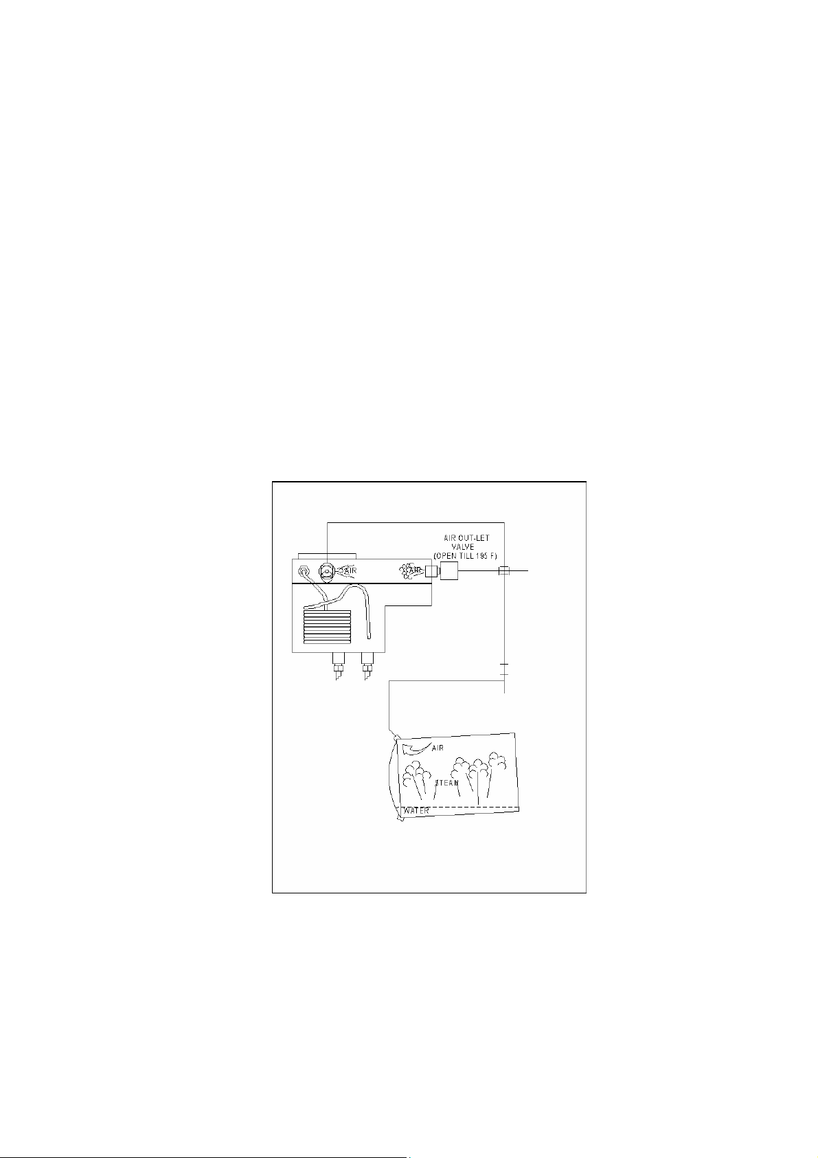
forces any air inside the Chamber to the top of the Chamber where it is bleed off
by the Air Jet. This event is due solely to the effect of gravity on the steam and air.
As the pressure builds within the Chamber, the air is continuously expelled through
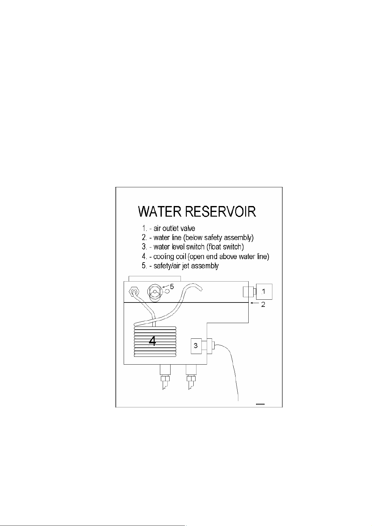
the unit’s Air Jet. The Air Jet is located in the water reservoir and connected by a
copper tube to the top rear of the Chamber. The process of removing the air and
leaving only steam in the Chamber is essential to the operation of the Sterilizer.
Assisting the Air Jet in this function is the Air Outlet Valve. This valve participates
in removing the air until a temperature of 195° is reached then the valve closes and
any remaining air is removed by the Air Jet.
Steam temperature has a direct and important correlation to steam pressure. At
every level of pressure, steam has a specific corresponding temperature; this is a
universally accepted fact. There is one stipulation required to make this true, there
must be 100% steam present. For this reason, it is important that the air be
removed as completely as possible from the Chamber. Removing the air is what
allows the temperature to rise properly inside the Chamber.
7

The importance of a clean working Air Jet cannot be understated. The Air Jet has
two important functions:
First is to remove the air from inside the Chamber while the unit is heating
up. If air were allowed to remain in the Chamber its presence would produce
pockets of low and high temperatures. These uneven temperatures within the
Chamber would result in areas of no sterilization. Only by removing the air
can more uniform temperatures be attained and as a result, even and complete
sterilization.
The Air Jet has a second function, which is to maintain circulation within the
Chamber. It does this by remaining open after all the air has been bled off
and continuing to purge the steam. This constant purging of steam causes
motion within the Chamber. This constantly moving, constantly circulating
steam is important in maintaining uniform temperature. Uneven steam
temperatures can be the result of the heating elements turning on and off
during the sterile cycle. This can cause hot and cold pockets of steam within
the Chamber. If an instrument is in one of these cold pockets, it will not be
sterilized even though the rest of the load was and the spore test confirmed a
sterile load. The end result of keeping the steam in motion, because of the Air
Jet, is that no pockets of uneven temperature will form and the load will be
Why use steam in the first place?
completely sterilized.
There are several reasons for preferring a steam Sterilizer.
♦ The first is that steam is non-toxic.
♦ The second is that steam sterilization is fast. Steam has excellent heat transfer
properties.
Steam allows for tremendous amounts of heat energy to be transferred to the
instruments instantaneously. This flash of energy is what destroys the
biological contamination.
♦ Third, steam is readily available and easy to make from any water source.
♦ Fourth, equipment designed for steam sterilization is simpler to manufacture
Basic operation of the autoclave.
and use.
1. The operator closes the door and presses start.
2. Water flows into the Chamber; the Air Outlet Valve is open so that the water
can flow in smoothly. Water flowing into a hot sealed Chamber will build
pressure immediately, exerting a force on the water that can slow or even stop
it from entering the Chamber. The open Air Outlet Valve provides an escape
for that pressure, releasing that pressure allows the water to flow easily.
3. The autoclave heats to the proper temperature, controlled by the temperature
and pressure sensor. The Air Outlet Valve closes at 195°F. Air escapes the
Chamber through the Air Jet.
4. Once the temperature is reached, the timer counts down the programmed
amount of sterilization time. Steam continues to purge through the Air Jet
eliminating any differences of temperature that can occur within the Chamber.
5. The autoclave exhausts and the sterilization is complete.
8

2 Installation and Setup
2.1 Unpacking and Inspection
Upon receiving the autoclave, carefully inspect the outside of the shipping carton
for any signs of damage. If any damage to the shipping carton is found, note the
location with respect to the autoclave and check that area of the autoclave carefully
once it is fully unpacked. In addition, once the autoclave is fully unpacked,
carefully check for any signs of physical damage such as; scratched panels, broken
knobs, broken door covers, etc…
If any damage is found, contact the dealer as soon as possible so that they can file a
claim with the shipping carrier and also notify Tuttnauer.
All Tuttnauer products are carefully inspected prior to shipment and all reasonable
precautions are taken, in preparing them for shipment, to assure safe arrival at their
destination.
Note: Lifting and carrying should always be done by two people
2.2 Unit Location
The unit should be located on a stable, solid countertop. In the case of the 3850
and 3870 models a table is provided with the unit.
It is not recommended that units be stacked. Adequate clearance is required above
the autoclave for the purpose of filling the reservoir with distilled water. In
addition, some steam escapes through the filling hole. If overhead cabinets are too
close, steam damage can occur to the underside of the cabinets.
A minimum of one inch clearance is required on each side and at the back of the
autoclave for access and ventilation.
Note: Lifting and carrying should always be done by two people
9

2.3 Voltage Requirements
All 110 volt units need to have a stable voltage between 110 and 125 volts AC.
All 220 volt units need to have a stable voltage between 220 and 235 volts AC.
For EK, EKA and EZ10k units, check that the incoming voltage is between 220
volts and 235 volts AC. This is important because too high a voltage will damage
the heating elements and too low a voltage will cause the sterilizer to run slower.
In either case, a Buck/Boost Transformer is recommended to correct the voltage. A
Buck/Boost Transformer is relatively inexpensive and can be configured to either
raise or lower the voltage.
It is recommended that all autoclaves be installed on a direct line.
The use of a surge suppressor is recommended, especially in areas where there
is a large fluctuation in voltage or frequent lightning strikes.
2.4 Setup
There are two procedures for setup depending on if the autoclave has a Water
Pump or not.
2.4.1 Setup and Automatic Filling for Units Without
These units will have Microprocessors with Software version numbers that
In these units the Chamber is filled from the Reservoir by gravity flow.
Adjusting the Chamber Pitch
Proper adjustment of the Chamber pitch and Automatic Fill are among the
contain the letters WP [see sec. 8.12].
do not
most important things you can do for the sterilizer. Proper Chamber pitch
and Automatic Filling insures that the sterilizer will have the proper amount
of water in the Chamber at the beginning of each cycle. Insufficient water
in the Chamber, at the beginning of the cycle, will generate a LOW
WATER message at some point during the cycle, when the water level
becomes too low. If, on the other hand, there is too much water in the
Chamber, this will extend the heating portion of the cycle. In cases where
the heating portion of the cycle is extended for more than 50 minutes (or 80
minutes for a 3850 / 3870) the sterilizer will abort that cycle.
♦ Start with a sturdy, level counter.
♦ Make sure all the feet are on the autoclave and none have been lost.
♦ Make sure the front feet are free to move in and out.
♦ Position the autoclave on the counter.
♦ Fill the Reservoir with distilled water [see sec. 5.2].
Water Pumps
10
♦ The Chamber should be empty of any instruments, trays or leftover
water.
♦ The autoclave should be turned off.
♦ The Chamber pitch now needs to be adjusted correctly.
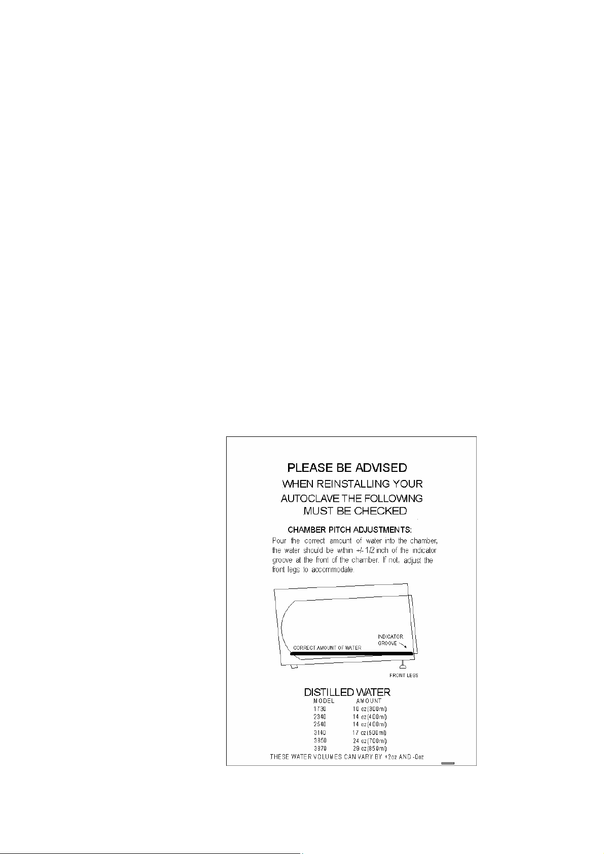
♦ Measure out the proper amount of distilled water for the appropriate
model unit as listed below:
1730 = 10 oz. (300ml)
2340 = 14 oz. (400ml)
2540 = 14 oz. (400ml)
3140 (3545) = 17 oz. (500ml)
3850 = 24 oz. (700ml)
3870 = 29 oz. (850ml)
All water volumes can be +2 oz and – 0 oz
♦ Pour the proper amount of water into the Chamber through the front
door of the unit.
♦ The water should cover the bottom of the Chamber to within +/- ½ inch
of the grove in the front.
♦ If necessary, adjust the front Leveling Feet so that the water lies in the
Chamber correctly.
♦ Once the Chamber pitch adjustment is completed, empty the water from
the Chamber and check if the automatic filling is set correctly.
11

Checking the Automatic Fill
To check the automatic filling procedure, follow the next few steps:
♦ Remove any water that is in the Chamber.
♦ Make sure the unit is turned on.
♦ With the Door open, press and hold
♦ Press the START Key.
♦ When water starts flowing into the Chamber, release the Door Switch.
♦ Water should come up to the same spot as the measured amount had.
♦ If the water fill is not working correctly, try the adjustment procedure or
check for a system problem [see sec. 7.15].
Automatic Filling Adjustment Procedure
♦ Make sure the power is off.
♦ The Door should be open.
♦ Press and hold
Keypad with the two arrows).
♦ Turn the power on.
♦ When the normal display screen appears, release the Water Inlet Key –
wait one second and then press it in again.
♦ Water should begin flowing into the Chamber.
♦ Monitor the water flow into the Chamber.
♦ Hold the Water Inlet Key until water reaches the groove at the front.
♦ Release the button – wait ten seconds – the unit is now reprogrammed
and ready to use.
the Water Inlet Key (this is the button on the front
the Door Switch.
12

2.4.2 Setup and Automatic Filling for Units With Water Pumps
Any unit with a Microprocessor Software version number ending in WP
[see sec. 8.12] will have a Water Pump installed to insure proper filling.
♦ Start with a sturdy, level counter.
♦ Make sure all the feet are on the autoclave and none have been lost.
♦ Make sure the front feet are free to move in and out.
♦ Position the autoclave on the counter.
♦ Fill the Reservoir with distilled water [see sec. 5.2].
♦ The Chamber should be empty of any instruments, trays or leftover
water.
♦ The unit is now ready to use.
To calibrate the automatic fill follow this procedure:
1. Press the STOP Key repeatedly until the message “Code: xxx” appears.
2. Using the UP/DN arrow keys change the code to 105 and press the
STOP Key.
3. A message will be displayed saying “Water in = xx sec.”
4. Using the UP/DN arrow keys, change the seconds according to the
following table:
2340/EZ9 = 30 sec
2540/EZ10/EZ10K = 35 sec
3140 = 40 sec
3850 = 45 sec
3870 = 65 sec
5. Press the STOP Key.
6. On some units the message “Ea Type:” may appear, using the UP/DN
arrow keys select either “0” for an E or EK type unit or “1” for an EA
or EKA type unit.
7. Press the STOP Key to finish.
13
3 Front Panel Keypad
3.1 Front Panel Keypad
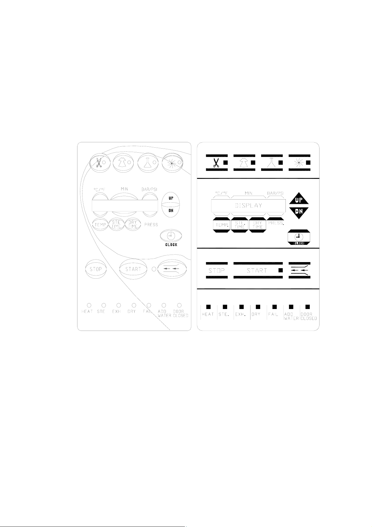
The Front Keypad is divided into four sections, top, upper middle, lower middle
and bottom. There are two keyboard types (see below):
New Type (blue) Old Type (gray)
The Top Section has four lighted buttons; these represent the four available
programs. Each program comes preset from the factory with default parameters.
Each program can, however, be modified by the operator. If necessary, the default
or modified parameters can be locked-in [see sec. 8.10]. When a program is
selected, the light in that button will illuminate and the program parameters will
appear in the display.
14

Moving from left to right the programs are:
Unwrapped Instruments – symbolized by a pair of scissors
The default parameters are:
273°F for temperature
3 minutes of sterilization time
Rapid exhaust
No drying time
Wrapped Instruments – symbolized by a gown
The default parameters are:
273°F for temperature
7 minutes of sterilization time
Rapid exhaust
30 minutes of drying time
Liquids/Glassware – symbolized by a flask
The default parameters are:
250 °F for temperature
30 minutes of sterilization time
Slow exhaust only
No dry time, drying is not allowed
Extra Drying Cycle – symbolized by the fan
The default parameter is:
30 minutes of drying time
The purpose of the Extra Drying Cycle is to offer an alternative in situations
where the dry time in the wrapped or unwrapped cycle is insufficient. Rather than
wait for the items to air dry or run another complete cycle with a longer dry time,
just select the Extra Drying Cycle to continue the heat assisted drying process.
The Upper Middle Section consists of a:
Display –
The Display is comprised of a single row of 16 characters and this row is divided
into four sections.
♦ When the system is running a program, the screen will display the current
temperature and pressure within the Chamber and the remaining time for
sterilization or drying.
♦ The first three sections from left to right are designed to show the parameters of
the selected program or any operating messages.
♦ When the system is idle, the display will show the parameters of the currently
selected program.
♦ When the system is running a program, the actual sterilization temperature is
displayed above the TEMP Key. The remaining sterilization time will be
displayed above the STE TIME key and the remaining drying time will be
displayed above the DRY TIME Key.
15

♦ If the program aborts as a result of a program check or manual stop, a message
will be displayed on the screen. When a message is displayed, pressing any key
will erase the message and redisplay the selected program.
♦ The last section of the screen, on the right, will continually display the actual
current real pressure inside the Chamber and this occurs whether a program is
running or not (provided the main power is on).
TEMP Key –
The TEMP Key is used to change the temperature parameter of the Wrapped,
Unwrapped or Liquids/Glassware programs. This can only be done while the
autoclave is not running a cycle. Press the TEMP Key and a cursor will appear
under the temperature parameter. Use the Up/Down Arrow Keys to change to the
desired temperature. After a few seconds of inactivity the cursor will disappear and
the parameter will be locked in. The acceptable range for proper sterilization of
wrapped and unwrapped items is between 250°F and 274°F (121°C and 134°C).
For liquids the maximum temperature is 250°F (121°C).
In addition, the TEMP Key can be used to change the temperature display from
Fahrenheit to Centigrade. This can be accomplished by simply turning the power
off, pressing and holding the TEMP Key and turning the power back on.
STE TIME –
The STE TIME Key is used to change the sterilization time parameter of the
Wrapped, Unwrapped or Liquids/Glassware programs. This can only be done
while the autoclave is not running a cycle. Press the STE TIME Key and a cursor
will appear under the sterilization time parameter. Use the Up/Down Arrow Keys
to change to the desired sterilization time. After a few seconds of inactivity the
cursor will disappear and the parameter will be locked in.
DRY TIME –
The DRY TIME Key is used to change the dry time parameter of the Wrapped,
Unwrapped and Extra Drying programs. This can only be done while the
autoclave is not running a cycle. Press the DRY TIME Key and a cursor will
appear under the dry time parameter. Use the Up/Down Arrow Keys to change to
the desired dry time. After a few seconds of inactivity the cursor will disappear and
the parameter will be locked in. The acceptable range for drying time is 0 to 99
minutes.
In addition, the DRY TIME Key can be used to change the pressure display from
psi to bar (on all machines up to and including Microprocessors dated T93N6) or
from psi to kpa (on all machines with Microprocessors dated T96DN1 or T97DN6
or later). This can be accomplished by simply turning the power off, pressing and
holding the DRY TIME Key and turning the power back on.
16

CLOCK Key –
Pressing the CLOCK Key once will display the current date with a cursor under
the day parameter. Pressing the Up/Down Arrow Keys will change the day
parameter. Pressing the CLOCK Key once again will move the cursor underneath
the month and the year parameters. Once the date has been updated, pressing the
CLOCK Key again will display the time with the cursor under the hour. Use the
Up/Down Arrow Keys as before to change the hours, run through the minutes and
seconds pressing the CLOCK Key each time to make the advance. After a few
seconds of inactivity the cursor will disappear and the parameters will be locked in.
UP / DOWN Arrow Keys
Pressing these keys will raise or lower the values on any of the parameters that are
user adjustable.
The Lower Middle Section consists of a:
STOP Key –
This is the only key recognized by the system while a cycle is running. Pressing
the STOP Key for over one second will cause the current program to abort and the
MAN STOP message to be displayed.
In addition, the STOP Key can be used to reset all the parameters back to their
factory defaults. This includes the Automatic Fill, in which case it will be
necessary to recalibrate the Automatic Fill.
♦ Turn the power off
♦ Press and hold the STOP Key
♦ Turn the power on
START Key –
Pressing this key will start whichever program cycle has been selected and cause
the START Key light to turn on.
Water Inlet Key–
This key is symbolized by the two horizontal arrows pointing in through a channel.
Pressing and holding this key allows for the manual filling of the Chamber with
water. This is useful for calibrating the Automatic Fill, also during cleaning to
flush out the Chamber and in case it becomes necessary to bypass the Automatic
Fill before running a cycle. Water will flow into the Chamber only as long as the
key is depressed.
17

The Bottom Section consists only of indicator lights. Looking from left to right
they are the:
HEAT Light –
A steady illumination is given when the autoclave is heating up at the beginning of
the cycle.
Also, this light will flash during the preheat/standby mode on units in which that
option has been activated (all EK, EKA, EZ10K, 3850 and 3870 machines).
STE Light –
A steady illumination is given while the autoclave is in the sterilization portion of
the cycle.
EXH Light –
A steady illumination is given when the autoclave is exhausting the Chamber.
DRY Light –
A steady illumination is given while the autoclave is in the Drying mode.
CYCLE FAIL Light –
Will illuminate anytime the autoclave detects a problem that results in an aborted
cycle.
ADD WATER Light –
This indicator will light when the Reservoir is low on water. If the indicator lights,
after the Start Key has been pressed, the system will continue with the cycle.
There is sufficient water in the reservoir to complete this cycle. The next cycle will
not be allowed to begin until sufficient water is in the reservoir.
DOOR CLOSED Light –
This indicator lights to signal that the Door of the autoclave has been closed.
18

4 Display Messages
4.1 Display Messages
Anytime
These messages are in the form of words that describe the problem the unit has
encountered.
The following is a list of those Error Messages with descriptions of what they
mean and indications where the problem may be:
LOW WATER This message will be displayed, if during a normal Heat Up
stage, the system determines that there is insufficient water in
the Chamber to complete the cycle. This determination is
made by the combined input of two sensors, the Water
Electrode and the Temperature Safety Thermostat.
Also,
stage after
in order to resume the cycle. If not,
Fail indicator will light.
Possible causes for this message are:
LOW HEAT This message is displayed, the Cycle Fail indicator lights
and the cycle is aborted, if the autoclave has not reached
sterilization temperature after heating for 50 minutes in
either Wrapped or Unwrapped programs (80 minutes in the
Liquid program).
Low Heat refers to the temperature in the Chamber before
sterilization has begun.
a cycle is aborted, the Tuttnauer autoclave will give an error message.
if a power failure occurs during the Heat or Sterilization
the power returns, the system will check the Water
Electrode to see if there is sufficient water in the Chamber
the cycle will be aborted,
the message LOW WATER will be displayed, and the Cycle
a. Insufficient water entered the Chamber at the beginning of
the cycle.
Check for proper leveling, a dirty or shorted Water
Sensing Electrode, a clogged Water Pump, a partially
clogged line or that the Air Outlet Valve is stuck closed.
b. A leaky Solenoid Valve, Safety Valve, Air Jet, Door
Gasket, Door Bellows or a pipe fitting is allowing water or
steam to escape at a higher than normal rate.
c. A power down has occurred and on power up, if the water
Electrode tip is dry the Low Water message will be
displayed.
19

Possible causes for this message are:
a. No power to the Heating Elements.
b. Bad Heating Elements.
c. Very low line voltage delaying heat up.
d. Temperature Safety Thermostat is opening prematurely,
turning off the Heating Elements. This only applies to
units with Microprocessors dated earlier than T93N5 or
T93N6.
e. A clogged Air Jet.
f. An Air Outlet Valve stuck closed.
LOW TEMP This message is displayed if the Cycle Fail indicator lights,
the cycle is aborted and the temperature drops 4.5
o
F (2.5oC)
below the required sterilization temperature.
Possible causes for this message are:
a. Insufficient water in the Chamber (see Low Water
message).
b. The sterilization phase of the cycle has been set for too
long a period of time, allowing the Chamber water to boil
away and the Chamber to run dry.
c. The Temperature Safety Thermostat is opening
prematurely, turning off the Heating Elements -- this only
applies to units with Microprocessors dated earlier than
T93N5 or T93N6.
d. A bad Temperature Sensor.
LOW PRES This message is displayed, the Cycle Fail indicator lights, and
the cycle is aborted if the pressure drops 4 PSI (0.27 BAR)
below the required sterilization pressure.
Possible causes for this message are:
a. Insufficient water in the Chamber (see Low Water
message).
b. The
Heating Elements are not cycling on and off properly.
1. Problem is with the Solid State Relay.
2. Problem with the control circuit.
c. Bad
Heating Elements -- not producing enough wattage.
d. The Temperature Safety Thermostat is opening
prematurely, turning off
the Heating Elements -- this only
applies to units with Microprocessors dated earlier than
T93N5 or T93N6.
e. A bad Pressure Transducer.
20

HIGH TEMP This message is displayed, the Cycle Fail indicator lights and
the cycle is aborted if the temperature rises 9oF (5oC) above
the required sterilization temperature during the Sterilization
phase of the cycle.
This message will also be displayed if the Temperature
Sensor is damaged. In this case, the message will appear just
before the Heat phase starts.
Possible causes for this message are:
a. The Heating Elements are remaining on instead of cycling
on and off.
Check for a shorted Solid State Relay, shorted Heating
Element or other short circuit.
b. This message can ALSO indicate a bad Temperature
Sensor -- the message will display anytime during the Heat
Up phase.
HIGH PRES This message is displayed, the Cycle Fail indicator lights, and
the cycle is aborted if the pressure rises 10 PSI (0.6 BAR)
above the required sterilization pressure.
Possible causes for this message are:
a. The Heating Elements are remaining on instead of cycling
on and off.
Check for a shorted Solid State Relay, shorted Heating
Element or other short circuit.
b. The
Sterilization temperature has been set above 274°F.
MAN STOP This message will be displayed and the Cycle Fail indicator
will light after the STOP Key is depressed for longer than
1 second.
RENEW WATER This message is displayed only as information to the operator
that the Water Reservoir should be drained and refilled with
clean distilled water. This message will only appear on units
with Microprocessors having software version numbers earlier
than and including T93N5.
POWER DN This message is displayed, once the power is restored, after a
power failure occurs during the running of a cycle. The
POWER DN message will be displayed for several seconds,
and if present, the Printer will print POWER DN on the print
out.
Once power has been restored the autoclave will make an
attempt to resume the current cycle from the point at which
it was interrupted.
21

♦ If a power failure occurs during the Heat Up phase,
heating will resume (provided there is enough water in the
Chamber. If not, the cycle will be aborted).
♦ Exhaust and Dry phases will automatically resume
operation once power is restored.
♦ If the power down occurred during the Sterilization
portion of the cycle, when power is restored, the autoclave
will check if the temperature in the Chamber has fallen
more than 4.5°F (2.5°C). If not, the Sterilization Cycle will
resume automatically. If, however, when the power returns
and the system determined that the temperature has fallen
more than 4.5°F (2.5°C), the Sterilization Cycle will abort
and the Exhaust Cycle will start.
♦ If a power failure occurs during the Liquids program, the
system will not
allow a fast exhaust (as the exhaust valve
is normally closed), nor will it fast exhaust when power
comes back on.
ADD WATER This message is displayed and the ADD WATER indicator
lights to show insufficient water in the Water Reservoir. If
this message is displayed after the START Key has been
pressed
is
, the system is not allowed to proceed. After water
added to the Reservoir, the START Key must be depressed
again in order for the selected cycle to begin.
DOOR UNLOCK This message will be displayed and the DOOR CLOSED
indicator will remain unlit if the door is improperly closed
when
the START Key is depressed. Once the door is properly
closed, the DOOR CLOSED indicator will light and the
START Key should be depressed to start the desired cycle. If
the door becomes ajar during any stage of the cycle, the
same message and indicator will appear, and the system will
abort, the Cycle Fail indicator will light and the DOOR
UNLOCK message will be displayed.
WATER INLET This message will be displayed as information to the operator
while water is entering the Chamber, during the Automatic
Water Filling process.
CYC FINISHED This message is displayed at the end of a successfully
completed cycle.
22

5 Operating Instructions
5.1 Preparation Before Sterilizing
Note: These instructions are provided as a minimum
Instruments to be sterilized must be free from all residual matter, such as blood or
organic tissue. Instruments must also be dry and free from mineral deposits. Such
substances may cause damage to the instruments themselves or the Sterilizer.
1. Clean instruments immediately after use to remove any residue. It is
recommended that all instruments be ultrasonically cleaned using Tuttnauer's
CLEAN AND SIMPLE enzymatic cleaning tablets or other suitable
solution.
2. After cleaning, rinse instruments for 30 seconds and pat or air dry.
3. Follow the instrument manufacturer’s instructions on the use of products for
cleaning and lubricating instruments that have been ultrasonically cleaned.
4. Be sure that instruments of dissimilar metals (stainless steel, carbon steel,
etc.) are separated. Carbon steel instruments should be bagged or placed on
autoclavable towels and not directly on stainless steel trays.
5. When using a paper/plastic bag, the plastic side should always be down.
6. Check the instructions of the item manufacturer as to the proper procedure
for sterilizing each item.
7. Items must be sterilized in an open position. Surfaces that are hidden because
the item is in a closed position will not be exposed to the steam and will not
be sterilized.
8. Place a sterilization indicator in each tray or inside each wrapped pack.
9. At least once a week use a biological spore test (Bacillus Stearothermophilus)
in any load to insure proper sterilization, (be aware testing standards may
vary). Always follow the spore test manufacturer’s instructions.
10. Make sure that all instruments remain apart during the sterilization cycle.
Surfaces that are hidden because items are covering other items will not be
exposed to the steam and will not be sterilized.
11. Empty canisters should be placed upside-down in order to prevent the
accumulation of water.
guideline.
23

12. Do not overload the Sterilizer trays. Overloading will cause inadequate
sterilization and drying (see table 9.7 for loading limits for each model).
13. Allow a distance of approximately 1" between trays to permit steam
circulation.
14. Wrapped instruments should be placed in material, which will allow steam
penetration and promote drying, such as an autoclave bag, autoclave paper, or
muslin towels.
15. Do not stack pouches. It is recommended that a pouch rack, such as the
Tuttnauer Pouch Rack, be used to insure proper steam penetration and
adequate drying. Surfaces that are hidden because the items are being stacked
will not be exposed to the steam and will not be sterilized.
16. Tubing should be rinsed after cleaning. When placed in the tray, make sure
that both ends of the tubing are open and there are no sharp bends or twists.
17. Packs should be placed upright on the tray. They should not be touching
each other or the Chamber walls. There should be about 1” between packs
for proper steam circulation.
18. Liquids should only be sterilized in heatproof glass. The beaker should only
be filled 2/3 full and the lid should be on loosely to allow for expansion (see
the table 9.9 for the maximum liquid capacity for each model).
19. If spotting were detected on the instruments, the first step would be to use an
ordinary eraser to remove the spot. If there is no pitting under the spot, the
spot was only dirt. Dirt spots on an instrument may be an indication that the
autoclave needs to be cleaned or that the instruments were not adequately
cleaned or dried. If removal of the spot reveals pitting, the spot was most
likely rust. Rust spots on an instrument are not uncommon on inexpensive
instruments. It may also be an indication that the instruments were rinsed in
tap water with a high content of minerals. These minerals when exposed to
high temperature and steam will accelerate the oxidation of the metal. One
suggestion would be to final rinse the instruments in distilled water.
20. If the instruments exhibit a discoloration, this can be due to the mixing of
carbon steel and stainless steel. When these two metals come into contact
with each other, electrolysis occurs that breaks down the metal. The best
solution is to separately wrap the carbon steel to insulate it from other
instruments or the trays.
21. Items should not be allowed to touch the walls of the Chamber as the hot
metal can damage the item.
24
5.2 Filling The Reservoir
Always use DISTILLED WATER in the autoclave for sterilizing. Using water of
a poorer quality will cause increased maintenance due to the mineral residue that
accumulates in the various parts of the autoclave.
The Reservoir is filled from the top of the autoclave. Remove the Reservoir Cover
and pour water through the opening. Continue filling until the water reaches the
base of the Safety Valve Holder. Under no circumstances should the Reservoir
be filled above the Safety Valve Holder. The Reservoir should never be filled
while the autoclave is running a cycle. If the Reservoir is filled while the
Autoclave is running, at the end of the cycle, water exhausted from the Chamber
can cause the Reservoir to overflow.
Overfilling or the failure to use Distilled Water will lead to clogging of the hole in
the Air Jet. This will be evidenced by the lack of both a hissing sound and a stream
of steam coming from the Air Jet during sterilization. When this situation occurs,
follow the instructions in sec. 6.5 for cleaning the Air Jet.
25

5.3 Sterilization Programs
Program 1 – Unwrapped Instruments
This program is for sterilizing unwrapped instruments and materials, that
the manufacturer of these items has recommended autoclaving, at a
temperature between 250°F and 274°F (121°C and 134°C).
This program comes set with these default parameters:
Sterilization temperature 273°F
Sterilization time 3 minutes
Dry time none
These values can be altered to fit the needs of a particular office.
The parameters can only be changed while the autoclave is not running a
cycle.
Press the TEMP Key and a cursor will appear under the temperature
parameter. Use the Up/Down Arrow Keys to change to the desired
temperature. The acceptable range for proper sterilization of unwrapped
items is between 250°F and 274°F (121°C and 134°C).
*** Caution – in no case should the temperature be set higher than
274
°F (134°C) ***
Any change of temperature must be coordinated with a corresponding
change in sterilization time.
Press the STE TIME Key and a cursor will appear under the sterilization
time parameter. Use the Up/Down Arrow Keys to change to the desired
sterilization time.
If drying is desired, press the DRY TIME Key and a cursor will appear
under the dry time parameter. Use the Up/Down Arrow Keys to change to
the desired dry time. The acceptable range for drying time is 0 to 99
minutes.
After a few seconds of inactivity the cursor will disappear and the
parameter will be locked in.
26

Program 2 – Wrapped Instruments
This program is for sterilizing wrapped instruments and materials, that the
manufacturer of these items has recommended autoclaving, at a
temperature between 250°F and 274°F (121°C and 134°C).
This program comes set with these default parameters:
Sterilization temperature 273°F
Sterilization time 7 minutes
Dry time 30 minutes
These values can be altered to fit the needs of a particular office.
The parameters can only be changed while the autoclave is not running a
cycle.
Press the TEMP Key and a cursor will appear under the temperature
parameter. Use the Up/Down Arrow Keys to change to the desired
temperature. The acceptable range for proper sterilization of unwrapped
items is between 250°F and 274°F (121°C and 134°C).
*** Caution – in no case should the temperature be set higher than
Any change of temperature must be coordinated with a corresponding
change in sterilization time.
Press the STE TIME Key and a cursor will appear under the sterilization
time parameter. Use the Up/Down Arrow Keys to change to the desired
sterilization time.
If a longer or shorter drying is desired, press the DRY TIME Key and a
cursor will appear under the dry time parameter. Use the Up/Down Arrow
Keys to change to the desired dry time. The acceptable range for drying
time is 0 to 99 minutes.
After a few seconds of inactivity, the cursor will disappear and the
parameter will be locked in.
274
°F (134°C) ***
27
 Loading...