

Page 1

OPERATI ON
&
MAI NTENANCE
MANUAL
Pre-vacuum Steam Sterilizer with
Generator
Models ELARA9-D, ELARA11-D
Cat. No. MAN205-0497001ENRev A
Tuttnauer Europe b.v., Hoeksteen 11, 4815 PR, Breda, P.O. Box 7191, 4800 GD Breda,
Netherlands.
+31/76-5423510, Fax: +31/76-5423540
Page 2

Page 3

Page 1
TABLE OF CONTENTS
PARAGRAPH PAGE NO.
1. GENERAL...................................................................................................................................3
1.1. INTRODUCTION ................................................................................................ ..........................3
1.2. INCOMING INSPECTION................................................................................................................ 3
1.3. WARRANTY DESCRIPTION.............................................................................................................4
1.4. WARRANTY STATEMENT .............................................................................................................. 4
1.5. SAFETY .....................................................................................................................................4
1.6. SPECIFICATIONS................................................................ .......................................................... 5
1.7. GENERATOR STEAM DATA............................................................................................................ 9
1.8. AUTOCLAVE ELECTRICAL DATA ...................................................................................................... 9
1.9. UTILITIES .................................................................................................................................. 9
1.10. ENVIRONMENTAL EMISSION INFORMATION ................................................................................... 10
1.11. CONSTRUCTION........................................................................................................................10
1.12. STICKERS DESCRIPTION .............................................................................................................. 10
1.13. WATER QUALITY ...................................................................................................................... 10
1.14. DIRECTIVES AND STANDARDS................................ ...................................................................... 11
2. CONTROL PANEL ..................................................................................................................... 12
2.1. KEYPAD ..................................................................................................................................13
2.2. PRINTER ................................................................................................................................. 14
2.3. PRINTER HANDLING .................................................................................................................. 14
2.4. DISPLAYED ERROR MESSAGES / SYMBOLS ..................................................................................... 16
2.5. DISPLAYED OPERATIONAL MESSAGES / SYMBOLS............................................................................16
3. STERILIZATION PROGRAMS ..................................................................................................... 17
3.1. STERILIZATION CYCLE DESCRIPTION .............................................................................................. 17
3.2. VACUUM TEST PROCESS DESCRIPTION.......................................................................................... 18
3.3. BOWIE AND DICK TEST PROCESS DESCRIPTION ............................................................................... 18
4. INSTALLATION INSTRUCTION .................................................................................................. 18
4.1. LIFTING AND CARRYING ................................................................ ............................................. 18
4.2. INSTALLATION PREPARATIONS..................................................................................................... 19
5. PREPARATION BEFORE STERILIZATION. LOADI NG .................................................................. 20
5.1. GENERAL RULES TO BE CONSIDERED:............................................................................................20
6. OPERATING INSTRUCTIONS..................................................................................................... 23
6.1. FILLING THE MINERAL-FREE WATER RESERVOIR. ............................................................................ 23
6.2. TURNING ON THE AUTOCLAVE.....................................................................................................24
6.3. WASTE WATER LEVEL ............................................................................................................... 24
6.4. HEATING................................................................................................ ................................. 24
6.5. OPENING THE DOOR ................................................................................................ .................24
6.6. STARTING A CYCLE .................................................................................................................... 25
6.7. ENDING THE CYCLE. UNLOADING................................................................ ................................. 25
6.8. STOPPING THE PROCESS MANUALLY................................................................ ..............................26
6.9. STOPPING THE PROCESS DUE TO CYCLE FAILURE.............................................................................. 26
7. CHECKING AND CHANGING PARAMETERS AND OTH ER DATA ................................................. 26
7.1. QUICK OPTIONS SCREEN ............................................................................................................ 26
7.2. ENTERING THE MAIN MENU....................................................................................................... 27
7.3. SYSTEM PARAMETERS................................................................................................................ 27
7.4. MAINTENANCE ........................................................................................................................ 27
8. MAINTENANCE INSTRUCTIONS ...............................................................................................28
8.1. PREVENTIVE AND SCHEDULED MAINTENANCE ................................................................................ 28
8.2. CLEAN THE OUTER PARTS OF THE AUTOCLAVE WITH A SOFT CLOTH. ..................................................... 28
Page 4

Page 2
8.3. DRAINING THE RESERVOIR................................................................ .......................................... 29
8.4. CLEANING THE WATER OUTLET STRAINER....................................................................................... 30
8.5. REPLACING THE HEPA AIR FILTER ............................................................................................... 30
9. TROUBLESHOOTING ................................................................................................................ 31
10. SPARE PARTS LIST ................................................................................................................... 34
11. ACCESSORIES........................................................................................................................... 34
Page 5

Page 3
1. GENERAL
1.1. Introduction
The ELARA autoclave is designed for sterilization of wrapped and unwrapped instruments,
and related items found in dental, medical, and veterinary clinics, first aid rooms, hospitals,
laboratories etc. The autoclave offers a choice of automatic programs designed to match the
material to be sterilized. Drying is performed with the door closed.
This autoclave model is a steam-heated sterilizer using steam as a sterilizing agent. A
computerized control unit ensures a fully automatic sterilization cycle, control and monitoring
of physical parameters and a clear documentation of the sterilization cycle.
This autoclave is equipped with a vacuum system. The advantages of the prevacuum
sterilizer in comparison to the regular gravity displacement steam sterilizer are as follows:
• Removal of air pockets from packs and porous load and most kinds of tubes (rubber,
plastic etc.) by vacuum at the first stage of the cycle.
• Better steam penetration into the load; resulting in effective sterilization.
• Better temperature uniformity.
• A post sterilization drying phase based on the combined operation of heat and
vacuum with air inlet pulses.
A digital display is used for monitoring and control purposes. The device is capable of
displaying the pressure in psia, psig, or in kPa according to the operator’s requirements.
When the pressure is displayed in psig, the atmospheric pressure is shown (at sea level) as 0
psig. If the pressure is defined in psia or kPa the absolute zero is displayed as “0” and the
atmospheric pressure is shown (at sea level) as 14.7 psia or 100 kPa respectively. The Elara
can display temperature in ºF or ºC.
A printer is a standard addition to the autoclave. The printer prints the preset and actual
parameters of the cycle (temperature, time and pressure).
The ELARA9-D/ELARA11-D features built in memory to record up to 100 sterilization cycles.
These can be reprinted on the printer or exported to a USB device to be transferred to a PC.
The ELARA9-D/ELARA11-D has a built in Network Port for use with Tuttnauer’s R.PC.R
software when connected to your local network.
The autoclave is available in following configurations:
• Standard (U): Waste water goes to the waste water reservoir. Excess of waste water
is drained through the hole in the bottom of the autoclave.
• W: Waste water is piped directly into the drain.
• WW: Direct inlet of demineralized water from plumbing. A sensor detects lack of water
in the reservoir to open the direct inlet valve.
Read the Operating Instructions carefully, before beginning any operation on the
autoclave!
1.2. Incoming Inspection
Upon receiving your Tuttnauer Autoclave, carefully inspect the outside of the shipping carton
for signs of damage. If any damage to the carton is found, note the location with respect to
the autoclave and check that area of the autoclave carefully once it is fully unpacked.
Observe packing method and retain packing materials until the unit has been inspected.
Mechanical inspection involves checking for signs of physical damage such as: scratched
panel surfaces, broken knobs, etc.
If any damage is found, contact your dealer as soon as possible so that they can file a
claim with the shipping carrier and also notify Tuttnauer.
All Tuttnauer products are carefully inspected prior to shipment and all reasonable
precautions are taken in preparing them for shipment to assure safe arrival at their
destination.
Caution!
Lifting and carrying should always be done by two people.
Page 6

Page 4
1.3. Warranty Description
This warranty does not include routine cleaning and preventive maintenance, to be
performed according to instructions in section 8.1
Tuttnauer warrantees all new ELARA9-D/ELARA11-D autoclaves to be free from defects in
material and workmanship for a period of one full year, covering the parts (except door
gaskets and HEPA filters – they are considered wear items).
Tuttnauer warrantees all chambers for a period of ten (10) years against defects in materials
and workmanship. This chamber warranty went into effect January 1997.
This warranty does not apply to any instrument that has been subjected to misuse, neglect,
accident or improper installation or application, nor shall it extend to autoclaves that have
been repaired or altered outside the factory without prior authorization from Tuttnauer.
Tuttnauer’s obligation is limited to the repair or replacement of parts for the autoclave. This
warranty will be void if the unit is not purchased from an authorized Tuttnauer dealer. No
other warranties or obligations are expressed or implied.
The Autoclave should only be used in a manner described in this manual!
1.4. Warranty Statement
The warranty registration must be completed and returned to our service departments; within
fourteen (14) days of purchase or the warranty will be void.
Our European Representative’s Technical Service Department can be reached at:
Tuttnauer Europe B.V., Hoeksteen 11 4815 PR P.O. Box 7191 4800 GD Breda, The
Netherlands
Tel: 31 (0) 765423510, Fax: 31 (0) 765423540, Email: info@tuttnauer.nl
Note: If there is any difficulty with this instrument, and the solution is not covered in this
manual, contact our representative or us first. Do not attempt to service this instrument
yourself. Describe the difficulty as clearly as possible so we may be able to diagnose the
problem and provide a prompt solution.
Send along a copy of the last printout for our inspection. If replacement parts are needed,
stipulate the model and serial number of the machine.
No autoclaves will be accepted for repair without proper authorization from us. All
transportation charges must be paid both ways by the owner.
1.5. Safety
Never use the autoclave to sterilize corrosive products (acids, bases, or phenols) volatile
compounds or solutions (ethanol, methano,l or chloroform), or radioactive substances.
Safety features
The pressure vessel chamber door has the following features protecting personnel from
hazards:
• Two door switches that indicate that the door is closed and locked. Without this
indication steam is not introduced into the chamber.
• An electrical door locking pin that blocks door opening during operation.
There are the following safety devices installed in the autoclave to optimize its safe operation:
• Two safety thermostats, to prevent over-heating of the steam generator and the
chamber.
• Two safety pressure valves to prevent over-pressurizing the steam generator or the
chamber.
Safety Instructions
• All new autoclave users must receive must undergo a period of training in proper
usage under an experienced employee.
• Before use, check inside the autoclave chamber to ensure that no items have been
left from the previous cycle.
• Load trays in such a way as to allow steam to move freely among all items.
• When sterilizing plastic materials, make sure that the item can withstand sterilization
temperature. Plastic that melts in the chamber is liable to cause a great deal of
damage.
Page 7
Page 5
• On closing the device door, make sure it is properly locked before activating. Verify
that DOOR OPEN
symbol is replaced by the message "System Ready".
• Verify once again that you have chosen the appropriate sterilization program.
• Open the door slowly to allow steam to escape and wait 1 minute before you remove
the load.
• When removing the trays it is recommended to use the tray handle or wear heat
resistant gloves.
• A certified inspector must perform a periodic pressure chamber safety test according
to the local regulations.
• Once a year, or more frequently, effectiveness tests must be performed, i.e.,
calibration and validation.
• Make sure there are no leaks, breaks, blockages, whistles or strange noises.
• Perform maintenance operations as instructed. The owner of the autoclave is
responsible to perform the maintenance operations.
• Notify the person in charge immediately of any deviation from the normal functioning
of the device.
• Protective equipment and clothes and other safety instructions should be
implemented in accordance with local and national regulations and/or rules!
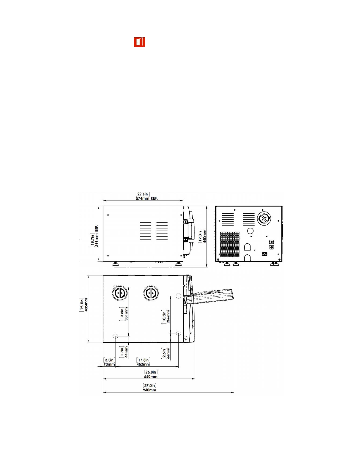
1.6. Specifications
Overall Dimensions: ELARA 9-D
Page 8
Page 6
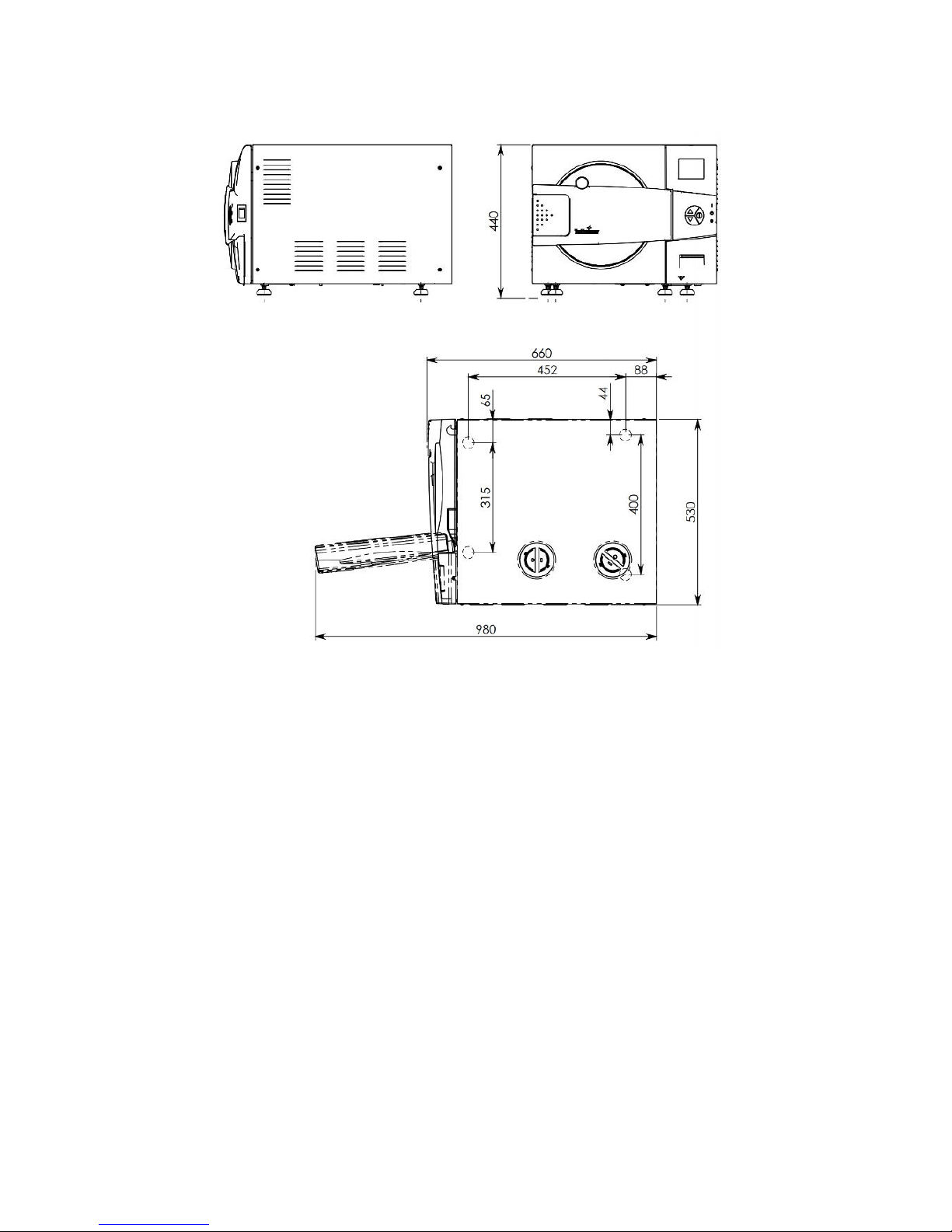
Overall Dimensions: ELARA 11-D
Page 9
Page 7
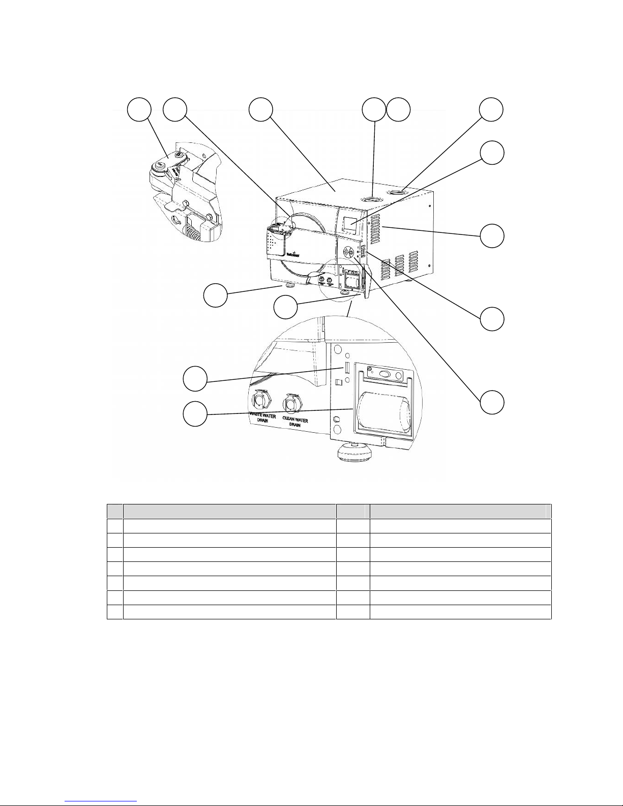
Front View
No.
Description
No.
Description
1
Door switches
8
Ventilation grill
2
Autoclave door
9
On/ off switch / circuit breaker
3
Autoclave cover
10
Keypad
4
Mineral-free water reservoir cover
11
Printer cover
5
Chamber and steam generator safety valves
12
Autoclave Leg
6
Waste water reservoir cover
13
USB connection
7
Display
14
Printer
54689
10
11
121237
14
13
Page 10
Page 8
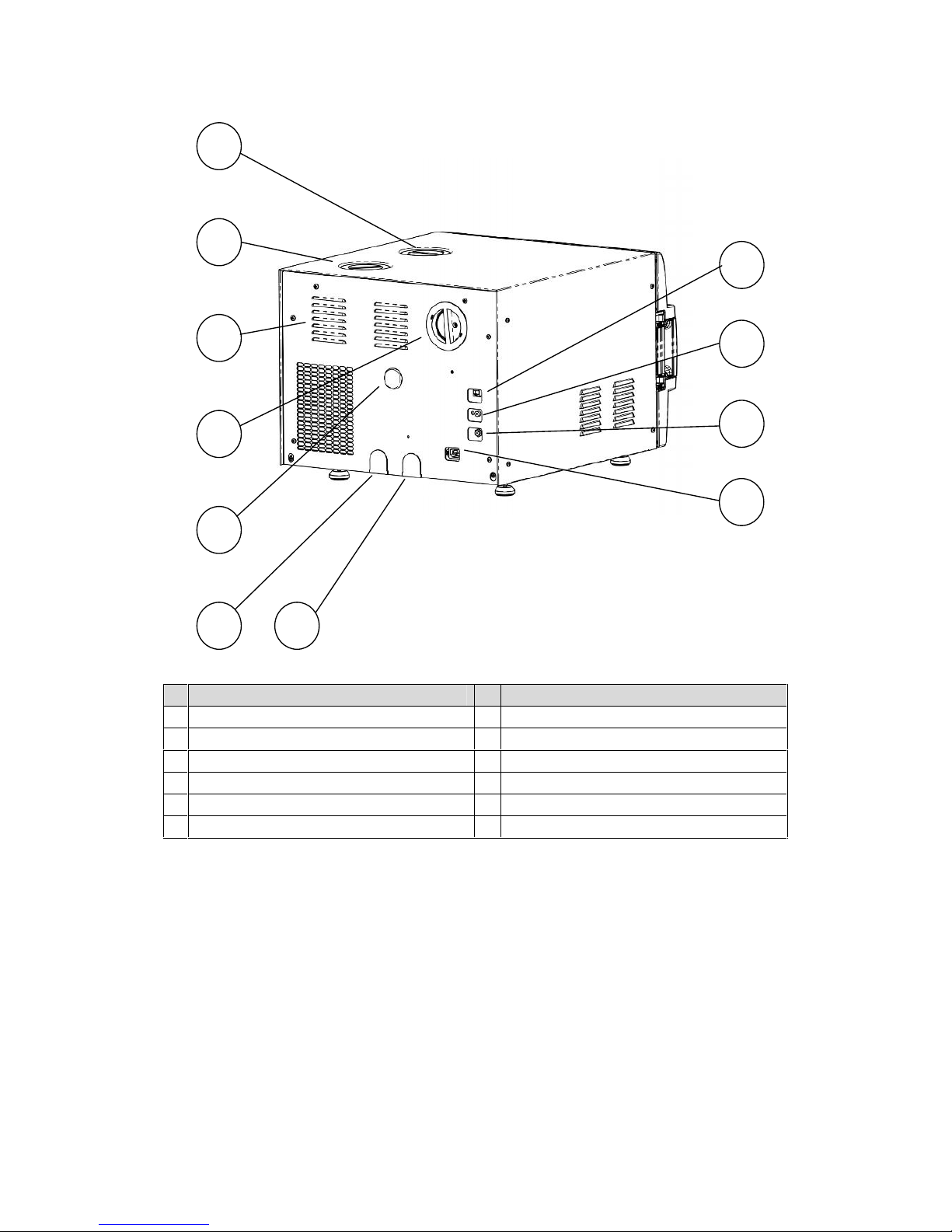
Rear View
No.
Description
No.
Description
1
Mineral-free water reservoir cover
7
Automatic water filling inlet (optional)
2
Waste water reservoir cover
8
RJ45 network connector
3
Ventilation grills
9
Chamber cut-off
4
Air filter service cover
10
Chamber cut-off
5
Opening for calibration
11
Main power electric cable socket
6
Overflow outlet to drain
54812
3
6
7
9
10
11
Page 11
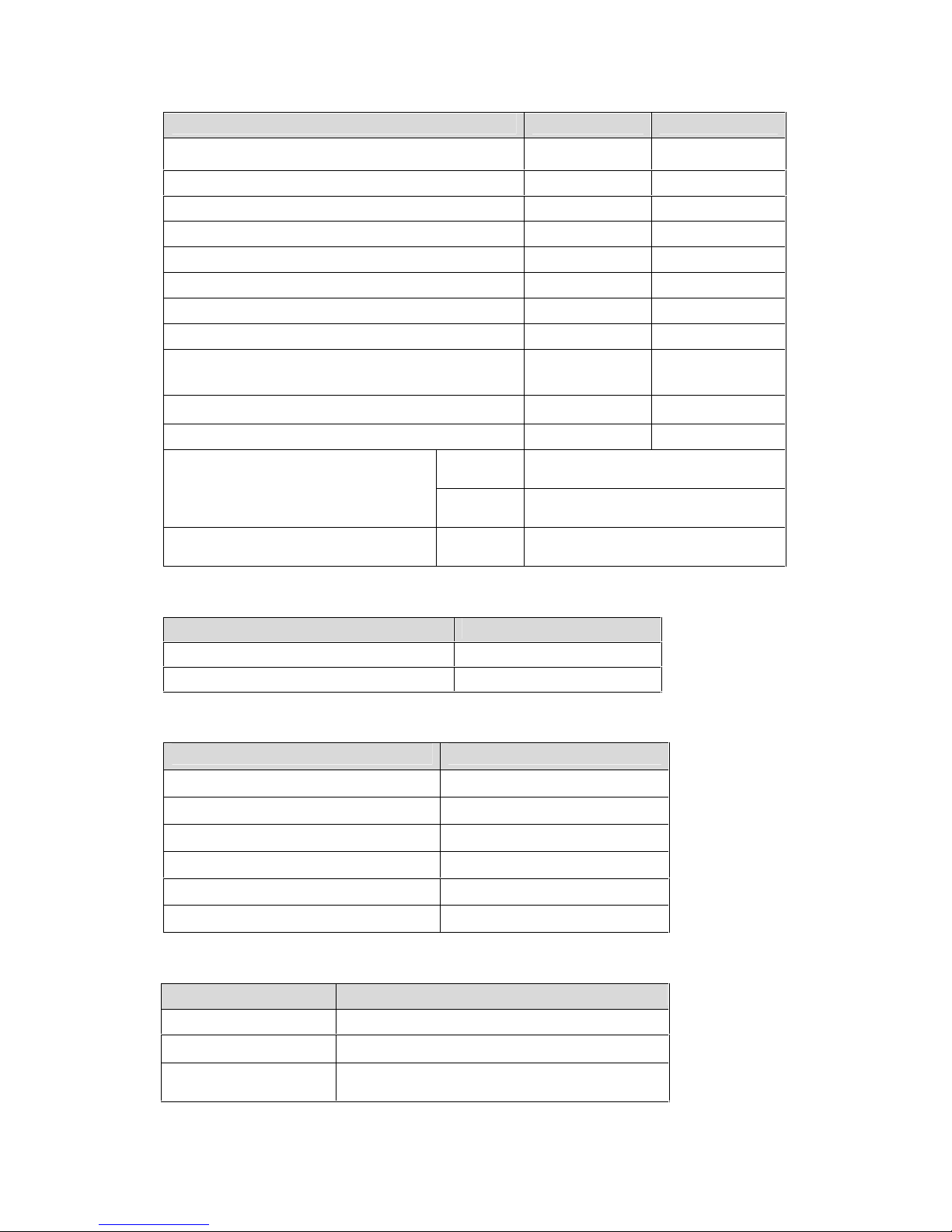
Page 9
Property
ELARA9-D
ELARA11-D
Chamber Diameter
230 mm
280 mm
Chamber Depth
504 mm
504 mm
Chamber volume
19 lit
28 lit. (7.4 gal)
Max. Allowable Working Pressure (MAWP)
2.8 bar
Maximum load per item
0.3kg
0.3kg
Maximum load per tray
1.5
1.5kg
Maximum solid load
5.0kg
8.0kg
Maximum textile load
1.5kg
2.0kg
Tray dimensions
17 x 41.5 x 2.1
cm
17 x 41.5 x 2.1
cm
No. of trays
3
5
Weight
62.15
71.7kg
Mineral-free water reservoir
Max. water
volume
6.6lit
Min. water
volume
2.6lit.
Used (waste) water reservoir
Max. water
volume
5.2lit.
1.7. Generator Steam Data
Property
Value
Max. working pressure
3 BarG
Safety relief valve
5 Bar
1.8. Autoclave Electrical Data
Property
Value
Total Power
2500W
Voltage
1 ph / 230 VAC
Amperage
11A
Protection against electrical shock
Class I (IEC 60601-1)
Mains supply fluctuation
+/- 10%
Frequency (Hz)
50Hz
1.9. Utilities
Property
Value
Mineral free water
See table in 1.13
Power supply
* 1 phase, /230VAC ±10%, 50Hz
Recommended circuit
breaker
16A
* According to the local network.
Page 12

Page 10
Cautions!
In order to avoid any injury by electrical hazard, it is recommended that
a ground fault protection device (GFCI) be installed in the electrical
panel feeding the autoclave (local codes may make this mandatory).
The electrical network must comply with local rules or regulations.
Verify that there is an easy access to the main power switch and to the
current leakage safety relay (GFCI). The voltage supplied to the device
must comply with the label ± 5%.
Note: The electrical network must comply with local rules or regulations.
Verify that there is an easy access to the main power switch and to the current leakage
safety relay (GFCI). The voltage supplied to the device must comply with the label ± 5%.
1.10. Environmental Emission Information
• The peak sound level generated by the autoclave is 65dBa with background
noise of 48 dBa.
• The total heat per hour transmitted by the autoclave is <200Wh.
1.11. Construction
The main parts of the autoclave are made of materials as indicated below:
• Chamber is built of stainless steel 316 L.
• Door is made of stainless steel 316.
• Trays are made of stainless steel 304.
• Water reservoir is made of polyethylene.
• Door handle and door cover are made of hard plastic material, which is safe to touch
and thermo-insulated.
1.12. Stickers Description
Symbol
Meaning
Part Number
Location
Caution! Consult
accompanying
documents
LAB048-0024
Near the main power electric
cable socket, and on the
front door upper-left corner
Caution! Hot steam.
LAB048-0058
On the top cover near the
water reservoirs opening (hot
steam emerges out of the
safety valve located inside
the reservoirs)
1.13. Water Quality
Physical characteristics and contaminants levels
The distilled or mineral-free water supplied to the autoclave should have the physical
characteristics and maximum acceptable level of contaminants indicated in the table below:
Physical Characteristics and Maximum acceptable contaminants
levels in steam for sterlizers
(According to EN 13060:2004).
Element
Condensate – allowable
content
Silicium oxide. SIO
2
≤0.1 mg/kg
Iron
≤0.1 mg/kg
Cadmium
≤0.005 mg/kg
Lead
≤ 0.05 mg/kg
Page 13

Page 11
Rest of metals except iron,
cadmium, lead
≤0.1 mg/kg
Chloride (Cl)
≤0.1 mg/kg
Phosphate (P2O5)
≤0.1 mg/kg
Conductivity (at 20°C)
≤3
μ s/cm
pH value (degree of acidity)
5 to 7
Appearance
Colourless clean without
sediment
Hardness (Σ Ions of alkaline earth)
≤0.02 mmol/l
Compliance with the above data should be tested in accordance with
acknowledged analytical methods, by an authorized laboratory.
Note:
We recommend testing the water quality once a month. The use of water for autoclaves that
does not comply with the table above may have severe impact on the working life of the
sterilizer and can invalidate the manufacturer’s guarantee.
1.14. Directives and Standards
Every autoclave meets the provisions of the following Directives and is in compliance with the
following Standards:
Technical Directives
• Medical Device Directive 93/42/EEC.
• Pressure Equipment Directive 97/23/EEC.
Technical Standards
• EN 13060:2010 ― Small Steam Sterilizers.
• EN 61326 ― Electrical equipment for measurement, control and laboratory use-EMC
requirements
• IEC/EN 61010A-1 ― electrical equipment for laboratory use; general requirements
• IEC/EN 61010A-2-040 ― particular requirements for sterilizers and washer
disinfectors used to treat medical materials.
Quality standards
The manufacturing plant meets the following quality standards:
• EN ISO 9001:2008 – Quality System.
• ISO 13485:2003 – Quality systems – Medical devices.
• The manufacturer retains all supporting documentation.
Page 14

Page 12
2. CONTROL PANEL
No.
Description
1
Display
2
On/off switch and circuit breaker
3
Keypad
4
USB Port
5
Printer
12345
Page 15

Page 13
The display which is an LCD panel used to display the current status of the autoclave and any
Operational Messages or Error Messages.
2.1. Keypad
The keypad consists of 3 keys as described below:
UP key
This key has the following functions:
• In the main screen:
o This key enables the operator to browse through the cycles.
• In the menu directories:
o When the cursor is blinking on a number, the UP ▲ key increases its value.
o When the cursor is blinking on a menu selection, the UP ▲ key allows browsing
backward through the menu.
o When adjusting a parameter and the cursor is blinking on “SET” or “EXIT” the UP ▲
key activates that procedure.
DOWN key
This key has the following functions:
• In the main screen:
o This key enables the operator to browse through the cycles.In the menu directories:
o When the cursor is blinking on a number, the DOWN ▼ key decreases its
value.When the cursor is blinking on a menu selection, the DOWN ▼ key allows
browsing forward through the menu.When adjusting a parameter and the cursor is
blinking on “SET” or “EXIT” the
DOWN ▼ key activates that procedure.
START/STOP key
This key has the following functions:
• In the main screen:
o Starts the process when the required program was chosen.
o Stops the current process.
o Cancels the ERROR message displayed on the.
• In the menu directories:
o When the cursor is blinking on a number, the START/STOP key enables moving
to the next position.
o When the cursor is blinking on a menu selection, the START/STOP
key activates
that selection.
• Program description:
• Program icon and name
Chamber temperature
Chamber pressure
• System status
• Name of stage
• Error and operational messages
• Sterilization temperature
• Sterilization time
• Drying Time
Generator pressure
Page 16

Page 14
2.2. Printer
The printer prints the detailed history of each cycle performed by the autoclave. The printing
is on thermal paper with 24 characters per line. It records the sterilization cycle information for
subsequent consideration.
The printing is on thermal paper with 24 characters per line and contains the following
information:
•Date:
•Time:
•Ser. Num:
•Model:
•Version
•Cycle Num:
•Cycle:
•Ster Temp:
•Ster Time:
•Dry Time:
•End Temperature
When the sterilization cycle begins the printer starts printing the above data.
After the preliminary printing, the autoclave starts performing the sequence of operations of
the cycle. The measured values of temperature and pressure are printed at fixed time
intervals, according to the phase of the process from the bottom up, beginning with the date
and ending with "Cycle Ended". For an aborted cycle, "Cycle Failed" and the Error message
are printed (refer to "Displayed Error Messages/Symbols").
2.3. Printer Handling
Maintenance
Wipe off any soiling on the printer surface with a dry soft cloth with a weak neutral detergent.
After that, wipe the printer with a dry cloth.
Setting paper
Printer model PLUS II Front view
1-Paper mouth
2-STATUS Led (blinking – no paper,
steady – status is OK)
3-OPEN key (for paper roll
compartment opening)
4-FEED key
5-Paper roll compartment
6-Paper end sensor
Fig. 1
1. Open the printer’s cover door by pulling it at the left bottom (see fig. 2).
2. Open the printer’s cover door (3) by pulling it at the left bottom corner (2).
3. Press the OPEN key to open the printer cover as shown (see Fig. 3/1). Handle the
paper cutter carefully not to cut your hand.
2
3
1
Page 17

Page 15
Fig. 2
4. Place the paper roll making sure it unrolls in the proper direction as shown (see Fig.
3/2).
5. The paper should roll off the top of the roll
6. Hold the loose end of the paper with one hand and re-close the cover with the other
hand as shown (see Fig. 3/3) the printer cover is locked.
7. Tear off the exceeding paper using the jagged edge (see Fig. 3/4).
Fig. 3
8. Close the printer’s cover door (3) by pressing corner (2), with the tip end of the paper
emerging from the slot (1). See Fig. 2.
Notes on treatment of thermal papers:
• Store the papers in a dry, cool and dark place.
• Do not rub the papers with hard substance.
• Keep the papers away from organic solvent.
Cautions!
Never disassemble the printer. Failure to follow this instruction may
cause overheating or burning of the printer or the AC adapter. Or an
electric shock, which may lead to fires or accidents.
Never use the printer in a place of extreme humidity or any place where
it can possibly be splashed by any liquids. If any liquids get into the
printer, it could lead to fire, electric shock, or other serious accidents.
Never touch the thermal head immediately after printing because it
becomes very hot. Make sure that the thermal head is cool before
setting papers or cleaning the thermal head.
Power OFF the autoclave in any of the following cases:
• The printer does not recover from an error.
• Smoke, strange noise or smells erupt from the printer.
• A piece of metal or any liquid touches the internal parts or slot of the printer.
Page 18

Page 16
2.4. Displayed Error Messages / Symbols
The failures are divided into two categories:
• Failures that occur before completing the sterilization stage, which in this case will
leave the load unsterilized
• Failures that occur after completing the sterilization stage, which in this case will
leave the load sterilized
For the list of Displayed Error Messages / Symbols 9
2.5. Displayed Operational Messages / Symbols
Message /
Symbol Name
Message / Symbol
Description
Required Action
This symbol is displayed
when the door is open.
Close the door.
"Door is open"
(during stand by)
This message is displayed
when the door is opened
during stand by and
START/STOP is pressed.
Close the door to perform a new cycle.
"Cycle Ended"
This message is displayed
when the cycle ended
successfully.
Press START/STOP in order to perform
a new cycle.
"Test Ended"
This message is displayed
when the test ends.
Press START/STOP in order to perform
a new test
This symbol is displayed
when Cycle by Clock mode is
performed.
Enter the customer menu as described
in this manual to change the time or to
cancel this option.
"Cycle by clock is
active"
This message is displayed if
the user presses
START/STOP key while the
"start cycle by clock" mode is
active.
Enter the customer menu as described
in this manual to change the time or to
cancel this option.
"Atmospheric
pressure not set"
This message is displayed in
order to set the atmosphere
pressure by opening the door
for 5 minutes.
Turn the autoclave on and off, then
open the door for 5 minutes in order to
set the Atmospheric pressure.
This symbol is displayed if
the temperature in the jacket
has not reached the preset
value
Wait until the temperature in the jacket
reaches the preset value
"Please restart
machine in order
for changes to be
updated"
Changes to the system
software require that the
autoclave be restarted.
Restart the autoclave in order for
changes to be updated.
This symbol is displayed
when mineral free water level
is low.
Add mineral free water to the mineral
free water reservoir.
This symbol is displayed
when the waste water level is
high.
Drain the waste water reservoir (open
the water drain valve (see Rear View)
and pour the water to a bucket).
This symbol is displayed if
the steam pressure in the
generator has not reached
the required pressure.
Wait until the pressure in the generator
reaches the required pressure.
Page 19

Page 17
3. STERILIZATION PROGRAMS
Program
Icon
Name
Temp
Sterilizatio
n time
(minutes)
Dry time (minutes)
1
Unwrapped
Instruments
134°C (270°F )
4
1 (default)
Range: 1-99
2
Wrapped
Instruments,
134°C (270°F )
4
20 (default)
Range: 30-99
3
Unwrapped
Delicate
Instruments
121°C (250°F )
20
1 (default)
Range: 1-99
4
Wrapped
Delicate
Instruments
121°C (270°F )
20
20 (default)
Range: 30-99
5
Prion
134°C (250°F )
18
20 (default)
Range: 0-99
6
Bowie and Dick
134°C (270°F )
3.5
2 (default)
Range: 0-99
7
Vacuum test
Vac. Time 1
= 5
Vac. Time 2
=10
During the process, the various stages of the cycle will be displayed on the screen:.
Note: The control system incorporates a safety feature that prevents changing programs if the
door is closed .
This protection is intended to prevent running an inappropriate program if the autoclave is
loaded, but the cycle is not immediately started .
If the operator for example inserts the load into the chamber, closes the door and leaves the
room and another operator/user tries to change the program, the operator/user will not be able
to do this unless the door is opened and the type of load inside the chamber can be seen.
3.1. Sterilization Cycle Description
• Air-removal stage; vacuum pulses are performed. For wrapped instruments and
pouches, there are more pulses and the vacuum is deeper.
The stages names are as follows:
Starting
Pulse L
Pulse H
Heating
Sterilization
Exhaust
Drying
Ending
Page 20

Page 18
• Heating stage: steam is inserted into the chamber until the sterilization temperature is
reached
• Sterilization temperature is maintained constant during the sterilization time.
• Fast exhaust, steam is exhausted out of the chamber at a fast rate until pressure
decreases to ambient pressure.
• For wrapped instruments and wrapped delicate instruments, unwrapped and wrapped
pouches: drying by heating of chamber is followed by a vacuum break to remove
leftover moisture from the instruments and wraps.
3.2. Vacuum Test Process Description
Vacuum is produced in the chamber, down to P1=17 kPa. At this stage all the valves close.
The autoclave remains in this stage for 5 minutes. This period enables the condition in the
chamber to reach equilibrium. After the 5 minutes have elapsed, the printer records the
pressure that is referred to as P2. At this point the test begins and lasts 10 minutes. At the
end of the test, the printer records the results. The pressure at the end of the test is referred
to as P3.
Notes:
During the test period the autoclave is not heated. During the test period the screen color is
purple. If the vacuum test failed, the screen color changes from purple to yellow. If the
vacuum test is completed, the screen color will remain purple. Even if the vacuum test is
completed, the operator shall check the test results and consider whether the test results are
acceptable or not
3.3. Bowie and Dick Test Process Description
Air-removal stage: vacuum pulses are performed. Heating stage: steam is inserted into the
chamber until the sterilization temperature and pressure are reached. Sterilization stage:
temperature and pressure are maintained constant at the pre-set level for sterilization time.
Fast exhaust stage; steam is exhausted out of the chamber at a fast rate until pressure
decreases to ambient pressure.
Drying stage; heating of chamber followed by a vacuum break (air inlet) to remove leftover
moisture from the instruments and wraps. Air inlet to reach atmospheric pressure.
If the B&D test cycle failed, the screen color changed from purple to yellow
If the B&D test cycle ended successfully "Test Ended" message will display and the screen
color will remain purple.
4. INSTALLATION INSTRUCTION
4.1. Lifting and Carrying
Cautions!
Before moving the autoclave, Make sure that the electric cord is
disconnected from the power, and there is no pressure in the chamber.
1. Disconnect the power supply cord.
2. Drain the water from the reservoir (see 8.3)
Attention! The pressure of the generator does not decrease immediately
when the equipment is turned off. Wait approx. ½ an hour to verify that
the pressure decreased to atmospheric pressure.
Do not drop the device!
To avoid injuries, lifting and carrying should be done with at least two persons or by using a
fork-lift or any other mechanical aid.
Page 21

Page 19
4.2. Installation Preparations
1. Check and verify that the counter carrying the autoclave is a rigid and leveled surface
and can carry a load of 102kg.
Attention:
The ELARA11-D is not designed for use on any standard slide out shelf. If it is necessary to
use a slide out shelf, it must be tested and/or rated for 102kg or more.
2. Check and verify that the counter dimensions are, at least, 55cm x 60cm.
3. Keep the back and the sides of the autoclave approximately 10 cm away from the
wall to allow ventilation and facilitate the device disconnection.
4. If placed in a cabinet, verify that the rear of the cabinet is open to allow ventilation.
Cautions!
Insufficient space for ventilation may result in an increase of the
autoclave’s temperature that may cause a malfunction or damage the
instrument.
5. It is recommended that enough space be left around the autoclave to give a
technician access for servicing the machine.
6. Check and verify that the room ventilation is 10 cycles per hour minimum.
7. Check and verify that the ambient temperature range is 5ºC-40ºC, it is preferable not
to exceed 30ºC.
8. Check and verify that the ambient relative humidity does not exceed 85%
9. The operational altitude shall not be over 2000 meters (6562 feet) (ambient pressure
shall not be lower than 80 kPa (11.6 psia)).
10. Operate the autoclave only in the manner specified in the manual. If the equipment is
used in a manner not specified by the manufacturer, the protection provided by the
equipment may be impaired.
Caution!
Waste water should be brought into the public net in accordance with the
local rules or requirements
ONLY NON-HAZARDOUS LIQUIDS SHALL BE DISPOSED IN PUBLIC
SEWAGE!
Connections to Utility Supplies
1. Check and verify that the power supply is a 1 phases, 230Vac ±10%, 50/60Hz, 13A
(UK and Switzerland)/ 16A (the rest of Europe) supply.
2. Check and verify grounding of the autoclave.
3. Check and verify that the electrical net is protected with a current leakage safety
relay.
First Operation
1. Plug the power cord into the power socket.
2. Turn on the On/ off Switch / Circuit Breaker (see front view).
3. Select "Vacuum Test" cycle to keep the steam generator and heating elements from
heating up.
4. Fill the Mineral Free Water Reservoir with water meeting the quality specs in 4.10
with water (see 6.1)
5. Set the atmospheric pressure parameter, Set date and time (see 7).
6. Insert a paper roll in the printer (see 2.3 ).
Page 22

Page 20
5. PREPARATION BEFORE STERILIZATION. LOADING
The most important stage begins with removing debris by cleaning and rinsing. Effective
cleaning is affected by several factors: Water quality, type, concentration and quality of a
cleaner, an effective washing method, and adequate rinsing and drying.
Cleaning dried blood is especially difficult because it flows and dries in difficult-to-clean
locations. It must be washed away. Mechanically scrubbing, high pH detergents, enzymatic
solutions, and water spray at high pressure will clean this contamination.
Attention: Consult the Medical Device manufacturer relating adequate and most effective
cleaning method and cleaning agents.
Instruments which are composed of several components shall be dismantled.
Disinfection is the next step. It is important for safe handling. There are various methods and
means for disinfection like soaking in liquid chemical disinfectants or hot water disinfection.
Packaging. The target in packing medical items is to assure that the contained goods are
sterile and maintaining them sterile till opening the package.
There are various methods and techniques used in preparation and packaging of surgical
instruments.
5.1. General Rules to be Considered:
Check the instructions of the item manufacturer as to the proper procedure for cleaning and
sterilizing each item. The item manufacturer’s instructions always supersede any other
instructions.
• Clean instruments immediately after use to remove any residue. It is recommended
that all instruments be ultrasonically cleaned using Tuttnauer’s Clean & Simple
enzymatic cleaning tablets or other suitable solution.
• After cleaning, rinse instruments under tap water for 30 seconds and pat or air dry to
remove residual minerals. If your tap water has a high mineral content then rinse a
second time in a bath of distilled water to remove minerals and pat dry.
• Launder textile wraps prior to sterilization, thoroughly rinse wraps laundered in
chlorine bleach. Chlorine bleach can harm your stainless steel instrument and the
sterilizer.
• Follow the instrument manufacturer’s instructions on the use of products for cleaning
and lubricating instrument that have been ultrasonically cleaned.
• Be sure that instruments of dissimilar metal (stainless steel, carbon steel, etc.) are
separated. Carbon steel instruments should be bagged or placed on autoclavable
towels and not directly on stainless steel trays (mixing will result in damage to the
instruments or trays from the oxidation of these materials).
• Load items within the boundaries of the tray so that they do not touch the chamber
walls, or fall off when the tray is moved. Items should not be allowed to touch the
walls of the Chamber as the hot metal can damage the item.
• Don’t overload the Sterilizer trays. Overloading will cause inadequate sterilization &
drying.
• Items must be sterilized in an open position. Surfaces that are hidden because the
item is in a closed position will not be exposed to the steam and will not be sterilized.
Page 23

Page 21
7. Make sure that all instruments remain apart during the sterilization cycle. Surfaces
that are hidden because items are covering other items will not be exposed to the
steam and will not be sterilized.
8. Disassemble or sufficiently loosen multiple-part instruments prior to packaging to
permit the sterilizing agent to come into contact with all parts of the instrument.
9. Verify that packaging methods are in accordance with the good practice approach
and the packaging materials used are in agreement with applicable standards.
10. Tilt on edge items prone to entrap air and moisture, e.g. hollowware, so that only
minimal resistance to removal of air, the passage of steam and condensate will be
met.
11. Allow a distance of approximately 2.5 cm between trays to permit steam circulation.
12. Wrapped instruments should be placed in material which will allow steam penetration
and promote drying, such as autoclave bag, autoclave paper, or muslin towels.
13. When using a paper / plastic bag, the plastic side should always be down.
14. Do not stack pouches. It is recommended that a pouch rack such as the Tuttnauer
Pouch Rack be used to ensure proper steam penetration and adequate drying.
Surfaces that are hidden because the items are being stacked will not be exposed to
the steam and will not be sterilized.
• Empty canisters should be placed upside-down, in order to prevent accumulation of
water (see the figure below).
• Tubing should be rinsed after cleaning. When placed in the tray, make sure that both
ends of the tubing are open and there are no sharp bends or twists.
• Cassettes or packs should be placed on the tray rack in place of the trays. They
should not be touching each other or the Chamber walls. There should be about
2.5cm between cassettes or packs for proper steam circulation.
Wrong
Right
Page 24

Page 22
• Cassettes in ELARA9-D should be sterilized in a horizontal position (see the figure
below).
• Cassettes in an ELARA11-D should be sterilized in a vertical position (see the figure
below).
• Place a sterilization indicator on each tray and/or inside each wrapped cassette.
• At least once a week use a biological spore test (Bacillus Stearothermophilus) in any
load to insure proper sterilization (be aware testing standards may vary). Always
follow the spore test manufacturer’s instruction.
• When sterilizing glassware use only heat-proof glass. Glassware needs to be placed
on the tray with the open end down.
• If spotting is detected on the instruments it is necessary to determine if the spot is dirt
or rust. The first step would be to use an ordinary eraser to remove the spot. If there
is no pitting under the spot then the spot is only dirt. Dirt spots on an instrument may
Page 25

Page 23
be an indication that the autoclave needs to be cleaned or that the instruments were
not adequately cleaned or dried prior to sterilization. If removal of the spot reveals
pitting then the spot is most likely rust. Rust spots on an instrument are not
uncommon on inexpensive instruments. It may also be an indication that the
instruments were rinsed in tap water with a high mineral content. These minerals
when exposed to high temperature and steam will accelerate the oxidation of the
metal. One suggestion would be to final rinse the instruments in a distilled water bath
and pat dry to absorb residual water and minerals.
• If the instruments exhibit a discoloration this can be due to the mixing of carbon steel
and stainless steel. When these two metals come into contact with each other
electrolysis occurs that breaks down the metal. The best solution is to separately
wrap the carbon steel instrument to insulate it from other instruments on the tray and
the tray itself.
6. OPERATING INSTRUCTIONS
It is recommended to perform B&D test cycle (see 3.3 ) at the beginning of each working day.
Note: Perform B&D test using challenge indicator only when the autoclave is hot after a cycle
6.1. Filling the Mineral-Free Water Reservoir.
Cautions!
Before filling the reservoir, verify that the autoclave is idle and there is
no pressure in the chamber.
Use only water having the characteristics stated in 1.13 . Using tap water
will clog the system and invalidate the manufacturer’s guarantee.
1. Open the door (1).
2. Pour distilled water, gently, into the front funnel (5) until it reaches the required level
(3) on the level gauge. It is preferable to use a carafe.
Please note that the level gauge is divided into three sections. The bottom red section (4)
indicates that the water level in the reservoir is low. The middle blue section (3) shows that
there is sufficient amount of water. The upper red section (2) indicates that the water level in
the reservoir is too high.
Cautions!
Under no circumstance should water be filled higher than the blue area
(3) on the level gauge.
3. If the reservoir is empty, it is recommended to add water directly into the reservoir, as
follows:
• Remove the water reservoir cover (6).
• Pour distilled water into the reservoir through the opening on top of the
autoclave until it reaches the base of the safety valve holder (7) or reaches
the blue area of the level gauge approximately 0.7 gallons (3 liters). The
water in the reservoir should not be allowed to drop below the top of the
15234
Page 26

Page 24
cooling coil. Doing so will reduce the effectiveness of cooling the hot steam
during the exhaust phase of the cycle.
Cautions!
Under no circumstance should water be filled above the safety valve
holder.
4. In case more water is accidentally filled above the blue area, decrease the water level
by draining the reservoir before starting a cycle (see 8.3).
6.2. Turning on the Autoclave
1. Plug the power cord into the back of the autoclave and into the wall outlet.
2. Turn on the rocker switch mounted on the side of the front panel.
Note: Before switching on the autoclave, check the utilities and open the taps.
6.3. Waste Water Level
When the waste water level is high, the symbol
is displayed. This situation is normal, but
the operator cannot run a new cycle before draining the waste water reservoir (see 8.3).
6.4. Heating
When the unit is turned on heating begins. The steam generator is heated and the symbol
is displayed until the generator is ready. The chamber is also preheated and the symbol
is displayed until the process is completed. Sterilization cycles cannot be started until the
unit is ready.
Note: If the unit is in the Vacuum Test mode the heaters are turned off.
When the unit is ready the pre-heating symbol is replaced by the message System Ready
6.5. Opening the Door
This machine is equipped with an electronic door lock. The door is locked when the system is
not ready, running a sterilization cycle, or when the power is off.
7
6
1
Page 27

Page 25
When System Ready is displayed on the screen, open the door as follows:
1. Place your thumb on the plastic door cover (1) and the other fingers in the handle (3).
2. Pull the handle (2) until the latch of the door is released.
3. Open the door.
4. With the door open you can now fill the reservoir (see 6.1).
5. Use the UP/DOWN keys to select the program to run. Make sure that the correct
sterilization program is selected
Note: The program can only be selected when the door is open.
6. Close the door by either:
• Pushing on the handle and slamming the door gently;
• Holding the opening handle in the open position while pushing the door until it
comes to the closed position, then release the handle.
• When the door is closed the open door symbol
is then replaced by the
message System Ready.
6.6. Starting a Cycle
1. Load the autoclave properly (see 5)
2. Start the cycle by pressing the START/STOP key.
For cycle process description see 3.
• At the end of the cycle, the screen shows the Cycle Ended message.
• In the event of a program failure, the exhaust valve is opened to release
pressure from the chamber and a fail message is displayed.
• Pressing the START/STOP key will clear the CYCLE ENDED message or
any error message and unlock the door.
6.7. Ending the Cycle. Unloading
When the cycle has ended successfully (including the user pressing the START/STOP key
after the sterilization stage has finished) the message “Cycle Ended” is displayed.
In the event of a failure, after completing the sterilization stage, the message "Cycle Ended"
and the relevant failure message is displayed on the screen.
Pressing the START/STOP key will clear the CYCLE ENDED message or any error message.
1. Verify that there is no pressure in the chamber and the temperature is normal
according to the reading on the display, Only then may the door be opened.
Warning!
To avoid severe injuries from hot steam when opening the door: it is
strictly forbidden to lean on the autoclave. It is strictly forbidden to place
your hand or any part of your body over the door.
2. Use the tray handle or wear heat-resistant gloves to remove the load from the
autoclave.
3. On completion of the cycle, the load shall be visually inspected to ascertain that it is
dry, and that sterilization indicators have made the required color change.
132
Page 28

Page 26
Warnings!
The sterility of the instruments processed in unwrapped
cycles cannot be maintained if exposed to non-sterile
environment.
Don’t touch the strainer’s cover, mounted on the exhaust line,
during and shortly after operation. It will get very hot.
Touching the hot strainer’s cover may cause severe injuries.
6.8. Stopping the process manually
• It is possible to stop the cycle while the autoclave is operating. Pressing the
START/STOP key at any stage of the process stops the operation.
• If the cycle is aborted before completing the sterilization stage, it will leave the load
unsterilized.
• If the cycle is aborted before completing the sterilization stage, a yellow caution
screen is displayed with a caution symbol, the message "Cycle Failed”, and an error
message explaining the reason for the failure.
• Pressing the START/STOP key cancels the displayed message.
Warning!
The load has not completed a sterilization cycle, therefore it is not sterile.
Handle it as a contaminated load.
If the load has completed the sterilization cycle, it is sterile, but
sometimes not dry.
6.9. Stopping the Process due to Cycle Failure
• The cycle can stop itself if the unit detects a problem
• If the cycle was aborted before completing the sterilization stage, it will leave the load
unsterilized.
• If the cycle is aborted prior to completing the sterilization stage, a yellow caution
screen is displayed with a caution symbol, the message "Cycle Failed”, and an error
message explaining the reason for the failure.
• Pressing the START/STOP key cancels the displayed message.
Warning!
The load has not completed a sterilization cycle, therefore it is not sterile.
Handle it as a contaminated load.
If the load has completed the sterilization cycle, it is sterile,
but sometimes not dry.
7. CHECKING AND CHANGING PARAMETERS AND OTHER DATA
7.1. Quick Options Screen
1. When the system is ready, enter the QUICK OPTIONS screen by pressing the UP
and DOWN keys simultaneously.
Note: To exit every screen do one of the following:
• move the cursor to Exit by pressing UP or DOWN keys and then press
START/STOP key.
• press the UP and DOWN keys simultaneously.
On this screen you can either proceed to login (see 7.2) or choose one of the quick options
available without login.
Add Extra Dry Time
This quick option allows changing the Dry Time parameter for the current cycle.
1. On the Quick Options screen, move the cursor to Add extra dry time.
2. Press the START/STOP key.
3. Choose the time value to be added, and press START/STOP key.
Page 29

Page 27
4. The time shown on the screen will be added to the current value and you will return to
the cycle main screen.
5. For example, if the dry time was 2 min., and you chose 10 minutes on the Add Dry
Time screen, the dry time for the current cycle will be 12 minutes.
Note: In order to return to the default dry time value, enter the Add Extra Dry
time screen and choose zero value.
Set Date and Time
This quick option enables the operator to set date and time.
1. On the Quick Option screen, choose Set Date And Time. Time and date are
displayed.
2. The time is displayed in the upper row in the form "HH:MM:SS". The hour range is 24
hour (i.e. from "0" to "24")
3. The date is displayed in the lower row in the form "DD: MMM: YYYY".
4. To increase or decrease the time or the date use the UP or DOWN keys.
5. To move the cursor from one digit to another press the START/STOP key.
6. After changing the time and the date, by pressing the START/STOP key move the
cursor to Set.
7. Confirm the new time and date by pressing UP or DOWN keys.
7.2. Entering the Main Menu
1. When the system is ready, enter the QUICK OPTIONS screen by pressing the UP
and DOWN keys simultaneously.
2. On the Quick Options screen, choose login.
3. Press the UP or DOWN keys to move the cursor to Admin.
4. 0000 is displayed on the screen with the cursor blinking on the right digit.
5. To increase or decrease the digits, press the UP or DOWN keys.
6. After changing the code to 0001 move the cursor to Set by pressing the
START/STOP key.
7. When Set is blinking, press the UP or DOWN keys to enter the MAIN MENU of the
autoclave.
8. To browse through the directories, use the UP or DOWN keys.
9. When the required directory is blinking, press the START/STOP key. The required
screen will be displayed.
7.3. System Parameters
Screen Saver
This subdirectory enables the operator to set the screen saver time.
The default time value is 90 minutes. It is possible to increase or decrease the time value up
to a maximum of 600 minutes or down to a minimum 0 minutes.
1. On the Main Menu, choose System Parameters\ Screen Saver.
2. When entering the Screen Saver screen, the time will be displayed. The cursor is
blinking on the "minute" digit.
3. The time is displayed in the form “0000” min.
4. To increase or decrease the digits, press the UP or DOWN keys.
5. After changing the value move the cursor to Set by pressing the START/STOP.
6. When Set is blinking, press the UP or DOWN keys in order to confirm changes and
return to the previous screen.
7.4. Maintenance
Reset Atmospheric Pressure
1. This subdirectory allows to reset the atmospheric pressure.
2. On the Main Menu, choose Maintenance\ Reset Atmospheric Pressure.
3. The following message appears on the screen: "Reset done! New value will be set
after door is open for 2 minutes and the temperature is less than 045.0 °C".
Page 30

Page 28
8. MAINTENANCE INSTRUCTIONS
8.1. Preventive and Scheduled Maintenance
The maintenance operations described in this chapter need to be followed as indicated to
keep the device in good working condition and to keep any breakdown time to a minimum.
The instructions that follow can easily be carried out by the operating personnel and do not
require a service technician.
Note: Technician manual describes the maintenance operations required from qualified technician,
every two months and once a year.
Should the need arise, technical assistance or a service technician can be requested by
either calling your dealer or Tuttnauer Europe.
Daily by the Operator
Turn the unit on momentarily to allow the door to be opened. Open the door, then turn the unit
off to stop the chamber from preheating and proceed with cleaning.
• Clean door gasket with a mild detergent, water and a soft cloth or sponge. The gasket
should be clean and smooth.
Weekly by the Operator
• Clean the outer parts of the autoclave with a soft cloth.
Caution!
Make sure the autoclave is not hot before cleaning it
• Clean and descale the chamber.
• Replace mineral free water in the reservoir.
• If the autoclave is only used occasionally, drain the water from the mineral free water
reservoir once a week, and refill with fresh mineral-free water or distilled water (see 6.1 ).
• Once a week or when symbol
is displayed (whichever comes first) drain the
water from the waste water reservoir (see 8.3).
• Put a few drops of oil, such as 3 IN ONE Oil, or spray the oil as shown before, on the
door pins.
8.2. Clean the outer parts of the autoclave with a soft cloth.
Periodically By the Operator
1. Once per month clean the water outlet strainer (see 8.4). Cleaning frequency may be
reduced according to experience.
Page 31

Page 29
Caution!
Make sure the autoclave is not hot before cleaning it
2. Replace the air filter, every 6 months or after 1000 cycles (whichever comes first)
according to 12.3.
3. Every 3 months check the door gasket for any signs of physical damage and ask the
technician to replace it if required.
8.3. Draining the Reservoir
(Applies to the clean-water reservoir and to the waste-water reservoir)
Cautions!
Before starting, Make sure that the electric cord is disconnected and
there is no pressure in the autoclave.
The drain valve is located on the front right side of the autoclave after the door is opened (1).
The function of the drain valve is to drain the water reservoir.
1. To drain the reservoir, use item (5) with the plastic hose (6) attached to it (supplied
with the autoclave).
2. Insert part (5) into valve (3) and press it until you hear a click. The drain valve opens
immediately, drain into a bucket.
3. When the water reservoir is empty, press part (4). Item (5) will pop out approx. 3mm
and the drain valve will be closed. Remove item (5) with the plastic tube.
4. If the drained reservoir is the clean-water reservoir, fill reservoir with distilled water
until it reaches the full level. (approximately 6.5 liters).
5. Turn on the main power switch.
6. The autoclave is now ready for use.
1
Page 32

Page 30
8.4. Cleaning the water outlet strainer
Cautions!
Before proceeding, Make sure that the electric cord is disconnected and
there is no pressure or water in the chamber.
Warnings!
1. The strainer’s cover is HOT
Do not touch the strainer’s cap, mounted on the exhaust line,
during and shortly after operation. Touching the hot strainer’s
cap may cause severe injuries.
2. If maintenance operation is performed while strainer cap is hot,
use heat resistant gloves to avoid injuries.
1. Open the strainer cap.
2. Remove the strainer element.
3. Rinse the strainer with water, using a brush if necessary.
4. Reinstall the strainer element.
5. Close the strainer cap.
8.5. Replacing the HEPA Air Filter
Cautions!
Before proceeding, make sure that the electric cord is disconnected and
there is no pressure in the autoclave.
The HEPA filter is located on the back of the autoclave (see Rear View, position 7).
1. Pull out the filter cover. The filter cover is held in place by plastic tabs. Rotate the
cover until the tabs release, the cover will come off and the filter will come out.
2. The filter and cover are pressed together. Place two fingers between the filter and the
cover and while supporting the cover pull the filter and cover apart.
3. Insert a new filter by pressing it into the filter seat.
4. Replace the filter cover.
Note: make sure that the arrow on the filter body points inwards, toward the chamber. Make
sure that you don’t bend the filter pipe when reattaching the cover.
Cap
Teflon
gasket
Strainer
element
Strainer
Housing
Page 33

Page 31
Note: It is recommended to replace the HEPA filter, every 6 months or after 1000 cycles
(whichever is the shorter period).
9. TROUBLESHOOTING
This troubleshooting chart enables the user to solve minor malfunctions, prior to
contracting our service department.
Only technical personnel having proper qualifications and holding technical
documentation (including a technician manual) and adequate information are
authorized to service the apparatus.
Problem/
Error Message
Message / Symbol Description
Corrective Action
Display is not
activated
The on/ off switch is in the off position.
The power cord is not connected properly
to the machine and the power source.
There is no electrical power in the main
source.
An input fuse has blown
Turn the on/ off switch on.
Make sure the power cord is
properly connected to the
machine and the power
source.
Fix the electrical power supply.
Call for service
The printer does
not print
The paper is not inserted correctly in the
printer.
Make sure the paper is
inserted in the printer correctly
(see 2.3 ).
Switch the machine off then
back on. If the printer prints the
date and time, the printer is
O.K.
"Analog Input
Error"
This message is displayed when any
Temperature sensor or Pressure sensor is
disconnected or out of range.
Call for service
"Chamber
temperature not
in range"
This message is displayed if the
temperature in the chamber is too high or
too low from the normal range.
Wait until the the chamber
reaches the normal range
temperature.
"Chamber
pressure not in
range"
This message is displayed if the pressure
in the chamber is too high or too low from
the normal range.
Wait until the the chamber
reaches the normal range
pressure.
The atmosphric pressure
paramerter may need to be
set.
"I/O Card Failed"
This message is displayed if I/O card is
faulty (both while cycle is running or not).
Call for service
Page 34

Page 32
Problem/
Error Message
Message / Symbol Description
Corrective Action
"I/O card is not
connected"
This message is displayed if I/O card is
disconnected (both while cycle is running
or not).
Call for service
"Low Temp"
This message is displayed if the
temperature drops for more than 1 second
below the sterilization temperature during
sterilization cycle.
Perform a new cycle.
"High Temp"
This message is displayed if the
temperature raises 4°C above sterilization
temperature during the sterilization stage
for 2 seconds during sterilization cycle.
Perform a new cycle.
"High Temp.
(Ending)"
This message is displayed if the system
cannot reach the required temperature, in
the chamber, within 10 minutes.
Perform a new cycle.
"Heat Time Error"
This message is displayed if the system
cannot reach the required temperature, in
the chamber, within the preset time.
Verify that the autoclave is not
overloaded.
"Heat Time Error
(Keep)"
This message is displayed if the system
cannot reach the required temperature, in
the chamber, during the optional "Keep
Heat" stage, within the preset time.
Verify that the autoclave is not
overloaded.
"Low Pressure"
This message is displayed if Chamber
Pressure drops below the sterilization
pressure for 2 seconds during the
sterilization stage.
Perform a new cycle.
"High Pressure"
This message is displayed if Chamber
Pressure raises 29 kPa above sterilization
pressure for 2 seconds during the
sterilization stage.
Perform a new cycle.
"High Pressure
(Ending)"
This message is displayed if the system
cannot reach atmospheric pressure ±
5kPa during the ending stage.
Perform a new cycle.
"High Pressure
(Exhaust)"
This message is displayed if the system
cannot reach preset pressure within 10
minutes from the beginning of the exhaust
stage.
Perform a new cycle.
"High Pressure
(Dry)"
This message is displayed if the pressure
in chamber exceeds atmospheric
pressure by more than 10kPa at the
beginning of the dry stage.
Perform a new cycle.
"Pressure Time
Error"
This message is displayed if the system
cannot reach the required pressure
conditions in the chamber, after preset
time, during the air removal stage.
Verify that the autoclave is not
overloaded.
"RTC Error Please Set
Current Date and
Time"
This message is displayed in order to set
the date and the time.
Set Current Date And Time.
If the problem persists, call the
technician.
"Time Error"
This message is displayed if the real time
clock is faulty.
Call for service.
"Door is open
(During the
This message is displayed when the door
is open: During the cycle.
Close the door to perform a
new cycle.
Page 35

Page 33
Problem/
Error Message
Message / Symbol Description
Corrective Action
cycle)"
"Canceled By
User"
This message is displayed after the
START/STOP key is pressed and cycle
aborted.
Wait until "cycle failed –
canceled by user" or "cycle
end – canceled by user" is
displayed.
Perform a new cycle.
"Cycle Failed"
This message and symbol are displayed if
an error occurs before sterilization cycle is
completed.
Perform a new cycle.
"Test Fainled"
This message and symbol are displayed if
an error occurs before test cycle is
completed.
Perform a new test.
"Air Error"
This message is displayed at the end of
the cycle if the autoclave does not reach
the atmospheric pressure after 10
minutes.
Wait until the autoclave
reaches the atmospheric
pressure and perform a new
cycle.
“Jacket is cool”
The message is displayed if, when
pressing Start/Stop, the temperature of
the jacket is below the preset
temperature.
Wait until the jacket warms up.
"Periodical check
time exceeded Please call for
service"
The periodical maintenance time has
passed.
Call for service.
"Mineral free
water reservoir
empty"
This message is displayed if the water
level electrode does not sense water.
Fill the mineral free water
reservoir.
"Cycle counter
exceeded Please call for
service"
Number of cycles, since last periodical
maintenance, exceeded the preset
number as defined by "cycle counter"
parameter.
Call for service.
"Power Down"
This message is displayed if power down
has occurred during the cycle. (this
message will print out in the printer after
the autoclave will turn on).
Turn on the autoclave and wait
until the autoclave is ready
(reaches the safe condition)
and perform a new cycle.
Page 36

Page 34
10. SPARE PARTS LIST
PART NUMBER
DESCRIPTION
FIL175-0066
Filter, Air, 0.2 Micron
THE002-0003
Printer Paper 10 pack
11. ACCESSORIES
PART NUMBER
DESCRIPTION
CMT240-0097
Handle, Tray
THE002-0052
Printer, PLUSII-S2B-0004
TRH234-0002
Holder, Tray
TRY240-0002
Tray
WIR040-0002/ WIR040-0060
Power cable 16A
 Loading...