

Tuttnauer ELARA Operation & Maintenance Manual

OPERATION
&
MAINTENANCE
MANUAL
Pre-vacuum Table–top Autoclave
Model ELARA
Cat. No. MAN205-0342001EN Rev D
Tuttnauer Europe b.v., Paardeweide 36, 4824 EH, Breda, P.O. Box 7191, 4800 GD Breda, Netherlands. +31/76-5423510,
Fax: +31/76-5423540


Page 1 of 56
TABLE OF CONTENT
1. GENERAL................................................................................................................ 4
1.1. INCOMING INSPECTION................................................................................... 4
1.2. WARRANTY ..................................................................................................... 4
1.3. WARRANTY STATEMENT ................................................................................ 4
2. SAFETY INSTRUCTIONS .................................................................................... 6
3. GENERAL INFORMATION ................................................................................. 7
3.1. INTENDED USE ................................................................................................ 7
3.2. INTRODUCTION ............................................................................................... 7
3.3. OPERATING CONDITIONS ............................................................................... 8
3.4. SPECIFICATIONS.............................................................................................. 9
3.5. UTILITIES ...................................................................................................... 10
3.6. ENVIRONMENT EMISSION INFORMATION .................................................... 10
3.7. ELECTRICAL DATA ....................................................................................... 10
3.8. CONSTRUCTION............................................................................................. 11
3.9. SYMBOL DESCRIPTION ................................................................................. 11
3.10. WATER QUALITY .......................................................................................... 12
3.11. DIRECTIVES AND STANDARDS ...................................................................... 13
4. KEYBOARD .......................................................................................................... 16
4.1. DESCRIPTION AND FUNCTIONS OF THE FRONT PANEL KEYBOARD ............ 17
4.2. DISPLAYED ERROR AND OPERATIONAL MESSAGES .................................... 19
5. STERILIZATION PROGRAMS ......................................................................... 22
5.1. PROGRAM 1: FLASH 134 ............................................................................... 23
5.2. PROGRAM 2: P 134........................................................................................ 24
5.3. PROGRAM 3: WDRY 134............................................................................... 25
5.4. PROGRAM 4: NODRY 121 ............................................................................. 26
5.5. PROGRAM 5: WDRY 121 ............................................................................... 27
5.6. PROGRAM 6: DELICATE 121 ......................................................................... 27
5.6. P
ROGRAM 6: DELICATE 121 ......................................................................... 28
5.7. T
EST 1: B&D TEST ....................................................................................... 29
5.8. T
EST 2: VACTEST ......................................................................................... 30
6. MONITORING AND CHANGING PARAMETERS AND OTHER DATA .. 31
6.1. M
ENU............................................................................................................. 31
6.2. PARAMETERS ................................................................................................ 32
6.3. SETTING THE CLOCK .................................................................................... 33
6.4. HISTORY........................................................................................................ 34
7. PRINTER................................................................................................................ 35
7.1. PRINTER OUTPUT.......................................................................................... 35
7.2. PRINTER HANDLING ..................................................................................... 37
8. INSTALLATION................................................................................................... 39
8.1. P
LACING........................................................................................................ 39
8.2. L
IFTING AND CARRYING ............................................................................... 39
8.3. FILLING THE MINERAL-FREE WATER RESERVOIR..................................... 40
9. PREPARATION BEFORE STERILIZATION.................................................. 41
9.1. P
ACKS............................................................................................................ 42
9.2. T
UBING .......................................................................................................... 43
9.3. WRAPPED INSTRUMENTS .............................................................................. 43

Page 2 of 56
10. OPERATING INSTRUCTIONS .......................................................................... 44
10.1. TURNING ON THE AUTOCLAVE...................................................................... 44
10.2. OPENING THE DOOR...................................................................................... 44
10.3. LOADING ....................................................................................................... 44
10.4. OPERATIONS ................................................................................................. 45
10.5. UNLOADING................................................................................................... 45
10.6. STOPPING THE PROCESS................................................................................ 45
10.7. CANCELING THE ERROR MESSAGE ............................................................ 45
10.8. SLEEP MODE ................................................................................................. 45
11. MAINTENANCE INSTRUCTIONS ................................................................... 46
11.1. PREVENTIVE AND SCHEDULED MAINTENANCE ........................................... 46
11.2. DRAINING THE RESERVOIRS......................................................................... 48
11.3. REPLACING THE AIR FILTER........................................................................ 49
11.4. R
EPLACING THE DOOR GASKET .................................................................. 50
11.5. C
HECKING THE SAFETY VALVE ................................................................... 51
11.6. CLEANING WATER STRAINER ....................................................................... 53
12. TROUBLESHOOTING ........................................................................................ 54
13. SPARE PARTS LIST ............................................................................................ 56
14. ACCESSORIES ..................................................................................................... 56

Page 3 of 56
TABLE OF ILLUSTRATIONS
FRONT VIEW ...........................................................................................................14
REAR VIEW ..............................................................................................................15
TRAY HANDLE ........................................................................................................55
POUCH RACK ..........................................................................................................55
TRAY ..........................................................................................................................55
TRAY HOLDER........................................................................................................55

Page 4 of 56
1. GENERAL
Read the Operating Instructions carefully, before beginning any
operation on the autoclave!
1.1. Incoming Inspection
The autoclave should be unpacked and inspected for mechanical
damage upon receipt. Observe packing method and retain packing
materials until the unit has been inspected. Mechanical inspection
involves checking for signs of physical damage such as: scratched
panel surfaces, broken knobs, etc.
If damage is apparent, contact your dealer or point of purchase, so that
they may notify the manufacturer and file a claim with the appropriate
carrier.
All Tuttnauer products are carefully inspected prior to shipment and all
reasonable precautions are taken in preparing them for shipment to
assure safe arrival at their destination.
1.2. Warranty
We certify that this instrument is guaranteed to be free from defects in
material and workmanship for one year against faulty components and
assembly with the exception of the heaters.
The warranty does not include and does not replace routine
treatment and preventive maintenance to be performed according
to instructions in paragraph 11. (Preventive and Scheduled
Maintenance).
Our obligation is limited to replacing the instrument or parts, after our
examination, if within one year after the date of shipment they prove to
be defective. This warranty does not apply to any instrument that has
been subjected to misuse, neglect, accident or improper installation or
application, nor shall it extend to products that have been repaired or
altered outside the factory without prior authorization from us.
The Autoclave should not be used in a manner not described in this
manual!
1.3. Warranty Statement
The warranty registration must be completed and returned to our service
departments; within fourteen (14) days of purchase or the warranty will
be void.
Our Technical Service Dept. can be reached at:
Tuttnauer Europe b.v., Paardeweide 36, 4824 EH, Breda,
P.O. Box 7191, 4800 GD Breda, Netherlands. +31/76-5423510,
Fax: +31/76-5423540, E-mail: info@tuttnauer.nl.

Page 5 of 56
Note:
If there is any difficulty with this instrument, and the solution is not
covered in this manual, contact our representative or us first. Do not
attempt to service this instrument yourself. Describe the difficulty as
clearly as possible so we may be able to diagnose the problem and
provide a prompt solution.
If the autoclave is equipped with a printer, send along a copy of the last
printout for our inspection. If service or replacement parts are needed,
contact the dealer or our Technical Service Department. in your call
stipulate the model (written on the front) and the serial number of the
machine (written on the left side).
No products will be accepted for repair without proper authorization
from us. All transportation charges must be paid both ways by the
owner. This warranty will be void if the unit is not purchased from an
authorized full service Tuttnauer dealer.

Page 6 of 56
2. SAFETY INSTRUCTIONS
The autoclave has unique characteristics. Please read and understand the
operation instructions before first operation of the autoclave. This manual
includes instructions guidance provided by the manufacturer: how to operate
the autoclave, the door safety mechanism, and the hazards involved in
circumventing safety means and how to select an adequate sterilization
program.
Make sure that you know where the main power switch is located.
Autoclave maintenance is crucial for the safe and effective function of the
device.
The daily B&D test, at the beginning of the working day, is part of the
preventive maintenance plan, along with the annual validation of the
sterilization processes that ensures appropriate sterilization conditions.
Never use the autoclave to sterilize liquids since it is not designed to sterilize
liquids.
Below are the operating instructions – safety instructions:
1. All autoclave users must receive training in proper usage from an
experienced employee. Every new employee must undergo a training
period under an experienced employee.
2. Before use, check inside the autoclave chamber to ensure that no items
have been left from the previous cycle.
3. Load
trays in such a way as to allow steam to move freely among all items.
4. When sterilizing plastic materials, make sure that the item can withstand
sterilization temperature. Plastic that melts in the chamber is liable to
cause a great deal of damage.
5. Individual glass bottles shall be placed on a tray.
6. On closing the device door, make sure it is properly locked before
activating. Verify that DOOR OPEN symbol is replaced by the load
number.
7. Verify once again that you have chosen the appropriate sterilization
program.
8. Before withdrawing trays, wear heat resistant gloves.
9. Before opening the door, verify that there is no pressure in the chamber
(chamber pressure is displayed on the screen).
10. Open the door slowly to allow steam to escape and wait 1 minute before
you remove the load.
11. Once a month, ensure that the safety valve is operating, and once a year
certified inspector must perform pressure chamber safety test.
12. Once annually, or more frequently, effective tests must be performed, i.e.,
calibration and validation.
13. Make sure there are no leaks, breaks, blockages, whistles or strange noises.
14. Perform maintenance operations as instructed. The owner of the
autoclave is responsible to perform the maintenance operations.
15. Notify the person in charge immediately of any deviation or risk for the
proper function of the device.
16. Protective equipment and clothes and other safety instructions should be
implemented in accordance with local and national regulations and/or
rules!

Page 7 of 56
3. GENERAL INFORMATION
3.1. Intended Use
This table-top autoclave is designed for sterilization of medical and
surgical goods such as unwrapped and wrapped, solid, hollow, porous
products and goods that are defined as hollow A in ophthalmic, dental
and medical clinics, first aid rooms, small laboratories etc.
3.2. Introduction
This autoclave model is an electrically heated sterilizer using steam as a
sterilizing agent.
The autoclave is designed as Type B in accordance with EN13060 and
ST55.
This model is a prevacuum sterilizer having the following features;
• An air removal stage (prevacuum), before starting the sterilizing
stage.
• A post-sterilization drying phase, based on the combined operation
of heat and vacuum with air inlet pulses.
There are following safety devices installed in the autoclave to
optimize the safety operation:
1. Two thermostats, for over-heating of generator and the chamber.
2. Two safety pressure valves for generator and chamber.
An absolute digital display is used for monitoring and control
purposes. This device displays the pressure in kPa or in psi, according
to the operator’s requirement, and the absolute zero is displayed as “0”.
This displayed pressure indicates the pressure in the chamber.
The advantages of the prevacuum sterilizer are as follows:
• Removal of residual air from packs and porous load and most kinds
of tubes (rubber, plastic etc.) by vacuum at the first stage of the
cycle.
• More efficient steam penetration into the load; assuring effective
sterilization.
• Improved temperature uniformity.
• Better drying of materials due to the vacuum achieved in the
chamber at the end of the sterilization cycle.
The printer prints the preset and actual parameters of the cycle
(temperature, time and pressure/vacuum).
This Manual is intended for the user and gives the user a general
understanding of the instrument and the best ways to operate and take
care of it in order to obtain effective results.
Before operating this autoclave read carefully the Operation Manual.
After reading this Manual, operating the autoclave will be easy.
However since this instrument is built with high technology sensitive
components, no attempt should be made by the user or any other
unauthorized person to repair or recalibrate it.
Only technical personnel having proper qualifications and holding
technical documentation (including a Technician Manual) and
adequate information are authorized to service the apparatus.

Page 8 of 56
3.3. Operating Conditions
This device is for indoor use only!
The sterilizer should be loaded only with autoclavable material!
Minimum room ventilation shall be10 cycles per hour
The environment shall not exceed an ambient temperature range of
5ºC-40ºC and a relative humidity of 85% respectively.
The operation altitude shall not be over 2000 meters (ambient pressure
shall not be lower than 80 kPa (11.6 psi)).
CAUTION!
Waste water should be brought into the public net in accordance
with the local rules or requirements
ONLY NON-HAZARDOUS LIQUIDS SHALL BE DISPOSED IN
PUBLIC SEWAGE!
Page 9 of 56
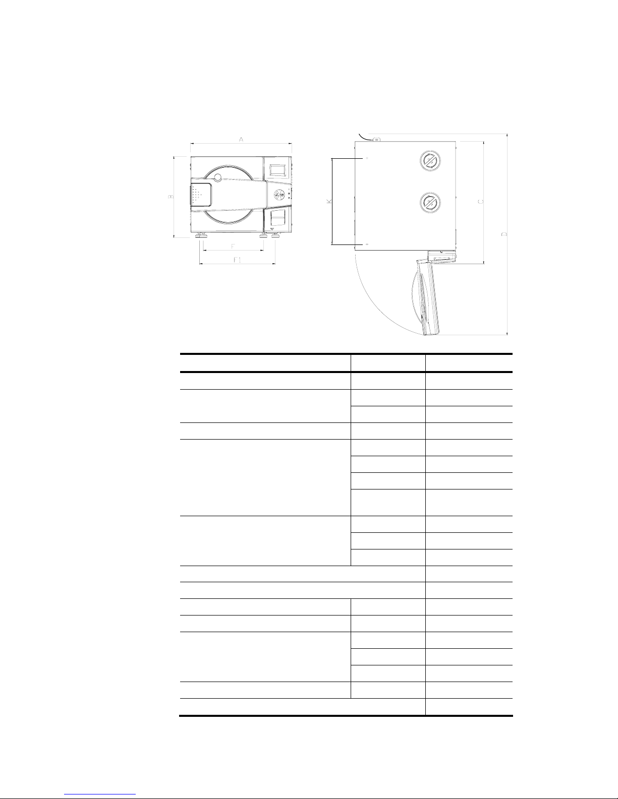
3.4. Specifications
Overall Dimensions
Property Value
Max. Allowable Working Pressure (MAWP)
2.8 bar (40 psi)
Diameter
280 mm (11”)
Chamber
Depth
504 mm (19.8”)
Chamber volume
28.5 lit. (7.5 gal)
Width (A)
530 mm (20.8”)
Height (B)
444 mm (17.4”)
Length (C)
645 mm (25.4”)
External dimensions
Length with
open door (D)
950 cm (36.6”)
K
452 mm (17.8”)
F
315 mm (12.4”)
Distance between supporting legs
F - rear legs
F1 - front legs
F1
400 mm (15.7”)
Maximum load per item
0.5 kg (1.1 lb)
Maximum load per tray
2.0 kg (4.4 lb)
Maximum solid load
8.0 kg (17.6 lb)
Maximum textile load
2.0 kg (4.4 lb)
W
212 mm (8.3”)
H
21 mm (0.8”)
Tray dimensions
L
350 mm (13.7”)
No. of trays
5
IMS cassettes (optional)
4
Top View Front View

Page 10 of 56
Property
Value
Weight
66 kg (145.5 lb)
Weight per support area (max. load)
1.71 N/m2
(0.036 lb/ft2)
Shipping weight
71 kg (156 lb)
Width
63 cm (24.8”)
Height
71 cm (28.0”)
Length
80 cm (35.8”)
Shipping dimensions
Volume
0.36 m3 (14.5 ft3)
Max. water
volume
6.6 lit. (1.74 US gal)
Mineral-free water reservoir
Min. water
volume
2.6 lit. (0.68 US gal)
Used (waste) water reservoir
Max. water
volume
5.2 lit. (1.37 US gal)
3.5. Utilities
Utility Value
Mineral free water See table in para 3.10.
Power supply 1 phase, 208/240Vac, 50/60Hz
Recommended circuit breaker 15A
Attention:
The electrical net must be protected with a current leakage safety relay.
The electrical network must comply with local rules or regulations.
3.6. Environment Emission Information
1. The peak sound level generated by the autoclave is 65dBa with
background noise of 48 dBa.
2. The total heat per hour transmitted by the autoclave is <200Wh.
3.7. Electrical Data
Property Value
Total Power 2300W
Voltage
1 ph / 230 Vac
Amperage 10A
Protection against electrical shock Class I (IEC 60601-1)
Mains supply fluctuation +/- 10%
Note:
In order to avoid any injury by electrical hazard, it is
recommended that a ground fault protection device be installed in
the electrical panel feeding the autoclave (local codes may make
this mandatory).
Page 11 of 56
3.8. Construction
The main parts of the autoclave are made of materials as indicated
below:
• Chamber is built of stainless steel 316 L.
• Door is made of stainless steel 316.
• Trays are made of stainless steel 316.
• Water reservoir is made of polyethylene.
• Door handle is made of hard plastic material, which is safe to
touch and thermo-insulated.
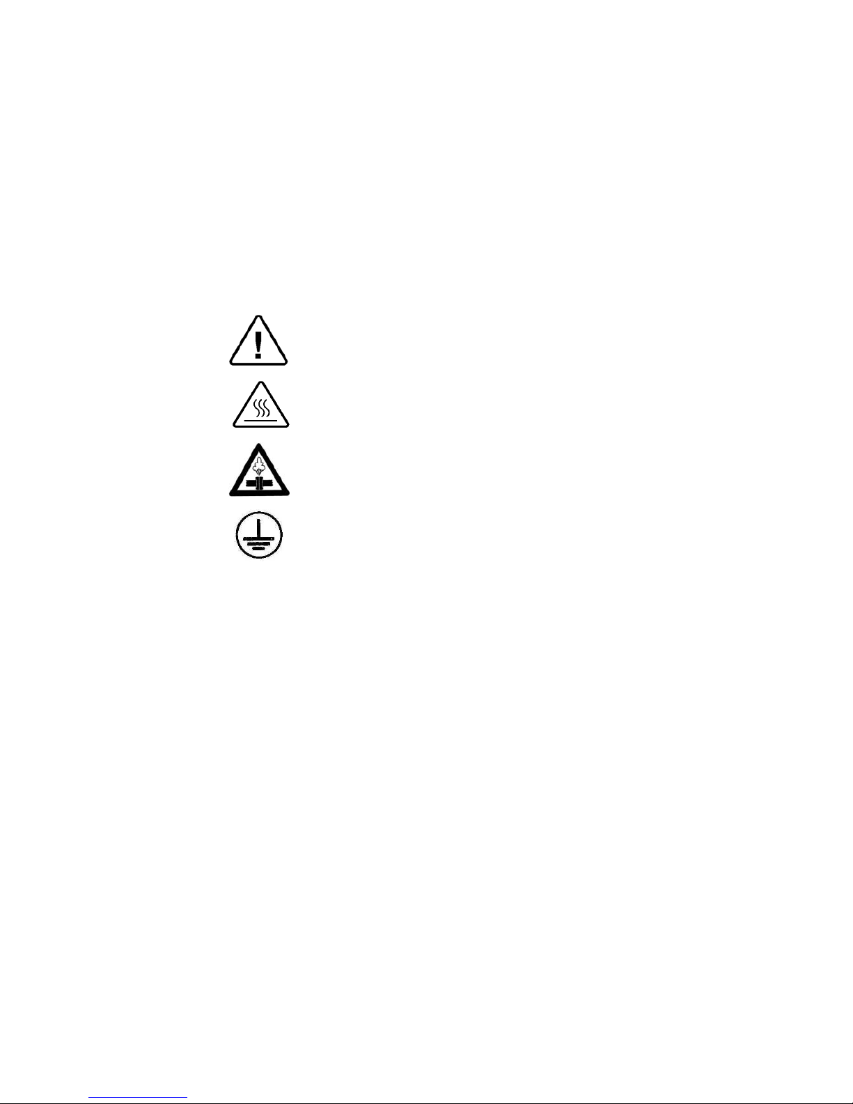
3.9. Symbol Description
Caution! Consult accompanying documents
Caution! Hot surface.
Caution! Hot steam.
Protective earth (Ground)

Page 12 of 56
3.10. Water Quality
Physical characteristics and contaminants levels
The distilled or mineral – free water supplied to the autoclave should
have the physical characteristics and maximum acceptable level of
contaminants indicated in the table below:
Physical Characteristics and Maximum acceptable contaminants
levels in water or steam, for steam generator and sterlizers
(According to EN 285:2006).
Contami
nants in water
supplied to
generator
1.1.1.2 Contamin
ants in
condensate
at steam
inlet to
chamber
Evaporate residue
≤ 10
mg/l
N/A
Silicate (SiO2
≤ 1
mg/l
≤ 0.1
mg/l
Iron
≤
0.2mg/l
≤
0.1mg/l
Cadmium
≤
0.005 mg/l
≤
0.005 mg/l
Lead
≤ 0.05
mg/l
≤ 0.05
mg/l
Rest of heavy metals except
iron, cadmium, lead
≤ 0.1
mg/l
≤ 0.1
mg/l
Chloride (Cl)
≤ 2
mg/l
≤ 2
mg/l
Phosphate (P2O5)
≤ 0.5
mg/l
≤ 0.5
mg/l
Conductivity (at 25°C)
≤ 15
µs/cm
≤ 3
µs/cm
pH value (degree of acidity)
5 to
7.5
5 to 7
Hardness (Σ ions of alkaline
earth)
≤ 0.02
mmol/l
≤ 0.02
mmol/l
Appearance
Colourless, clean, without
sediments
Compliance with the above data should be tested in accordance
with acknowledged analytical methods, by an authorized
laboratory.
Attention:
We recommend testing the water quality once a month. The use of
water for autoclaves that does not comply with the table above may
have severe impact on the working life of the sterilizer and can
invalidate the manufacturer’s guarantee.

Page 13 of 56
3.11. Directives and Standards
Every autoclave meets the provisions of the following Directives and is
in compliance with the following Standards:
3.11.1. Technical Standards
1. EN 13060:2004 – Small Steam Sterilizers.
2. ASME Code, section VIII division 1 for pressure
vessels.
3. EN 61326, Electrical equipment for measurement,
control and laboratory use-EMC requirements
4. UL/IEL/EN 61010-1 electrical equipment for
laboratory use; general requirements
5. UL/IEL/EN 61010-2-041 particular requirements for
autoclaves using steam for the treatment of medical
materials and for laboratory processes
6. UL/IEL/EN 61010-2-040 particular requirements for
sterilizers and washer disinfectors used to treat medical
materials.
The following standards were taken in consideration:
7. EN 554 Sterilization of Medical Devices - Validation
and Routine Control of Sterilization by Moist Heat
8. ISO 13683 Sterilization of Health Care Products -
Requirements for Validation and Routine Control of
Moist Heat Sterilization in Health Care Facilities
3.11.2. Quality standards
The manufacturing plant meets the following quality
standards:
1. EN ISO 9001:2000– Quality System
2. ISO 13485:2003 – Quality systems – Medical devices –
Particular requirements for the application of ISO 9001.
Page 14 of 56
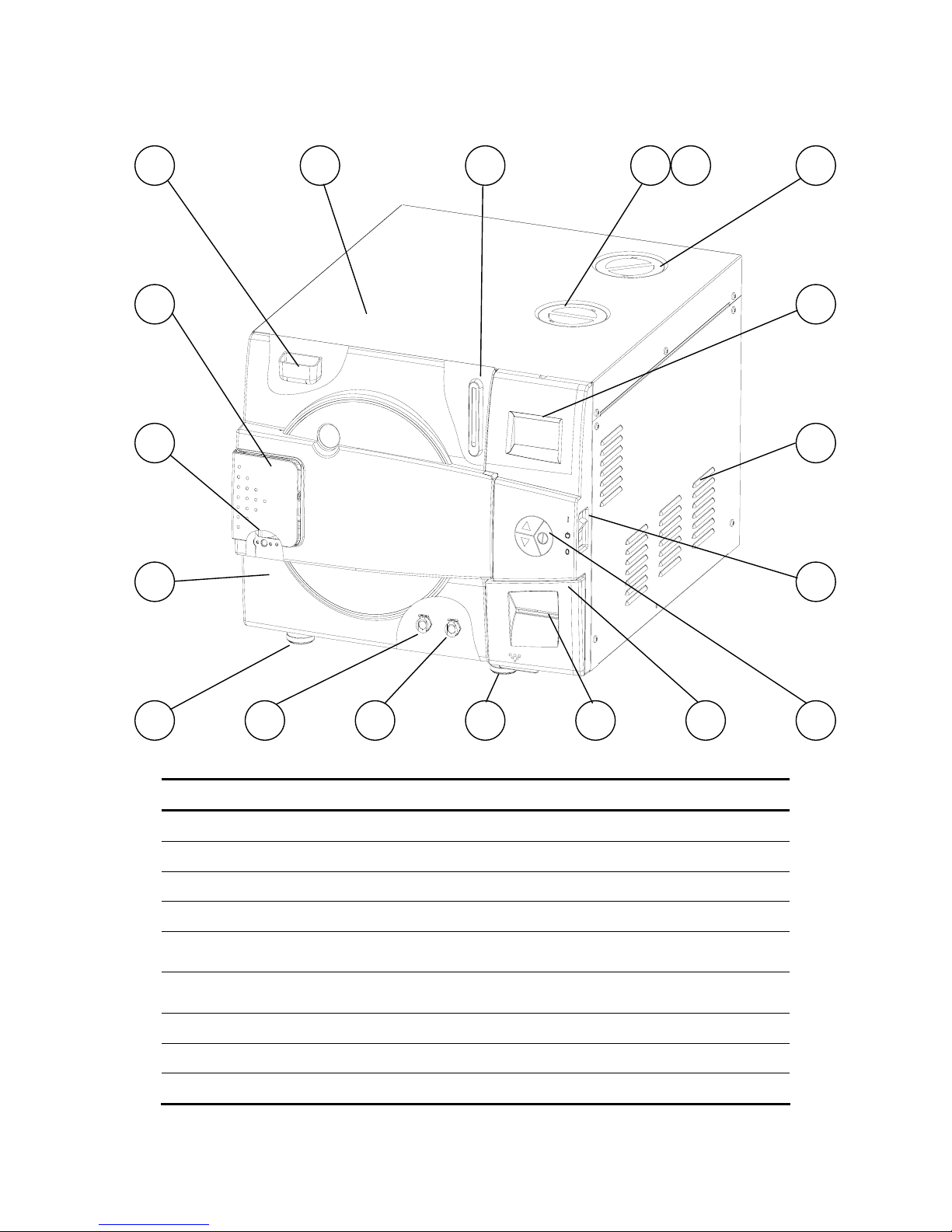
FRONT VIEW
No.Description No. Description
1 Water reservoir funnel 10 Operating key board
2 Autoclave cover 11 Printer cover
3 Water level side gauge 12 Printer (option)
4 Mineral-free water reservoir cover 13 Legs
5
Chamber and steam generator safety
valves
14 Waste water reservoir drain valve
6 Waste water reservoir cover 15
Mineral-free water reservoir drain
valve
7
Display 16 Door cover
8 Ventilation grill 17 Door switch
9 Main switch circuit breaker 18 Door closing device
5 4 6
8
9
101115 13 12
1 2 3
718
17
16
13 14
Page 15 of 56
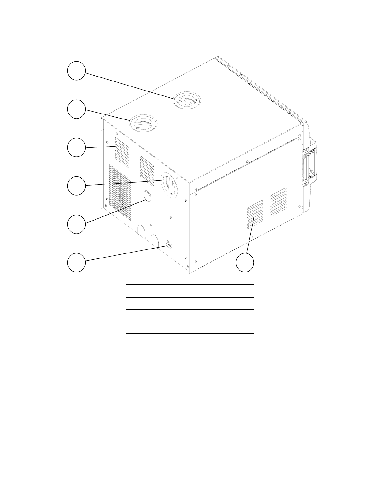
REAR VIEW
No.Description
1 Mineral-free water reservoir cover
2 Waste water reservoir cover
3 Ventilation grills
4 Air filter service cover
5 Opening for calibration
6 Main power electric cable socket
5
4
3
1
2
3
6
Page 16 of 56
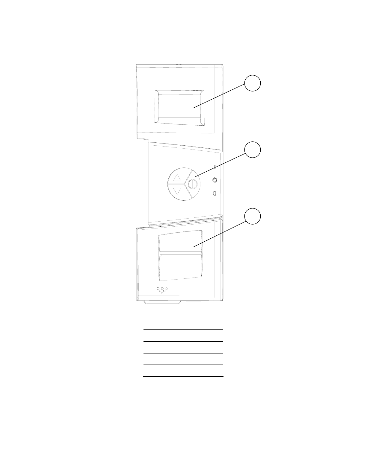
4. KEYBOARD
No
.
Description
1 Display
2 Keypad
3 Printer
2
3
1
 Loading...