

Page 1

OPERATION
&
MAINTENANCE
MANUAL
Pre-vacuum Steam Heated Autoclave
with One Manual Hinged Door
Model 5596 SP-1R ND
S.N.: 2912082
Cat. No. MAN205-0076072EN Rev A May 2010
Manufactured by: Tuttnauer Co. Ltd., Har Tuv Industrial zone B P.O. Box 170, Beit Shemesh 99000, Israel.
Tel: 972 2 9904611, Fax: 972 2 9904730
Tuttnauer USA Co., 25 Power Drive Hauppauge, NY, 11788, USA, Tel:(800)624 5836, (631)737 4850
Fax:(631)737 07 20
Page 2

Page 3

Table of Contents
INCOMING INSPECTION.....................................................................................1
SAFETY INSTRUCTIONS ....................................................................................2
1. GENERAL INFORMATION
1.1 Introduction ..........................................................................................4
1.2 Standards.............................................................................................6
1.3 Specifications .......................................................................................6
1.4 Symbol Descriptions.............................................................................7
1.5 Utility Labels.........................................................................................7
2. INSTALLATION
2.1 Environmental Conditions ....................................................................8
2.2 Mounting ..............................................................................................8
2.3 Preliminary Check ................................................................................10
3. FUNCTIONAL DESCRIPTION
3.1 The Piping System ...............................................................................11
♦ Piping System Drawing ........................................................................12
3.2 The Pneumatic Control System............................................................13
♦ Pneumatic Control System Drawing.....................................................14
3.3 Absolute Pressure Transducers ...........................................................15
3.4 The Electrical System...........................................................................16
3.5 The Control System..............................................................................17
♦ Safety Interlock Devices.......................................................................19
♦ Electrical Control System Drawing .......................................................20
3.6 Water Quality .......................................................................................21
4. CONTROL AND MONITORING
♦ Control Panel CAT 2007 ......................................................................22
4.1 Description of panel CAT 2007 ............................................................23
4.1.1 KeyPad....................................................................................23
4.1.2 Display.....................................................................................25
4.2 Description of Displayed Messages and Safety Measures...................27
4.3 Operating the Control Panel.................................................................29
4.3.1 Starting up the system.............................................................29
4.3.2 Selecting a Cycle.....................................................................30
4.3.3 System Setup (Changing Parameters and Values) .................33
4.3.4 Changing Cycle Parameters....................................................36
4.3.5 Door Display Function .............................................................41
4.3.6 Display during a Cycle.............................................................42
Page 4

Table of Contents (Cont.)
5. PRINTER
5.1 Printer Output.......................................................................................43
5.2 Printer Operation..................................................................................45
5.3 Printing Paper ......................................................................................46
5.4 Mechanical Alarm.................................................................................48
5.5 Auto Loading Function .........................................................................48
6. STERILIZATION PROGRAMS
6.1 Program Descriptions...........................................................................49
7. PREPARATION BEFORE STERILIZATION ..............................................58
7.1 Loading ................................................................................................59
7.2 Un-loading............................................................................................60
8. OPERATING INSTRUCTIONS ...................................................................61
8.1 Failed Cycle .........................................................................................62
8.2 Aborting a Cycle...................................................................................62
8.3 Repeating a Cycle................................................................................63
SERVICE INSTRUCTIONS
9. MAINTENANCE OF THE AUTOCLAVE
9.1 Preventive and Periodical Maintenance ...............................................66
9.2 Safety Tests after Repair......................................................................70
9.3 Troubleshooting ...................................................................................71
9.4 Test Points - Cat 2007..........................................................................74
9.5 Calibration ............................................................................................75
9.5.1 Calibrating Temperature and Pressure....................................76
9.5.2 An Example of Temperature Calibration..................................78
9.6 Testing the Safety Valves.....................................................................79
9.7 Replacing the Door Gasket ..................................................................80
10. SPARE PARTS...........................................................................................81
11. VALVES NUMBERING...............................................................................84
12. PRESSURE Vs TEMPERATURE TABLES................................................86
♦ XPCS MANUAL...................................................................................91
♦ MODEM CONNECTION ......................................................................105
♦ APPENDIX 1: Cabinet Side Panels
♦ APPENDIX 2: Exploded View of Door Locking Mechanism
♦ Set of Drawings
Page 5

INCOMING INSPECTION
Upon receipt, the autoclave should be unpacked and inspected for mechanical damage.
Observe packing method and retain packing material until the unit has been inspected.
Mechanical inspection involves checking for signs of physical damage such as:
scratched panel surfaces, broken knobs, etc.
If damage is apparent, file a claim with the carrier. The manufacturer is responsible for
products supplied Ex Factory. These products are carefully inspected prior to shipment
and all reasonable precautions are taken in preparing them for shipment to assure safe
arrival at their destination.
WARRANTY
We certify that this device is guaranteed to be free from defects in material and
workmanship for one year against faulty components and assembly with the exception
of glassware, lamps and heaters.
The warranty does not include and does not replace routine treatment and preventive
maintenance to be performed according to instructions in the Preventive and Periodical
Maintenance paragraph.
Our obligation is limited to replacing the device or parts, after our examination, if within
one year after the date of shipment they prove to be defective. This warranty does not
apply to any device that has been subjected to misuse, neglect, accident or improper
installation or application, nor shall it extend to products, which have been repaired or
altered outside the factory without prior authorization from us.
The autoclave should not be used in a manner not described in this manual!
Note:
If there is any difficulty with this instrument, and the solution is not covered in
this manual, contact our representative or us first.
Do not attempt to service this instrument yourself.
Stipulate the model and serial number and describe the difficulty as clearly as possible
so that we may be able to identify the problem and hence provide a prompt solution.
For technical information or service please contact us at:
Tuttnauer USA Co,
25 Power Drive Hauppauge,
NY 11788,
USA,
Tel: (800)624 5836, (631)737 4850
Page 1 of 105 pages
Page 6

Safety Instructions
The autoclave has unique characteristics. Please read and understand the operation
instructions provided by the manufacturer before the first operation of the autoclave. The
following issues may require clarification: The operation of the autoclave; the door safety
mechanism; the door closing mechanism; the dangers involved in circumventing safety
means; and finally, the selection of an appropriate sterilization program.
Make sure that you know the placement of the main power switch, the position of the
water cut-off valve, where the steam and compressed air disconnection valves are
located.
Autoclave maintenance is crucial for the correct and efficient function of the device.
The daily B&D test and the weekly spore test are part of the preventive maintenance
plan, along with the annual validation of the sterilization processes that ensures
appropriate temperature dispersion within the chamber.
Warning!
Never use the autoclave for the sterilization of corrosive products and chemicals,
such as: Acids, bases and phenols, volatile compounds or solutions such
ethanol, methanol or chloroform nor radioactive substances.
Safety Operation Instructions
1. NEVER start a new autoclave or a new steam generator, before the safety,
licensing, and authorization department has approved it for use.
2. All autoclave users must receive training in proper usage from an experienced
employee. Every new employee must undergo a training period under an
experienced employee.
3. A written procedure must be established for autoclave operation, including:
Daily safety tests; seal inspection and door hinge inspection; smooth action of
the closing mechanism; chamber cleaning; prevention of clogging;
preservation from corrosion; and finally, what is permitted and what is
prohibited for sterilization and choosing a sterilization program.
4. If there is a steam generator – drain it daily.
5. If there is an air compressor – drain it daily.
6. Before use, check inside the autoclave chamber to ensure that no items have
been left from a previous cycle.
7. Before loading the autoclave, clean the strainer on the chamber floor.
8. Load trays in such a way as to allow steam to move freely among all items.
9. Liquids may be sterilized only with the “liquids” program. The container must
be covered but not sealed. Sealed bottles may only be sterilized using a
special program. The bottle must be either Pyrex or a Borosilicate glass bottle.
Page 2 of 105 pages
Page 7

10. When sterilizing plastic materials, make sure that the item can withstand
sterilization temperature. Plastic that melts in the chamber is liable to cause a
great deal of damage.
11. Individual glass bottles may be placed within an appropriate container that will
be placed on a tray. Never place glass bottles on the floor of the autoclave.
Never fill more than 2/3 of the bottle volume.
12. On closing the autoclave door, make sure that it is properly locked before
activating.
13. Verify once, again that you have chosen the appropriate sterilization program.
14. Before withdrawing trays, wear heat resistant gloves.
15. Before opening the door, verify that there is no pressure in the chamber
(chamber pressure gauge is located on the autoclave's front panel).
16. Open the door slowly to allow steam to escape and wait 5 minutes before you
remove the load. When sterilizing liquids, wait 10 minutes.
17. Once a month, ensure that the safety valves are operating; and once a year,
that a certified inspector performs a chamber pressure safety test.
18. Once annually, or more frequently, effective tests must be performed, i.e.,
calibration and validation.
19. Check the condition of assemblies on a regular basis. Make sure there are no
leaks, breaks, blockages, whistles or strange noises.
20. Perform maintenance operations as instructed.
21. Notify the person in charge immediately of any deviation or risk of proper
function of the device.
22. It is strictly forbidden for any person to enter the autoclave’s chamber. If, for
any reason (for cleaning, maintenance or if something falls down), it is
necessary to enter the chamber, the person must ensure the system cannot be
accidently turned ON.
Instructions for Contaminated Waste
1. Verify that the contaminated waste at the sterilization station is packed in the
correct bags/containers.
2. Verify that there are no leaks and that the package is correctly marked.
3. Large containers with a narrow spout may “behave” like a sealed bottle.
4. It is preferable to sterilize solutions in small containers rather than in
differently-sized containers or in large containers.
5. It is recommended not to stand in front of the door when it opens, because
steam may be discharged when the door is opened.
6. It is recommended to support sterilization bags at the bottom – especially when
they are hot.
Attention:
IF THE UNIT IS USED IN MANNER NOT SPECIFIED BY THE MANUFACTURER,
THE PROTECTION PROVIDED BY THE EQUIPMENT MAY BE IMPAIRED.
KEEP THE DOOR CLOSED DURING THE DAY OR SHIFT. WHEN THE AUTOCLAVE
IS NOT OPERATING, AT NIGHT OR ON THE WEEKEND, LEAVE THE DOOR OPEN.
Page 3 of 105 pages
Page 8

1. GENERAL INFORMATION
1.1 Introduction
This autoclave is designed to cover a large field of applications for hospitals and medical
centers as well as pharmaceutical and biotechnological industries.
The autoclave operates with saturated steam as the sterilizing agent, and has a
temperature range of up to 279ºF (137°C) and pressure up to 34 psi (2.3 bars).
The autoclave is equipped with one manual hinged door, locked and unlocked by
rotating wheel located on front of the door. The door locking mechanism incorporates a
safety lock which prevents the door locking mechanism from rotating, locking the door in
the closed position while there is pressure in the chamber. This is achieved by means of
a pneumatic cylinder controlled by a pressure switch sensing the pressure inside the
sterilization chamber. The moment this pressure switch senses a pressure above 2 psig,
the pneumatic cylinder enters the door locking mechanism preventing it from rotating,
and will only be released when the chamber pressure drops below 2 psig.
The interlock system of the door is based on the following opening conditions:
♦ The door cannot be opened while the autoclave is in operation.
♦ The door cannot be opened if the chamber is under pressure.
♦ The door cannot be opened if there is liquid in the chamber.
♦ A door cannot be opened at the end of the cycle if:
a. the chamber temperature is higher than the preset final temperature, or
b. the liquid load temperature is higher than the preset final temperature.
The sealing of the chamber is achieved through a heat resistant silicone gasket, located
in a groove around the door opening of the autoclave.
The control system of the sterilizer is based on microcomputer technology, ensuring a
highly reliable and safe operation. The computerized control unit ensures a fully
automatic operation through the entire cycle; hence, after setting the pre-selected
parameters and starting the operation, no further operator intervention is necessary.
The autoclave has an automatic shutdown system. If no buttons or switches are
operated for four hours, it will go into SLEEP mode and a LED lights up (blinking every
second), indicating that the system is in the SLEEP mode.
The selected program, the main phases of the cycle and the status of the machine are
controlled and displayed on digital readouts. For process documentation, the important
information concerning operation is printed.
The system is equipped with four temperature sensors, two pressure transducers, two
pressure gauges, and safety devices having the following functions:
The temperature sensors are located:
1. In the drain – (control)
2. In the condensate line(double) – (control, monitoring, and printout)
3. In the chamber – (control, monitoring, and printout)
4. In the chamber dedicated to the independent Eliwell temperature controller
Page 4 of 105 pages
Page 9

The pressure transducers measure:
1. Chamber pressure – (control, display, and printout)
2. Jacket pressure – (control and monitoring)
The pressure gauges:
1. Chamber pressure
2. Jacket pressure
The safety devices:
1. RT112 pressure switch – (prevents the opening of the door if there is pressure
in the chamber).
2. A GICAR controller connected to a water level electrode which detects if there
is any liquid in the chamber.
4. An Eliwell temperature controller connected to a PT100 in the chamber
prevents opening of the door if:
a. the chamber temperature is higher than the preset final temperature, or
b. the liquid load temperature is higher than the preset final temperature.
The keyboard located on the front panel enables the operator to select a sterilization
program, and start/stop a cycle.
A programming mode, which can be accessed by a code, enables the technician to set
up the system, set and change a number of additional parameters and operational
modes and performing a calibration.
Optionally, a personal computer can be connected to the control system, through the
interface board RS232, which can be operated up to 8 meters away from the autoclave.
The PC, operating under WINDOWS displays the status, data and processing in real time
in graphic and digital form at the same time recording and logging the data. For a distance
more than 8 meters, a RS 485 interface and a modem are required.
The communication PC-control unit utilizing ADMC software enables the complete
control of the autoclave through the PC, including program selection, starting and
stopping a cycle, setting of parameters, and the real time clock (date and time of the
day).
Warning!
Do not operate the autoclave in the presence of dangerous gases and vapors.
It is strictly forbidden to enter the autoclave chamber!
If, for any reason (for cleaning, maintenance or if something falls down), it is
necessary to enter the chamber, the person must lock the system by pressing the
emergency switch and take the key with him to prevent accidents and
unauthorized use.
Page 5 of 105 pages
Page 10
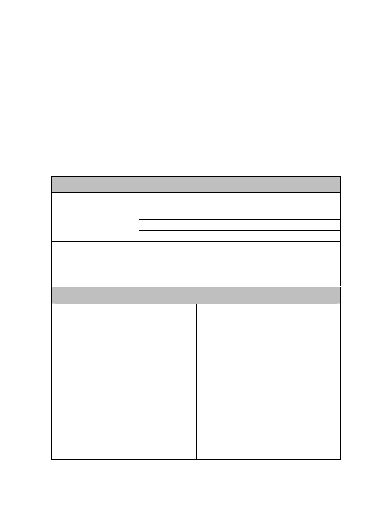
1.2 Standards
W 510 mm
20"
H 5
10 mm
20"
D 970 mm
38"
W 710
mm
28"
H 1910
mm
75"
L 1520
mm
60"
Degree of protection
IPX 4
Tuttnauer company meets the provisions of the Medical Device Directive 93/42EEC
and PED 97/23EEC and the following standards:
ASME American Society of Mechanical Engineers
Section VIII, Division 1, for unfired pressure vessels.
AAMI/ANSI-ST8 Hospital sterilizers
EN 285 Large Sterilizers.
EN 554 Validation and routine control.
UL Underwriters Laboratories, Inc.
Tuttnauer company is also approved for ISO 9001; 2008 (Quality Systems) and ISO
13485 (Quality Systems for Medical Devices).
1.3 Specifications
Product data
Model 5596 SP-1R ND
Chamber volume 250L
Chamber dimensions
External dimensions
Utilities
Tap Water supply
Maximum hardness value 0.7-2.0
mmol/l.
Recommended temperature 60°F (15°C)
Compressed air requirements
1. Connection: ½" thread.
2. Pressure: 30–70 psi (2–5 bar)
1. Connection: ¼" thread
2. Pressure: 85-115 psi (6-8 Bar)
3. Consumption: 3.5 SCFM
Steam
Electrical data 1 Ph, 115V/ 60Hz, 3 A
Electric cable requirements 3 X 13 AWG
1. Connection: ½" thread
2. Pressure: 50-65 psi (3.5-4.5 bar)
Page 6 of 105 pages
Page 11
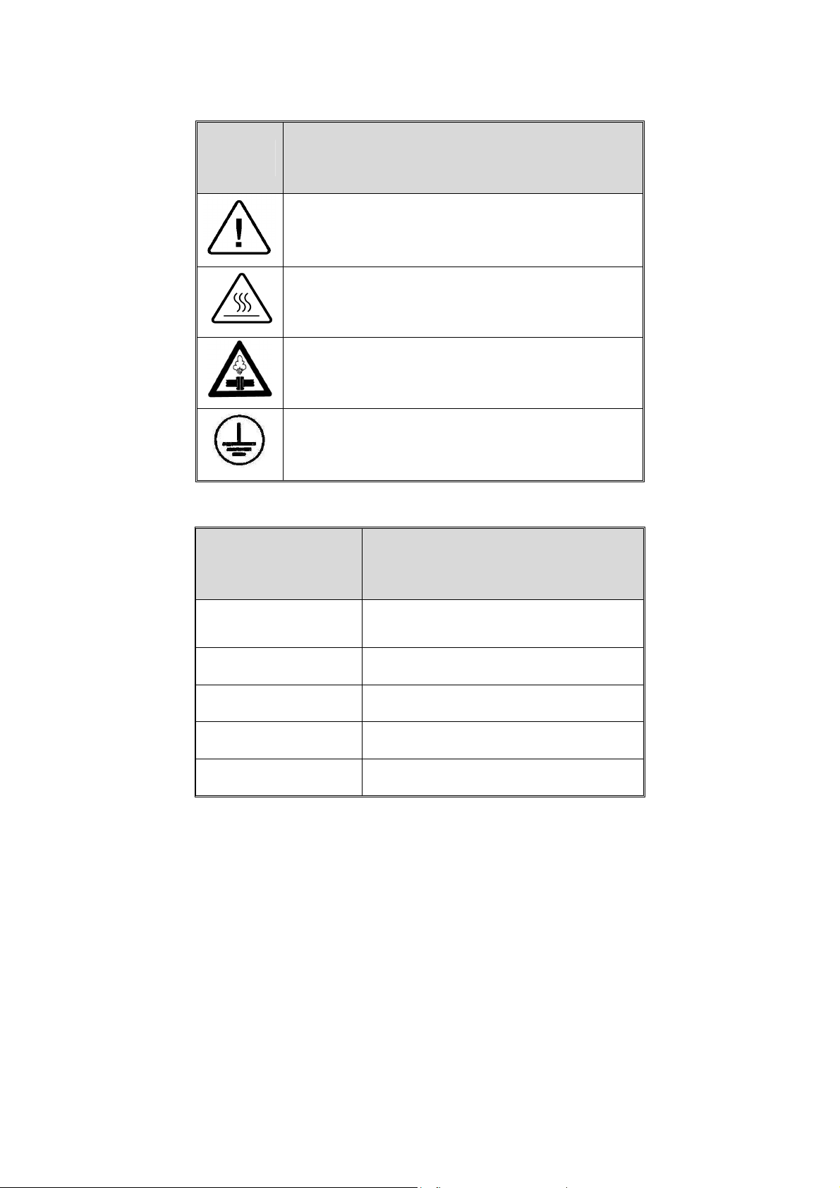
1.4 Symbol Description
Symbol
1.5 Utility Labels
Description
Caution! Consult accompanying documents
Caution! Hot surface.
Caution! Hot steam.
Protective earth (Ground)
Utility Specification
Mineral Free Water
(If required)
Tap Water
Steam
Compressed Air
Electricity
30–70 psi (2–5 bar)
30–70 psi (2–5 bar)
50-65 psi (3.5–4.5 bar)
85–115 psi (6–8 bar)
1 Ph, 115V/ 60Hz, 3 A
Page 7 of 105 pages
Page 12

2. INSTALLATION
2.1 Environmental Conditions
Ensure all shut-off valves or switches from the building services to the autoclave, for
example compressed air, electricity, steam, water, etc. are clearly marked, and are
located in an easy to reach, unrestricted area.
Ensure all personnel working with or around the autoclave are properly trained in the
location of all the shut off valves and switches that supply services from the building to
the autoclave.
The ambient atmosphere around the autoclave must not exceed 104 ºF (40 ºC), 80%
relative humidity, and the room should be ventilated 10 air changes/hour.
Place warning signs related to the possible dangers of operating autoclaves in
prominent positions. See the Symbol Description paragraph for explanations of the
dangers.
Warning!
Do not use the autoclave in presence of dangerous gases and vapors.
2.2 Mounting
Place the autoclave on a suitable level surface, leaving adequate space around it for
operation and service requirements.
Level the autoclave before connecting the utilities.
Utilities
Connect the autoclave to the utility supplies as follows:
Air
Connect the air connection of the autoclave to the compressed air supply of the building
by means of a ¼” pipe at Pressure: 85-115 psi (6-8 Bar)
Tap Water
Tap water for operating the ejector;
♦ Hardness should not exceed 0.7–2 mmol/l See also chapter "Water Quality".
♦ Pressure should be in the range of 30–70 psi (2–5 bar)
♦ Connection to the network by a ½” pipe.
Attention:
Connection of water system to the autoclave must be performed through
"BACK FLOW PREVENTION SYSTEM" installation as per EPA regulations and
local regulations.
Drain
♦ Connect the following outlets directly to the drain funnel. Or connect them
through a drain collector pipe of 4-6” that should be covered. The drain
system should be vented.
♦ General drain outlet by a ¾" pipe.
Page 8 of 105 pages
Page 13
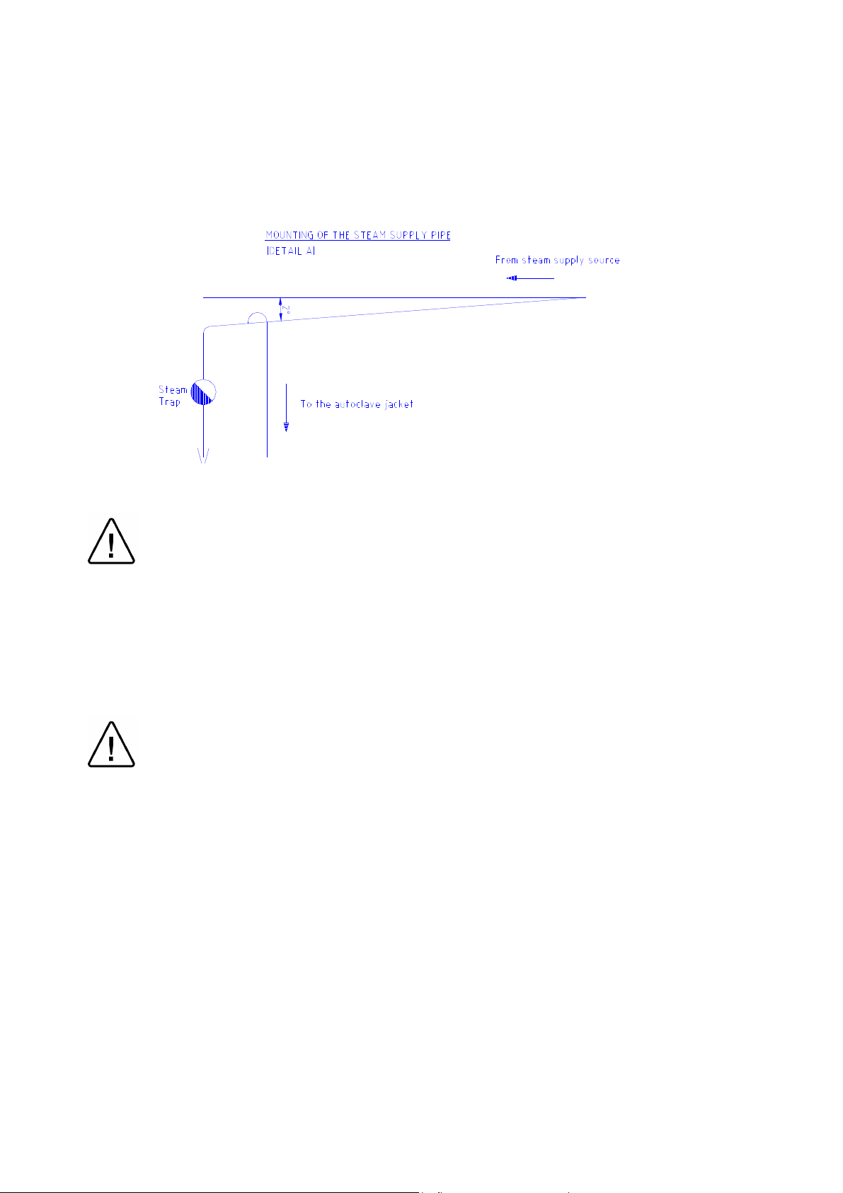
Steam
♦ Connect the building steam supply to the autoclave by ½ pipe.
♦ The steam supply pressure should be between 50-65 psi (3.5-4.5 bar). (See
also Utilities Table).
♦ The steam trap should not exceed 2 meters from the machine.
Electrical Power Connection
Warning!
Only a qualified electrician may perform the electrical connections!
The electrical units should not be placed near water sources.
Connect the power cord to the electric box of the autoclave
The electrical data is: 1 Ph, 115V/ 60Hz, 3 A
Electric cable requirements: 3 X 13 AWG
Warning!
It is strictly forbidden for any person to enter the autoclave chamber.
If, for any reason (for cleaning, maintenance or if something falls down), it is
necessary to enter the chamber, the person must lock the system by pressing the
emergency switch and take the key with him to prevent accidents and
unauthorized use.
Page 9 of 105 pages
Page 14

2.3 Preliminary Check
After installation, and prior to putting the machine into operation, the following checkout
procedure is to be fulfilled:
♦ Check connection to local sewage. Check that the sewage pipeline is not
clogged. (Pour water for this task).
♦ Check connection of the compressed air, pay attention to the door, set the
pressure to 85-115 psi (6-8 bar)
♦ Check connection to tap water. Open the water valve. Manually test the
water valves by over-riding the appropriate solenoid valve. If there are no
leaks, –leave the water manual inlet taps open.
♦ Check connection to steam. Open the steam valve. Manually test the steam
valves by over-riding the appropriate solenoid valve. If there are no leaks, –
leave the steam manual inlet taps open.
♦ Check connection to electricity –To be performed by an authorized
electrician only!
Performing Safety Tests
♦ Check the tightness of all the nuts and screws. Dismantle the cover of the
steam generator, (if applicable).
♦ Test the earth continuity
♦ Check current leakage. Check Voltage and Amperage.
♦ Check pressure setting of the steam.
♦ Adjust the legs of the transfer carriage to equal the height of loading cart to
rails in the sterilization chamber, (if applicable).
♦ Operate the generator, (if applicable).
♦ Run a cycle.
♦ Call for an authorized inspector to test and approve the autoclave; generator
and, assembled system.
Page 10 of 105 pages
Page 15

3. FUNCTIONAL DESCRIPTION
3.1 The Piping System
The piping system of the autoclave consists of air-operated valves, which control the
condensate and steam flow in and out of the chamber, operate the vacuum, and the air
inlet valve. The air pulses to the pneumatic valves are transmitted through solenoid pilot
valves, operated at 24VDC.
The functions of the valves are as follows:
Steam to jacket (91) – introduces steam into the jacket to accelerate the heating of the
chamber and to maintain a stable and uniform temperature in the chamber during the
sterilization and drying stages.
Steam inlet valve (93) – introduces steam from the jacket into the chamber, for heating
and maintaining the chamber temperature during the sterilization phase.
Air inlet valve (43) – introduces filtered ambient air into the chamber at the end of the
cycle to break the vacuum and enable the opening of the door.
Fast exhaust and vacuum valve (75) – This valve performs two functions:
1) To exhaust the steam from chamber.
2) To connect the chamber to the ejector to create vacuum in the chamber in the
air removal and drying stages.
Condensate valve (74) – evacuates the condensate from the chamber during heating
and sterilization phases and isolates the chamber from the drain pipe, during vacuum
generation. It operates like a slow exhaust valve at the end of slow pressure programs.
Water to ejector valve (15) – is connected to the tap water and supplies the water
required by the operation of the ejector.
Note:
The valve numbers are in accordance with the valve numbering list and piping
diagram.
Page 11 of 105 pages
Page 16
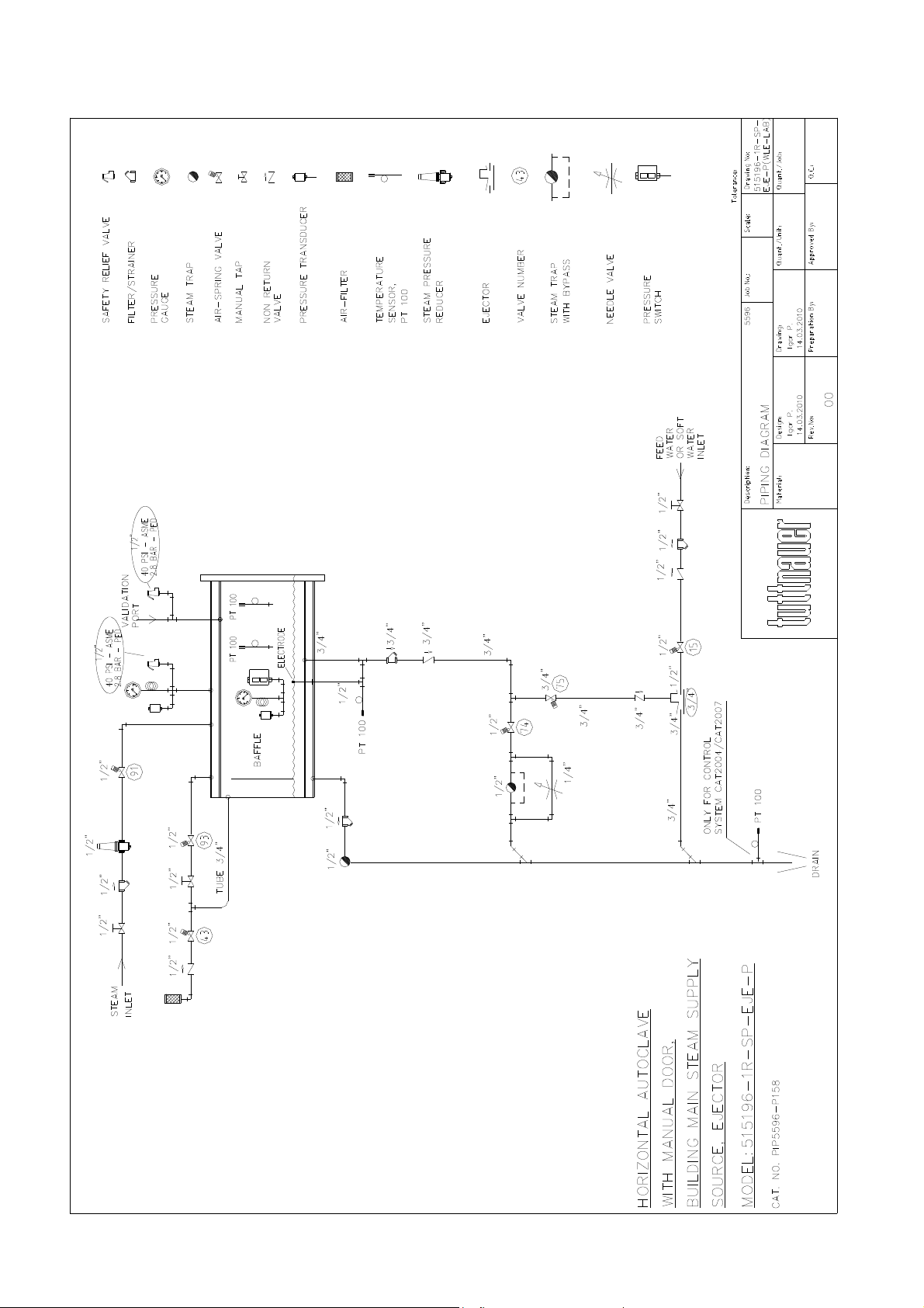
PIPING SYSTEM DRAWING
Page 12 of 105 pages
Page 17

3.4 The Pneumatic Control System
The control of the pneumatic valves is done through compressed air, as described
below:
The compressed air supply at a pressure of 6-8 bar (85-115 psi), and is reduced by a
pressure reducer to 6 bars (85 psi) and transmitted to the inlet of the pilot solenoid valve
battery.
The pneumatic control system is built as follows (refer to drawing on the next page):
Air is transmitted to the inlet of the pilot solenoid valve battery, which is mounted on a
manifold branch base. Through the manifold, all the solenoids are connected to the
compressed air supply.
The 24VDC solenoids are operated by controller.
When the solenoid is operated, it transfers the compressed air to activate the
appropriate air valve.
The pneumatic valves are air operating, and spring closing valves:
Air-activated and spring-return are fitted with two commands:
An opening command comes from a solenoid valve at a pressure of 6 bars output by the
control system, and a permanent closing by a built-in spring valve.
Pneumatic safety measures:
♦ RT112 pressure switch prevents the opening of the door if there is pressure
in the chamber.
Page 13 of 105 pages
Page 18
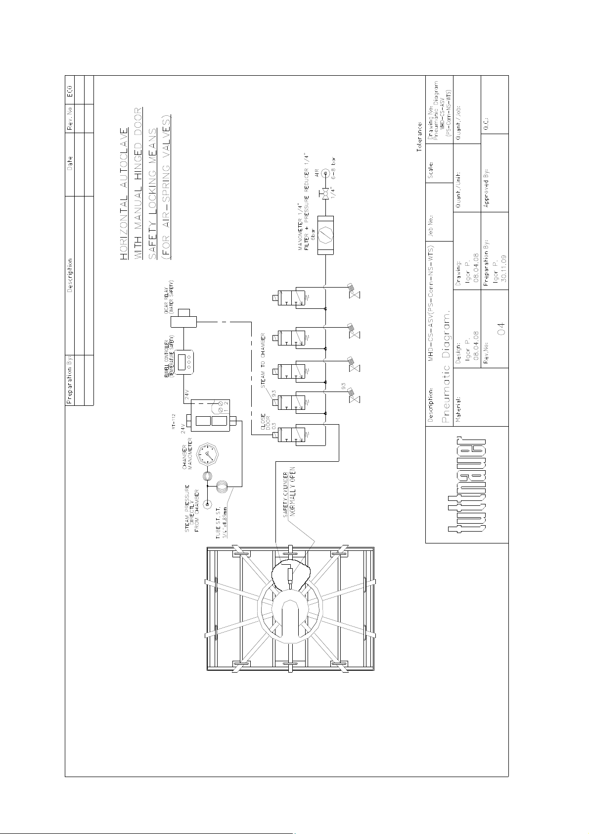
PNEUMATIC CONTROL SYSTEM DRAWING
Page 14 of 105 pages
Page 19
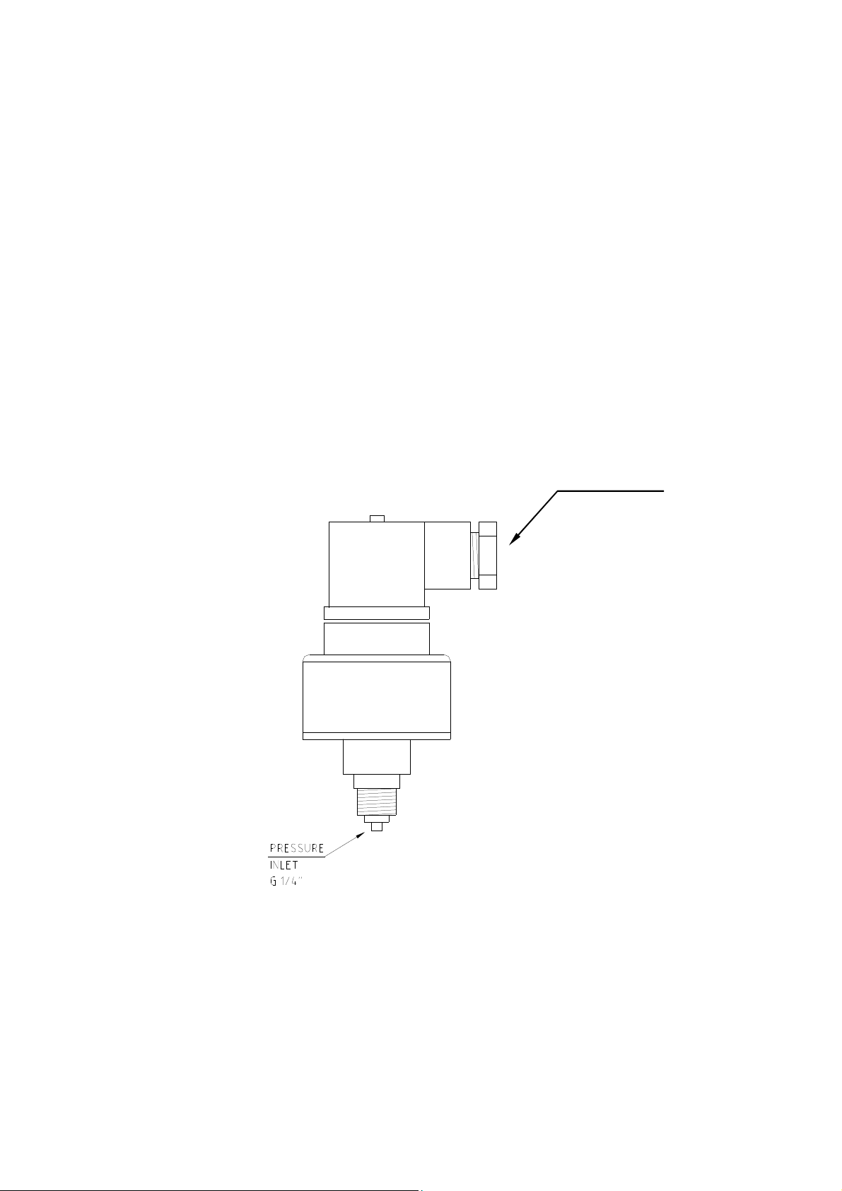
CONNECTIONS
3.3 Absolute Pressure Transducers
The transducer type MT 3296 is a membrane pressure sensor and electronic measuring
circuit, with the following specifications:
♦ Pressure range: 0–58 psia (0-4bar).
♦ Output span current: 4-20mA
♦ Supply voltage: 10V to 30V
The autoclave is fitted with two pressure transducers for controlling & monitoring:
1. Chamber pressure – (control, display, and printout)
2. Jacket pressure – (control and monitoring)
The terminals at the connector of the device are 1 (+24V) and 2 (OUT) to the controller
output.
ELECTRIC
Page 15 of 105 pages
Page 20

3.4 The Electrical System
The electrical system of the autoclave comprises the power circuits including the
commands, switching, and protective components required for the operation of the
electrical equipment of the unit.
The following parts are located in the electrical box, mounted on the upper side of the
autoclave:
♦ Electrical control board.
♦ Circuit breakers for protection of all power circuits.
♦ Power supplies for powering of electronic circuitry and solenoid valves.
♦ Wiring and connection elements.
♦ One main power switch.
It is important to achieve a good grounding connection to the metal-sheet enclosure of
the electric box and metal parts of the autoclave.
The earth installation at the customer’s site must be built in compliance with the laws
and regulations of the NEC.
Caution!
Only authorized electricians are allowed to install or attend the electrical system!
Description of the Electrical Equipment (see Electrical Drawings)
The command circuits are energized by a power supply with two outputs, as indicated
below:
♦ 5 VDC for the digital circuits.
♦ 24 VDC for the solenoid valves.
The coils of the solenoid valves are 24V and are operated by the controller. The
solenoid valves are activated when the control voltage output is low (less than 2V) with
respect to ground. A Circuit Breaker (CB1 4A) protects all power circuits.
Page 16 of 105 pages
Page 21

3.5 The Control System
The Main Board
Controls and monitors the physical parameters of the process and performs the
operation sequence of the machine, according to the selected program.
The main board contains the following elements:
♦ 16 digital inputs
♦ 24 digital outputs
♦ 6 PT 100 inputs
♦ 7 inputs of 4–20mA
♦ Voltage inputs for the electrodes for water level
♦ 2 analog outputs of 4–20mA
♦ Serial ports
♦ CPUs.
♦ 2 ADCs for reading temperature and pressure sensors.
Each ADC maintains at least 3 temperature sensors (PT100), and 3 pressure sensors
(4–20mA).
All connections to the main board are via rigid connectors for quick and efficient
dismantling.
Digital Inputs
The digital inputs are 0/1:
♦ Open/close for door positions
♦ Safety cut-off switches
♦ Pressure cut-off switches
♦ Switches for water level
The input voltage is 24VDC. The input is protected from high voltages by means of an
Opto-coupler.
Digital Outputs
Digital outputs are used to activate solenoid valves and relays.
Each output is up to 2A, however all the outputs together will not have a capacity higher
than 110 W.
The command voltage is 24 VDC, but it can vary in the range of 10–30VDC.
Analog inputs for Reading Temperature
Temperature is measured using PT100.
The system contains 2 ADC components, each component being able to read 3 PT100
sensors. The system contains circuits with a direct connection of PT100 (3 wires) that do
not interchange on the way.
The measurement range is 80–300ºF (25–150ºC).
The resolution is 0.2 ºF (0.1ºC).
The accuracy of the temperature is +
1 ºF (0.5ºC).
Calibration of the temperature circuits requires a special engineer access code.
Page 17 of 105 pages
Page 22

Analog Inputs for Control and Reading Pressure
The system contains 6 inputs for control and reading transducer pressure from
4–20mA sensors. There are at least 3 sensors on each ADC.
The chamber, the jacket, and the door gasket are monitored by the pressure
transducers.
Each sensor has an output of 4–20mA. The system allows the measurement range of
the sensor to be set by external software (via RS232).
Measuring chamber pressure
The display and printing scale are in kPa and psi units.
The measurement range is 30 inHg–72 psia (0-500 kPa).
The resolution measurement and display is 0.15 psi (1kPa).
The accuracy of the measurement is a maximum 1% of the range, i.e. 1.0 psi (+5 kPa).
Calibration of the pressure circuit requires a special engineer access code.
Measuring jacket pressure
The measurement range is 14.5–72 psia (100-500 kPa).
The resolution measurement and display is 0.15 psi (1 kPa).
The accuracy of the measurement is a maximum 1% of the range, i.e. 0.5 psi (+4 kPa).
Calibration of the pressure circuit requires a special engineer access code.
3 Serial Ports
The control system contains 3 serial ports (1optional) according to the following
specifications:
♦ 2 Serial Ports for the connection of up to 2 command panels.
♦ 1 Serial Port connected to an external PC computer (RS232/485).
♦ 1 Serial Port (optional)
Serial Port RS232 is included in the system to connect to an external PC up to a
distance of 8 meters. If it becomes necessary to convert certain functions, re-program,
re-load software of the autoclave from a distance of over 8 meters, a modem and Serial
Port RS 485 are required. This enables service technicians to attend to the unit from a
remote site. ADMC software enables full control of the autoclave.
Page 18 of 105 pages
Page 23
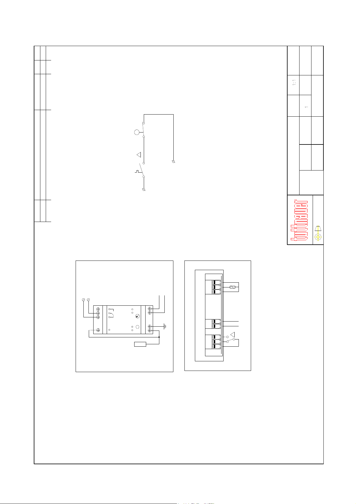
SAFETY INTERLOCK DEVICES
01
From GICAR
01
Description Date Rev. No ECO
Safety Interlock 2 (SI 2)
1 3 1 2
From Eliwell
+24V
ES1C01-0010
Drawing No.
Scale:
Job No.
Safety Interlocks schem
Description:
Q. C.
Cat. No.
Quant./Job:
Uri H.
12-7-09
Quant./Unit:
Approved by:
12-7-09
12-7-09
Marchel Nir
Marchel Nir
Prepared by:
Drawing:
01
Rev No.
Design:
Material:
A3
Marchel N. Change contacts to Eliwell from NC to NO 9/9/2009
Preparation By:
To RT112
ISO
Pt100
Power
+24V
To Eliwell
1 2
Sm
GICAR
L N
GICAR DRLH
SM R
(water )
Electrode high
Supply
Eliwell
10 11 12761 2 3
IC912
Sensor
Power
Supply
01
Out
Page 19 of 105 pages
Page 24
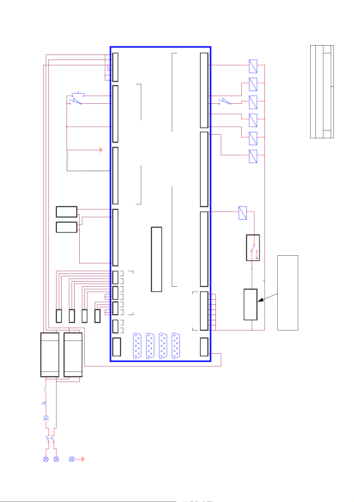
ELECTRICAL CONTROL SYSTEM DRAWING
GND
24V
5V
5V
GND
GND
Start switch
2
3
switch
Limit door1
CHAMBER
PRESS
JACKET
PRESS
1
2
YELLOW
RED
RED
RED
YELLOW
RED
RED
YELLOW
RED
RED
YELLOW
RED
RED
INPUT1
INPUT2
INPUT3
INPUT4
INPUT5
INPUT6
INPUT7
INPUT8
INPUT9
INPUT10
INPUT11
INPUT12
INPUT13
INPUT14
INPUT15
INPUT16
4-2 0mA
4-2 0mA
4-2 0mA
4-2 0mA
4-2 0mA
4-2 0mA
4-2 0mA
24V
1
2
3
4
5
6
PT100 SENSOR
CAT2007
INPUTS
OUTPUTS
DIGITAL
DIGITAL
TEST POINTS
OUTPUT1
OUTPUT2
OUTPUT3
OUTPUT4
OUTPUT5
OUTPUT6
OUTPUT7
OUTPUT8
OUTPUT9
OUTPUT10
OUTPUT11
OUTPUT12
OUTPUT13
OUTPUT14
OUTPUT15
OUTPUT16
OUTPUT17
OUTPUT18
OUTPUT19
OUTPUT20
OUTPUT21
OUTPUT22
OUTPUT23
OUTPUT24
1
2
5
6
7
8
1
12
15
12
43
12
Door switch
93
12
91
12
74
12
75
12
02
Water to ejector
of
1 1Sunday, May 23, 2010
Filtered air inlet
Steam inlet to chamber
Steam inlet to jacket
H01MU01NUSA301976
Slow exhaust to drain
A3
Electric control for horiz ont al autoclave with manual door
Title
Size Doc ument Number Rev
Date: Sheet
Exhaust to ejector
Door Lock
1
RT112
2
4
GICAR
PT100-1 CONDENSE
5V
GND
RS25-5
POWER SUPPLY
L
N
CB1 4A
1 2
12
Eme rgency sw.
1
S1
1 3
2 4
1
1
115V/60Hz
L
N
PT100-3 CHAMBER
PT100-2 CONDENSE
GND
24V
RPD-65D
POWER SUPPLY
N
L
1
PT100-5 COOLING DRAIN
GND
1
2
ANL OUT
1
2
3
PANEL1
PANEL2
ANL IN
RS232
Page 20 of 105 pages
POWER OUT 24VDC
GND
5V
24V
COMPUTER
SEE SAFETY INTERLOCKS
DEVICES INSTALLED HERE
Page 25
3.6 Water Quality
Physical Characteristics and Maximum acceptable contaminants levels in
water or steam, for steam generator and sterilizers
(According to EN 285:2006).
Contaminants in
water supplied to
generator
Contaminants in
condensate at
steam inlet to
sterilizer
Evaporate residue ≤ 10 mg/l N/A
Silicate (SiO2) ≤ 1 mg/l ≤ 0.1 mg/l
Iron ≤ 0.2mg/l ≤ 0.1mg/l
Cadmium ≤ 0.005 mg/l ≤ 0.005 mg/l
Lead ≤ 0.05 mg/l ≤ 0.05 mg/l
Rest of heavy metals
except iron, cadmium,
≤ 0.1 mg/l ≤ 0.1 mg/l
lead
Chloride (Cl) ≤ 2 mg/l ≤ 0.1 mg/l
Phosphate (P2O5) ≤ 0.5 mg/l ≤ 0.1 mg/l
Conductivity (at 25°C) ≤ 5 µs/cm ≤ 3 µs/cm
pH value (degree of
acidity)
5 to 7.5 5 to 7
Hardness (Σ ions of
alkaline earth)
≤ 0.02 mmol/l ≤ 0.02 mmol/l
Appearance Colorless, clean, without sediments
Compliance with the above data should be tested in accordance with acknowledged
analytical methods, by an authorized laboratory.
Attention:
The use of water for autoclaves that do not comply with the table above may have
severe impact on the working life of the sterilizer and can invalidate the
manufacturer’s guarantee.
Tap Water Supply
Maximum hardness value 0.7-2.0 mmol/l
Note:
The use of soft water for the steam generator is strictly forbidden! (If applicable)
Please consult a water specialist!
Page 21 of 105 pages
Page 26
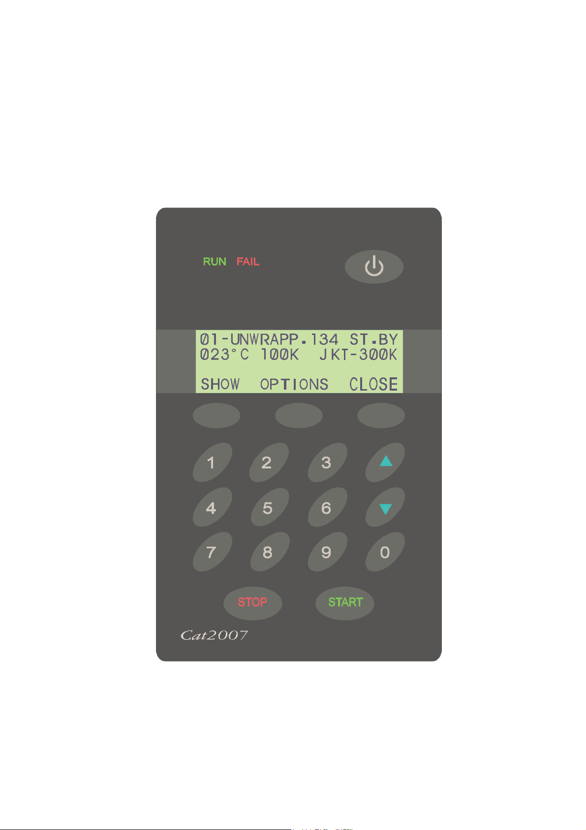
4. CONTROL AND MONITORING
Control Panel CAT 2007
Page 22 of 105 pages
Page 27
4.1 Description of Panel CAT 2007
The Operation Panel is consists of the following parts:
♦ 4 rows display, 20 characters in each row.
♦ 17 keys
♦ 2 LEDs (Fail, Run)
♦ 1 locking key
4.1.1 KeyPad
STANDBY
The ON/ST.BY key is located on the top right side of the panel. Press this
key to light up the operation panel. When there are 2 panels, both light up
even though only one was operated.
3 Command Keys
F1- 3: Functions 1- 3
F1 F2 F3
These keys are found under the display. The function to be performed is displayed
above each key.
10 Digit keys
These keys are used for 2 purposes:
Under normal working conditions the program option is used. Press on the number key.
For example, no. 3 selects program 3.
Under the display mode, the keys are used as number keys to enter a code or a
number.
UP/DN
Under normal working conditions, they are used to browse through the
different cycles.
Under set-up mode they change numeric value or move the display to the
next screen.
Page 23 of 105 pages
Page 28
START
When the autoclave is in the Ready position, pressing START activates
the cycle.
STOP
This key is active while the autoclave is in operation. Pressing STOP at
any stage of the cycle stops the operation.
Canceling the FAIL message
At the end of an aborted process the FAIL light is turned ON and an error message is
displayed on the screen indicating the cause of the failure.
Press the STOP key to cancel the displayed message and switch off the FAIL light.
RUN/FAIL LEDs
The operation panel contains 2 small LEDs which are located on the
top left corner. The RUN LED (green) lights when the autoclave is in
process. When the system has been turned OFF by the ST.BY key,
the RUN LED will flash for 1/2 a second for every 2 seconds indicating that the system is
still ON. The FAIL LED (red) lights when there is a problem with the system.
Page 24 of 105 pages
Page 29
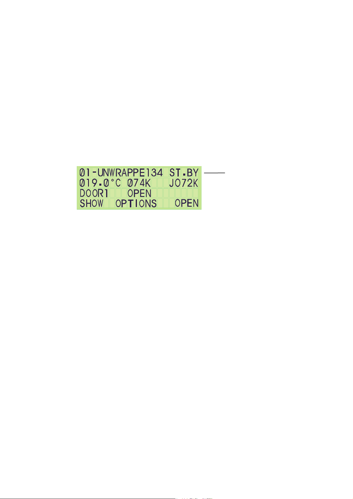
4.1.2 Display
Note:
Temperature and pressure measuring units differ according to the country of
operation. Temperature and pressure are displayed in both ºC or ºF and kPa or
psi, respectively.
The CAT2007 display consists of 4 alphanumeric rows with 20 characters in each row
(see Figure below)
First Row
First 3 characters define the Cycle no. (ranges from 1–14)
8 characters define the cycle name.
The 5 final characters at the right end of the row are allocated for displaying the status of
the autoclave or the stage of the cycle in operation.
First Row
1. ST. BY - indicates that the autoclave is in the waiting stage.
2. READY - indicates that the machine is ready for operation.
3. END - indicates that the process has ended correctly.
4. FAIL - indicates that the program has ended due to failure.
The names of the stages are:
♦ Vacuum
♦ Exh. (Exhaust)
♦ Heat
♦ Dry
♦ Ster. (sterilizing)
♦ Test
Page 25 of 105 pages
Page 30
The 14 cycles, names of programs and relevant temperatures are listed below:
Cycle no. Program Temp ºF
1, 2, 3 Un-wrapped 270
4, Un-Wrapped 270
5, 6 Wrapped 270
7 Wrapped 275
8 Wrapped 250
9, 10, 11, 12 Slow exhaust 250
13 B&D test 274
14 Leak test —
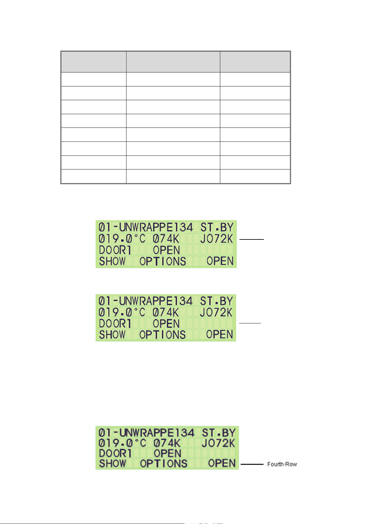
Second Row:
This row displays the temperature in the chamber, pressure in the chamber, and jacket
pressure.
Second Row
Third Row:
This row is used to display messages to the operator such as DOOR1 OPEN.
Third Row
Fourth Row:
On the bottom row, the names of the commanding keys appear. Under the display there
are three keys without symbols or names. These keys receive their commands by the
name that appears above them in the 4th row of the display. During a cycle, the fourth
row is used to display the timers, such as STE Time 02:25, or during pre-vacuum, to
display the stage of the pulse, such as puls1 – pump to 21K.
Page 26 of 105 pages
Page 31

4.2 Description of Displayed Messages and Safety Measures
This message is displayed and the FAIL indicator lights up
03 - Manual Stop
after the STOP key is pressed for more than 1 second during
the cycle (excluding the drying stage).
This message is displayed and the FAIL indicator lights up
100 - Man. Stop
after the STOP key is pressed for longer than one second in
the drying stage.
This message is displayed if either of the following occurs:
05 - Door Unlock
The START button is pressed and the door is not closed or
if during a cycle or the pressure drops in the gasket.
If the temperature sensor is disconnected for any reason
06 - Temp. Error
during the heating stage, temperature is either higher than
284ºF (140ºC) or lower than 41ºF (5ºC).
This message is displayed and sterilization does not start if
07 - Low Heat
the autoclave has not reached sterilization temperature after
heating for the maximum time as defined in the HEAT T.O.
parameter.
08 - Low Temp.
09 - High Temp.
10 - Low Pres.
11- High Pres.
12 - Low Vacuum
13 - Jacket not Ready
This message is displayed, fail indicator lights up and cycle is
aborted, if the temperature drops for more than 5 secs. below
the required sterilization temperature.
This message is displayed, fail indicator lights up and
program is aborted: If the temperature rises by 3ºC (5ºF)
above the required sterilization temperature during the
sterilization cycle.
This message is displayed, fail indicator lights up and the
program is aborted if the pressure drops for more than 5 sec.
below the pressure correlated to the required sterilization
pressure.
This message is displayed, fail indicator lights up and the
program is aborted, if pressure rises above the pressure
correlated to the sterilization temperature by 3ºC (5ºF) for
more than 5 sec.
This message is displayed if after 18 min. the system has not
reached at the Vac Dip1or Vac Dip2 values during the prevacuum stage. It also appears if the Leak Test program fails.
This message is displayed if the START key was activated
before the jacket reached the desired pressure.
21 - Door1 Safe Switch
(N/A)
22 - Door2 Safe Switch
(N/A)
If, while closing, Door #1 of an automatic sliding door, the
door safety bar feels resistance, the door will open, and this
message will appear.
If, while closing, Door #2 of an automatic sliding door, the
door safety bar feels resistance, the door will open, and this
message will appear.
Page 27 of 105 pages
Page 32

23 - Door1 Gasket Low
Vacuum
(N/A)
24 - Door2 Gasket Low
Vacuum
(N/A)
25 - Vac Res. Empty
27 - First Close Door
Informative Messages
Calibration This message appears on the panel during calibration.
Closing Door Wait
(N/A)
Open Door Wait
(N/A)
Door1 Open
(N/A)
Door2 Open
(N/A)
Door 1 & 2 Open
(N/A)
Under Test
(N/A)
This message indicates that during opening Door #1, you do
not achieve the proper vacuum in Gasket1.
If whilst opening Door #2 you do not achieve the proper
vacuum in Gasket2.
This message is a result of a safety mechanism indicating
that if during the pre-vacuum stage, drying stage, vac. test or
leak test it is revealed that the lower float switch in the
vacuum water reservoir is open for more than 1 second (so
there is no water entering the water reservoir and the pump
has therefore been closed to protect it).i.e. Vfloat –L = “1”
This message appears if there was an attempt to perform
IN/OUT Test while the door is open.
When an automatic door is closing, this message is displayed
so that the operator waits until the closing operation of the
automatic door is completed.
When an automatic door is opening, this message is
displayed so that the operator waits until the opening
operation of the automatic door is completed.
This message appears when Door1 is open. It will also
appear if the door is supposedly closed but there is not
enough pressure in the gasket to seal it properly.
This message appears when Door2 is open. It will also
appear if the door is supposedly closed but there is not
enough pressure in the gasket to seal it properly.
This message appears when both doors are open.
This message appears on panel 2 during the IN/OUT Test
and during Setup.
Page 28 of 105 pages
Page 33
4.3 Operating the Control Panel
4.3.1 Starting up the System
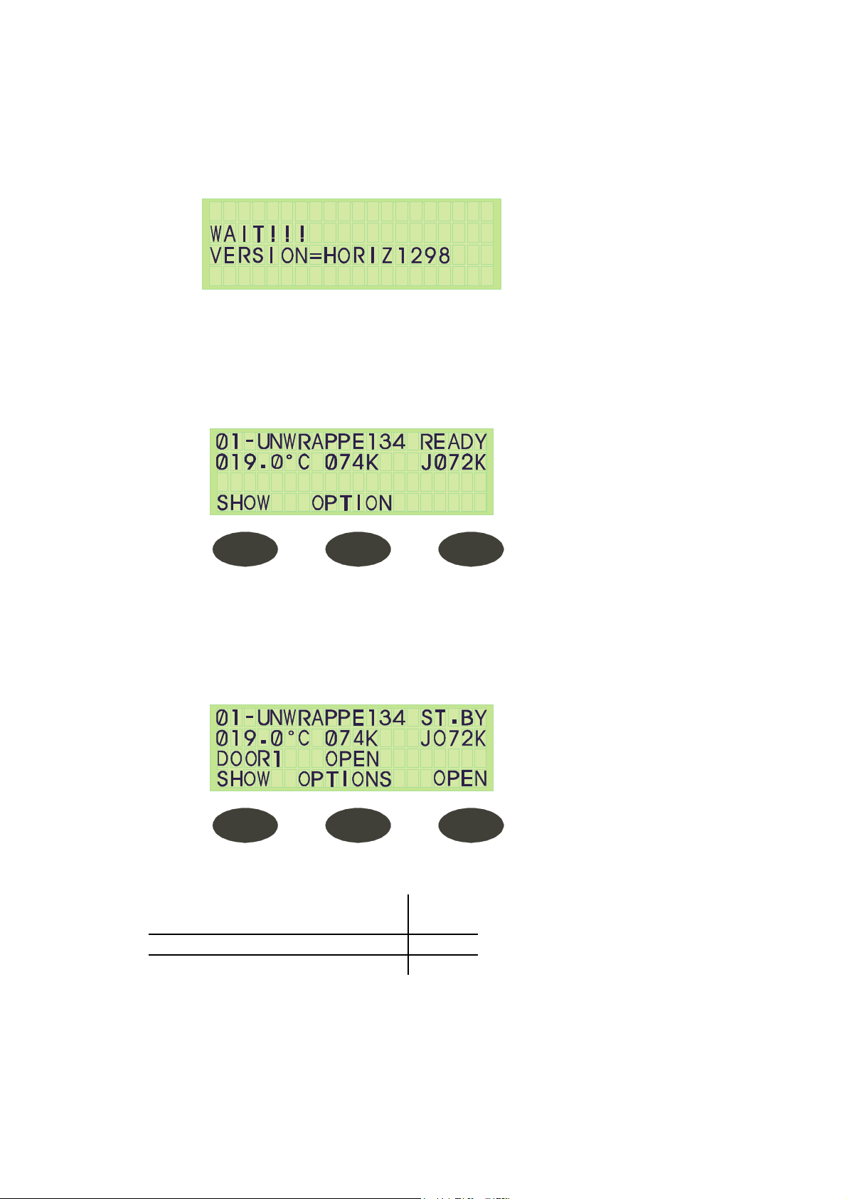
After turning ON the system, the following screen is displayed for a few seconds:
After a few seconds the Stand By screen is displayed.
This is the central screen from which all operations are performed.
It is also the “Ready” screen from where all cycles can be started, when relevant conditions
are met.
If the system is ready the display appears as follows:
If the system is not ready it will not allow you to start a cycle.
If, for example, Door1 is open when the system is turned ON, the display will warn the
operator of this in the 3rd row of the display allocated to messages, and the following screen
appears:
The 3 command keys on the Stand By screen are:
Above the left key (F1)
Show
Above the middle key (F2) Option
Above the right key (F3) Open
Page 29 of 105 pages
Page 34
4.3.2 Selecting a Cycle
A cycle can only be selected in Stand By from the Stand By / Ready screen which
displays the cycle number and name in the top row.
To select a cycle:
1. Press the UP/DN keys to change the cycle where pressing UP moves to the
next program and pressing DOWN moves to the previous program.
2. Press on a number; press key 4 to select program 4
Selecting a 2 digit cycle:
For programs with double digits (for program 10 or above), both numbers are to be
pressed within 2 seconds of each other. For example, to choose program 12, number 1
must be pressed, and within 2 seconds number 2 must be pressed.
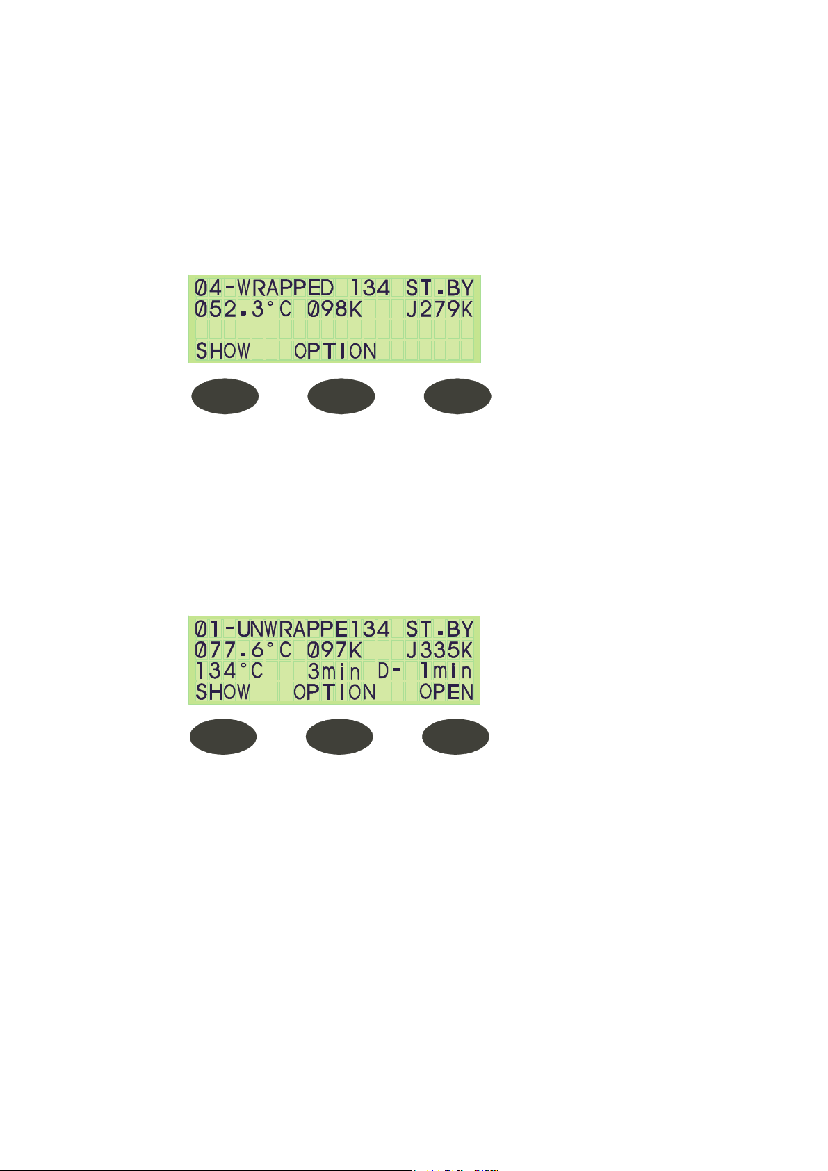
Show Parameters
After selecting the cycle, when pressing the SHOW command key the following screen
is displayed:
The message displayed in the 3rd row describes the following:
♦ The temperature; the sterilization temperature
♦ The time; the sterilization time
♦ D-Time; drying time.
This screen is displayed for 10 seconds after which it automatically returns to the ST.BY
screen.
This command key is not active for cycle 14 – Leak Test.
Page 30 of 105 pages
Page 35

Running a Cycle
Before starting a cycle, make sure to check the following:
♦ There is enough steam pressure in the jacket.
♦ There is enough air pressure for the pneumatic valves.
♦ The door is closed.
♦ There is enough water pressure for cooling, (if applicable).
♦ There is enough tap water pressure in for the operation of the ejector.
When the SETUP has been checked and the display is in the Stand By /Ready mode,
press START to run the cycle; the RUN LED lights up and the cycle is in progress.
At the end of the cycle, the LED switches OFF, and the appliance is in the Stand By
mode.
Powering ON the Reset Test
1. Turn ON the appliance.
2. Check that all the valves and outputs, including LEDs on the panel are turned
OFF.
3. Check the last illumination of the panels is turned ON.
4. Check the message – Wait!!! Version = (version name) appears on the 2
panels with the correct version.
5. Select two-digit program numbers by pressing each digit-key within 2 seconds
of each other.
6. Check that the LEDs on the panel is turned OFF, the message deleted and the
system moves to into the Stand By Mode.
In/Out Test – Design:
The system contains a stage called In/Out Test Stage. This includes all the required
elements for the In/Out Test.
The test includes:
♦ Testing all the outputs. Each output is turned ON one at a time. The output
passes to ‘ON’ for a maximum time of 15 seconds or until the UP key is
pressed.
♦ The command begins from output number 1 until 24.
♦ Testing of all the digital inputs should take a maximum time of 15 seconds for
each input. When the input is found in “0” it will show ‘ON’ on the screen.
When the input is in “1”, it will show ‘OFF’ on the screen.
♦ All the analog inputs will be displayed on the screen without a filter. As such, it
will be able to calibrate them at the time that the display is on the screen via
the PC.
♦ At the end of the stage, it will allow the In/Out Test to start afresh or to exit.
When exit is chosen, the system will initialize.
♦ Inputs for the In/Out Test require a code.
Page 31 of 105 pages
Page 36

Testing the In/Out Routine
1. Turn ON the system.
2. Press the OPTION key. The right command key will be called In/Out.
By pressing on this key, the screen displays:
Code:
3. Enter In /Out Test
Code:
4. Enter the code 2ØØ7.
The screen will display the message ‘Digital Ø1 On!!!’ Be sure that OUTØ1 is ON.
5. Press on ‘UP’, the screen displays the message ‘Digital OUTØ2 ON!!!’ Be sure
that OUTØ2 is ON.
Page 32 of 105 pages
Page 37
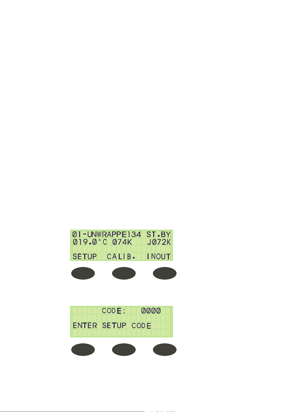
4.3.3 System Setup (Changing Parameters and Values)
Note:
♦ The system allows 15 seconds for values to be entered. If this time passes and
the panel has not been touched, the display will automatically move to the next
screen.
♦ When codes are not entered within 15 seconds, the RUN and FAIL LEDs light
and the display returns to WAIT and then to the Stand BY screen.
♦ If the code is incorrect the above will also occur.
♦ When the display shows ØØØØ and a single value (between1-9) is to be
entered, the Ø must be pressed first. The single value cannot be entered on its
own; for example, to enter the number 4, the value is entered by pressing the
Ø three times and then the number 4.
♦ When a value is to be entered, the right command key is ENTER:
♦ If the value is entered via the digital key, after the final digit is entered, the
system automatically moves to the next screen, and ENTER need not be
pressed.
♦ If the value is entered using the UP/DN keys, ENTER must always be pressed
to progress to the next screen.
The system setup includes the following functions:
Clock – Date and Time, Language, Number of Doors, Door Type and Atmospheric
Pressure
To check that the system has correctly been set, press the OPTION key on the ST.BY
screen.
The screen displayed is as follows:
Press the SETUP key. The system requests a code.
Enter the code and the display automatically moves to the next screen after the last digit
is entered.
Page 33 of 105 pages
Page 38
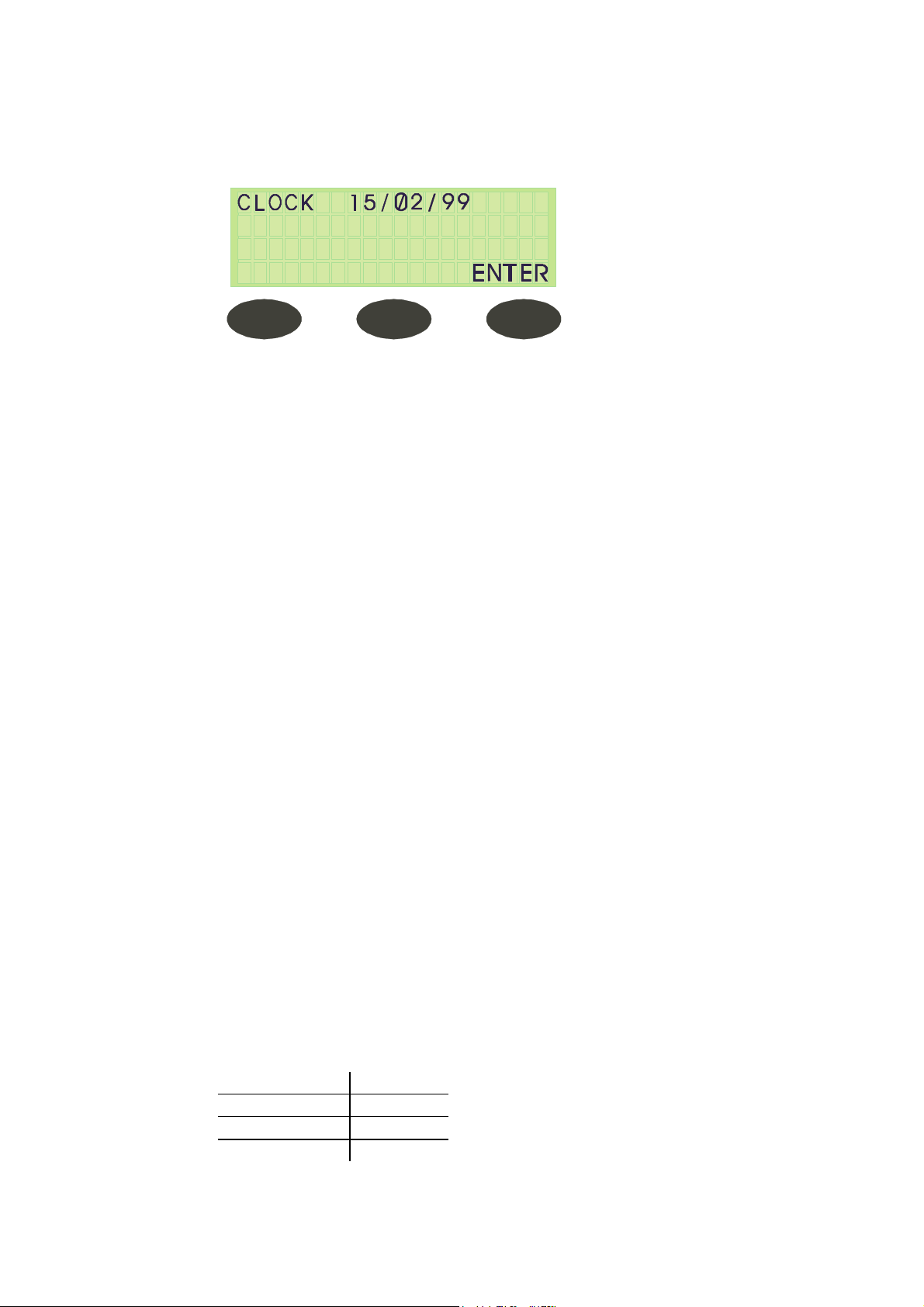
Clock
The clock first displays the date and then the time.
Date
The date is always displayed as day/month/year.
Press the UP/DN keys to change the value.
1. Press ENTER (the right command key), after selecting the desired value to
move on to the next value, i.e. the 'day value' will be underlined.
2. Press the UP/DN keys to change the value and ENTER. The 'month value' will
be underlined and the process continues.
3. To change the 'year value' to ØØ, keep pressing the DOWN key until you get
to Ø, press ENTER.
If no changes are to be made, continue pressing ENTER to skip to the next step. After
entering the 'year value', when ENTER is pressed, the display changes to the Time
display.
Time
Time is always displayed in hour/min/sec.
When entering the screen, the 'hour value' is underlined.
Press the UP/DN keys to change this value.
Press ENTER (the right command key), to move on to the 'minute value'.
Continue the process until the time is correct.
If no changes are to be made, press ENTER to move on to the 'second value'.
Pressing ENTER after the second value has been changed automatically skips to the
next screen – the Language screen.
If there are no changes to be made, continue pressing ENTER until the Language
screen is displayed.
Language (Option)
4 popular languages have been specified with Latin letters only: English, German,
French and Spanish.
This screen is relevant if using different languages.
The right command key is ENTER.
If English is being used, leave the code at Ø and press ENTER to move on to the next
screen – Doors Number.
If the language requires to be changed, press the appropriate number as specified
below and then press ENTER.
English Ø
German 1
French 2
Spanish 3
Page 34 of 105 pages
Page 39
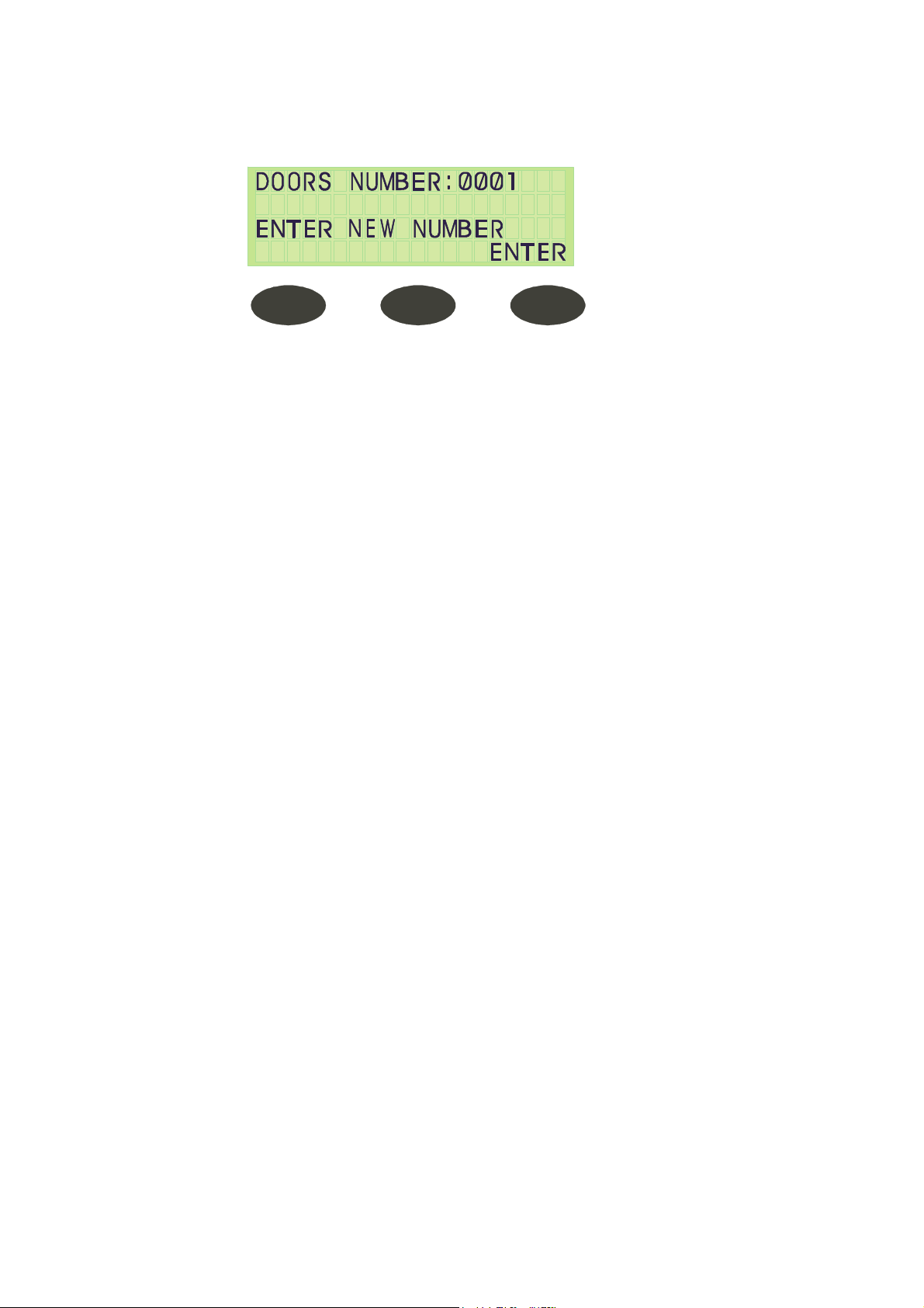
Doors Number
After entering the language, the following message is displayed:
This autoclave has one door, press ØØØ1. Press ENTER, and the system moves to the
next screen.
Door Type
There are 3 different door types for autoclaves – Manual Door, Automatic Hinged Door,
or Automatic Sliding (horizontal or vertical) Door.
In this autoclave, the door is a manual hinged door; the door type is (ØØØØ). Enter
these values either through the UP/DN keys and then press ENTER, or enter the digits
whereby the screen will automatically progress to the next display after entering the
fourth digit.
Atmospheric Pressure
The standard atmospheric pressure at Sea Level is 14.5psi. For every 1000ft. above sea
level, the atmospheric pressure drops 0.45psi, and for every 1000ft below sea level, the
atmospheric pressure increases 0.45psi.
(The standard atmospheric pressure at the sea level is 100 kPa and for every 100m
above sea level, the atmospheric pressure drops by 1kPa, and for every 100m below
sea level, the atmospheric pressure increases by 1kPa.)
When the door of the autoclave is open then set Atm. Pres. Parameter is entered into
the program memory and will serve as reference for correct pressure control and
monitoring.
If pressure is set correctly, then press ENTER and the next screen appears. If pressure
needs to be altered, this may be done either through the digital key or the UP/DN keys.
F – 0 Mode
This mode enables F – 0 calculations, the processing being based on data fed by two
temperature sensors. One mounted in chamber and one on the condensate pipeline.
The F - 0 calculations is performed for cycles with sterilization temperatures in the range
of 215ºF - 273ºF (101ºC–134ºC), especially used in programs 9–12.
F – 0 = 0 (unable)
F – 1 = total heating time + total cycle time + cooling time.
F – 2 = compensate the difference between heating time, cooling time and exhaust.
Calculates using factor 1.5 of the total accumulated heating and cooling time and
converts that into the equivalent sterilization time.
Temp F – 0 = determines the temperature at which F – 0 calculations should begin.
Page 35 of 105 pages
Page 40
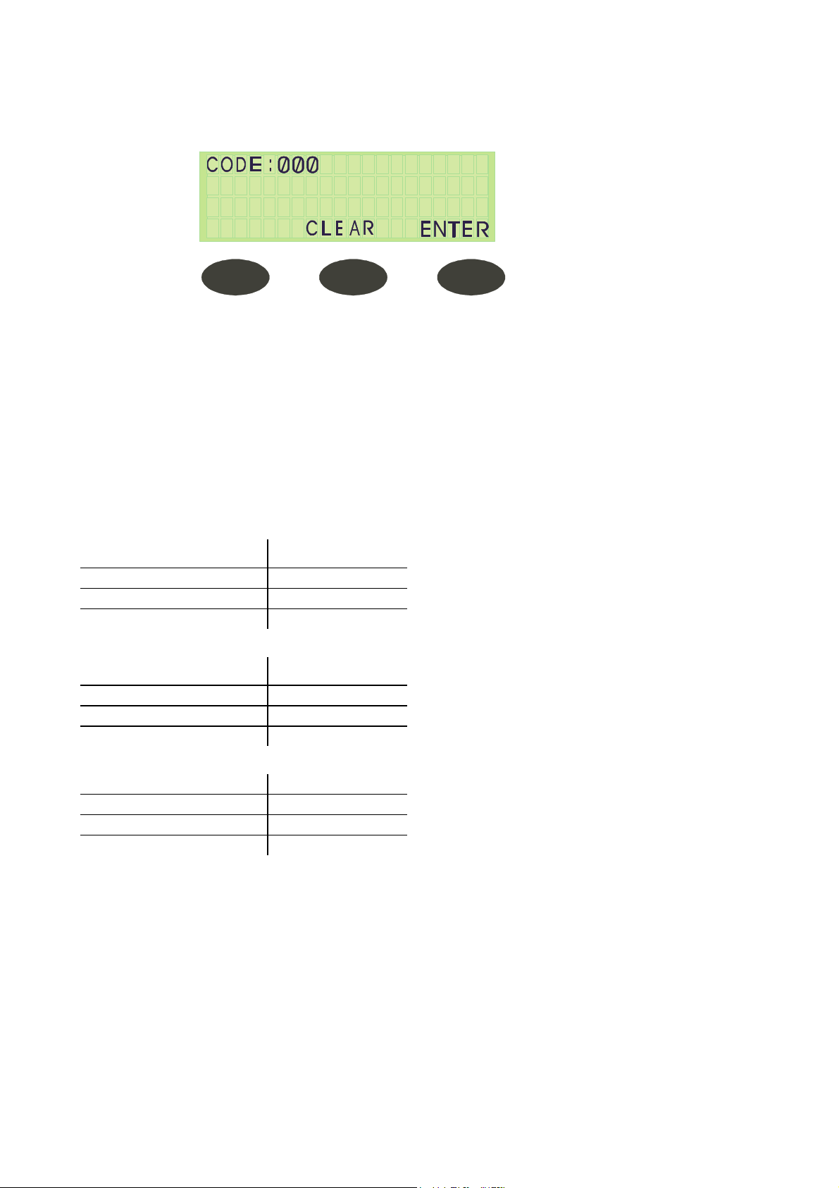
4.3.4 Changing Cycle Parameters
The screen that allows for parametric changes appears as follows:
1. Press CLEAR or ENTER before entering the code to return to the Stand By
screen; the RUN & FAIL LEDs are lit.
2. Enter the correct code via the UP/DN keys.
3. Press ENTER to proceed to the next screen.
4. Press the UP/DN keys to change all parametric values.
Cycle Setup Parameters
CODE 1 OR 11 PARAMETERS
STE Temp – Required sterilization temperature for the process
Entry code 1
Resolution 1º
Minimum value 221 ºF (105ºC)
Maximum value 278 ºF (137ºC)
STE Time – Required sterilization time for the process
Entry code 1
Resolution 1 minute
Minimum value 1 minute
Maximum value 99 minutes
Dry Time – Required drying time for the process
Entry code 1
Resolution 1 minute
Minimum value Ø minutes
Maximum value 99 minutes
Page 36 of 105 pages
Page 41

Heat T.O. – Maximum time for heating the chamber for starting sterilization
When the duration of the heating stage is longer than Heat T.O., the program will
collapse with the message ‘Low Heat’.
Entry code 11
Resolution 1 minute
Minimum value 20 minutes
Maximum value 60 minutes
Ex Mode – The method for exhausting the steam at the end of the process
Entry code 11
Ex Mode
Fast Ex 1
N.A. 2
Slow Ex. (waste) 3
Slow Ex. (liquids) 4
Cooling with compressed air 5
Cooling with water circulation 6
EndTemp – Ending Temperature (Exhaust Stage)
Defines the temperature at which the process ends for opening the door.
Entry code 11
Resolution 1º
Minimum value 104 ºF (40ºC)
Maximum value 278 ºF (137ºC)
PulsNum. – No. of pulses in the pre-vacuum stage
Entry code 11
Resolution 1
Minimum value 1
Maximum value 10
VacDip1 – Vacuum value in the first pulse
Defines the vacuum value in pulse No.1 of the pre-vacuum stage
Entry code 11
Resolution 0.1 psi (1 kPa)
Minimum value 0.15 psia (1 kPa)
Maximum value 10.8 psia (75 kPa)
Page 37 of 105 pages
Page 42

VacDip2 – Vacuum value in the remaining pulses
This value defines the vacuum in the remaining pulses in the pre-vacuum stage (not just
pulse no. 2)
Entry code 11
Resolution 0.1 psi
Minimum value 0.15 psia (1kPa)
Maximum value 10.8 psia (75kPa)
VacTime1 – Waiting time in the first pulse
In the pre-vacuum stage, in the first pulse after arriving at VacDip1, there is a waiting
time known as VacTime1 (in seconds).
This delay occurs so that air removal and vacuuming can continue.
Entry code 11
Resolution 1 second
Minimum value 3 seconds
Maximum value 1800 seconds (30 minutes)
VacTime2 – Waiting time for the remaining pulses
For the remaining pulses (following pulse no.1) in the pre-vacuum stage, after arriving at
the VacDip2 stage there is a time delay known as VacTime2 (in seconds).
Entry code 11
Resolution 1 second
Minimum value 3 seconds
Maximum value 1800 seconds (30 minutes)
WtrTime – Time for entering the water into the generator after the electrode is
touching the water.
This value defines the time (in seconds) during which the water pump continues to work
and enter water to the steam generator after the upper electrode touches water.
This is done to prevent a situation where right after the electrode touches water, the
pump immediately stops operating.
Entry code 11
Minimum value Ø second
Maximum value 90 seconds
Page 38 of 105 pages
Page 43

LimitP add – Adding pressure to the maximum pressure
This value defines the addition to the maximum pressure, computed to the jacket
control.
For example, when the desired temperature is 134ºC (273ºF) the maximum
temperature maintained in the jacket will be adjusted to a temperature of 137ºC (i.e.
332kPa) - 278 ºF (48 psi)
When this pressure is not enough, it can be increased by changing the values of the
LimitP add.
If the parameter value remains Ø, the maximum pressure in the jacket will be 32.4 psig,
however if this value will be 10, the maximum pressure will be 35 psig.
Entry code 11
Resolution 0.5 psi (1 kPa)
Minimum value ØkPa/psia
Maximum value 4.35 psia (30 kPa)
PulsPres1 – The pressure in pulse no.1 in the pre-vacuum stage
This defines the first pulse pressure in the pre-vacuum stage. If it is defined as 100kPa,
the system will not enter steam into the chamber, however; the ejector will immediately
start operating to create a vacuum.
If the value is defined over 100kPa, the system will open the steam valve to the chamber
until the desired pressure is reached.
Entry code 11
Resolution 1 psi (5kPa)
Minimum value 14.5 psia (100 kPa)
Maximum value 44 psia (300 kPa)
PulsPres2 – The pressure in pulse 2 and onwards in the pre-vacuum stage
After the completion of pulse no.1, the system will enter steam by the defined value in
pulse press.
Entry code 11
Resolution 1 psi (5 kPa)
Minimum value 14.5 psia (100 kPa)
Maximum value 44 psia (300 kPa)
CODE 13 - PARAMETER
ReqPrs+ - The addition to the required pressure for sterilization
This parameter sets the pressure point maintained during the sterilization stage in the
following manner:
If the desired temperature is 273°F (134ºC), the required pressure (from the tables) is
44.2 psi (305kPa).
When the ReqPrs+ is Ø, the system pressure will be maintained at 44.2 psi (305kPa)
during the sterilization stage. When the Reqprs+ equals 0.5 psi (5kPa), the system will
be maintained at 44.9 psi (310kPa) in the sterilization stage. It is advised to work with a
value of 0.5 psia (7kPa).
Entry code 13
Resolution 0.1 psi (1 kPa)
Minimum value 0.1 psia (2 kPa)
Maximum value 4 psia (20 kPa)
Page 39 of 105 pages
Page 44

Select PT100
There are 3 temperature sensors that regulate cycles:
1. Sensor 1 & 2: — in the condensate line: PT100 – No. 1 & 2
2. Sensor3: — in the chamber: PT 100 – No. 3
3. Sensor 5: — in the cooling drain: PT100 – No. 5
This is the final parameter under Code 13. Pressing ENTER returns the display to the
ST.BY screen.
Entry code 13
Resolution 1
Minimum value 1
Maximum value 5
Stay Time - Delay time between heating and sterilization
This parameter allows partial entry to the sterilization stage with a reduction of the
overshoot and the reduction difference between the different sensors that are entered
into the chamber for control or validation.
In the Heating Stage the system will stop heating before entering Sterilization according
to the STAY TIME value. When this value is set to 2 minutes, the system will stop 2ºC
before entering sterilization and will proceed at a rate of 1ºC/min during the STAY TIME.
Entry code 11
Resolution 1 minute
Minimum value Ø minute
Maximum value 15 minutes
This is the final parameter under Code 11. After pressing ENTER the display will return
to the ST.BY screen
Dry Vac. - Dry Vac. =0;
Entry code 11
Resolution 1 (Mode)
Minimum value Ø
Maximum value 90
Bio Cycle
Entry code 33
Resolution 1 (Mode)
Minimum value Ø
Maximum value 1
Air Detector
Entry code 33
Resolution 1 (Mode)
Minimum value Ø
Maximum value 1
Page 40 of 105 pages
Page 45
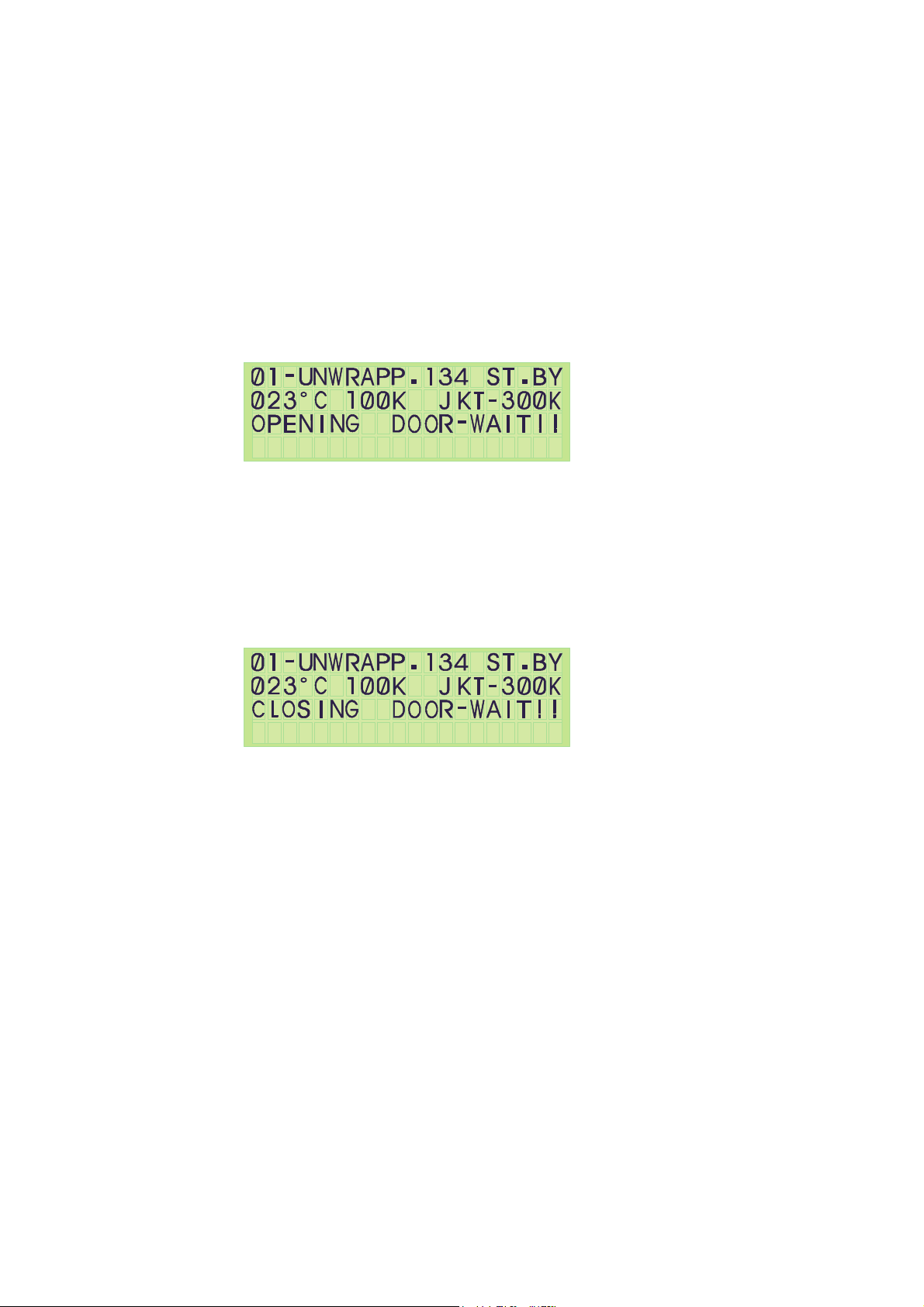
4.3.5 Door Display Function
(Applicable only for automatic doors)
Displays when Opening or Closing the Doors
Opening an Automatic Door
During the process of opening an automatic door, the message OPENING DOOR –
WAIT will appear in the 3rd row.
Closing an Automatic Door
During the process of closing an automatic door, the message CLOSING DOOR – WAIT
will appear in the 3rd row.
If the pressure in the chamber is higher than 2.7 psig (115 kPa) it will not be possible to
open the door.
Page 41 of 105 pages
Page 46
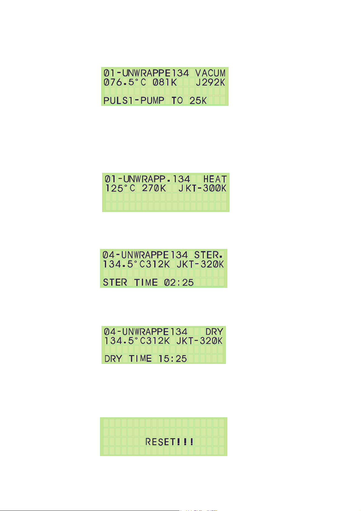
4.3.6 Display during a Cycle
Display during the Pre-Vacuum Stage
When the cycle passes to the Heat stage the steam enters the system, in place of
‘PUMP TO 25K’, it will display ‘HEAT TO 160K’.
When the cycle passes to the Exhaust stage,’ it will display ‘EXH TO 100K’.
Display during the Heating Stage
Display during the Sterilization Stage
Display during the Drying Stage
Help:
If at any stage there is a problem, the system can be turned OFF at the power switch.
Turn ON the power again, while pressing the STOP key until you hear a long buzz. After
loading the screen, the screen lights with the message below.
The display returns to the ST.BY screen and you can continue from there.
Page 42 of 105 pages
Page 47

5. PRINTER
5.1 Printer Output
The autoclave is equipped with a character printer, which prints a detailed history of
each cycle performed by the instrument (for the record or for subsequent consideration).
The printing is made on plain paper with 24 characters per line and contains the
following information:
♦ Software version
♦ Real time
♦ Selected program
♦ Sterilization pressure
♦ Sterilization temperature
♦ Sterilization time
♦ Summary of performed cycle and identification hints.
When the sterilization cycle begins the printer starts printing the above data.
After the preliminary printing, the autoclave starts performing the sequence of operations
of the cycle. The measured values of temperature and pressure are printed at fixed time
intervals, according to the phase of the process, as shown in the table below.
The data is printed from the bottom up, beginning with the date and ending with “O.K.”
for a complete cycle or “FAIL” for an aborted cycle.
For an example of a typical printout, see next page.
Page 43 of 105 pages
Page 48

PRINTER OUTPUT DESCRIPTION
Autoclave: 2912082 Autoclave serial no.
Name : __-------- Name of the operator to be filled in .
Load #: 0030 To be filled in manually by the operator.
21/05/2010 13:45:16 Date and time the cycle ended
F11:30 187.6ºF 0.13 In If cycle fails, conditions at time of failure.
CYCLE FAILED! ! ! Message displayed if cycle fails.
Manual Stop - 03 If operator presses the manual stop button.
H11:28 274.5ºF 32psi
H10:08 273.3ºF 32psi
H06:04 270.5ºF 30psi
H02:00 245ºF 21 psi
H03:00 161.1ºF 23.5 In
V00:22 180.3ºF 23.5 In
The time, temperature and pressure during
sterilization.
The time, temperature and pressure during the
heating stage.
The time, temperature and pressure during the
heating stage.
The time, temperature and pressure during the
heating stage.
The time, temperature and pressure during the
heating stage.
The time, temperature and pressure during air
removal (vacuum).
Exhaust mode: 1 Exhaust mode: fast exhaust and process ends..
Dry time : 015 min Drying time of the selected program
Ster time: 007.0 min. Preset sterilization time of the selected program.
Ster Temp: 274ºF
Sterilization temperature in chamber for selected
program.
Cycle: 07 wrapped Selected program: wrapped Instruments.
21/05/2010 13:29:31 Date/month/year time/min./sec.
Version = Horiz US3M7 Eje Number and version of the software program.
Legend
V - Vacuum stage
S - Sterilization stage
E - Exhaust stage
H - Heating stage
F - Fail
Note:
The process is printed from the bottom to the top – starting with version.
Page 44 of 105 pages
Page 49

5.2 Printer Operation
Caution!
Do not perform the following operation, since they may be damage the printer.
1. Do not carry out blank printing without recording paper and no ink ribbon in the
unit, this may damage the printing head.
2. Do not drop any foreign subjects as paper clips, or splits pins, etc. into the
printer unit.
3. Do not pull the paper in printer forcibly by hand or pull the paper in opposite
way to paper feed direction.
4. Replace ink ribbon cassette before the ink of this ribbon runs out completely.
Ribbon damaged by excess use may result in printing problems. Do not apply
ink on this ribbon cassette.
Opening/Closing the Front Panel
1. Press, with your finger, on the left side of the front panel and pull it forward
when the lock is released. It opens about 180° around the fixed axis.
2. For closing, press the front panel, tightly close it until a click sound is heard.
Also, confirm, on closing, that paper is not jammed.
Opening/Closing the Ribbon Cover
1. When paper is out of the front cover, cut it off.
2. Press, with your finger, on the dent on the left side of the ribbon cover and pull
it forward. It opens, approximately, 180° around the fixed axis.
3. For closing, press the ribbon cover and close it tightly.
Paper Feeding
1. With the LF switch pressed once, paper is fed by one line.
2. Paper is fed continuously while it is continuously pressed.
3. To feed paper, do not pull it forcibly. Use the LF switch.
4. During pressing the LF switch, the data can not be received.
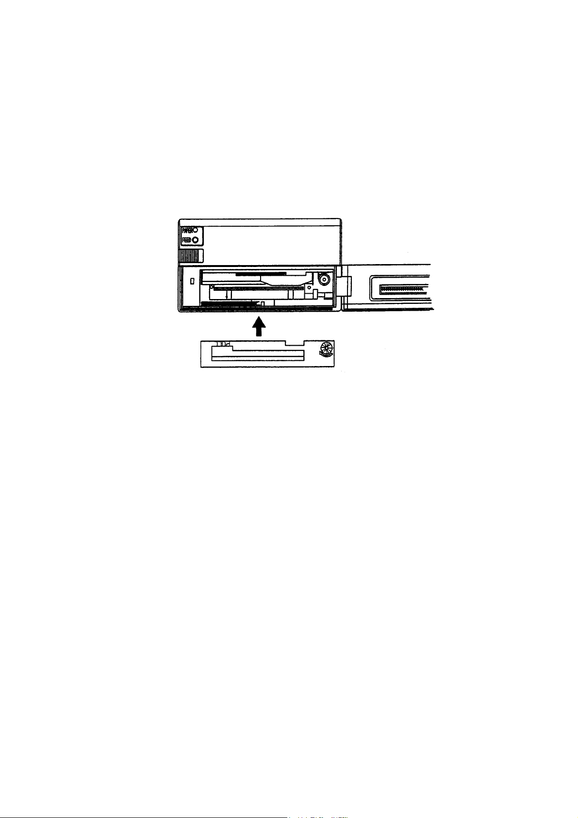
Replacing Ribbon Cassette
1. Turn off the power.
2. Open the ribbon cover.
3. In case the paper is out from front cover, cut the paper or remove this paper.
4. Remove the old ribbon cassette by pulling it out by the edge market with
“PULL”.
5. Insert ribbon between the printing head and the platen, verifying that the new
ribbon cassette is in the correct direction. Press cassette down from the knob
side.
6. Turn the ribbon cassette knob clockwise (see arrow) to cancel slack.
Page 45 of 105 pages
Page 50
Note:
a. In case the ribbon cassette is kept in the printer to long, the printing paper may
be contaminated.
b. Continuous printing under low temperature may result in light-color characters
due to the characteristics of the ink.
c. Do not attempt to print without the ribbon cassette since this may damage the
printer’s head.
d. Replace ribbon cassette before wearing out completely.
e. Use original ribbon cassette.
5.3 Printing Paper
The Paper Roll
Before inserting paper into the printer verify that the beginning of roll paper to the inner
core must be as follows.
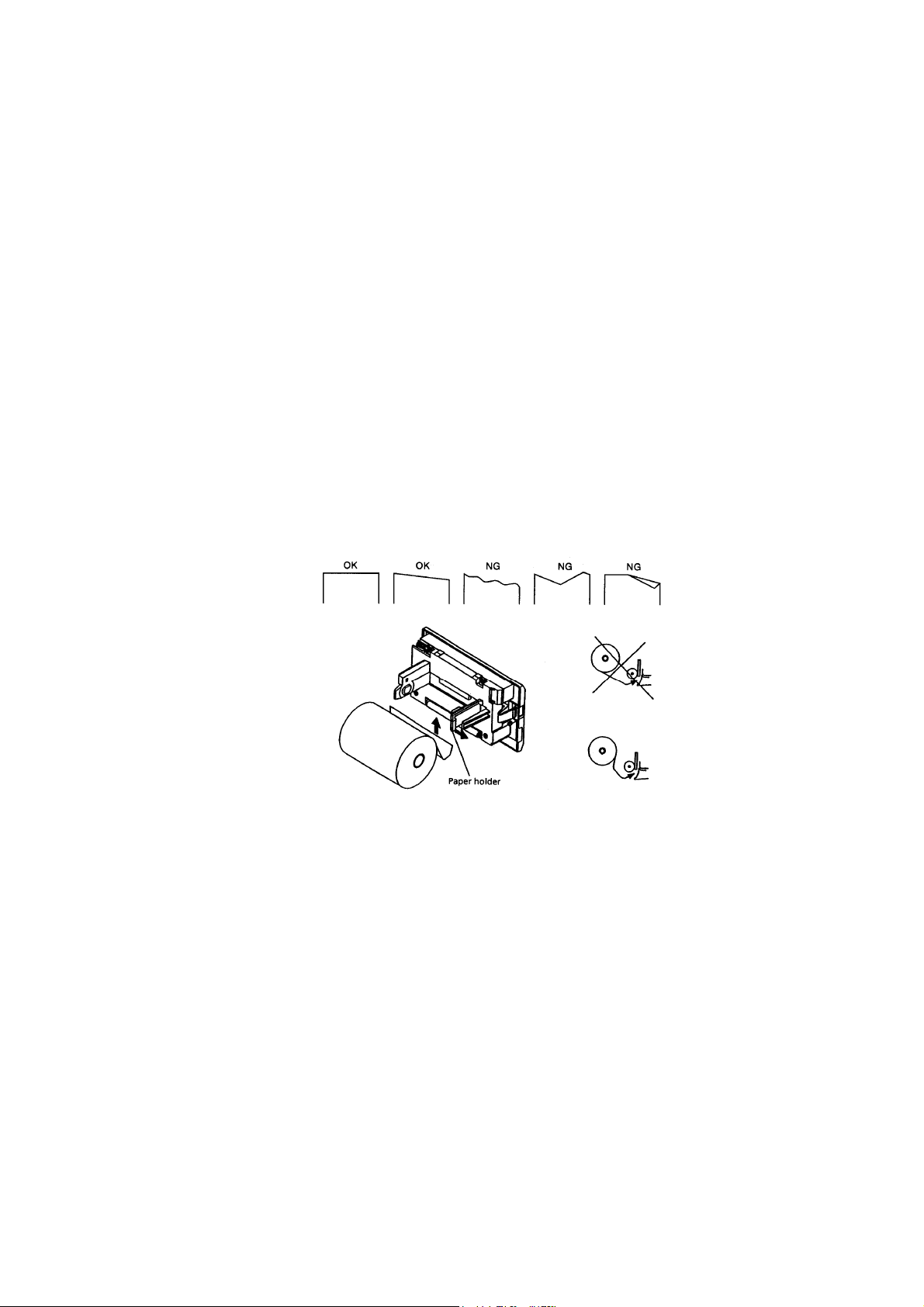
1. No folds. Paper must be rolled on the inner core
2. No flap
3. Do not stick the paper to the core. (If an inner core is available)
Recommended paper:
One ply paper 45 ~55 Kg/1000 pcs/1091 x 788 mm
2 ply paper No carbon paper Original paper (34 Kg paper)+copy paper 1 pcs (34
Kg paper)
Total thickness 0.13 mm or less
Replacing the Paper Roll
1. Open the front cover.
2. Press outwards the arms of the paper-roll clip (see drawing) and remove the
roll’s core. Remove, at this time, excessive paper by using the LF switch.
3. Cut the edge of the Printing Paper according to the following drawing.
4. Insert the new paper into the paper-roll clip of the printer mechanism.
Page 46 of 105 pages
Page 51
When auto-loading function is specified, paper is loaded automatically.
When auto-loading function is not specified, push the LF switch until the paper
enters the printer mechanism.
5. Press slightly the paper holder in the direction marked with an arrow (see
drawing) and insert paper roll. Verify that the paper holder holds the roll’s core.
6. After canceling the slack of the printing paper, close the front panel.
7. After setting the paper, press LF switch once. The printer turns to data input
printing mode.
Note:
a. Verify that the paper winding direction is correct.
b. Do not replace paper while the autoclave is operating.
c. Do not pull the paper in reverse direction of paper feed. This may damage the
printing head.
d. If the paper strip is not perpendicular to the printer, the printer may be jammed.
In case the printer is jammed, turn OFF the power switch immediately and pull
out, slowly, the excessive paper. Pulling the paper must be done perpendicular
to the printing head.
Paper Near End
When the paper roll is near the end, the paper-near-end is detected and printing is
stopped. Power supply to the printing solenoid and motor is immediately stopped and
BUSY PE signals are displayed.
When data still exists in the input buffer, the remaining data in the buffer is printed
before stopping.
Discharge remaining paper with the LF switch, set new paper and push the LF switch.
Then normal print mode is created after cancellation of BUSY and PE output.
This function can be selected by Dip-Switch setting.
Page 47 of 105 pages
Page 52

Paper End
This feature detects that there is no paper in the printer. When there is no printing paper,
printing stops and BUSY and PE signal are displayed.
Printing is also stopped in case data remains in the input buffer.
Install a new paper roll as described in para. 5.5 Then BUSY PE is canceled.
When auto loading function is available, printer automatically feeds recording paper a
few lines by inserting the recording paper into the paper inlet.
5.4 Mechanical Alarm
When trouble in the mechanism results in locking of the motor, power supply to the
printing solenoid and motor is stopped and BUSY signal as well as FAULT signal are
displayed.
To recover from alarm state, after correcting causes for the malfunction, either re-supply
power or input RESET signals.
For severe trouble, turn power OFF and call for service.
5.5 Auto Loading Function
This printer is equipped with a function that can automatically load paper. With paper
inserted, it is automatically fed a few lines. When printing paper is not perpendicular to
the printing head or not properly fed, take out paper gently and insert it once again.
If not using this function, cancel this with the Dip-Switch. Paper insertion is, then,
performed with the LF switch.
After paper is inserted, with the LF switch pressed and detached, print ready state is
created.
Page 48 of 105 pages
Page 53
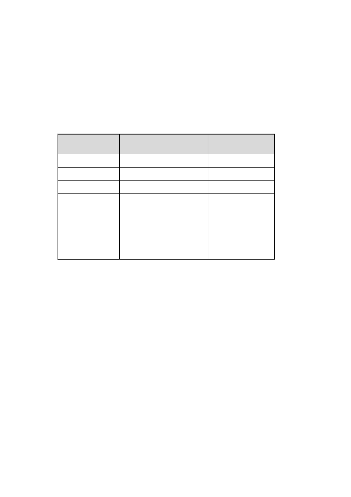
6. STERILIZATION PROGRAMS
6.1 Program Descriptions
The autoclave is equipped with 12 programmable sterilization programs and two test
programs. The test programs are pre-set by the manufacturer in such a way, that their
parameters are not changeable.
Following are the names, relevant programs with related temperatures of the 12
sterilization cycles and 2 test programs.
Cycle no. Program Temp ºF
1, 2, 3 Un-wrapped 270
4, Un-Wrapped 270
5, 6 Wrapped 270
7 Wrapped 275
8 Wrapped 250
9, 10, 11, 12 Slow exhaust 250
13 B&D test 274
14 Leak test —
Page 49 of 105 pages
Page 54
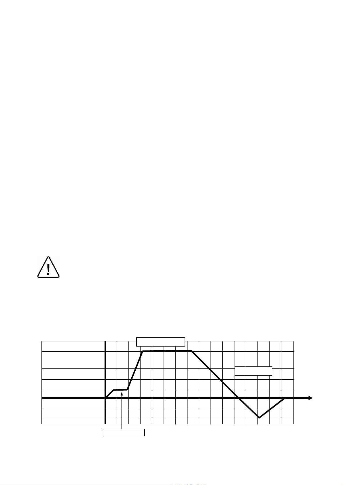
Programs 1, 2, 3, Un-wrapped Goods, With Purge (Process Sample)
These programs are intended for un-wrapped rigid (like instruments) and other goods,
which their manufacturers declare their compliance with the following sterilization
conditions:
♦ Sterilization temperature: 270ºF
♦ Sterilization time: 3 min
♦ Purge time 30 sec
Performance Description:
Saturated (controlled) steam is introduced into the chamber to the required sterilization
temperature after 30 seconds of purge.
Sterilization is controlled in such a way that the sterilization temperature will not drop
below the required temperature, neither will increase by more than 3.4ºF. The saturated
steam conditions are controlled in such a way that the fluctuation of pressure does not
allow a drop below 0.14 psi, neither an increase of 0.44 psi above the high limit of the
Ste. Temperature.
Fast exhaust is performed by rapidly discharging the pressure from the chamber. The
ejector is activated until the pressure drops to 7.39 inHg.
Pressure equilibration enables the door to be opened. Air is introduced into the
chamber through a microbiological filter until equilibrium is reached with atmospheric
pressure.
Note:
The temperature of the chamber must be below the end sterilization temperature
and the pressure must be below 2.0 psig to enable the door to be opened.
Caution!
Care should be taken to preserve the sterility of unwrapped instruments in a nonsterile environment.
Programs 1, 2, 3, Un-wrapped Goods, With Purge (Process Sample)
270°F/ ~ 27.1 psig
270°F 3 min
8.5 psig
2.2 psig
0 psig
14.7 inHg
7.4 inHg
0 inHg
Ex Mode 1
Purge 30 sec
Page 50 of 105 pages
Page 55
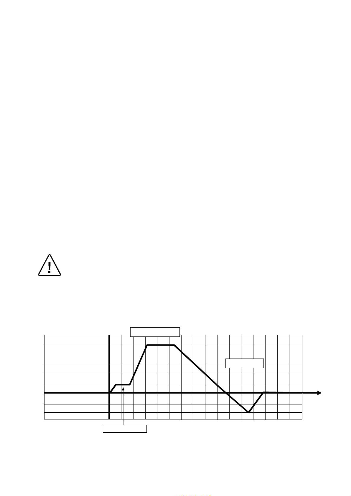
Program 4 for Un-wrapped Goods, With Purge (Process Sample)
This program is intended for un-wrapped rigid (like instruments) and other goods, which
their manufacturers declare their compliance with the following sterilization conditions:
♦ Sterilization temperature: 270ºF
♦ Sterilization time: 10 min
♦ Purge time 30 sec
Performance Description:
Saturated (controlled) steam is introduced into the chamber to the required sterilization
temperature after 30 seconds of purge.
Sterilization is controlled in such a way that the sterilization temperature will not drop
below the required temperature, neither will increase by more than 3.4ºF. The saturated
steam conditions are controlled in such a way that the fluctuation of pressure does not
allow a drop below 0.14 psi, neither an increase of 0.44 psi above the high limit of the
Ste. Temperature.
Fast exhaust is performed by rapidly discharging the pressure from the chamber. The
ejector is activated until the pressure drops to 7.39 inHg.
Pressure equilibration enables the door to be opened. Air is introduced into the
chamber through a microbiological filter until equilibrium is reached with atmospheric
pressure.
Note:
The temperature of the chamber must be below the end sterilization temperature
and the pressure must be below 2.0 psig to enable the door to be opened.
Caution!
Care should be taken to preserve the sterility of unwrapped instruments in a nonsterile environment.
Program 4 for Un-wrapped Goods, With Purge (Process Sample)
270°F/ ~ 27.1 psig
270°F 10 min
8.5 psig
2.2 psig
0 psig
Ex Mode 1
14.7 inHg
7.4 inHg
0 inHg
Purge 30 sec
Page 51 of 105 pages
Page 56
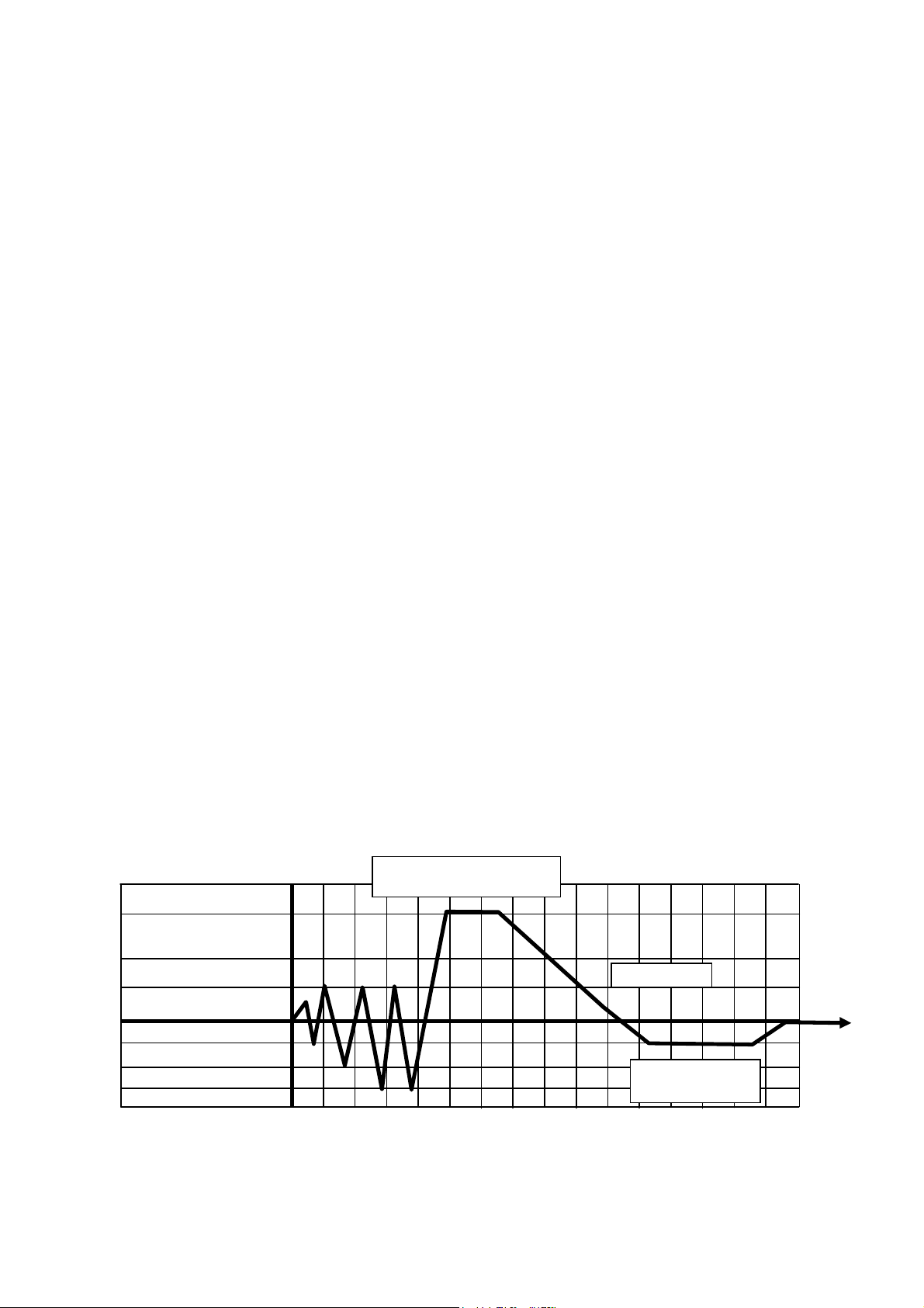
Programs 5, 6 - for Wrapped goods 270ºF (Process Sample)
These programs are intended for wrapped materials (like instruments), porous loads and
other goods, which their manufacturers declare their compliance with the following
sterilization conditions:
♦ Sterilization temperature 270ºF
♦ Sterilization time 4 min for program 5 (10 min for program 6)
♦ Drying time 30 min for program 5 (20 min for program 6)
Performance Description:
Residual air is displaced by 4 vacuum pulses (down to 7.4inHg) and 3 steam pulses up
to 8.5 psig. The 4th vacuum pulse is followed by the introduction of saturated (controlled)
steam into the chamber to the required sterilization temperature.
Sterilization is controlled in a way that the sterilization temperature will not drop below
the required temperature, neither increase by more than 3.4ºF. The saturated steam
conditions are controlled in a way that the fluctuation of pressure does not allow a drop
below 0.14 psi or an increase of over 0.44 psi, above the high limit of the Ste.
Temperature.
Fast exhaust is performed by rapidly discharging the pressure from the chamber. The
ejector is activated until the pressure drops to 7.4 inHg.
Drying is achieved by evacuating the vapor from the chamber in an "under-pressure"
phase for a period of 30 min for program 5, and 20 min for program 6).
Pressure equilibration enables the door to be opened. Air is introduced into the
chamber through a microbiological filter until equilibrium is reached with atmospheric
pressure.
Note:
The temperature of the chamber must be below the end sterilization temperature
in the range of 140ºF - 212ºF and the pressure must be below 2.0 psig to enable
the door to be opened.
Important:
In order to obtain good sterilization results, dry time is essential.
Programs 5, 6 - for Wrapped Goods 270ºF (Process Sample)
270°F 4 min (Prog 5)
270°F 10 min (Prog 6)
274°F/ ~ 27.1 psig
13.3 psig
0 psig
7.3 inHg
5.0 inHg
3.7 inHg
0 inHg
Ex Mode 1
30 min (Prog 5)
20 min (Prog 6)
Page 52 of 105 pages
Page 57
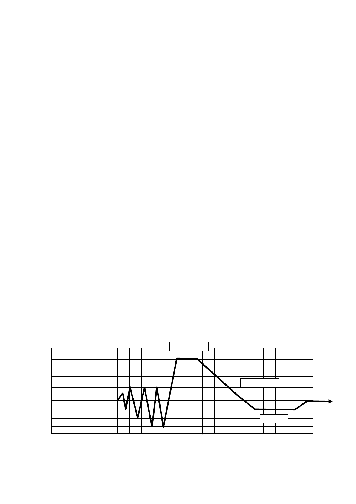
Program 7 - for Wrapped Goods 275ºF (Process Sample)
This program is intended for wrapped materials (like instruments), porous loads and
other goods, which their manufacturers declare their compliance with the following
sterilization conditions:
♦ Sterilization temperature 275ºF
♦ Sterilization time 3 min
♦ Drying time 20 min
Performance Description:
Residual air is displaced by 4 vacuum pulses (down to 7.4inHg) and 3 steam pulses up
to 8.5 psig. The 4th vacuum pulse is followed by the introduction of saturated (controlled)
steam into the chamber to the required sterilization temperature.
Sterilization is controlled in a way that the sterilization temperature will not drop below
the required temperature; neither will increase by more than 3.4ºF. The saturated steam
conditions are controlled in such a way that the fluctuation of pressure does not allow a
drop below 0.14 psi, neither an increase of 0.44 psi above the high limit of the Ste.
Temperature.
Fast exhaust is performed by rapidly discharging the pressure from the chamber. The
ejector is activated until the pressure drops to 7.4 inHg.
Drying is achieved by evacuating the vapor from the chamber in an "under-pressure"
phase for a period of 20 minutes.
Pressure equilibration enables the door to be opened. Air is introduced into the
chamber through a microbiological filter until equilibrium is reached with atmospheric
pressure.
Note:
The temperature of the chamber must be below the end sterilization temperature
in the range of 140ºF - 212ºF and the pressure must be below 2.0 psig to enable
the door to be opened.
Important:
In order to obtain good sterilization results, dry time is essential.
Program 7 - for Wrapped Goods 275ºF (Process Sample)
275°F 3 min
274°F/ ~ 27.1 psig
13.3 psig
0 psig
7.3 inHg
5.0 inHg
3.7 inHg
0 inHg
Ex Mode 1
20 min
Page 53 of 105 pages
Page 58
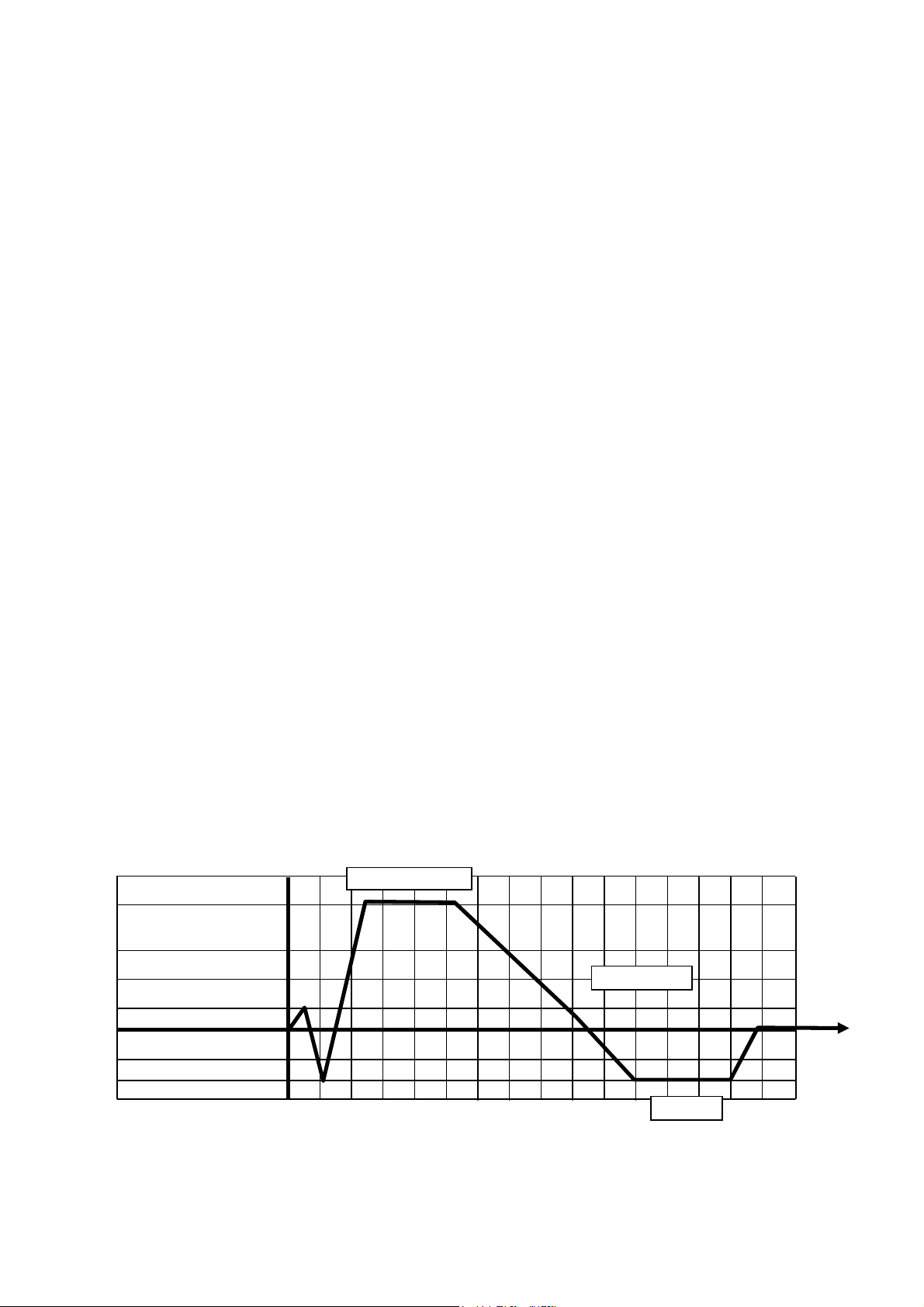
Program 8 - for Wrapped Materials 250ºF (Process Sample)
This program is intended for wrapped materials (like instruments), porous loads and
other goods, which their manufacturers declare their compliance with the following
sterilization conditions:
♦ Sterilization temperature 250ºF
♦ Sterilization time 30 min
♦ Drying time 45 min
Performance Description:
Residual air is displaced by 1 vacuum pulse (down to 7.4inHg). The vacuum pulse is
followed by the introduction of saturated (controlled) steam into the chamber to the
required sterilization temperature.
Sterilization is controlled in a way that the sterilization temperature will not drop below
the required temperature; neither will increase by more than 3.4ºF. The saturated steam
conditions are controlled in such a way that the fluctuation of pressure does not allow a
drop below 0.14 psi, nor an increase of 0.44 psi above the high limit of the Ste.
Temperature.
Fast exhaust is performed by rapidly discharging the pressure from the chamber. The
ejector is activated to allow the chamber to reach the "under-pressure" phase for drying.
Drying is achieved by evacuating the vapor from the chamber in an "under-pressure"
phase for a period of 45 minutes.
Pressure equilibration enables the opening of the door. Air is introduced into the
chamber through a microbiological filter until equilibrium is reached with atmospheric
pressure.
Note:
The temperature of the chamber must be below the end sterilization temperature
in the range of 140ºF - 212ºF, and the pressure must be below 2.0 psig to
enable the door to be opened.
Important:
In order to obtain good sterilization results, dry time is essential.
Program 8 - for Wrapped Materials 250ºF (Process Sample)
250°F/ ~ 15.3 psig
8.5 psig
2.2 psig
0 psig
250°F 30 min
Ex Mode 1
14.7 inHg
7.4 inHg
0 inHg
45 min
Page 54 of 105 pages
Page 59
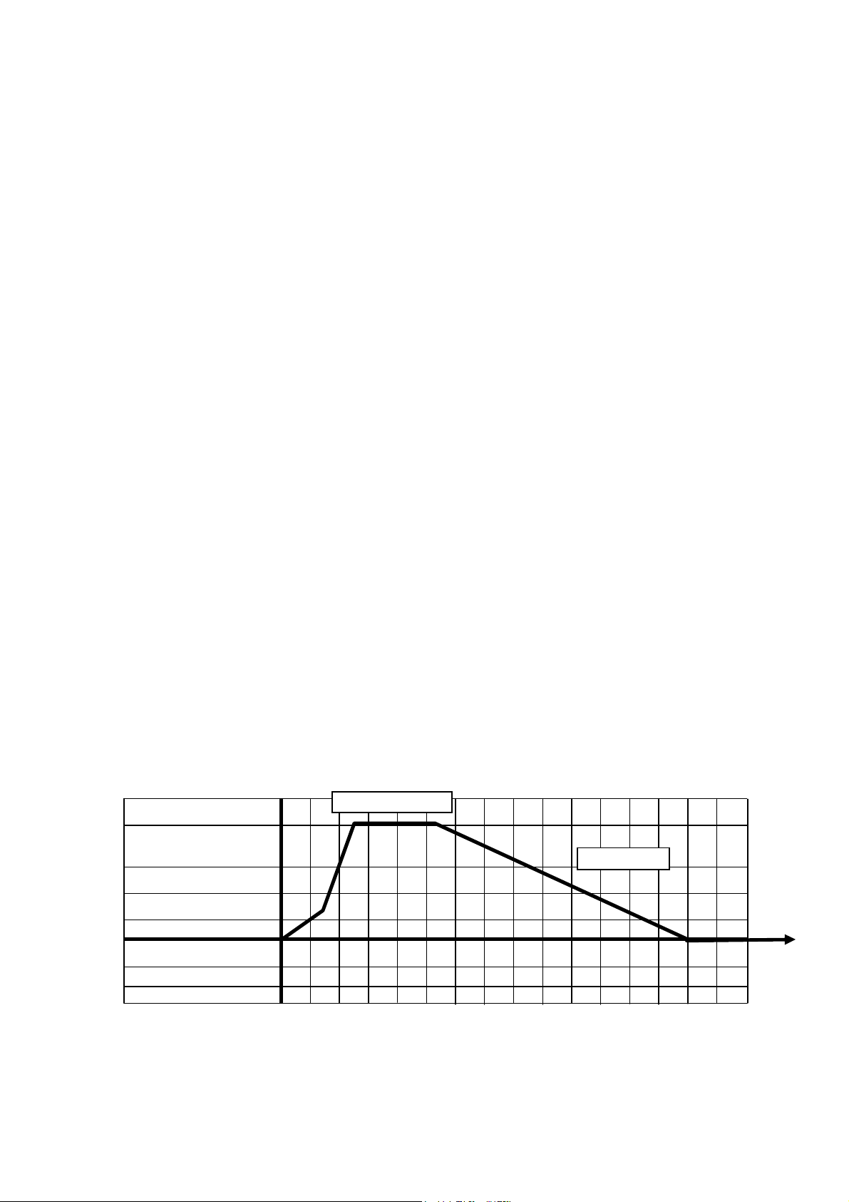
250°
F/ ~ 15.3
psig
Program 9, 10, 11, 12 for Liquids Slow exhaust 250ºF, With Purge (Process Sample)
These programs are intended for liquids in open or closed containers, but not sealed
containers, which their manufacturers declares their compliance with following
sterilization conditions:
♦ Sterilization temperature 250ºF
♦ Sterilization time 30 min
♦ Purge: 30 sec
♦ Slow exhaust
Performance Description:
The Saturated (controlled) steam is introduced into the chamber to the required
sterilization temperature.
Sterilization is controlled in a way that the sterilization temperature will not drop below
the required temperature; neither will it increase by more than 3.4ºF. The saturated
steam conditions are controlled in such a way that the fluctuation of pressure does not
allow a drop below 0.14 psi, nor an increase of 0.44 psi above the high limit of the Ste.
Temperature.
Slow exhaust is performed by slowly discharging the pressure from the chamber.
Pressure equilibration enables the opening of the door. Air is introduced into the
chamber through a microbiological filter until equilibrium is reached with atmospheric
pressure.
Note:
The temperature of the chamber must be below the end sterilization temperature
in the range of 140ºF - 212ºF, and the pressure must be below 2.0 psig to
enable the door to be opened.
Important:
Because of the difficulty to standardize the liquid cycle load, this cycle is not
intended for sterilization of materials that come into contact with patients, and
should be used for non-clinical applications only.
Program 9, 10, 11, 12 for Liquids Slow exhaust 250ºF, With Purge (Process Sample)
250°F 30 min
Ex Mode 4
8.5 psig
2.2 psig
0 psig
14.7 inHg
7.4 inHg
0 inHg
Page 55 of 105 pages
Page 60
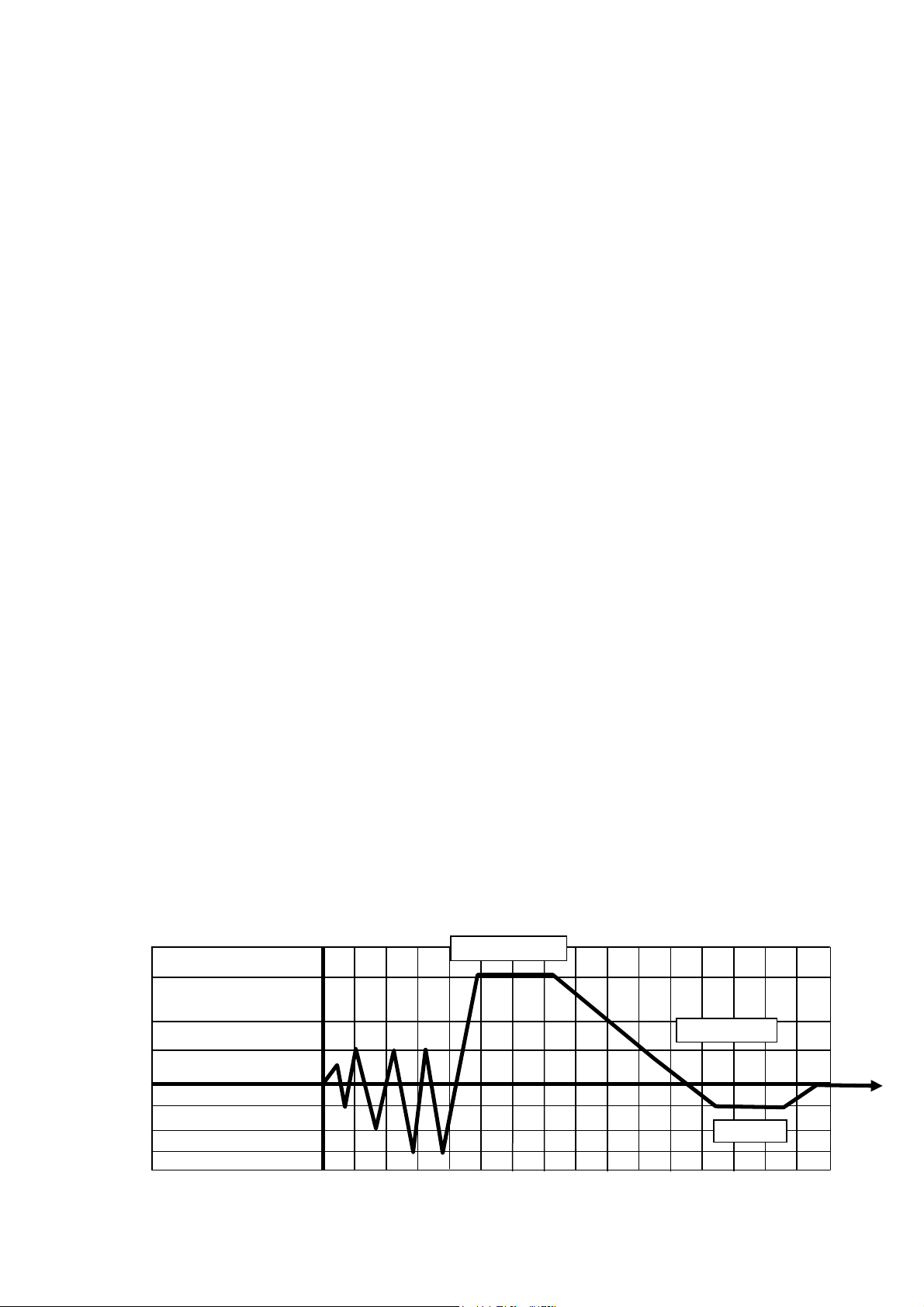
Program 13 - Bowie & Dick Test
This program is intended to test residual air in the chamber. The parameters are locked
in such a way that they cannot be changed. These are the parameters:
♦ Sterilization temperature 274ºF
♦ Sterilization time 3.5 minutes
♦ Drying time 2 minutes
The Bowie & Dick test pack should be placed horizontally on the bottom front of the
loading rack, near the door and over the drain.
Press 1 and then 3 within 2 seconds. This will select the cycle number "13" Bowie& Dick
test. Press the START key to run the test. This cycle is pre-programmed and cannot be
modified.
Performance Description:
Residual air is displaced by 4 vacuum pulses (down to 7.4 inHg) and 3 steam pulses up
to 8.5 psig. The 4th vacuum pulse is followed by the introduction of saturated (controlled)
steam into the chamber to the required Ste. Temperature.
Sterilization is controlled in a way that the sterilization temperature will not drop below
the required temperature neither it will increase by more than 5ºF. The saturated steam
conditions are controlled in such a way that the fluctuation of pressure does not allow a
drop below 0.14 psi or an increase of over 0.44 psi above the high limit of the Ste.
Temperature.
Fast exhaust is performed by rapidly discharging the pressure from the chamber. The
ejector is activated until the pressure drops to 7.4 inHg.
Drying is achieved by evacuating the vapor from the chamber in an "under-pressure"
phase for a period of 2 minutes.
Pressure equilibration enables the door to be opened. Air is introduced into the
chamber through a microbiological filter until equilibrium is reached with atmospheric
pressure.
Note:
The temperature of the chamber must be below 230 ºF and the pressure must
be below 2psig to enable the door to be opened.
Pass/Fail step
Remove the hot test pack from the autoclave carefully.
Remove the indicator sheet from the package and have it examined by a person trained
to interpret the Bowie & Dick Test.
If the test fails, repeat the test. If the test continues to fail, notify your authorized
Tuttnauer technical representative for service.
Program: 13- Bowie & Dick Test
274°F/ ~ 27.1 psig
13.3 psig
275°F 3.5 min
Ex Mode 1
0 psig
7.3 inHg
5.0 inHg
3.7 inHg
0 inHg
Page 56 of 105 pages
2 min
Page 61
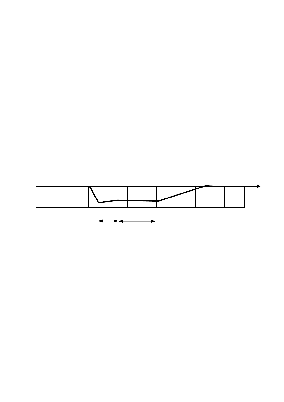
Program 14 Air Leakage Test
10 min
This program is intended to test air leakage in the chamber, through the door seal or any
other components.
This test is performed in the vacuum phase.
Press number 1 and then number 4 within two seconds, to select cycle 14 -Air Leakage
test.
Press START to automatically run the pre-programmed AAMI air leakage cycle
parameters.
At the end of the cycle, the unit printer will print "PASS" or "FAIL" on the tape printout.
In the event of test failure, repeat the test. In case of repeated test failure, notify your
authorized Tuttnauer technical representative.
Performance Description:
A vacuum is drawn in the chamber down to 6 inHg. At this stage all valves, and other
components are closed; and in the next 5 minutes the pressure is stabilized.
During the next 10 minutes the pressure is monitored.
The allowable change of pressure during these 10 minutes is 0.19 psig.
Program: 14- Air Leakage Test
0 psi
14.7 inHg
7.4 inHg
0 inHg
5 min
Page 57 of 105 pages
Page 62

7. PREPARATION BEFORE STERILIZATION
Note:
Liquids can only be sterilized in an autoclave with two temperature sensors in the
chamber.
Instruments to be sterilized must be clean, free from any residual matter, such as
debris, blood, pads or any other material. Such substances may cause damage to
the contents being sterilized and to the sterilizer.
1. Wash instruments immediately after use, to dispose of any residue.
2. Before placing an instrument into the sterilizer, make sure that the instruments
which are not of the same metal (stainless steel, carbon steel, etc.) are
separated.
Note:
Check manufacturers' instructions for sterilization of each item.
3. In case of carbon steel instruments are used with stainless steel trays, the tray
should be lined with a towel or paper wrap before placing the instrument.
There should be no direct contact between the carbon steel and the stainless
steel trays.
4. All instruments must be sterilized in an open position.
5. Place a sterilization indicator strip in each tray.
6. Once a week use a biological spore test indicator in any load to ensure
sterilization.
7. Make sure that all the instruments remain apart during the sterilization cycle.
8. Empty canisters should be placed upside-down in order to prevent
accumulation of water.
9. Do not overload sterilizer trays. Overloading will cause inadequate sterilization
and drying.
10. Allow a distance of approximately 1 inch (2.5 cm) between trays to permit
circulation of steam.
11. Wrapped instruments should be packed in material which promotes drying,
such as autoclave bag, autoclave paper and muslin towels.
Attention:
Verify that the packaging method is in accordance with good practice approach
and the packaging materials are in accordance with the applicable standards (e.g.
EN868 series).
Page 58 of 105 pages
Page 63
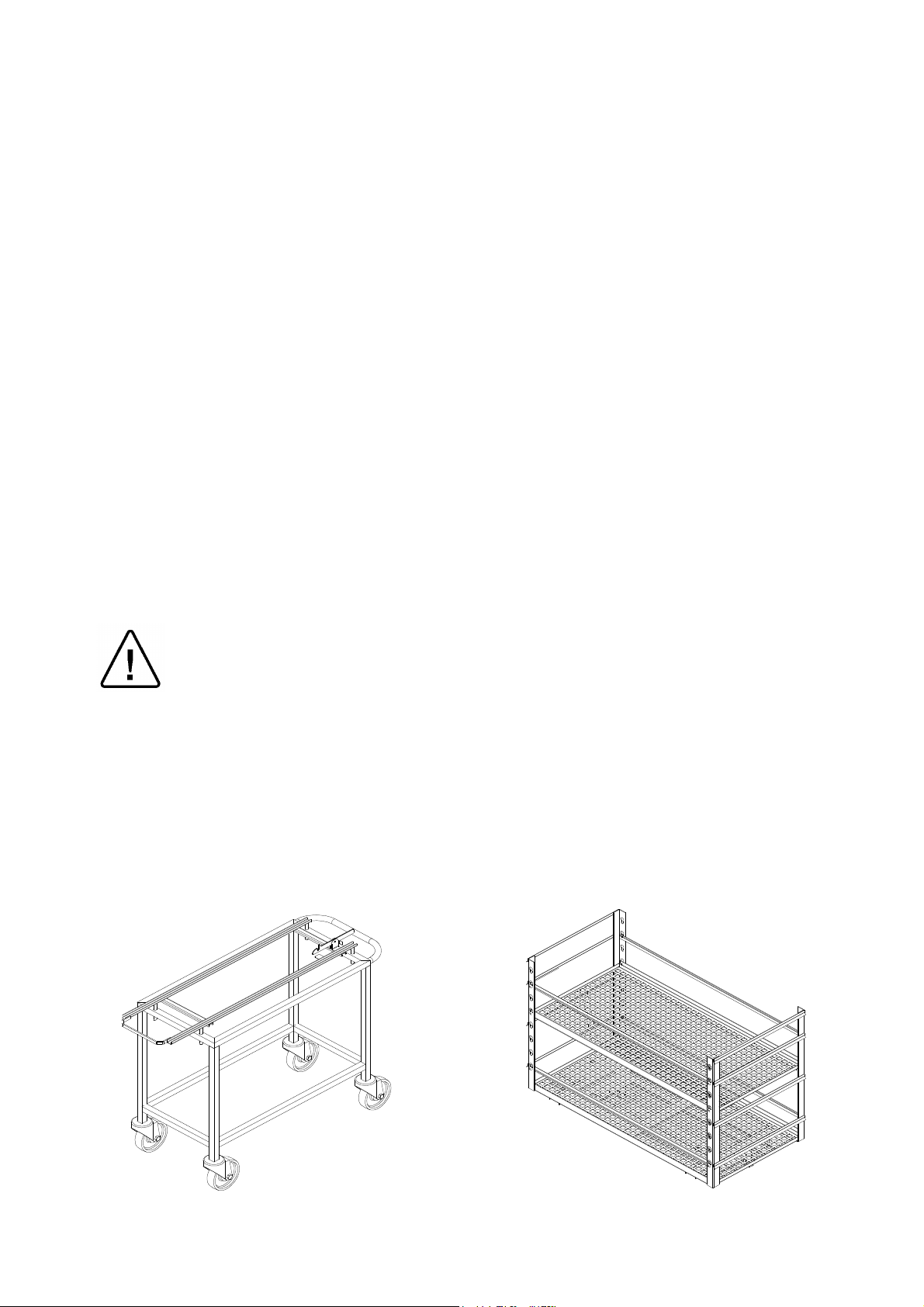
The following is recommended:
Transfer Carriage
Loading Cart
Tubing
Rinse tubing after cleaning with pyrogen free water. When placing in tray, ensure that
both ends are open, without sharp bends or twists.
Packs
Place packs upright on trays, side by side.
Packs should not touch the chamber walls.
Sterilization in slow discharge of the pressure
Use only heat-proof glass, filled 2/3 full.
Ensure that the glass container is covered but not sealed to prevent pressure build-up.
7.1 Loading
Every machine is supplied either with two (or more) stainless steel shelves, or with rails
for loading a loading cart from transfer carriage.
The transfer carriage is made of stainless steel and comes with adjustable legs to
balance the height of the loading cart to rails in the sterilizer chamber. The cart is
designed to slide smoothly off the carriage into the sterilization chamber.
The carriage moves on four heavy-duty castors, which are mounted on its base. The two
castors on the rear of the carriage are equipped with brakes. When the transfer carriage
is put in position for loading or un-loading the cart from the autoclave, the brakes must
be applied.
Caution!
It is strictly forbidden to load or unload the loading cart, if the transfer carriage
wheels brakes are not applied.
When loading the materials to be sterilized into the chamber, observe the rules
described in this chapter.
Do not overload the cart or the shelves as this can have adverse effects on the results of
the sterilization and drying. Leave space between the packs or wrapped instruments to
allow complete removal of air pockets in the air removal stage, and for free penetration
of steam in the heating and sterilization stages.
Page 59 of 105 pages
Page 64

7.2 Un-loading
1. When the buzzer signals the successful completion of a cycle, open the door
and let the load cool down for several minutes.
2. Maneuver the Transfer Carriage into position to line up the rails with the rails of
the autoclave, lock the two locking wheels.
3. Remove the loading cart (or the containers) onto the Transfer Carriage and
place aside to cool down.
4. Allow the load to cool down in an area with minimum passing traffic (to avoid
the possibility of touching the hot load), and without air movement (air
conditioning, etc.). Do not touch the hot load. Hot loads absorb moisture and
may absorb bacteria from the hand.
5. Do not transfer a hot load to metal shelves for cooling. Perform a visual
inspection to ascertain that sterilizing indicators have made the required color
change, and that the load is dry.
The load is to be rejected if:
a. The package has been compressed.
b. The package is torn.
c. The load is wet (water droplets signs).
d. The load fell on the floor.
e. Condense can be observed on the lid.
f. The PCD or other indicator present – Faulty cycle.
Warnings!
During loading and unloading use safety gloves and glasses in accordance with
local safety regulations and good practice.
It is strictly forbidden to enter the autoclave chamber!
If, for any reason (for cleaning, maintenance or if something falls down), it is
necessary to enter the chamber, the person must lock the system by pressing the
emergency switch and take the key with him to prevent accidents and
unauthorized use.
Page 60 of 105 pages
Page 65

8. OPERATING INSTRUCTIONS
Attention!
Liquids can only be sterilized if there are two PT 100 flexible temperature sensors
in the chamber.
Warning!
Do not operate the autoclave in the presence of dangerous gases and vapors.
Observed the manufacturer recommendations sterilization data for each type of
material.
Starting the autoclave
1. Check that the feed water manual valve is open.
2. Check that the compressed air manual valve is open, and the pressure is set
at 115 psi.
3. Check that the steam inlet manual valve is open.
4. Power the autoclave by turning ON the main power switch.
5. Check that the jacket pressure gauge, reaches 2.4 bars (35 psi).
Note:
Before the first operation of the day, warm up the jacket for at least 20 minutes
with the door closed, even if the READY LED is lit up, and carry out a BOWIE &
DICK test.
Running a Sterilization Program
1. Open the door by turning the door wheel handle, counter clockwise to release
the locking arms.
2. Load the sterilizer.
3. For liquid loads, choose the two containers that contain the most liquid, and
insert the two temperature sensor into both.
4. Close the door by pushing it towards the chamber frame and turning the wheel
handle clockwise until the word READY appears in the first row, indicating
autoclave is ready to start operation.
5. Select the sterilization program according to the type of material to be sterilized
by pressing the relevant keys as described in Chapter 3.
6. Press the START key, to operate the cycle. The entire sterilization process
automatically proceeds. The signal light RUN on the control panel is lit.
7. At the end of the cycle a buzzer sounds, and the word "END" is displayed.
Press the STOP key to cancel the buzzer. Open the door as indicted in step 6
and take out the sterilized material from the chamber ensuring the environment
is sterile.
Note:
Verify that the pressure in the chamber is atmospheric pressure. Do not attempt
to open the door if the pressure in the chamber is above atmospheric pressure.
When a sterilization program is running, the LED RUN lights up on the control
panel.
Caution!
The sterility of un-wrapped instruments cannot be maintained if exposed to a
non-sterile environment.
Page 61 of 105 pages
Page 66

Warning!
Loading or unloading of material from the chamber can only be done when the
door is completely open. It is forbidden to put a hand or any other part of the body
inside the chamber while closing the door.
8.1 Failed Cycle
Note:
In case of a failed cycle or of a manual stop by the operator, the two LEDs RUN
and FAIL are lit. The reason for failure is displayed on the screen. At the end of the
cycle an interrupted sound is heard. Press STOP to cancel the alarm.
In the case of a failed cycle do the following:
1. Press STOP.
2. Solve the problem.
3. Log the displayed message in the autoclave log book or any other appropriate
document.
4. If you cannot solve the problem, turn OFF the autoclave and call for Service.
Note:
Verify that the pressure in the chamber is atmospheric pressure. Do not attempt
to open the door if the pressure in the chamber is above atmospheric pressure.
8.2 Aborting a Cycle
1. Press the STOP key; the autoclave automatically goes through a shut down
sequence. The unit will either open the drain valve to remove pressure from
the chamber or open the vacuum break valve, depending upon the phase of
the cycle.
2. The autoclave will signal the operator that the cycle has been aborted and will
advise the operator when the door can be opened. (see above)
Note:
When a power failure occurs, the autoclave holds the cycle at that point when the
power was lost. The system stays in the locked down safe mode until the power is
restored. At the power restoration the controller follows the abort sequence
described above.
Warning!
DO NOT ATTEMPT TO OPEN THE DOOR UNTIL NOTIFIED THAT THE ABORT
SEQUENCE IS COMPLETE. IF THE CONTROLLER DOES NOT INDICATE THAT
THE SEQUENCE IS COMPLETE, DO NOT ATTEMPT TO OPEN THE DOOR.
CONTACT YOUR TUTTNAUER TRAINED AND CERTIFIED AUTOCLAVE
TECHNICIAN.
Page 62 of 105 pages
Page 67
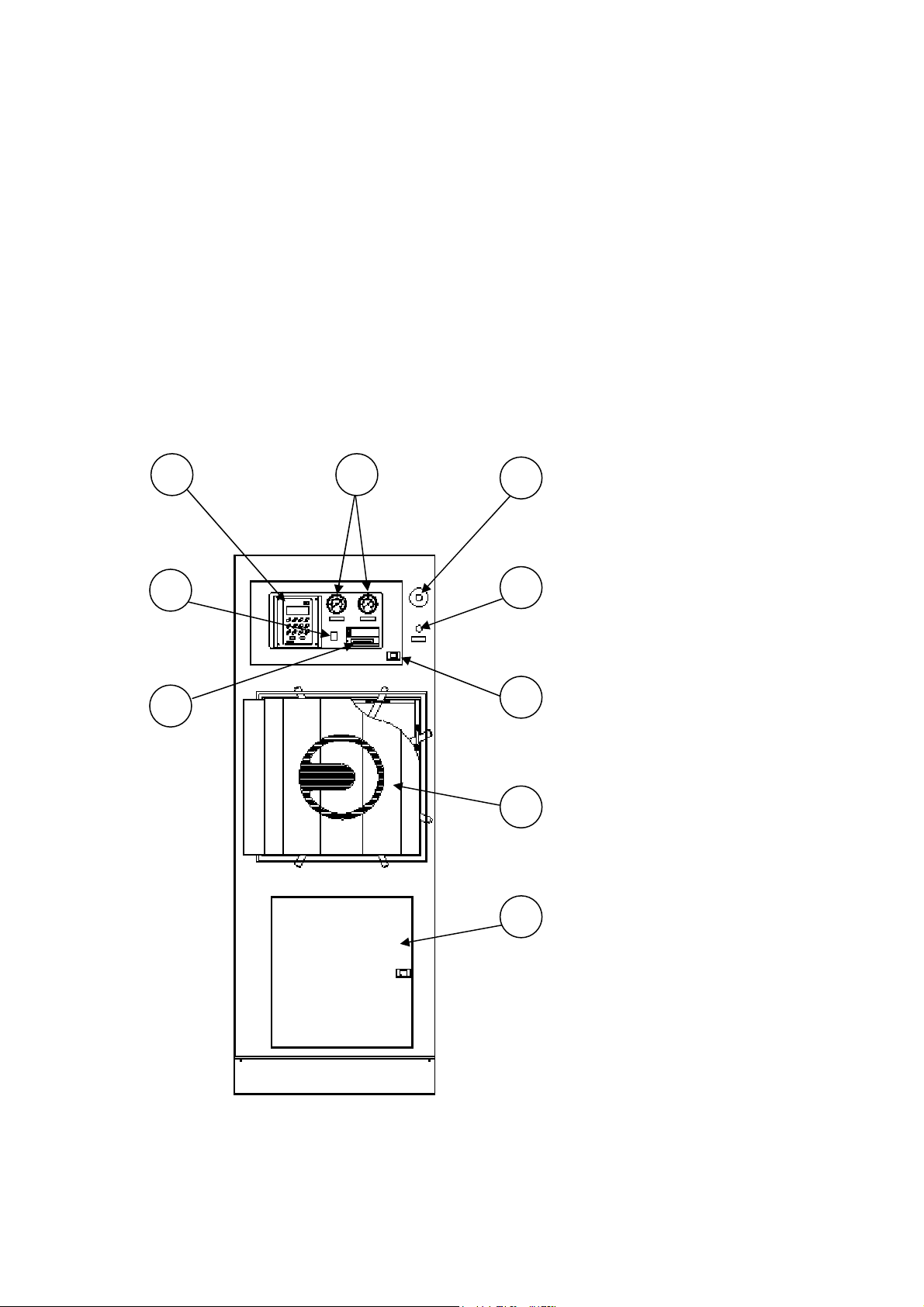
8.3 Repeating a Cycle
Legend:
6
5
7
2
3 4
1
8
9
The Protection Glass Door is a safety and maintenance feature to protect the control
panel, manometers and switches, from steam during opening of the chamber-door at the
end of a program.
Since it is inconvenient to reach beyond the glass panel whilst the autoclave is in
operation, an additional switch has been mounted on the front outer panel, to allow for
external operation control.
If the operator does not require to select a different cycle, he just presses the START
switch after the loading has been completed, and does not need to open nor close the
Protection Glass Door every time the autoclave is operated.
The Emergency STOP switch terminates the operation of the autoclave at any time.
1. Printer
2. Operating Switch
3. Operation Panel
4. Chamber and Jacket
pressure gauges
5. Emergency STOP switch
6. START Switch
7. Protection Door Latch
8. Chamber Door
9. Service Access Door
Page 63 of 105 pages
Page 68

This page intentionally left blank.
Page 64 of 105 pages
Page 69

SERVICE INSTRUCTIONS
Warning!
These service instructions are for the use of qualified personnel only! To avoid
electric shocks, do not perform any servicing other than that specified in the
operating instructions unless you are qualified to do so. Refer all servicing to
qualified service personnel.
When servicing the autoclave, disconnect the all electrical power supplies to the
unit. This is done by switching OFF the main power supply switch, or by unplugging the electrical power main supply cords.
Page 65 of 105 pages
Page 70
liquids, clean the chamber at the end of
9. MAINTENANCE OF AUTOCLAVE
9.1 Preventive and Periodical Maintenance
1. Clean the strainer at the bottom of the chamber.
Before each
cycle
User
Daily
2. Verify that the door gasket and the surface that the
gasket is pressed on are clean.
3. Keep the door closed between sterilizing cycles.
1. Clean the door gasket every day with a soft cloth.
2. Before the first operation of the day, warm up the
jacket for at least 20 minutes with the door closed,
even if the READY LED is lit up.
3. Keep the door closed between sterilizing cycles.
4. Carry out a BOWIE & DICK test at the beginning of
each day after warm up.
5. Drain the compressor tank before starting operation
(if applicable).
6. If sterilizing
every day.
7. At the end of the day leave the door open.
1. Clean the cabinet and door parts, the internal walls of
the autoclave, the shelves and the shelf rails with a
soft cloth and household detergent. Clean the
chamber while the autoclave is cold. The
detergent shall be flushed away with water.
If you used tap water, for the final flush use distilled
or mineral-free water.
Caution!
Do not use steel wool or steel brush as this can
damage the chamber!
2. Place several drops of oil on all the door spindles and
Weekly
User
pins (if applicable).
3. Drain the generator (if applicable) as follows:
a. Switch OFF the power.
b. Wait until the pressure decreases to 0.5 bar
(watch the pressure gauge).
c. Open the drainage manual valve for a few
seconds till the glass tube becomes empty, and
then close the valve.
d. Drain the water level tube by opening the tube’s
valve located at the bottom elbow
connecting the tube to the vessel.
4. At the end of the week, or if the autoclave will stand
for a prolonged period, clean the chamber when it is
cold, and leave the door open.
Page 66 of 105 pages
Page 71

On Autoclaves with Automatic Doors
1. Once a month before the weekend, follow these
steps:
a. Remove the door gasket, and thoroughly clean
the door gasket groove.
b. Remove any stains or corrosion from the door
Monthly
gasket groove, and blow out all traces of dirt with
compressed air.
Technician/User
c. Thoroughly clean the door gasket.
d. Leave the door gasket out for the weekend.
e. Before start of day/shift after the weekend, re-
place the door gasket according to the instructions in
the “Replacing the Door Gasket“ section.
1. Clean water strainers on pipelines while autoclave
does not operate (idle).
2. Verify sewage pipe is not clogged ensuring free
drainage of sewage liquids. It is important that
sewage liquids do not overflow at the working site.
3. Disassemble the steam –traps and clean them. The
cleaning operation requires cleaning of the strainer
Quarterly
inside the steam-trap. This can be done by rinsing
and removing any dirt, which causes blockage.
Technician
4. Check the piping connections and tighten where
necessary to avoid leakage.
5. De-scale the generator (if applicable).
6. Verify that the water quality complies with the
requirements as detailed in the Water Quality
paragraph.
Page 67 of 105 pages
Page 72

clean the door
On Autoclaves with Manual Doors
1. Every six months before the weekend, follow these
steps:
a. Remove the door gasket, and thoroughly
gasket and the groove.
6 months
b. Leave the door gasket out for the weekend.
c. Before start of day/shift after the weekend, re-
place the door gasket according to the instructions in
the “Replacing the Door Gasket“ section.
All autoclaves
1. Replace the 0.01µ air filter
1. Perform an overall check of the locking system and
replace worn parts.
2. Check and tighten where necessary the electrical
connections in the electrical board, connection box,
motors, electrical valves, locking device screws and
instrumentation.
3. Clean the electronic control unit, using a vacuum
cleaner.
4. Check the door gasket and replace if damaged.
5. Ensure periodical tests are done on time.
6. Check the steam-traps and replace if worn.
7. Calibrate the control system
8 Validate the applicable cycles
9. Check and verify tight closing of all tightening bolts of
the side guides, as well as top and bottom guides (if
Technician
applicable). Replace worn bolts if necessary (on
horizontal or vertical door).
10. Check and verify tight closing of all tightening bolts of
Yearly
the bronze strips. Replace worn bolts if necessary (on
horizontal or vertical door).
11. Check and verify tight closing of all tightening bolts of
the door guide rail (including the door's wheel). Replace
worn bolts if necessary (on horizontal or vertical door).
12. Check the hydraulic piston including oil level. Check the
hydraulic system for leakage, worn or loose component
(on horizontal or vertical door).
13. Disassemble the door cover, check and tighten all
locking mechanism bolts (on manual or automatic
hinged doors).
14. Check operation of the micros-witches. Verify that they
are placed tightly as required.
15. Check the safety valve. Allow the safety valve to blow
off by letting the pressure increase until it reaches the
working pressure + 10%. This verifies that the safety
valve operates as required and the valve’s seat is kept
free of mineral deposits.
Note:
Yearly maintenance should always be accomplished
by a trained sterilizer service technician.
Page 68 of 105 pages
Page 73

Notes:
1. Keeping the inside of the autoclave clean will lengthen its life and its proper
operation.
2. Ensure the chamber is empty and cold during all cleaning.
3. For all cleaning use ordinary household stainless cleaner, and rinse first with
tap water, and then with distilled or mineral free water.
4. Use only mineral-free water for the steam generator as detailed in the Water
Quality paragraph, (If applicable).
5. Keep the door closed between sterilizing cycles.
6. If you see or hear anything extraordinary, stop using the autoclave and call for
service.
Periodical Tests
1. Once a year calibrate and validate the autoclave.
2. Periodical safety tests (pressure vessel and electricity) shall be
performed by an Authorized Inspector at intervals as required by the
local laws, rules or regulations.
Periodical safety tests should be performed by an authorized inspector at
intervals as required by local law, rules or regulations.
Notes:
Ensure periodical tests are done on time!
Page 69 of 105 pages
Page 74

9.2 Safety Tests after Repair
Attention!
After every repair or dismantling the enclosure, the autoclave should pass two
electrical safety test by the qualified Service Engineer. The following shall be
performed:
1. Enclosure Leakage Current Test.
Every autoclave should pass this test as follows:
1. Connect the electrical cord to the autoclave.
2. Turn on the main switch on the right side of the autoclave.
3. Short-circuit the L and N pins on the cord's plug.
4. Connect the Short-circuit pins to the L pole on the Megaohm Tester.
5. Connect the earth pins to the earth pole on the Megaohm Tester.
6. Impose an electrical potential of 500-1000V on the tested autoclave.
The insulation resistance should be at least 2 MΩ.
The test is successful if there was no leakage.
2. Protective Earth Impedance Test
1. Connect the grounding pin of the power cord plug to one pole of an
Ohmmeter.
2. Connect any other metallic part (preferable – the metallic part of the
locking screw) to the second pole of the Ohmmeter.
3. The resistance should not exceed 0.3 Ω.
After performing these tests, the Service Engineer should complete and sign the
Work Order and the Log Book.
Page 70 of 105 pages
Page 75

9.3 Troubleshooting
Symptoms
1. Control unit not
energized. No displays
and lights on the front
panel.
2. Low pressure or no
steam pressure from
the external source.
3. Steam pressure
goes up beyond the
control point.
4. The conditioning
phase (pre-vacuum)
does not work.
Vacuum not produced
in the chamber or
vacuum level
insufficient.
Steam does not flow
through the steam inlet
or low steam pressure.
5. Pre-vacuum phase
completed but
temperature and
pressure is low and the
sterilization point is not
reached or takes a
long time to do so.
Possible causes check-ups and tests Corrections
1.1 The control circuit breaker switched
off or defective.
1.2 The power switch on the front panel of
the autoclave is defective.
2.1 Low pressure on the steam supply
line.
2.2 Pressure reducer faulty or set too
low.
3.1 The electronic pressure transducers
or measuring circuits faulty or out of
calibration.
3.2 Leakage through the steam to jacket
valve.
4.1 The vacuum valve passing water
through the ejector stuck or damaged.
1.1 Switch on the circuit
breaker or replace it.
1.2 Replace the defective
switch.
2.1 Fix pressure on the steam
supply line.
2.2 Set or replace the
pressure reducer.
3.1 Check and calibrate
pressure-measuring circuits
or replace transducers.
3.2 Check, fix or replace the
steam to jacket valve.
4.1 Check, repair or replace
the vacuum valve.
4.2 The exhaust to ejector valve stuck or
damaged.
4.2 Check, repair or replace
the exhaust to ejector valve.
4.3 Door not properly closed, gasket
damaged or incorrectly set.
4.4 Leakage at the vacuum or exhaust
piping.
4.3 Close the door, fix or
replace the gasket.
4.4 Check and tighten fitting
joints, replace the defective
piping.
4.5 Control system trouble. 4.5 Replace the control
boards.
4.6 Steam inlet valve blocked or
damaged.
4.7 Low pressure at the steam supply
line.
5.1 Steam inlet valve blocked or
damaged.
5.2 Low pressure at the steam supply
line.
5.3 Control system trouble.
4.6 Fix or replace the steam
valve.
4.7 Check the steam supply
pressure as shown in par. 2.
5.1 Fix or replace the steam
valve.
5.2 Check the steam supply
pressure as shown in par. 2.
5.3 Replace the control
system.
6. Temperature rises
above the preset
sterilization value.
7. Fast or slow exhaust
phases do not
function; chamber
pressure remains high
or exhaust takes too
long.
6.1 Steam valve leaks.
6.2 Steam line pressure too high or
pressure reducer set too high.
6.3 Control system trouble.
7.1 The fast or slow exhaust valves
stuck or damaged.
7.2 Steam valve leaks.
7.3 Control system trouble.
Page 71 of 105 pages
6.1 Repair or replace the
steam valve.
6.2 Adjust steam pressure
correctly.
6.3 Replace control boards.
7.1 Repair or replace the
damaged valve.
7.2 Repair or replace the
steam valve.
7.3 Replace the control
boards.
Page 76

Symptoms
Possible causes check-ups and tests
Corrections
8. Drying stage does
not work.
9. The air inlet does
not work.
10. Unsatisfactory
results of sterilization
process.
11. Drying incomplete
packs remain wet.
12. The door does not
close.
13. The door does not
seal.
14. The door does not
open.
8.1 Trouble with the vacuum system.
8.2 Steam valve leaks.
8.3 Control system trouble.
9.1 Air inlet valve clogged or damaged.
9.2 Air filter jammed.
10.1 Incomplete removal of air pockets.
10.2 Sterilization conditions improper
temperature or pressure too low, ster.
time too short.
10.3 Incorrect loading of autoclave, air
trapped in the load.
11.1 Insufficient steam pressure to
jacket.
11.2 Insufficient vacuum.
11.3 Steam trap does not eliminate the
condensate.
11.4 Incorrect loading of the autoclave.
12.1 Low pressure at the air supply line.
12.2 CLOSE DOOR solenoid valve
transmitting air pressure to the door
actuator is stuck or damaged.
12.3 Door drive actuator damaged.
12.4 OPEN DOOR button is defective.
12.5 Control system trouble.
13.1 Low pressure at the air supply.
13.2 Low steam pressure at the door
gasket.
13.3 The pressure to gasket pneumatic
valve blocked or damaged.
13.4 The solenoid or pneumatic valves,
which control the pressure or vacuum to
gasket stuck or damaged.
13.5 Control system trouble.
14.1 Low pressure at the air supply line.
14.2 Insufficient vacuum to gasket, due
to trouble with the vacuum system.
14.3 Gasket improperly seated or
damaged.
14.4 OPEN DOOR solenoid valve
transmitting air pressure to the door
actuator is stuck or damaged.
14.5 Door drive actuator damaged.
8.1 See par 4.
8.2 Repair or replace the
steam valve.
8.3 Replace the control
boards.
9.1 Repair or replace air inlet
valve.
9.2 Replace the air filter.
10.1 See trouble related to
vacuum system par 4.
10.2 Set the temp. and time
correctly according to the sort
and quantity of material.
10.3 See par. Preparation
before Sterilization.
11.1 Set or fix the pressure
transducer.
11.2 See problems related to
vacuum par 4.
11.3 Clean or repair the
steam trap.
11.4 Reload the autoclave
correctly.
12.1 Set the air pressure;
22psi.
12.2 Fix or replace solenoid
valve.
12.3 Fix or replace actuator.
12.4 Replace the button.
12.5 Replace the control
boards.
13.1 Set the air pressure;
22psi.
13.2 Set the steam pressure;
1.5 - bar.
13.3 Fix or replace the
pneumatic valve.
13.4 Repair or replace the
defective valve.
13.5 Replace the control boards.
14.1 Set the correct air
pressure (which has to be
atmospheric pressure).
14.2 See paragraph 2.
14.3 Mount the gasket
suitably or replace it.
14.4 Repair or replace the
faulty valve.
14.5 Fix or replace actuator.
Page 72 of 105 pages
Page 77

Symptoms Possible causes check-ups and tests
15. Problems related
to the control system.
The keypad or display
out of order.
No response when
pressing any key on
the keyboard.
Disordered response
to manual controls.
Pressing one key gives
the effect of pressing a
different key. Cycle
does not start when
pressing the START
key.
Pressing the STOP
key, system does not
react. Switching the
instrument on,
initialisation is not
correct. Printer does
not work or printing is
incoherent.
15.1 Check if the flat cable or MOLEX
connectors between the control boards
and keyboard are well plugged in.
15.2 Power supply out of order.
15.3 Control boards or keyboard faulty.
15.4 Paper to printer missing or quality
unsuitable.
15.5 Flat cable connection between
control board and printer is not plugged
in correctly.
There are interruptions or loose
contacts.
15.6 Printer damaged.
Corrections
15.1 Plug in firmly the
MOLEX connectors.
15.2 Fix the power supply.
15.3 Replace the defective
board of the
microcomputer unit.
15.4 Insert a paper roll
inside the printer. Make
sure you use the correct
type of paper.
15.5 Plug in the connection
or replace it.
15.6 Fix connection or
replace the printer.
16. Cycle FAIL due to
Temperature High or
Low
Pressure High or Low
16.1 Temperature sensor disconnected
or loose connection. Sensor damaged.
16.2 Pressure transducer, faulty.
Mechanical or electrical connections or
transducer damaged.
16.1 Fix connection or
replace the sensor.
16.2 Fix connection or
replace the transducer.
Page 73 of 105 pages
Page 78
9.4 Test Points – Cat 2007
NUT TP FUNCTION
TP1 GND
TP2 Analog Input N 13 (Door 1 Press.)
TP3 Analog Input N1 (Cond. Temp.)
TP4 Analog Input N14 (Door2 Press.)
TP5 Analog Input N 2 (Cond. Temp.2)
TP6 Analog Input N 15
TP7 Analog Input N 3 (Temp.)
TP8 Analog Input N 16
TP9 Analog Input N 4 (h-electrode)
TP11 Analog Input N 5 (l-electrode)
TP13 Analog Input N 6 (Pressure)
TP15 Analog Input N 7 (Jacket press.)
TP17 Analog Input N 8 (Gen. Press.)
TP19 Analog Input N 9 (Temp.2)
TP21 Analog Input N 10 (T5)
TP23 Analog Input N 11 (T6)
TP25 Analog Input N 12 (Chamber Electrode)
Page 74 of 105 pages
Page 79
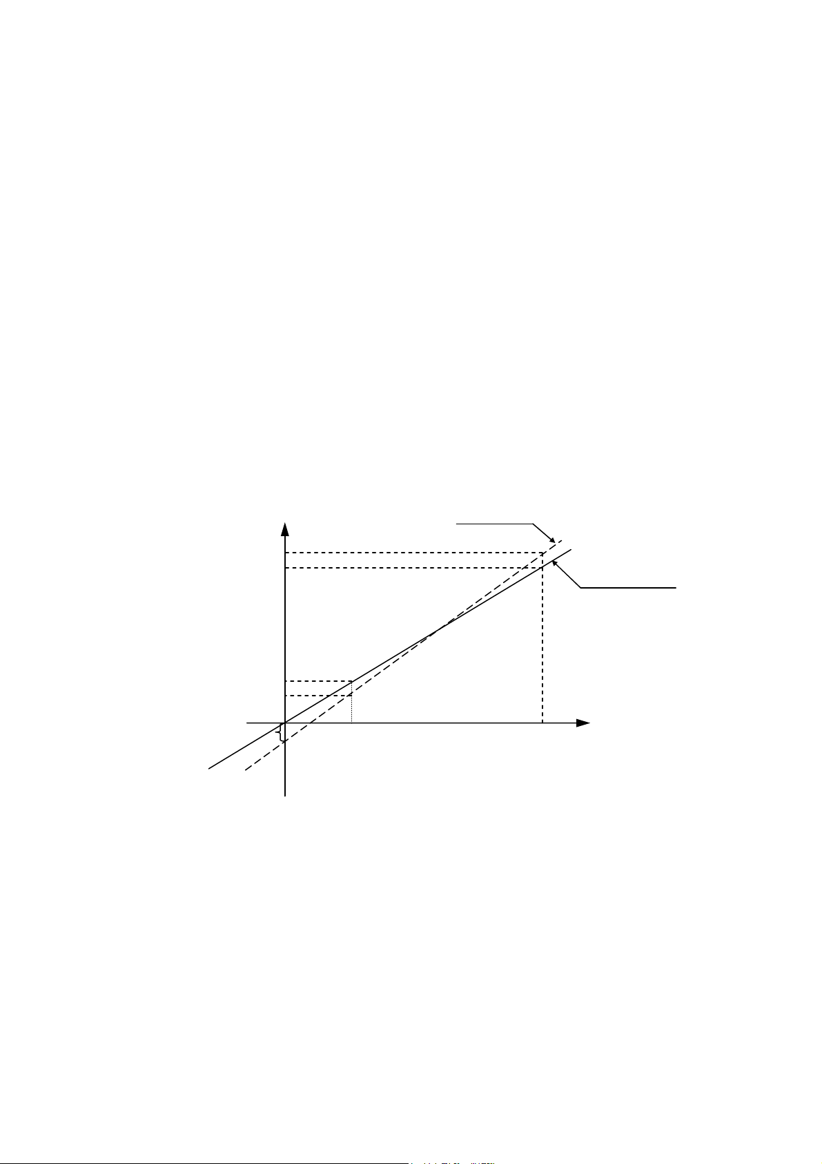
9.5 Calibration
a
INPUT FROM SENSOR
The programming of the calibration procedure is almost identical for both temperature
and pressure. Calibration is performed digitally.
The temperature and pressure measuring circuits are designed with components having
a 1% precision. The temperature circuit is linear and has an output of 100mV-2400mV
for a temperature range of 68ºF-302ºF (20ºC-150ºC).
The pressure circuit is also linear and has an output of 100mV-2400mV for a pressure
range of 0 -58 psi. (0-400 kPa).
The measuring at the A/D is void for values higher than 2400mV or lower than 100mV.
Even though the precision of the components of the circuit is 1%, the acceptable
deviation can reach ± 5%, therefore calibration is necessary.
The system has a non-erasable memory in which the OFFSET and GAIN data of the
sensors are stored. This data may be inserted into the system, through either
programming or directly through the autoclave.
READ
Y
310
ACTUAL
PRESURE
100
X
V
1
V
2
The calibration method enables the insertion of this data into the system in order to
perform the automatic correction of the OFFSET and GAIN.
Before calibrating it is recommended to find two points that have to be inserted into the
system (temperature or pressure).
Page 75 of 105 pages
Page 80
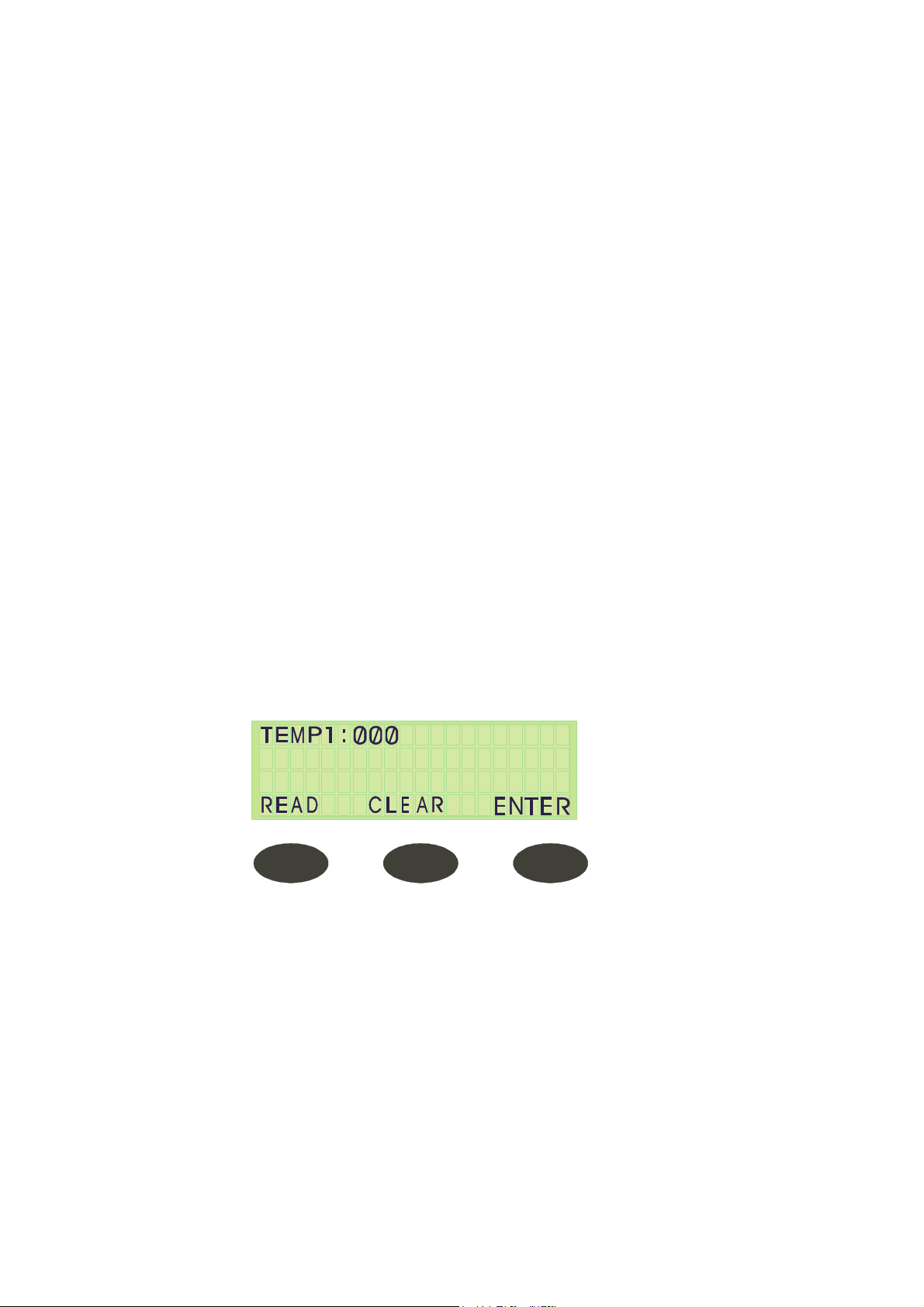
9.5.1 Calibrating Temperature and Pressure
Return to the ST.BY screen and select the OPTION command key.
The word CALIB is displayed above the middle command key. Press the middle key and
the same screen for entering the SETUP code will appear.
Enter the correct code via the digital key; the system begins displaying the calibration
options.
Note:
1. If the code is not entered within 15 seconds, the display returns to the
ST. BY screen.
2. If the code is incorrect it will return to the ST.BY screen
3. In all screens following the code entry screen, the middle command key
is CLEAR and the right key is ENTER. Pressing on either of these keys
opens up the next screen.
4. The values in all the following screens can only be changed via the
UP/DN keys. When the correct value is displayed, press ENTER and
the system will progress to the next screen.
Once the entry code has been entered, the following screens appear:
Temp 1:
Temperature of sensor 1
This screen requires a code. Press the UP key once to enter the code value ØØ1 and
press ENTER.
A screen displaying 4 Temp values appears:
A 140 (100) R 140 (100)
A 226 (130) R 226 (130)
Press the right button (F3) to scroll through the different values, which may be changed
using the UP/DN keys only.
After F3 is pressed, when it is on the last value, the next screen will appear.
Press the middle button (F2) to read the value of the sensor.
Press STOP to discontinue a cycle.
Page 76 of 105 pages
Page 81

Temp 2:
Temperature of sensor 2.
Refer to Temp1 for instructions.
Temp 3 (Option):
Temperature of sensor 1.
Refer to Temp1 for instructions.
Temp 4 (Option):
Temperature of sensor 2.
Refer to Temp1 for instructions.
Temp 5 (Drain)
Temperature of sensor 5
Refer to Temp1 for instructions.
Chm Pres (Chamber Pressure)
This screen requires a code to be entered.
Press the UP key once, to enter the value ØØ1 and press ENTER.
This provides the screen giving 4 pressure values:
A 14.5 (100) R 14.5 (100)
A 43.5 (300) R 43.5 (300)
Press the right button F3 to access different values that may be changed using the
UP/DN keys only.
After F3 is pressed when it is on the last value, it moves to the next screen.
Press the middle button F2 to read the value of the sensor.
Press STOP to discontinue a cycle.
Jkt Pres:
Jacket Pressure.
Refer to Chm Prs for instructions.
Gen Pres:
Generator Pressure.
Refer to Chm Prs for instructions.
D1 Pres:
Pressure in Gasket1.
Refer to Chm Prs for instructions.
D2 Pres: (Option) N/A
Pressure in Gasket 2.
Refer to Chm Prs for instructions.
After Enter is pressed, the calibration options are concluded and the display returns to
the ST.BY screen.
This calibration method enables the technician to change a certain point without
affecting a second point.
There are two working temperatures 273 ºF and 250 ºF (134ºC - 121ºC):
When checking chamber TC for 273 ºF (134ºC) it shows 270 ºF (132ºC)
When checking chamber TC for 250 ºF (121ºC) it shows 250 ºF (121ºC)
The temp for 273 ºF (134ºC) needs correction without changing the accurate Temp of
250 ºF (121ºC)
Page 77 of 105 pages
Page 82

The data should be set as follows:
Upper Row A 250 (121) R 250 (121)
A 270 (132) R 273 (134)
The system calibrates the new Offset and Gain and loads them into the non-erasable
memory.
As a result, while running a 273 ºF (134ºC), program the correction is automatically
made, while at 250 ºF (121ºC) there is no change.
9.5.2 An Example of Temperature Calibration:
Sensor no. 1 reads – 140°F (60ºC) and the actual temperature is 149°F (65ºC) (in the
lower range), and in the upper range reads 130ºC (266°F) and the actual temperature is
275°F (135ºC).
In order to calibrate and to change the values do the following:
1. Press OPTION (F2).
2. Press CALIBRATION (F2).
3. The system will ask an entering code, enter the code.
4. Temperature 1 is displayed. To change temp 1, enter the code and
press ENTER – (F3); several numbers will appear on screen. On the
left side of the uppermost row, a cursor appears which enables the user
to change temperatures.
5. Insert the actual temperature that was measured 149°F (65ºC) and
press ENTER (F3); the cursor will point to the Read temperature – R.
(upper right) Insert the read temperature, which was measured in the
autoclave 140°F (60ºC), and press ENTER. The cursor will point to the
actual –the lower left number.
6. Insert the actual temperature that was measured 275°F (135ºC) and
press ENTER (F3), the cursor will point to the Read temperature – R
(lower right). Insert the read temperature, which was measured in the
autoclave (130ºC), and press ENTER. Pressing ENTER will bring you
to the calibration of temperature 2. – If you want to calibrate
temperature 2 repeat all calibration steps, if not, press ENTER until the
main screen is displayed.
Page 78 of 105 pages
Page 83

9.6 Testing the Safety Valves
Attention!
Make sure that the test is performed while the door is closed.
Testing the Jacket Safety Valve
1 Mark the position of the pressure regulator adjustment knob.
2 Turn the adjustment knob one turn in the pressure increase direction.
3 On the solenoid valve battery, open manually valve 91. This is done by turning
the adjustment screw until the screw's slot is vertical.
4 Operate the autoclave and verify that the pressure increases.
5 Verify that the safety valve blows in the range of 40–44psi (2.8–3.0 Bar).
6 If the safety valve did not blow at the pre-set pressure stop the operation of the
autoclave, decrease the pressure to atmospheric pressure and replace the
safety valve with a new one.
7 If the safety valve was replaced, repeat step 1—5 to test the new one.
8 Close solenoid valve 91 (screw's slot is horizontal).
9 Readjust the pressure regulator to the original position. Use the marking as
mentioned above in step 1
Page 79 of 105 pages
Page 84
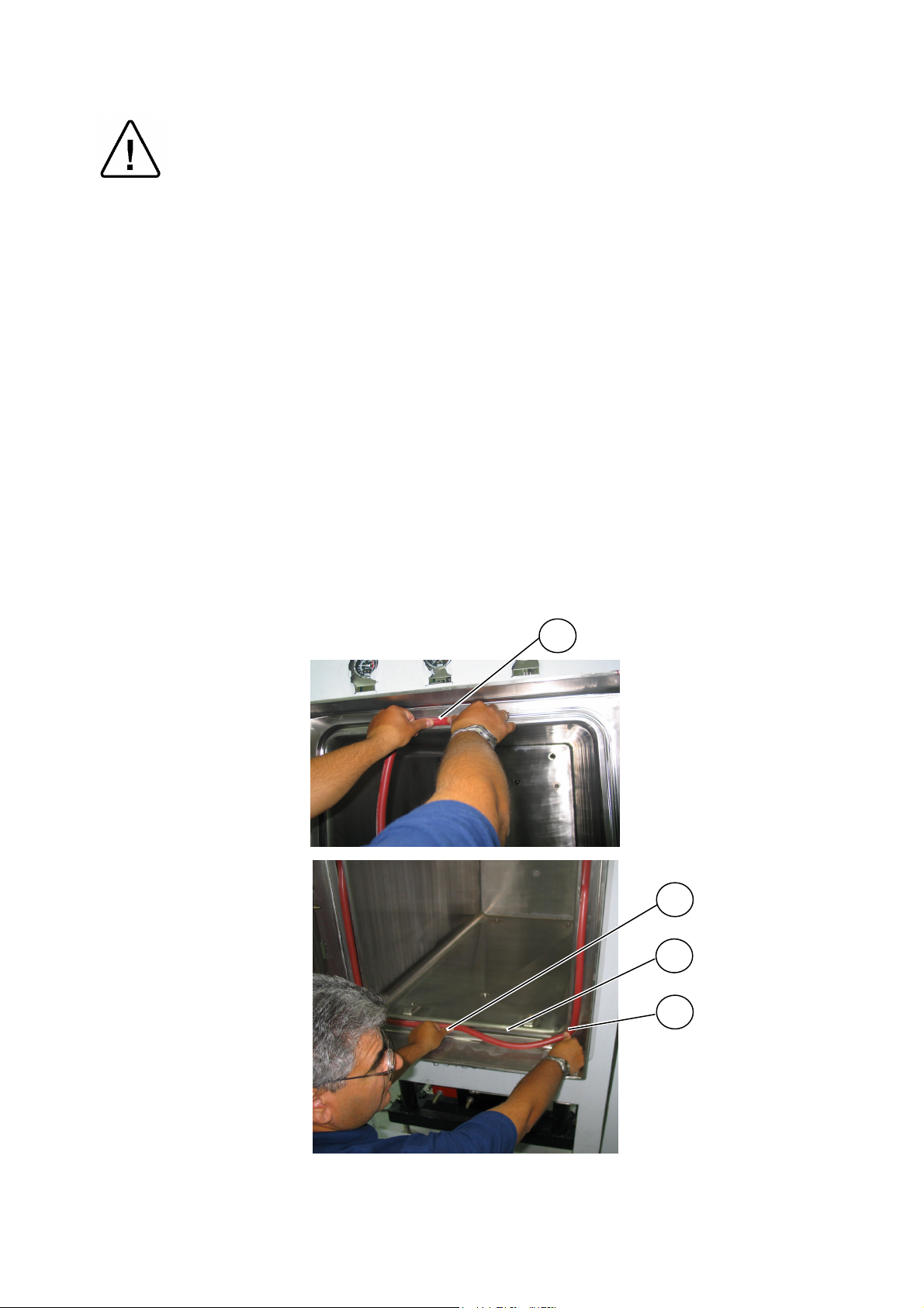
9.7 Replacing the Door Gasket
Warning!
Before replacing the gasket, verify that the autoclave is cold; that the power is
turned off; and, that there is no pressure in the jacket and in the chamber.
1. Remove the damaged gasket.
2. Check the new gasket and verify that it is not damaged.
3. Verify that the gasket groove is clean.
4. Begin inserting the gasket into the groove by pressing it into the middle of the
upper part of the groove. Verify that the point of the glued end (1) (the part of
the silicon tube where the two ends meet) is placed in the middle of the upper
groove.
5. Insert the gasket into the groove in the middle of each side (2) (top, bottom, left
and right) and in each corner.
6. Continue to insert the gasket into the groove in the middle of each loose part,
i.e. between two inserted points (3) & (4).
The final adjustment of the gasket will be done automatically at the first "closing door."
1
2
3
4
Page 80 of 105 pages
Page 85

10. SPARE PARTS LIST
Part No. Description
R ARM029-0006 Pressure Reducer, Steam, ½", Miyawaki
R ARM100-0069 Steam Trap, ½", without bypass,N125W, Nicholson
R ARM100-0070 Steam Trap, ½", with bypass, N125WSLR, Nicholson
R ARM172-0018 Check Valve, Swing, ½", NPT, St.St., CK-6
R ARM172-0020 Check Valve, Swing, ¾", NPT, St.St., CK-6
CMH440-0003 Strainer, chamber drain, 44/55
R CMT196-0004 Electrode, Water Level, Assembly, for TTA, Length: 58mm
CTP200-0040 Control Unit, Electronic, CAT2007, Horizontal, Complete
CTP201-0079 Panel, Keypad CAT 2007
CTP201-0090 Board, Electronic, HORIZ V6
CTP201-0091 Board, Electronic, HORAN V6
CTP201-0152 Power Supply, 5V, RS-25, Mean Well
CTP201-0160 Power Supply, 24V, RPD-65, Mean Well
CTP201-0230
Electronic Level Regulator, one electrode, 115V, DRL H S,
Gicar
ELC456-0003 Cable, Assy. Printer, Citizen 920, Horizontal
R ELE034-0017 Circuit Breaker, 1 pole, 4A, FAZ-C4, Moeller
R ELE035-0012 Switch, Rocker, 16A
R ELE035-0022 Single Polar Switch Hor.
ELE035-0095 Push-button actuator, Green, M22-D-G, Moeller
ELE035-0096 Contact Element, M22-K01, Moeller
ELE035-0135
Pushbutton, mushroom, KPMP2-10R+key, contact blocks with
holder KCBH-02, ABB
R ELE036-0019 Microswitch, MP320-5MAL, Microprecision Electronics
R FIL175-0039 Filter,Air, 0.01m, ½"
FIL175-0064 Strainer, ½" , St.St, Y Type, VS01, Victory valves
FIL175-0065 Strainer, ¾" , St.St, Y Type, VS01, Victory valves
R GAS550-0001 Gasket, Door, Silicon, 9mm, Model 55XX
R GAU029-0003 Gauge, Pressure, Steam, 0-60 psi, 2.5"
R GAU029-0012 Gauge, Pressure, Air, ¼"
R GAU029-0023 Gauge, Pressure, Steam, -30+60 psi
R PNE195-0039 Silencer ⅛", SFE 180, Sistem Pneumatica
PUM056-0002 Ejector, Water, ELL, ¾", Penberthy
Page 81 of 105 pages
Page 86
Part No. Description
R SVL029-0031
SOL024-0014 Subbase. Joinable, 35300048, Joucomatic ASCO
SOL024-0015
SOL024-0016
Connector, with integrated LED indicator, size 22, DIN 43650,
88122405, Asco
Solenoid valve, 1.2mm, w/o DIN connector, 18900002,
Joucomatic
SOL024-0017 Filter/regulator, 25µm, 1/8, 34225201, Joucomatic
SOL025-0051 Battery, 8 Solenoid Valves, NC, Complete, Series 189, ASCO
Valve, Safety, ½"-40 psi (ASME), Bronze base, 19M DC L40,
Conbraco
THE002-0009 Printer, CBN-920, parallel, CITIZEN
R THE002-0010 Paper, Roll, Printer CBN-920
R THE002-0020 Ribbon, Ink, Printer CBN-920
THE003-0003 Sensor, Temperature, Silicon, PT100, 6X100
THE003-0004 Sensor, Temperature, PT100x2, 6X100
THE003-0022 Sensor, Temperature, PT-100, 6x150, 1m Flexible st.st. Hose
R VLV171-0011
R VLV171-0012
THE003-0032 Controller, temperature, PT100/115 VAC, IC 912, Eliwell
THE005-0024 Switch, Pressure, RT112, Danfoss
THE006-0006 Transducer, Pressure, -1+3 Bar abs (Tecsis 3296)
VLV170-0001 Valve, Manual, ½", NPT, DN 15, DIN 3844
VLV170-0024 Valve, Needle, ¼", St.St
VLV170-0055 Valve, Manual, Ball, Mini, ¼", Sistem Pneumatica
VLV170-0140
VLV170-0142
Valve, water/steam, Air-Spring Operated, NC, Angle Seat, ¾",
St.St., 7010, Schubert
Valve, water/steam, Air-Spring Operated, NC, Angle Seat, ½",
St.St., 7010, Schubert
Gasket, Replacement Kit, Air-Spring Angle Seat Valve, ½",
7010, Schubert
Gasket, Replacement Kit, Air-Spring Angle Seat Valve, ¾",
7010, Schubert
Note:
R– Recommended spare parts list (to be maintained by the operator).
Page 82 of 105 pages
Page 87

SPARE PARTS FOR THE DOOR LOCKING MECHANISM
See Appendix 2 for exploded view of door locking mechanism.
Part No. Description
_ BEA031-0006 Washer, Tooth Lock, KM4, SKF
_ BEA031-0007 Washer, Locking, MB4, SKF
_ BEA031-0020 Bearing, Ball, 32004X, SKF
_ BOL191-0061 Bolt, Hex. Socket head, St.St., 1/4*25
_ BOL191-0101 Screw Set, Hex. Socket, St.St. 1/4*25
_ BOL191-0136 Screw, Flat Head, Socket Cap, 1/4NC*5/8"
_ BOL194-0347 Screw, Socket Head, Cap, Steel, 3/8NC*1½"
_ CMH070-1018 Locking Wheel, Door 44 XX, 55 XX
_ LOK550-0037 Pin, lower arm holder, 44 XX, 55 XX
_ LOK550-0001 Axis, Central, Locking Mechanism, 44XX, 55XX
_ LOK550-0002 Bushing, Central Axis, Locking Mechanism, 44XX, 55XX
_ LOK550-0003 Stopper, Ocolon, Locking Mechanism, 44XX, 55XX
_ LOK550-0004 Arm Holder, Upper, Door Locking Mechanism, 44XX, 55XX
_ LOK550-0005 Arm Holder, Lower, Door Locking Mechanism, 44XX, 55XX
_ LOK550-0008 Bushing, outer, Locking Mechanism, 44XX, 55XX
_ LOK550-0009 Base, Locking Wheel, Door Locking Mechanism, 44-55
_ LOK550-0013 Safety Rod, Door Locking Mechanism, 44-55
_ LOK550-0016 Locking Arm, Door Locking Mechanism, 55 XX
R PNE195-0042 Piston Assy. Manual Door, 1", 55 XX
Note:
R– Recommended spare parts list (to be maintained by the operator)
Page 83 of 105 pages
Page 88

11. VALVES NUMBERING
The valves in the drawing and the manual are numbered according to their function. The
following list includes all the valve numbers that are in use in Tuttnauer.
0.
1.
2.
3.
FEED WATER
MINERAL FREE
WATER
COMPRESSED
AIR
01. Change-over : steam / electricity
02. Locking door cylinder (front door)
03. Locking door cylinder (Rear door)
11. Feed water – cool jacket
12. Feed water – cool heat exchanger
13. Feed water – cool fast exhaust
14. Feed water – to reservoir
15. feed water – to vacuum pump/ ejector
16. Water outlet
17. Shut
18. Feed water – to air detector
21. Mineral free water - inlet
22. Detergent
23. To spray
24. Recycling inlet
25. Recycling outlet
31. Air inlet
32. Air inlet - to chamber
33. To splash cooling pipe
34-1. To door 1 seal
34-2. To door 2 seal
38-1. Open door 1
38-2. Open door 2
39-1. Close door 1
39-2. Close door 2
4.
41. Air release N.C.
42. Air release N.O.
AIR
43. Filtered air - inlet
44. Air Inlet
45. Air Leak Test
Page 84 of 105 pages
Page 89

5. VACUUM
6. DRAIN
7. EXHAUST
51. Vacuum - break
52. Vacuum - to pump
53-1. Vacuum - from door 1 seal
53-2. Vacuum - from door 2 seal
54. Vacuum Test N.C.
61. Drain – from reservoir
62. Drain – from jacket overflow
63. Drain – from vacuum pump / ejector
64. Drain – from chamber
65. Drain – from cooler
66. Drain – from sanitary filter
67. Drain – from steam generator
68. Drain – jacket
69. Drain – condense from seal
70. Exhaust – from chamber
71. Exhaust – to reservoir
72. Exhaust – to drain
73. Fast exhaust
74. Slow exhaust
75. Exhaust to ejector / to vacuum pump
76. Exhaust – from heat exchanger
77. Exhaust – from steam generator
78. Exhaust through heat exchanger
(pre-vacuum stage only)
79. Jacket steam trap
Note:
8. GAS
9. STEAM
S - SANITARY VALVE.
81. Inlet
82. Main inlet
83. Inlet through humidifier
90. Steam – from building source
91. Steam – to jacket (From outer source)
92. Steam – inlet
93. Steam – to chamber
94-1. Steam – to door 1 seal
94-2. Steam – to door 2 seal
95. Steam – to heat exchanger
96. Steam – to sanitary filter
97. Steam – from steam generator
98. Steam – to activate ejector
99. Steam – to air detector
Page 85 of 105 pages
Page 90

12. PRESSURE Vs TEMPERATURE FOR SATURATED STEAM
°C kPa °F psig psia °C kPa °F InHg psia
104.3 117.9 219.7 2.4 17.1 45.8 10 114.5 2.95 1.5
104.4 118.6 219.9 2.5 17.2 54.1 15 129.3 4.44 2.2
104.5 118.6 220.1 2.5 17.2 60.1 20 140.2 5.90 2.9
104.6 119.3 220.3 2.6 17.3 65.0 25 149.1 7.39 3.6
104.7 120.0 220.5 2.7 17.4 68.9 30 156.4 8.86 4.4
104.8 120.0 220.6 2.7 17.4 72.7 35 162.9 10.34 5.1
104.9 120.7 220.8 2.8 17.5 75.9 40 168.6 11.81 5.8
105.0 120.7 221.0 2.8 17.5 78.8 45 173.8 13.30 6.5
105.1 121.3 221.2 2.9 17.6 81.3 50 178.4 14.76 7.3
105.2 122.0 221.4 3.0 17.7
°C kPa °F Psig psia
105.3 122.0 221.5 3.0 17.7
105.4 122.7 221.7 3.1 17.8 100.0 101.4 212.0 0.0 14.7
105.5 122.7 221.9 3.1 17.8 100.1 102.0 212.2 0.1 14.8
105.6 123.4 222.1 3.2 17.9 100.2 102.0 212.4 0.1 14.8
105.7 124.1 222.3 3.3 18.0 100.3 102.7 212.5 0.2 14.9
105.8 124.1 222.4 3.3 18.0 100.4 102.7 212.7 0.2 14.9
105.9 124.8 222.6 3.4 18.1 100.5 103.4 212.9 0.3 15.0
106.0 125.5 222.8 3.5 18.2 100.6 103.4 213.1 0.3 15.0
106.1 125.5 223.0 3.5 18.2 100.7 104.1 213.3 0.4 15.1
106.2 126.2 223.2 3.6 18.3 100.8 104.1 213.4 0.4 15.1
106.3 126.2 223.3 3.6 18.3 100.9 104.8 213.6 0.5 15.2
106.4 126.9 223.5 3.7 18.4 101.0 104.8 213.8 0.5 15.2
106.5 127.6 223.7 3.8 18.5 101.1 105.5 214.0 0.6 15.3
106.6 127.6 223.9 3.8 18.5 101.2 106.2 214.2 0.7 15.4
106.7 128.2 224.1 3.9 18.6 101.3 106.2 214.3 0.7 15.4
106.8 128.2 224.2 3.9 18.6 101.4 106.9 214.5 0.8 15.5
106.9 128.9 224.4 4.0 18.7 101.5 106.9 214.7 0.8 15.5
107.0 129.6 224.6 4.1 18.8 101.6 107.6 214.9 0.9 15.6
107.1 130.3 224.8 4.2 18.9 101.7 107.6 215.1 0.9 15.6
107.2 130.3 225.0 4.2 18.9 101.8 108.2 215.2 1.0 15.7
107.3 131.0 225.1 4.3 19.0 101.9 108.2 215.4 1.0 15.7
107.4 131.0 225.3 4.3 19.0 102.0 108.9 215.6 1.1 15.8
107.5 131.7 225.5 4.4 19.1 102.1 108.9 215.8 1.1 15.8
107.6 132.4 225.7 4.5 19.2 102.2 109.6 216.0 1.2 15.9
107.7 133.1 225.9 4.6 19.3 102.4 110.3 216.3 1.3 16.0
107.8 133.1 226.0 4.6 19.3 102.5 111.0 216.5 1.4 16.1
107.9 133.8 226.2 4.7 19.4 102.6 111.0 216.7 1.4 16.1
108.0 133.8 226.4 4.7 19.4 102.7 111.7 216.9 1.5 16.2
108.1 134.4 226.6 4.8 19.5 102.8 111.7 217.0 1.5 16.2
108.2 135.1 226.8 4.9 19.6 102.9 112.4 217.2 1.6 16.3
108.3 135.1 226.9 4.9 19.6 103.0 113.1 217.4 1.7 16.4
108.4 135.8 227.1 5.0 19.7 103.1 113.1 217.6 1.7 16.4
108.5 136.5 227.3 5.1 19.8 103.2 113.8 217.8 1.8 16.5
108.6 136.5 227.5 5.1 19.8 103.3 113.8 217.9 1.8 16.5
108.7 137.2 227.7 5.2 19.9 103.4 114.5 218.1 1.9 16.6
108.8 137.2 227.8 5.2 19.9 103.5 114.5 218.3 1.9 16.6
108.9 137.9 228.0 5.3 20.0 103.6 115.1 218.5 2.0 16.7
109.0 138.6 228.2 5.4 20.1 103.7 115.8 218.7 2.1 16.8
109.1 139.3 228.4 5.5 20.2 103.8 115.8 218.8 2.1 16.8
109.2 140.0 228.6 5.6 20.3 103.9 116.5 219.0 2.2 16.9
109.3 140.0 228.7 5.6 20.3 104.0 116.5 219.2 2.2 16.9
109.4 140.7 228.9 5.7 20.4 104.1 117.2 219.4 2.3 17.0
109.5 140.7 229.1 5.7 20.4 104.2 117.9 219.6 2.4 17.1
Page 86 of 105 pages
Page 91

°C kPa °F psig psia °C kPa °F Psig psia
115.1 169.6 239.2 9.9 24.6 109.6 141.3 229.3 5.8 20.5
115.2 170.3 239.4 10.0 24.7 109.7 142.0 229.5 5.9 20.6
115.3 170.3 239.5 10.0 24.7 109.8 142.0 229.6 5.9 20.6
115.4 171.0 239.7 10.1 24.8 109.9 142.7 229.8 6.0 20.7
115.5 171.7 239.9 10.2 24.9 110.0 143.4 230.0 6.1 20.8
115.6 172.4 240.1 10.3 25.0 110.1 144.1 230.2 6.2 20.9
115.7 173.1 240.3 10.4 25.1 110.2 144.8 230.4 6.3 21.0
115.8 173.7 240.4 10.5 25.2 110.3 144.8 230.5 6.3 21.0
115.9 174.4 240.6 10.6 25.3 110.4 145.5 230.7 6.4 21.1
116.0 174.4 240.8 10.6 25.3 110.5 145.5 230.9 6.4 21.1
116.1 175.1 241.0 10.7 25.4 110.6 146.2 231.1 6.5 21.2
116.2 175.8 241.2 10.8 25.5 110.7 146.9 231.3 6.6 21.3
116.3 176.5 241.3 10.9 25.6 110.8 146.9 231.4 6.6 21.3
116.4 177.2 241.5 11.0 25.7 110.9 147.5 231.6 6.7 21.4
116.5 177.9 241.7 11.1 25.8 111.0 148.2 231.8 6.8 21.5
116.6 178.6 241.9 11.2 25.9 111.1 148.9 232.0 6.9 21.6
116.7 178.6 242.1 11.2 25.9 111.2 149.6 232.2 7.0 21.7
116.8 179.3 242.2 11.3 26.0 111.3 149.6 232.3 7.0 21.7
116.9 180.0 242.4 11.4 26.1 111.4 150.3 232.5 7.1 21.8
117.0 180.6 242.6 11.5 26.2 111.5 151.0 232.7 7.2 21.9
117.1 181.3 242.8 11.6 26.3 111.6 151.0 232.9 7.2 21.9
117.2 182.0 243.0 11.7 26.4 111.7 151.7 233.1 7.3 22.0
117.3 182.0 243.1 11.7 26.4 111.8 152.4 233.2 7.4 22.1
117.4 182.7 243.3 11.8 26.5 111.9 152.4 233.4 7.4 22.1
117.5 183.4 243.5 11.9 26.6 112.0 153.1 233.6 7.5 22.2
117.6 184.1 243.7 12.0 26.7 112.1 153.8 233.8 7.6 22.3
117.7 184.8 243.9 12.1 26.8 112.2 154.4 234.0 7.7 22.4
117.8 184.8 244.0 12.1 26.8 112.3 154.4 234.1 7.7 22.4
117.9 185.5 244.2 12.2 26.9 112.4 155.1 234.3 7.8 22.5
118.0 186.2 244.4 12.3 27.0 112.5 155.8 234.5 7.9 22.6
118.1 186.8 244.6 12.4 27.1 112.6 156.5 234.7 8.0 22.7
118.2 187.5 244.8 12.5 27.2 112.7 157.2 234.9 8.1 22.8
118.3 188.2 244.9 12.6 27.3 112.8 157.2 235.0 8.1 22.8
118.4 188.9 245.1 12.7 27.4 112.9 157.9 235.2 8.2 22.9
118.5 189.6 245.3 12.8 27.5 113.0 158.6 235.4 8.3 23.0
118.6 190.3 245.5 12.9 27.6 113.1 159.3 235.6 8.4 23.1
118.7 191.0 245.7 13.0 27.7 113.2 159.3 235.8 8.4 23.1
118.8 191.0 245.8 13.0 27.7 113.3 160.0 235.9 8.5 23.2
118.9 191.7 246.0 13.1 27.8 113.4 160.6 236.1 8.6 23.3
119.0 192.4 246.2 13.2 27.9 113.5 161.3 236.3 8.7 23.4
119.1 193.1 246.4 13.3 28.0 113.6 161.3 236.5 8.7 23.4
119.2 193.7 246.6 13.4 28.1 113.7 162.0 236.7 8.8 23.5
119.3 194.4 246.7 13.5 28.2 113.8 162.7 236.8 8.9 23.6
119.4 195.1 246.9 13.6 28.3 113.9 163.4 237.0 9.0 23.7
119.5 195.8 247.1 13.7 28.4 114.0 163.4 237.2 9.0 23.7
119.6 196.5 247.3 13.8 28.5 114.1 164.1 237.4 9.1 23.8
119.7 197.2 247.5 13.9 28.6 114.2 164.8 237.6 9.2 23.9
119.8 197.2 247.6 13.9 28.6 114.3 165.5 237.7 9.3 24.0
119.9 197.9 247.8 14.0 28.7 114.4 166.2 237.9 9.4 24.1
120.0 198.6 248.0 14.1 28.8 114.5 166.2 238.1 9.4 24.1
120.1 199.3 248.2 14.2 28.9 114.6 166.9 238.3 9.5 24.2
120.2 199.9 248.4 14.3 29.0 114.7 167.5 238.5 9.6 24.3
120.3 200.6 248.5 14.4 29.1 114.8 168.2 238.6 9.7 24.4
120.4 201.3 248.7 14.5 29.2 114.9 168.2 238.8 9.7 24.4
120.5 202.0 248.9 14.6 29.3 115.0 168.9 239.0 9.8 24.5
Page 87 of 105 pages
Page 92

°C kPa °F psig psia °C kPa °F Psig psia
125.9 238.7 258.6 19.9 34.6 120.6 202.7 249.1 14.7 29.4
126.0 239.4 258.8 20.0 34.7 120.7 203.4 249.3 14.8 29.5
126.1 240.2 259.0 20.1 34.8 120.8 203.4 249.4 14.8 29.5
126.2 240.9 259.2 20.2 34.9 120.9 204.1 249.6 14.9 29.6
126.3 241.6 259.3 20.3 35.0 121.0 204.8 249.8 15.0 29.7
126.4 242.3 259.5 20.4 35.1 121.1 205.5 250.0 15.3 29.8
126.5 243.1 259.7 20.6 35.3 121.2 206.2 250.2 15.4 29.9
126.6 243.8 259.9 20.7 35.4 121.3 206.8 250.3 15.5 30.0
126.7 244.5 260.1 20.8 35.5 121.4 207.5 250.5 15.6 30.1
126.8 245.3 260.2 20.9 35.6 121.5 208.9 250.7 15.6 30.3
126.9 246.0 260.4 21.0 35.7 121.6 210.3 250.9 15.8 30.5
127.0 246.8 260.6 21.1 35.8 121.7 210.3 251.1 15.8 30.5
127.1 247.6 260.8 21.2 35.9 121.8 211.0 251.2 15.9 30.6
127.2 248.3 261.0 21.3 36.0 121.9 211.7 251.4 16.0 30.7
127.3 249.1 261.1 21.4 36.1 122.0 212.4 251.6 16.1 30.8
127.4 249.9 261.3 21.5 36.2 122.1 213.7 251.8 16.3 31.0
127.5 251.4 261.5 21.8 36.5 122.2 213.7 252.0 16.3 31.0
127.6 251.4 261.7 21.8 36.5 122.3 214.4 252.1 16.4 31.1
127.7 252.2 261.9 21.9 36.6 122.4 215.1 252.3 16.5 31.2
127.8 252.9 262.0 22.0 36.7 122.5 215.8 252.5 16.6 31.3
127.9 253.7 262.2 22.1 36.8 122.6 216.5 252.7 16.7 31.4
128.0 254.5 262.4 22.2 36.9 122.7 217.2 252.9 16.8 31.5
128.1 255.2 262.6 22.3 37.0 122.8 217.9 253.0 16.9 31.6
128.2 256.0 262.8 22.4 37.1 122.9 218.6 253.2 17.0 31.7
128.3 256.8 262.9 22.5 37.2 123.0 219.3 253.4 17.1 31.8
128.4 257.5 263.1 22.7 37.4 123.1 218.9 253.6 17.1 31.8
128.5 258.3 263.3 22.8 37.5 123.2 219.6 253.8 17.2 31.9
128.6 259.1 263.5 22.9 37.6 123.3 220.3 253.9 17.3 32.0
128.7 259.8 263.7 23.0 37.7 123.4 221.0 254.1 17.4 32.1
128.8 260.6 263.8 23.1 37.8 123.5 221.7 254.3 17.5 32.2
128.9 261.4 264.0 23.2 37.9 123.6 222.4 254.5 17.6 32.3
129.0 262.2 264.2 23.3 38.0 123.7 223.1 254.7 17.7 32.4
129.1 263.0 264.4 23.4 38.1 123.8 223.7 254.8 17.8 32.5
129.2 263.8 264.6 23.6 38.3 123.9 224.4 255.0 17.9 32.6
129.3 264.6 264.7 23.7 38.4 124.0 225.1 255.2 17.9 32.6
129.4 265.4 264.9 23.8 38.5 124.1 225.8 255.4 18.0 32.7
129.5 266.2 265.1 23.9 38.6 124.2 226.5 255.6 18.1 32.8
129.6 267.0 265.3 24.0 38.7 124.3 227.2 255.7 18.2 32.9
129.7 267.8 265.5 24.1 38.8 124.4 227.8 255.9 18.3 33.0
129.8 268.6 265.6 24.3 39.0 124.5 228.6 256.1 18.4 33.1
129.9 269.4 265.8 24.4 39.1 124.6 229.3 256.3 18.6 33.3
130.0 270.3 266.0 24.5 39.2 124.7 230.0 256.5 18.7 33.4
130.1 271.1 266.2 24.6 39.3 124.8 230.7 256.6 18.8 33.5
130.2 271.9 266.4 24.7 39.4 124.9 231.5 256.8 18.9 33.6
130.3 272.7 266.5 24.8 39.5 125.0 232.2 257.0 19.0 33.7
130.4 273.5 266.7 25.0 39.7 125.1 232.9 257.2 19.1 33.8
130.5 274.3 266.9 25.1 39.8 125.2 233.6 257.4 19.2 33.9
130.6 275.1 267.1 25.2 39.9 125.3 234.4 257.5 19.3 34.0
130.7 275.9 267.3 25.3 40.0 125.4 235.1 257.7 19.4 34.1
130.8 276.7 267.4 25.4 40.1 125.5 235.8 257.9 19.5 34.2
130.9 277.5 267.6 25.6 40.3 125.6 236.5 258.1 19.6 34.3
131.0 278.3 267.8 25.7 40.4 125.7 237.3 258.3 19.7 34.4
131.1 279.1 268.0 25.8 40.5 125.8 238.0 258.4 19.8 34.5
Page 88 of 105 pages
Page 93

°C kPa °F psig psia °C kPa °F Psig psia
135.1 315.8 275.2 31.1 45.8 131.2 280.0 268.2 25.9 40.6
135.2 316.5 275.4 31.2 45.9 131.3 280.8 268.3 26.0 40.7
135.3 317.2 275.5 31.3 46.0 131.4 281.7 268.5 26.2 40.9
135.4 318.5 275.7 31.5 46.2 131.5 282.6 268.7 26.3 41.0
135.5 319.2 275.9 31.6 46.3 131.6 283.4 268.9 26.4 41.1
135.6 319.9 276.1 31.7 46.4 131.7 284.3 269.1 26.5 41.2
135.7 321.3 276.2 31.9 46.6 131.8 285.1 269.2 26.7 41.4
135.8 322.0 276.4 32.0 46.7 131.9 286.0 269.4 26.8 41.5
135.9 322.7 276.6 32.1 46.8 132.0 286.8 269.6 26.9 41.6
136.0 324.1 276.8 32.3 47.0 132.1 287.7 269.8 27.0 41.7
136.1 324.7 277.0 32.4 47.1 132.2 288.5 270.0 27.1 41.8
136.2 326.1 277.2 32.6 47.3 132.3 289.4 270.1 27.3 42.0
136.3 326.8 277.3 32.7 47.4 132.4 290.2 270.3 27.4 42.1
136.4 327.5 277.5 32.8 47.5 132.5 291.1 270.5 27.5 42.2
136.5 328.9 277.7 33.0 47.7 132.6 291.9 270.7 27.6 42.3
136.6 329.6 277.9 33.1 47.8 132.7 292.8 270.9 27.8 42.5
136.7 330.3 278.1 33.2 47.9 132.8 293.6 271.0 27.9 42.6
136.8 330.9 278.2 33.3 48.0 132.9 294.5 271.2 28.0 42.7
136.9 331.0 278.4 33.3 48.0 133.0 295.3 271.4 28.1 42.8
137.0 331.6 278.6 33.4 48.1 133.1 296.2 271.6 28.3 43.0
137.1 333.0 278.8 33.6 48.3 133.2 297.1 271.8 28.4 43.1
137.2 333.7 279.0 33.7 48.4 133.3 297.9 271.9 28.5 43.2
137.3 334.4 279.1 33.8 48.5 133.4 298.8 272.1 28.6 43.3
137.4 335.8 279.3 34.0 48.7 133.5 299.7 272.3 28.8 43.5
137.5 336.5 279.5 34.1 48.8 133.6 300.6 272.5 28.9 43.6
137.6 337.8 279.7 34.3 49.0 133.7 301.5 272.7 29.0 43.7
137.7 338.5 279.9 34.4 49.1 133.8 302.4 272.8 29.2 43.9
137.8 339.2 280.0 34.5 49.2 133.9 303.3 273.0 29.3 44.0
137.9 340.6 280.2 34.7 49.4 134.0 304.2 273.2 29.4 44.1
138.0 341.3 280.4 34.8 49.5 134.0 305.4 273.2 29.6 44.3
138.1 342.7 280.6 35.0 49.7 134.1 306.1 273.4 29.7 44.4
138.2 343.4 280.8 35.1 49.8 134.2 307.5 273.6 29.9 44.6
138.3 344.0 280.9 35.2 49.9 134.3 308.2 273.7 30.0 44.7
138.4 345.4 281.1 35.4 50.1 134.4 308.9 273.9 30.1 44.8
138.5 346.1 281.3 35.5 50.2 134.5 310.3 274.1 30.3 45.0
138.6 347.5 281.5 35.7 50.4 134.6 311.0 274.3 30.4 45.1
138.7 348.9 281.7 35.9 50.6 134.7 311.6 274.5 30.5 45.2
138.8 349.6 281.8 36.0 50.7 134.8 313.0 274.6 30.7 45.4
138.9 350.3 282.0 36.1 50.8 134.9 313.7 274.8 30.8 45.5
139.0 351.6 282.2 36.3 51.0 135.0 314.4 275.0 30.9 45.6
Legend:
psia ─ absolute pressure in psi
Psig ─ gauge pressure in psi
kPa ─ absolute pressure in kilo-Pascal
InHg ─ pressure (vacuum) in inch-Mercury
Page 89 of 105 pages
Page 94

This page intentionally left blank.
Page 90 of 105 pages
Page 95

XPCS Manual
Page 91 of 105 pages
Page 96

Definitions
PC – Personal Computer
Program – a complete, self-contained set of computer instructions that you use to
perform a specific task such as word processing, accounting or data management.
Program is also called Application.
PCS – Cat Technologies LTD. code development, controlling and communication
technology.
PCS Target platform – Cat Technologies LTD. controlling system based on PCS card.
PCS communication – exchange data between PCS components via RS232 or RS485,
using PCS data exchange protocol.
Download – Send data to the hardware target platform.
Upload – Retrieve data from the hardware target platform.
Calibration – adjusting analog input presentation value by changing gain and offset
values.
Overview
XPCS is a data exchange program that lets you perform downloading of PCS code;
downloading/uploading analog inputs gain and offset values. The program uses PCS
communication module, to connect between target platform and PC.
XPCS Aim
1. Download PCS code data.
2. Calibration.
Minimum Requirements
3. Pentium processor or equivalent.
4. 32MB of RAM, 32 MB of free hard drive space.
5. CD-ROM drive.
6. Available serial communication port.
7. Windows 9X/NT 4.
User Requirements
To operate this program the user needs a basic knowledge of PCS.
Page 92 of 105 pages
Page 97
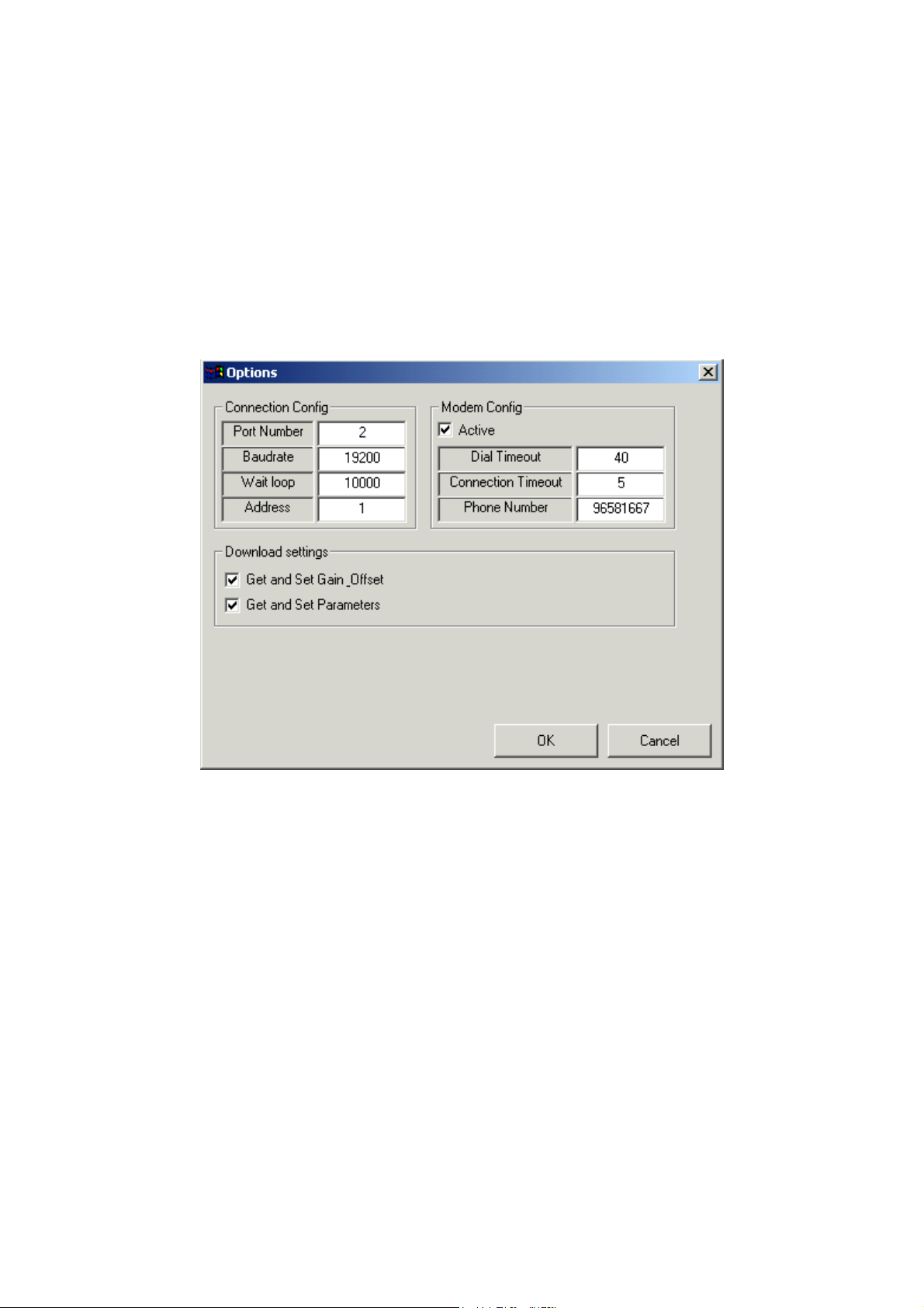
Installation
1. Select the CD drive by double-clicking on it.
2. When the window opens find and double-click on the file "setup.exe"
3. This will launch the installer, follow the on-screen instructions.
Using XPCS
Configuring the Program
On 'XPCS' main window, press the 'Options' button; the 'Options' Box opens.
Configuring Communication Settings
In 'Port Number' text box type serial port number connected to the PCS Target platform,
or modem port number to remotely connection.
In 'Baudrate' text box type the PCS Target platform Baudrate. Usually the value is:
19200.
'Wait loop' is a communication time error counter. To fix communication problems with
remote targets via modem, try to insert greater value.
In the 'Address' text box, insert the PCS Target address.
Page 93 of 105 pages
Page 98

Modem Configurations
To connect to the remote target via a modem, select 'Active' check box in 'Modem
Config' frame.
'Connection Timeout' is the waiting time in seconds to request data from the PCS target
platform. If no data is retrieved from the target after the waiting time, the program
generates a communication time error.
'Dial Time Out' is a waiting time in seconds to be used by the local modem trying to
connect to the remote modem. After this time has elapsed, the program generates a
timeout error.
'Phone Number' is the phone number dialed to a specific destination.
Download Setting Configuration
If 'Get and set Gain Offset' are checked, when the program downloads, all gain and
offset values will be stored before PCS code downloading, and restored after
downloading is completed.
If 'Get and Set Parameters' are checked, when the program downloads, all parameters
will be stored before PCS code downloading and restored after downloading is
completed.
Note:
The program stores parameters only in these conditions:
• CAT Technologies ADMC Program Installed on PC.
• The Downloaded file (DWN) has the same name as one of the ADMC type
files (for example if downloaded file name is: LabTN2.DWN, the ADMC file is
compatible, because ADMC type files: LabTN2.mdb exists).
Note:
Only current selected Program (For example: 1-Instruments) parameters will be
saved and restored.
Note:
Note:
Because the PCS target platform parameters saving process are complex,
restoring Parameters task takes long time (few minutes)!
There is no need to edit options every time that the program starts running. The
program saves the settings by pressing the 'OK' button and starts up with the
last settings.
Page 94 of 105 pages
Page 99
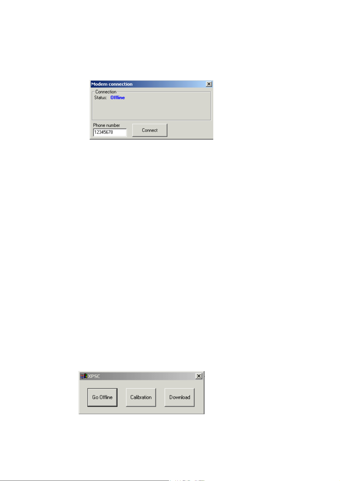
Connecting to the PCS Target platform
The program can be connected to the PCS Target by a RS232 serial cable, or via a
modem. If the program is configured to perform a connection via a modem (Modem
Active selected), pressing the 'Go Online' button on the main XPCS window will display
the 'Modem connection' dialog box:
By pressing the 'Connect' button, the program will try to connect to the remote PCS
Target. Opening connection between remote PCS Target and PC performs the following
tasks:
1. Check if COM Port is available.
2. Detect modem.
3. Dial a phone number.
4. Wait for a connection establishment.
5. Check if remote target platforms are connected.
If one of the tasks fails, the program will abort and the connection process will display
the relevant error message.
If the 'Modem active' option is not selected, by pressing the 'Connect' button, the
program will open the communication port. In this case, communication establishment
tasks will be:
6. Check if COM Port is available.
7. Open COM Port.
Note:
In this case the program is not checking if the target platform is connected.
After a connection is established, the main XPCS window will be displayed.
When program is online, the 'Go offline', 'Calibration' and 'Download' buttons will be
displayed.
Page 95 of 105 pages
Page 100
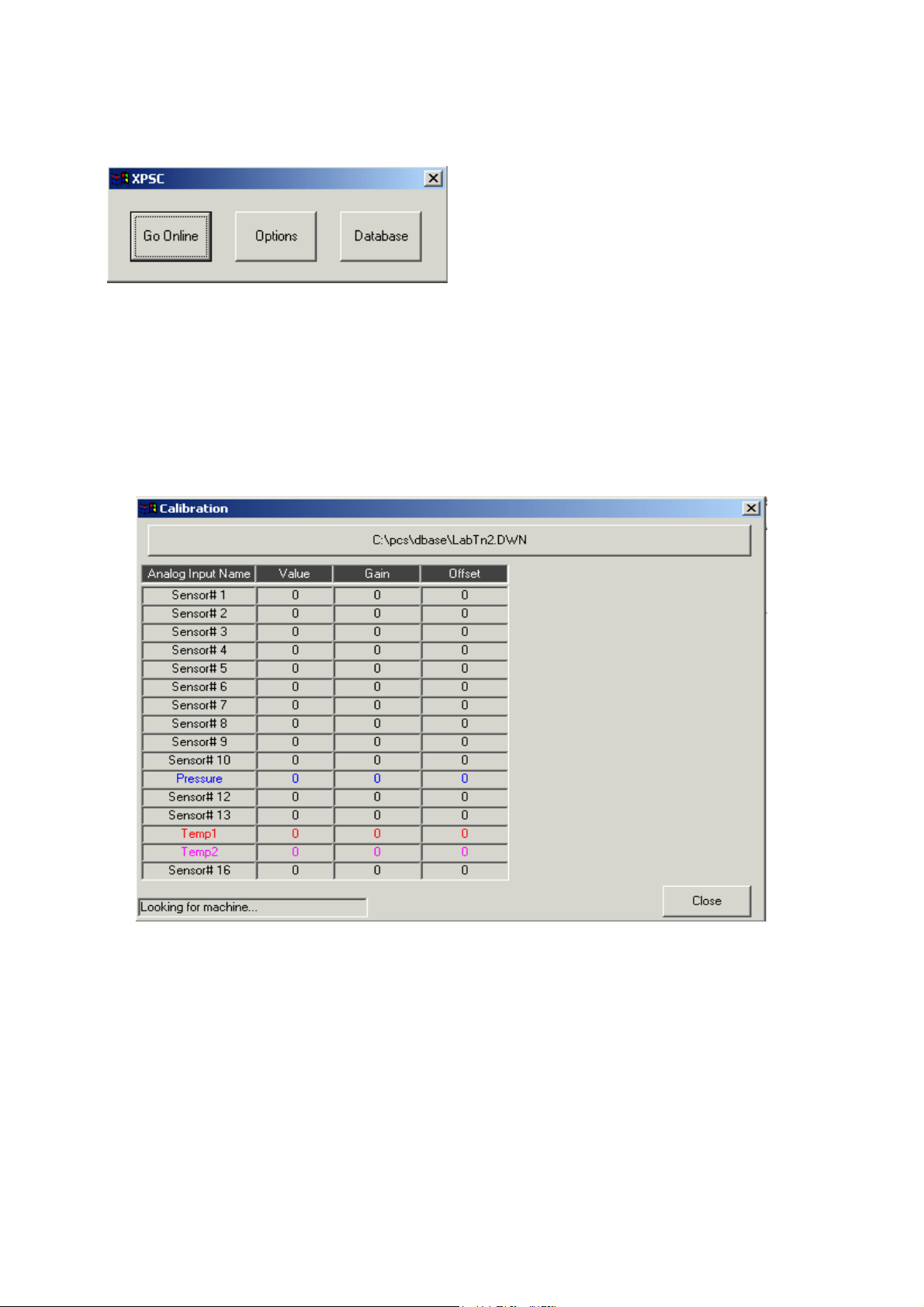
Pressing the 'Go Offline' button will close the current connection and buttons 'Go
Online', 'Options' and 'Database' will be displayed on the main XPCS window:
Pressing the 'Calibration' button will display the 'Calibration' window.
Pressing the 'Download' button will display 'Download' window.
Calibration Window
The calibration window will try to connect with the PCS Target platform.
The connection tasks are:
8. Check if target is connected. In the status bar "Looking for machine…"
is displayed.
9. Upload all 16 analog inputs Gain and Offset values. In the status bar
Uploading gain & offset…" is displayed.
10. Uploading analog inputs values. In the status bar "Connected" is
displayed. This task is performed periodically every 500 milliseconds.
This allows real time refreshing of the analog inputs values.
Page 96 of 105 pages
 Loading...