

Tuttnauer 2340 M, 3850 M, 3140 M, 1730 M, 2540 M Technician Manual
...
TECHNICIAN
MANUAL
Table -Top Autoclaves
models 1730, 2340, 2540, 3140, 3850, 3870 M & MK
1730MK Valueklave
Cat. No. MAN205-0309001EN Rev. H
Tuttnauer Europe b.v., Paardeweide 36, 4824 EH, Breda, P.O. Box 7191, 4800 GD Breda, Netherlands. +31/76-5423510, Fax: +31/76-5423540


1
TABLE OF CONTENTS
PARAGRAPH PAGE NO.
1 INTRODUCTION ........................................................................................3
2 PERIODICAL TESTS ................................................................................. 3
3 SYMBOL DESCRIPTION ........................................................................... 3
4 SAFETY INSTRUCTIONS.......................................................................... 4
5 WATER QUALITY ......................................................................................5
5.1 Water for Generating Steam .............................................................5
5.2 Reverse Osmosis................................................................................5
6 MAINTAINING AND REPLACING PARTS ...........................................10
6.1 Safety Tests after Repair .................................................................10
6.2 Dismantling the Outer Cover of the Autoclave............................... 11
6.3 Cleaning and Replacing Air Trap Jet.............................................12
6.4 Replacing the Safety Valve .............................................................13
6.5 Replacing the circuit breaker.......................................................... 14
6.6 Temperature Safety Thermostat...................................................... 15
6.7 Raising the Working the Temperature of the Safety Thermostat... 15
6.8 Cut-Off Thermostat ......................................................................... 16
6.9 Replacing Heating Elements...........................................................17
6.10 Replacing Multi-Purpose Valve ...................................................... 18
6.11 Unclogging the multi-Purpose Valve or Chamber .........................20
6.12 Pressure Door Lock System ............................................................20
6.13 Replacing the Door Bellows............................................................21
6.14 Replacing the thermostat B10.........................................................22
6.15 Replacement of the Door Cover......................................................23
6.16 Replacing the Locking Device ........................................................25
6.17 Replacing the Door Switch (models 2540, 3150, 3850, 3870) ........26
6.18 Replacing the Drain Valve .............................................................. 27
7 TROUBLESHOOTING .............................................................................28
8 LIST OF SPARE PARTS........................................................................... 36
9 PRESSURE VS TEMPERATURE FOR SATURATED STEAM ............. 40

2
TABLE OF CONTENT (Cont.)
DRAWINGS PAGE NO.
Front View Model 1730 M, MK-Valueklave................................................................6
Front View Model 2340/2540 M, MK ..........................................................................7
Front View Model 3850/3870 M, MK ..........................................................................8
Rear View ......................................................................................................................9
General View of Vessel, Door and Accessories .........................................................32
Autoclave Cover ..........................................................................................................33
Door Tightening Bolt – Assembly ..............................................................................34
Multi-Purpose Valve Assembly................................................................................... 35
Drawing of Electrical System of Table Autoclave Models 1730M, MK ...................44
Drawing of Electrical System of Table Autoclave Models 2340/2540 M, MK .........45
Drawing of Electric System of Table Autoclave Model 3140 M ...............................46
Drawing of Electric System of Table Autoclave Models 3850 M.............................. 47
Drawing of Electrical System of Table Autoclave Models 3870 M...........................48
Piping Diagram Table Top Autoclave Models: M and MK ......................................49
3
1 INTRODUCTION
This manual, together with the operator’s manual, forms the complete edition
of the Operation and Maintenance instructions. This manual is intended for the
use of the technician. It is forbidden for unqualified and unauthorized
personnel to service the autoclave in accordance with the instructions in this
manual. Any unauthorized service may result in the invalidation of the
manufacturer’s guarantee.
The qualified technician shall be an authorized electrician with the right
qualifications in electronics and shall be familiar with the local
technical/electrical regulations.
2 PERIODICAL TESTS
PERIOD TEST
1 months Test the safety valve by operating it.
6 months
Remove the autoclave’s cover, tighten the heaters’ screws and
electrical connections and valves.
Check the continuity of the grounding connections.
Perform validation of the autoclave.
Check the precise operation of the earth leakage relay.
Check that the autoclave is leveled.
Check the safety elements; safety valve, door locking bellows and
door locking mechanisms.
Run the autoclave and verify that it operates as specified.
Check the water reservoir, piping, plastic parts and electric wires.
Check and tighten the piping joints to avoid leakage.
Check and tighten all screw connections, heaters and valves and
instrumentation.
Year
Calibrate the temperature and pressure once a year or in reference to
local rules or regulations (refer to the section on Calibration).
5 years Observe the closing device for excessive wear
Safety tests (pressure vessel, efficiency, electrical) shall be performed in
accordance with local rules or regulations, by an authorized inspector.
Only an authorized technician shall perform the 6-months and yearly tests!
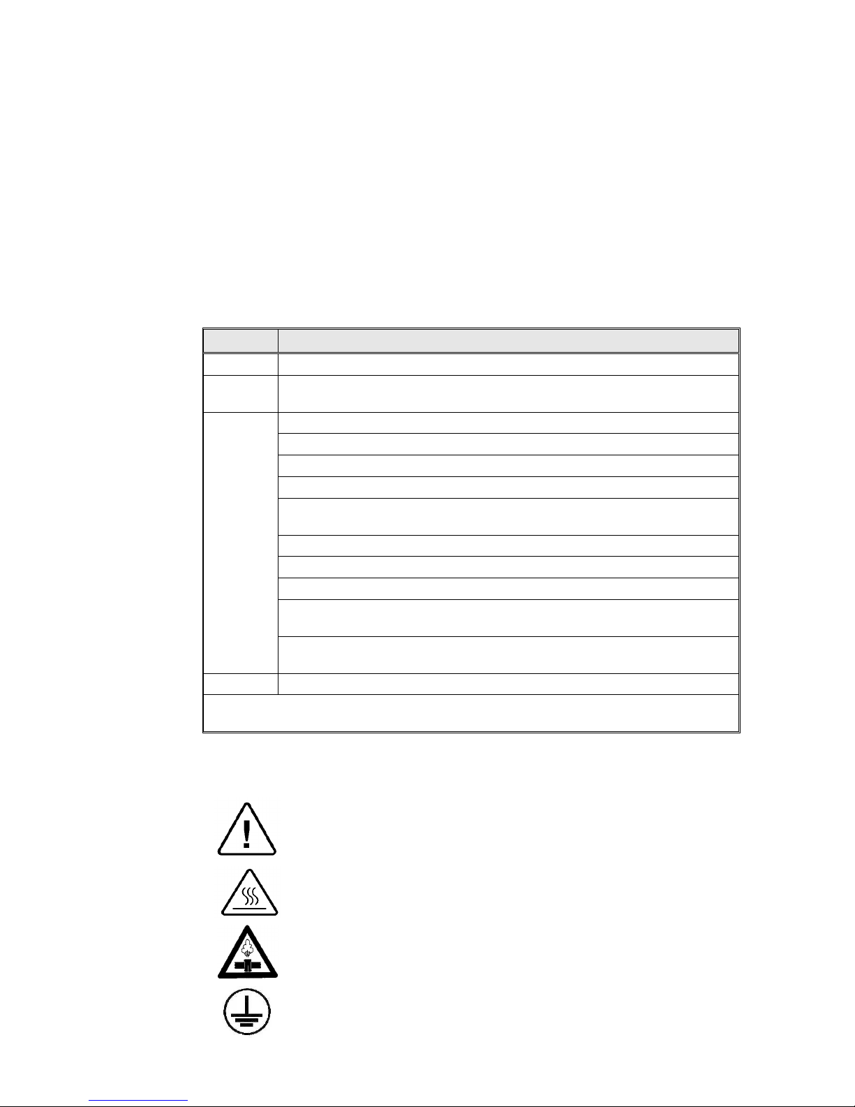
3 SYMBOL DESCRIPTION
Caution! Consult accompanying documents
Caution! Hot Surface.
Caution! Hot steam.
Ground

4
4 SAFETY INSTRUCTIONS
The autoclave has unique characteristics. Please read and understand the
operation instructions before first operation of the autoclave. The following
issues may require instructions guidance provided by the manufacturer: how to
operate the autoclave, the door safety mechanism, the dangers involved in
circumventing safety means, how to ensure that the door is closed, and how to
select a correct sterilization program.
Autoclave maintenance is crucial for the correct and efficient function of the
device. We enclose a log booklet that includes maintenance recommendations,
with every device.
1. Make sure that you know where the main power switch is.
2. Never use the autoclave to sterilize corrosive products, such as: acids,
bases and phenols, volatile compounds or solutions such ethanol,
methanol or chloroform nor radioactive substances.
3. All autoclave users must receive training in proper usage from an
experienced employee. Every new employee must undergo a training
period under an experienced employee.
4. A written procedure must be established for autoclave operation,
including: daily safety tests, seal inspection and door hinge inspection,
smooth action of the closing mechanism, chamber cleaning, prevention
of clogging and preservation from corrosion, what is permitted and what
is prohibited for sterilization and choosing a sterilization program.
5. Before use, check inside the autoclave chamber to ensure that no items
have been left from the previous cycle.
6. Load trays in such a way as to allow steam to move freely among all
items.
7. Do not attempt to sterilize liquids since this autoclave is not intended to
sterilize liquids.
8. When sterilizing plastic materials, make sure that the item can withstand
sterilization temperature. Plastic that melts in the chamber is liable to
cause a great deal of damage.
9. On closing the device door, make sure it is properly locked before
activating.
10. Verify once again that you have chosen the appropriate sterilization
program.
11. Before withdrawing trays, wear heat resistant gloves.
12. Before opening the door, verify that there is no pressure in the chamber
(chamber pressure gauge is located on the autoclave's front panel).
13. Open the door slowly to allow steam to escape and wait 5 minutes
before you remove the load.
14. Once a month, ensure that the safety valves are functioning, and once
annually a certified tester must conduct pressure chamber safety tests.
15. Once annually, or more frequently, effective tests must be performed,
i.e., calibration and validation.
16. Examine the condition of assemblies on a regular basis. Make sure there
are no leaks, breaks, blockages, whistles or strange noises.
17. It is required to conduct maintenance operations as instructed.
18. Immediately notify the person in charge of any deviation or risk for the
proper function of the device.
5
5 WATER QUALITY
5.1 Water for Generating Steam
The distilled or mineral – free water supplied to the sterlizer shall be
according to the table below:
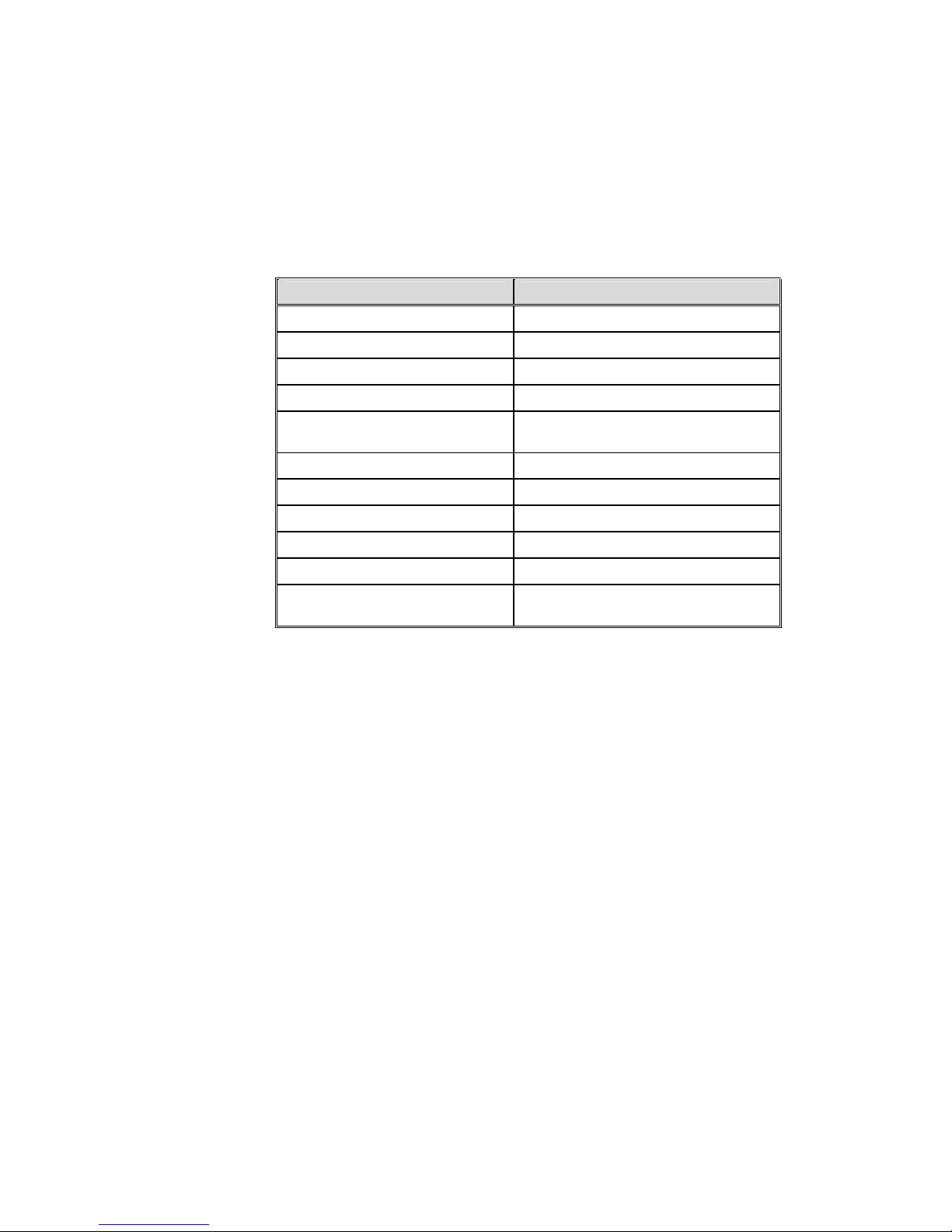
Physical Characteristics and Maximum acceptable contaminants
levels in steam for sterlizers
(According to EN 13060:2004).
Element Condensate – allowable content
Silicium oxide. SiO
2
≤0.1 mg/kg
Iron ≤0.1 mg/kg
Cadmium ≤0.005 mg/kg
Lead ≤ 0.05 mg/kg
Rest of metals except iron,
cadmium, lead
≤0.1 mg/kg
Chloride (Cl) ≤0.1 mg/kg
Phosphate (P2O5) ≤0.1 mg/kg
Conductivity (at 20°C) ≤3 μs/cm
pH value (degree of acidity) 5 to 7
Appearance Colourless clean without sediment
Hardness (Σ Ions of alkaline
earth)
≤0.02 mmol/l
Compliance with the above data should be tested in accordance with
acknowledged analytical methods, by an authorized laboratory.
Attention:
We recommend testing the water quality once a month. The use of
water that does not comply with the table above may have severe
impact on the working life of the sterilizer and can invalidate the
manufacturer’s guarantee.
5.2 Reverse Osmosis
A Reverse Osmosis system may be used to improve the quality of the
water used to generate steam in the autoclave chamber. The use of
mineral free will contribute to better performance and longer life of the
autoclave.
6
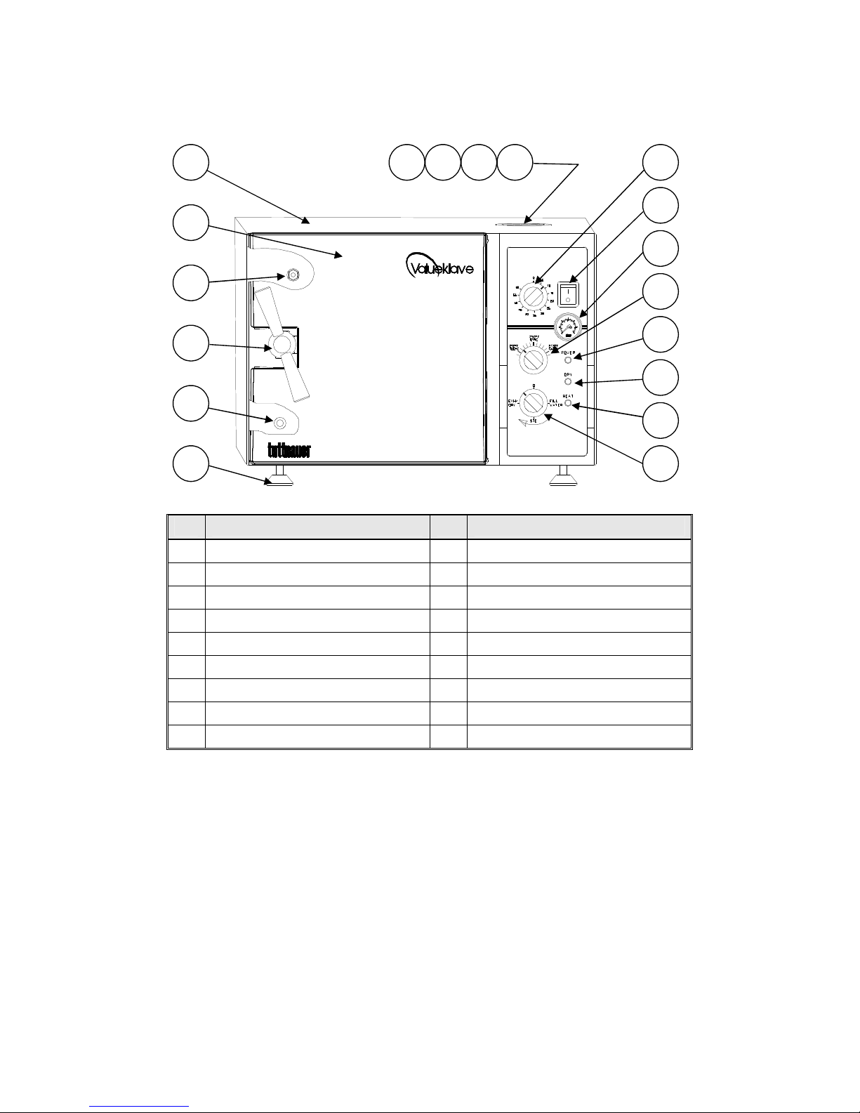
FRONT VIEW MODEL 1730 M, MK-Valueklave
No. description No. description
1. Water reservoir cover 10. Dry indicator light
2. Water reservoir 11. Heat indicator light
3. Safety valve 12. Multipurpose valve
4. Air trap jet 13. Front legs
5. Timer 14. Reservoir water drain valve
6. Main power switch 15. Door Closing Device
7. Pressure gauge 16. Door Micro-switch
8. Thermostat (B10) knob 17. Door cover
9. Power indicator light 18. Autoclave cover
14
131112
8910
5
6
7
18171234
1
6
15
7
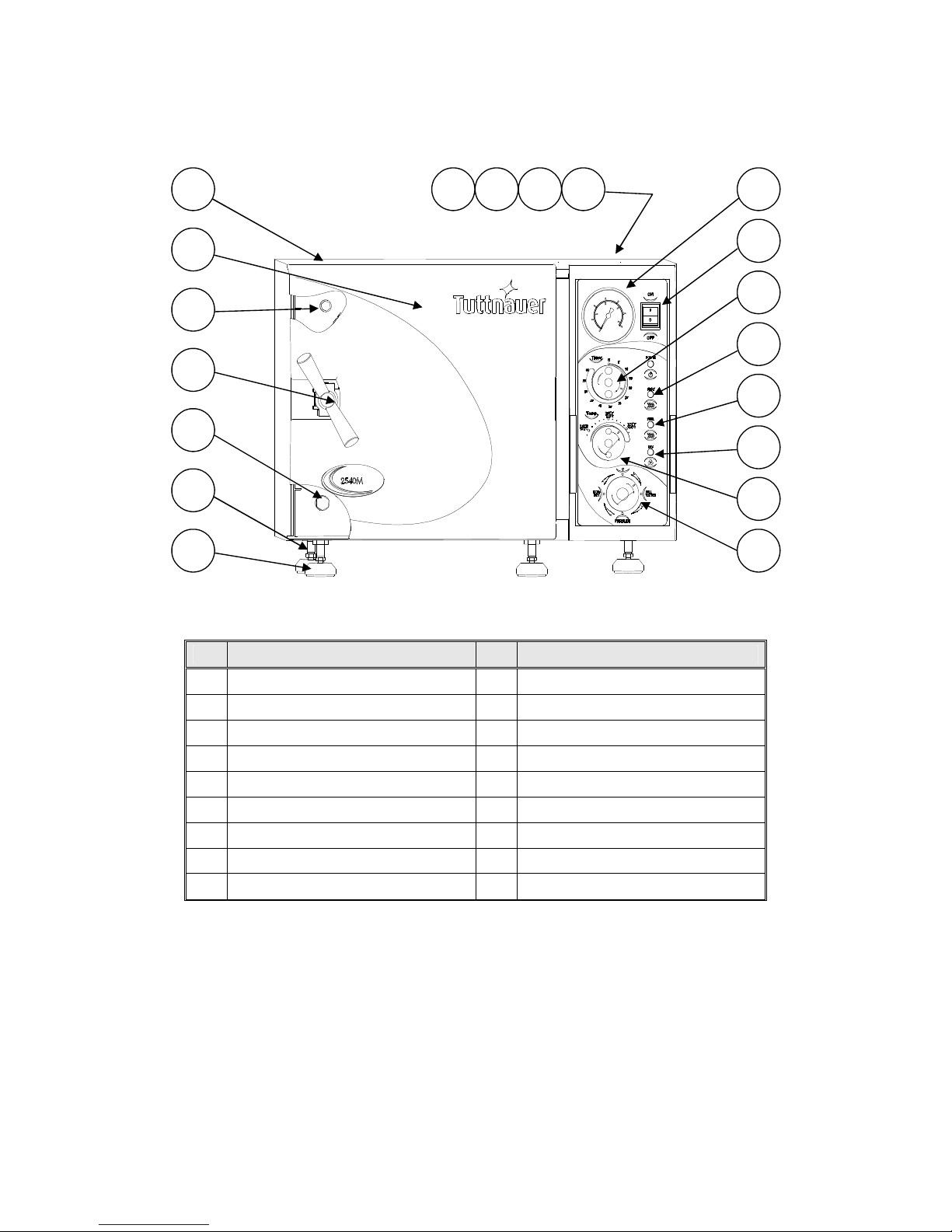
FRONT VIEW MODEL 2340/2540 M, MK
No. description No. description
1. Water reservoir cover 10. Heat indicator light
2. Water reservoir 11. Thermostat (B10) knob
3. Safety valve 12. Multipurpose valve
4. Air trap jet 13. Front legs
5. Pressure gauge 14. Rear legs
6. Main power switch 16. Door Closing Device
7. Timer 18.
Door cover
8. Power indicator light 19. Autoclave cover
9. Dry indicator light
16
14
13
11
12
8
9
10
5
6
7
19
18
1 2 3 4
17
15

8
FRONT VIEW MODEL 3850/3870 M, MK
No. description No. description
1. Water reservoir cover 10. Heat indicator light
2. Water reservoir 11. Thermostat (B10) knob
3. Safety valve 12. Multipurpose valve
4. Air trap jet 13. Front legs
5. Pressure gauge 14. Reservoir water drain valve
6. Main power switch 15. Door Closing Device
7. Timer 16. Door Micro-switch
8. Power indicator light 17. Door cover
9. Dry indicator light 18. Autoclave cover
14
13
11
12
8
9
10
5
6
7
18
17
1 2 3 4
16
15
9
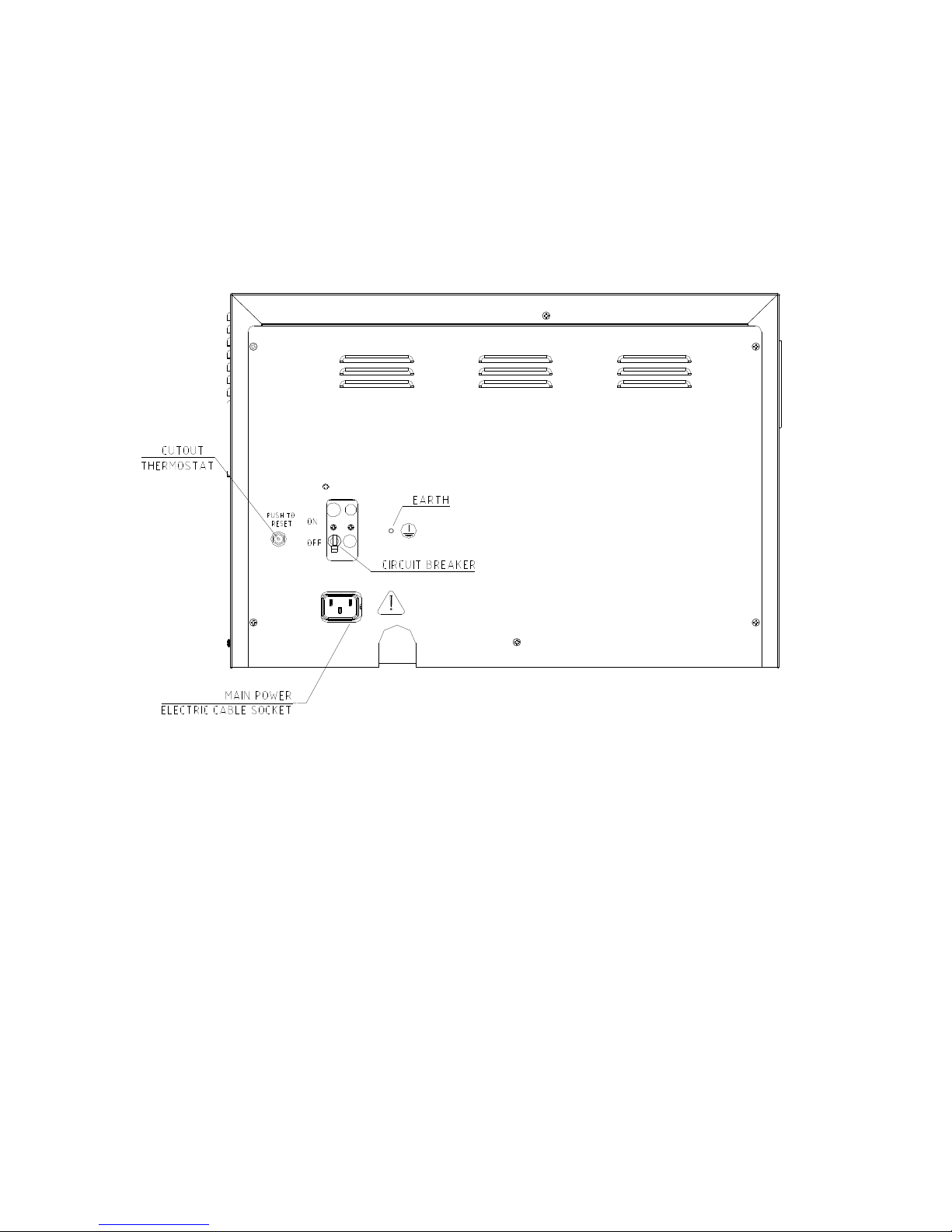
REAR VIEW

10
6 MAINTAINING AND REPLACING PARTS
6.1 Safety Tests after Repair
ATTENTION!
After every repair or dismantling the enclosure, the autoclave
should pass two safety electrical test by the Service Engineer. The
following shall be performed:
Warning!
When re-installing the enclosure, connect the earthing to the cover.
On installing the rear cover, connect the earthing before
accomplishing the installation of the rear cover.
6.1.1 Enclosure Leakage Current Test.
Every autoclave should pass this test as follows:
1. Connect the electrical cord to the autoclave.
2. Turn on the main switch and the circuit breaker.
3. Short-circuit the L and N pins on the cord's plug.
4. Connect the Short-circuit pins to the L pole on the Megger.
5. Connect the earth pins to the earth pole on the Megger.
6. Impose an electrical potential of 500-1000V on the tested
autoclave. The insulation resistance should be at least 2
M
Ω.
The test is successful if there was no leakage.
6.1.2 Protective Earth Impedance Test
1. Connect the grounding pin of the power cord plug to one
pole of an Ohmmeter.
2. Connect any other metallic part (preferable – the metallic
part of the locking screw) to the second pole of the
Ohmmeter.
3.
The resistance should not exceed 0.3 Ω.
After performing these tests, the Service Engineer should complete and
sign the Work Order.
11
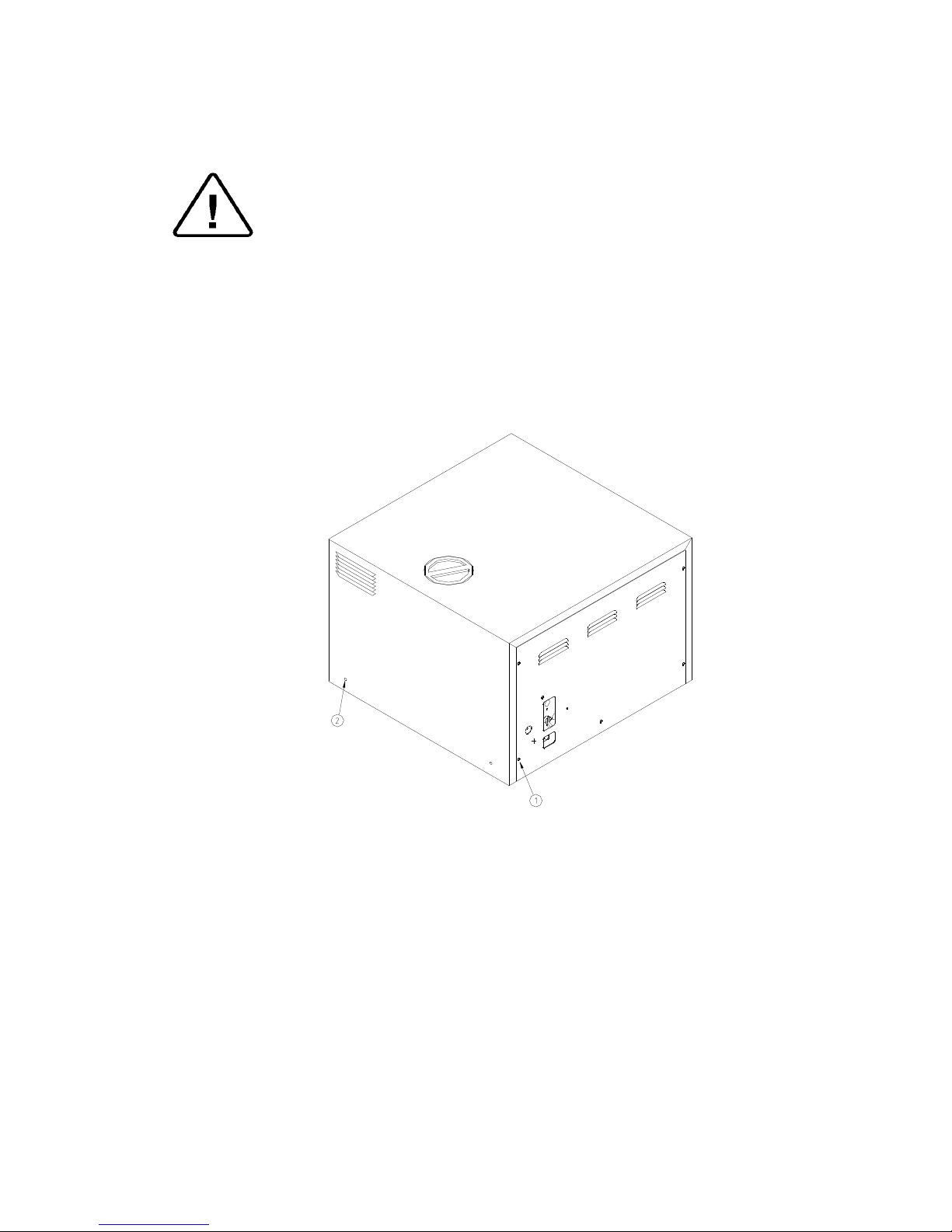
6.2 Dismantling the Outer Cover of the Autoclave.
Caution:
Allow the instrument to cool before removing the outer covers.
Warning:
Before starting disconnect the instrument from the power source
and make sure there is no pressure in the autoclave.
Then proceed as follows:
1. Remove the screws holding the rear cover (1).
2. Remove the screws holding the cover to the base (2).
3. Pull the cover upwards.
12
6.3 Cleaning and Replacing Air Trap Jet
(Located in the water reservoir)
The elimination of air pockets from the sterilization chamber during
heating and sterilization phases is achieved by means of the air trap jet.
This device consists of a small orifice that is obtrusive and opened by a
small wire moving forth and back.
The air pockets and small steam quantities are pushed up by the steam
pressure and evacuated through this orifice.
Caution:
Before starting, ensure that the electric cord is disconnected and
that there is no pressure in the autoclave.
1. Remove the water reservoir cover.
2. Clean the hole of the jet by manipulating the air trap wire back and
forth (A).
3. In case it is necessary to replace the air trap jet, allow the
instrument to cool and the pressure to drop to 0 before removing
the jet.
It is important to clean the hole of the air trap, as described at point 2
before starting operation of the autoclave, for the first time.
13
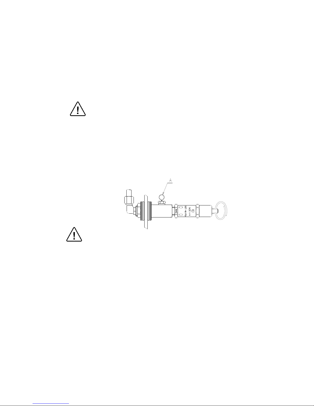
6.4 Replacing the Safety Valve
Caution
Before starting, be sure that the electric cord is disconnected and that
there is no pressure in the autoclave.
Note:
These instructions are valid for both, CE-marked and ASME type
safety valves.
1. Remove the water reservoir cover.
2. Unscrew the safety valve and remove it from the safety valve base.
3. Replace it with a new safety valve (ensure the safety valve is an
original one!)
4. Test all autoclave.
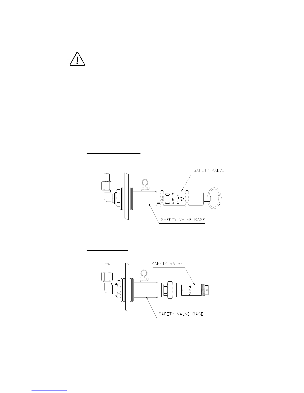
ASME approved Type
CE marked Type
14
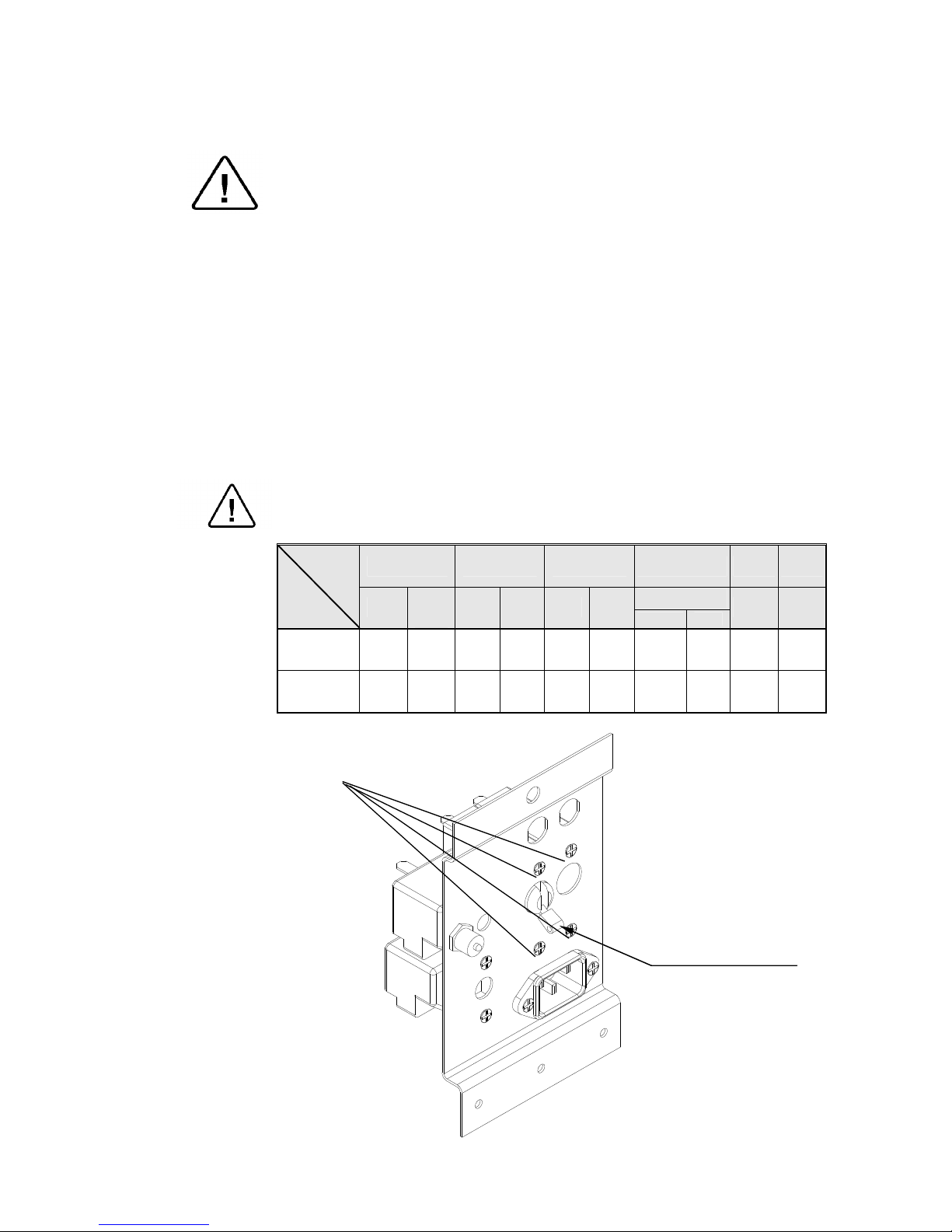
6.5 Replacing the circuit breaker
Caution!
Before starting, disconnect the instrument from the power source.
1. Remove the autoclave cover (see para. 6.2 “Dismantling the Outer
Covers of the Autoclave”).
2. Disconnect the wires from the circuit breaker.
3. Remove the four screws connecting the circuit breaker to the panel (1).
4. Replace the circuit breaker with a new one.
5. Reconnect the electrical wires.
6. Reassemble the cover.
7. Turn on the autoclave and verify it operates correctly.
8. Move the circuit breaker’s lever to the “tripped” position and verify
that the autoclave turns off.
Make sure that the correct circuit breaker is installed as marked in
the table below!
1730 2340 2540 3140 3850 3870
M
Model
Voltage
M
MK
MK
-V
M MK M MK
standard special
M M
1ph,
120V,
50/60 Hz
15 A 15 A 15 A — 15 A — — — — —
1ph,
230V,
50/60 Hz
10 A 10 A 10 A 15 A 10 A 15 A 10 A 15 A 15 A 15 A
Circuit breaker lever
 Loading...