

Page 1

TECHNICIAN
MANUAL
Electronic Table - top
Pre and Post Vacuum Autoclaves
models 2540 & 3870 EHS
Cat. No. MAN205-0063-005E Rev. D
Page 2

1
TABLE OF CONTENTS
PARAGRAPH PAGE NO.
1 INTRODUCTION..................................................................................................4
2 SYMBOL DESCRIPTION ....................................................................................4
3 INSTALLATION INSTRUCTIONS .....................................................................5
3.1 Site requirements for installation of a 2540 EHS
.......................................
5
3.2 Site requirements for installation of a 3870 EHS
.......................................
6
3.3 Suggested Site Drain Drawing
.....................................................................
7
3.4 Electrical Specifications
...............................................................................
8
3.5 Placing the Autoclave
...................................................................................
8
3.6 Connections to Utility Supplies
....................................................................
8
3.7 Installation Tests
........................................................................................
10
3.8 Water Quality
..............................................................................................
11
4 DESCRIPTION OF THE CONTROL SYSTEM. ..............................................12
4.1 System Summary
........................................................................................
12
4.2 Keyboard
.....................................................................................................
13
4.3 Digital Board DIG - T2
..............................................................................
13
4.4 Analog Board ANL-T2
...............................................................................
15
4.5 AC - Board - AC-T1
....................................................................................
17
5 CALIBRATION OF PRESSURE AND TEMPERATURE ...............................19
5.1 Calibration Overview
..................................................................................
19
5.2 Calibration Theory - Error Compensation:
..............................................
20
5.3 Equipment needed for calibration
.............................................................
20
5.4 Calibration Procedure
................................................................................
20
6 TESTING AND RESETTING.............................................................................26
6.1 Test Points
...................................................................................................
26
6.2 In – Out Test mode:
....................................................................................
27
6.3 Resetting the Autoclave:
.............................................................................
28
6.4 Input Output Graph:
..................................................................................
29
7 PROPERTIES OF SATURATED STEAM ........................................................ 35
8 SOFTWARE PROGRAMMING PARAMETERS .............................................36
8.1 General
........................................................................................................
36
8.2 Changing Parameters
.................................................................................
36
9 MAINTENANCE AND REPLACEMENT PROCEDURES .............................47
9.1 Safety Tests after Repair
............................................................................
47
9.2 Removing the Autoclave’s Outer Covers
...................................................
48
9.3 Replacing the Safety Valve
.........................................................................
49
Page 3

2
TABLE OF CONTENT (Cont.)
PARAGRAPH PAGE NO.
9.4 Replacing the DIG-T2 board
......................................................................
50
9.5 Drain Valve Repair
.....................................................................................
52
9.6 Replacing the Pressure Gauge
...................................................................
54
9.7 Replacing the Door Bellows (Located in the door bridge)
........................
55
9.8 Replacing the Printer
.................................................................................
56
9.9 Replacing the Door Switch
.........................................................................
57
9.10 Replacing the circuit breaker
.....................................................................
58
9.11 Replacing the water pump
..........................................................................
59
9.12 Pressure Switch
..........................................................................................
60
9.13 The Heaters
.................................................................................................
61
9.14 The Dual Compartment Water Reservoir
..................................................
62
9.15 The Water Sensing Electrodes
...................................................................
64
9.16 The Vacuum Pump
.....................................................................................
66
9.17 Draining the Jacket
....................................................................................
68
9.18 Replacement of the Door Cover
.................................................................
69
9.19 Replacing the Closing Device
....................................................................
70
9.20 PT100 Temperature Sensor Replacement
.................................................
71
10 TROUBLESHOOTING .......................................................................................72
10.1 Preliminary Check
......................................................................................
72
10.2 Preliminary Troubleshooting
.....................................................................
73
10.3 Pre-process malfunction
............................................................................
79
10.4 In Process Malfunction
..............................................................................
84
10.5 Mechanical malfunction
..........................................................................
111
10.6 Water pump malfunction
.........................................................................
113
11 SPARE PARTS LIST......................................................................................... 114
12 VALVES NUMBERING....................................................................................124
Page 4

3
TABLE OF CONTENT (Cont.)
DRAWINGS PAGE NO.
REAR VIEW
..................................................................................................................
9
CONTROL SYSTEM BLOCK – DIAGRAM
............................................................
12
DIG- T2 BOARD
.........................................................................................................
14
ANL- T2 BOARD
........................................................................................................
16
AC-T1 BOARD
............................................................................................................
18
EXTERNAL CONNECTION OF THE 2540EHS AUTOCLAVES
ELECTRONICS
BOX
...............................................................................................
117
EXTERNAL
CONNECTION OF THE 3870EHS AUTOCLAVES
ELECTRONICS BOX
...............................................................................................
118
VESSEL ASSEMBLY
...............................................................................................
118
VESSEL ASSEMBLY
...............................................................................................
119
OUTER CABINET – ASSEMBLY
...........................................................................
120
TRAY HOLDER
........................................................................................................
121
TRAY
.........................................................................................................................
122
TRAY HANDLE (CMT240-0001)
............................................................................
122
DOOR TIGHTENING BOLT – ASSEMBLY
..........................................................
123
PIPING DRAWING FOR 2540 EHS
.......................................................................
125
PIPING DRAWING FOR 3870 EHS
.......................................................................
126
ELECTRICAL DRAWING FOR 2540 EHS
............................................................
127
ELECTRICAL DRAWING FOR 3870 EHS (TILL S/N 2307039)
..........................
128
ELECTRICAL DRAWING FOR 3870 EHS (AFTER S/N 2307040)
......................
129
Page 5

4
1 INTRODUCTION
This Technician’s Manual, together with the Operator’s Manual, forms the
complete set of Operation and Maintenance instructions for the EHS pre and
post vacuum autoclave. This manual is intended for the use of the technician.
It is strongly recommended that only qualified and Tuttnauer factory trained
personnel service this autoclave and do so in accordance with the instructions
in this manual. Any unauthorized service may result in the invalidation of the
manufacturer’s warranty.
2 SYMBOL DESCRIPTION
Caution! Consult accompanying documents
Caution! Hot surface.
Caution! Hot steam.
Protective earth (Ground)
Stand by
Page 6

5
3 INSTALLATION INSTRUCTIONS
For proper operation, these are the required utilities that need to be
supplied for each model EHS:
3.1 Site requirements for installation of a 2540 EHS
Caution
The sterilizer must be placed on a rigid and leveled surface and
must be able to hold the weight of the device and loaded material.
1. Counter top able to support a minimum 200 lb. * (the unit is
shipped with a suitable stand - 26”W x 33”D x 34”H)
2. Counter space minimum 20”W x 32”D x 20”H * (see unit
dimensions below)
3. City water supply 15 - 58 psi with shut off valve having ½" NPT
male end.
Higher rates of pressure will require the installation of a pressure
reducer (58 psi max).
A regulator and pressure gauge are supplied with the unit
The minimum flow rate required is 0.66 gal/min. (2.5 lit./min.).
Installation of the valve should be 2" above counter height at the
rear of the unit.
4. Mineral Free water supply 7 - 30 psi with shut off valve and ½"
NPT male end.
Higher rates of pressure will require the installation of a pressure
reducer.
A regulator and pressure gauge are supplied with the unit
The minimum rate of flow is 0.26 gal/min (1 lit/min).
Installation of the valve should be 2" above counter height at the
rear of the unit. * (an optional R.O. water system is available).
5. Electrical power 20A – 208V single phase. Connection required;
flush mount receptacle 6-20R, within 1 foot of the rear of the unit.
6. Drainage should be to a 4” high 4” diameter air break, reducing
down to a 1 ½” vented line with a trap. All drainage components
must be able to withstand a non-continuous temperature of 140°F
(60°C). Drain opening should be within 1 foot of the rear of the
unit and no higher than 16” above the floor. The use of two ½”x 6"
Milford Type Copper Coated Hangers is required for the
positioning of the two drain hoses over the center of the air break
and a 4” metal worm gear clamp to secure the hangers. The hangers
will need to be bent at a 90º angle to allow for proper positioning
and securing with the clamp. * (see attached drawing)
Page 7

6
3.2 Site requirements for installation of a 3870 EHS
Caution
The sterilizer must be placed on a rigid and leveled surface and
must be able to hold the weight of the device and loaded material.
1. Counter top able to support a minimum 400 lb. * (the unit is
shipped with a suitable stand - 26”W x 33”D x 34”H)
2. Counter space minimum 26”W x 39”D x 24”H * (see unit
dimensions below)
3. City water supply 15 - 58 psi with shut off valve having ½" NPT
male end.
Higher rates of pressure will require the installation of a pressure
reducer (58 psi max).
A regulator and pressure gauge are supplied with the unit
The minimum flow rate required is 0.66 gal/min. (2.5 lit./min.).
Installation of the valve should be 2" above counter height at the
rear of the unit.
4. Mineral Free water supply 7 - 30 psi with shut off valve and ½"
NPT male end.
Higher rates of pressure will require the installation of a pressure
reducer.
A regulator and pressure gauge are supplied with the unit
The minimum rate of flow is 0.26 gal/min (1 lit/min).
Installation of the valve should be 2" above counter height at the
rear of the unit. * (an optional R.O. water system is available).
5. Electrical power 20A - 208V three phase, three power lines plus a
ground. Connection required; flush mount receptacle or drop line
with NEMA # L15-20R, this is a twist lock connector, within 1
foot of the rear of the unit.
6. Drainage should be to a 4” high 4” diameter air break, reducing
down to a 1 ½” vented line with a trap. All drainage components
must be able to withstand a non-continuous temperature of 140°F
(60°C). Drain opening should be within 1 foot of the rear of the
unit and no higher than 16” above the floor. The use of two ½”x 6"
Milford Type Copper Coated Hangers is required for the
positioning of the two drain hoses over the center of the air break
and a 4” metal worm gear clamp to secure the hangers. The hangers
will need to be bent at a 90º angle to allow for proper positioning
and securing with the clamp. * (see attached drawing)
Page 8
7
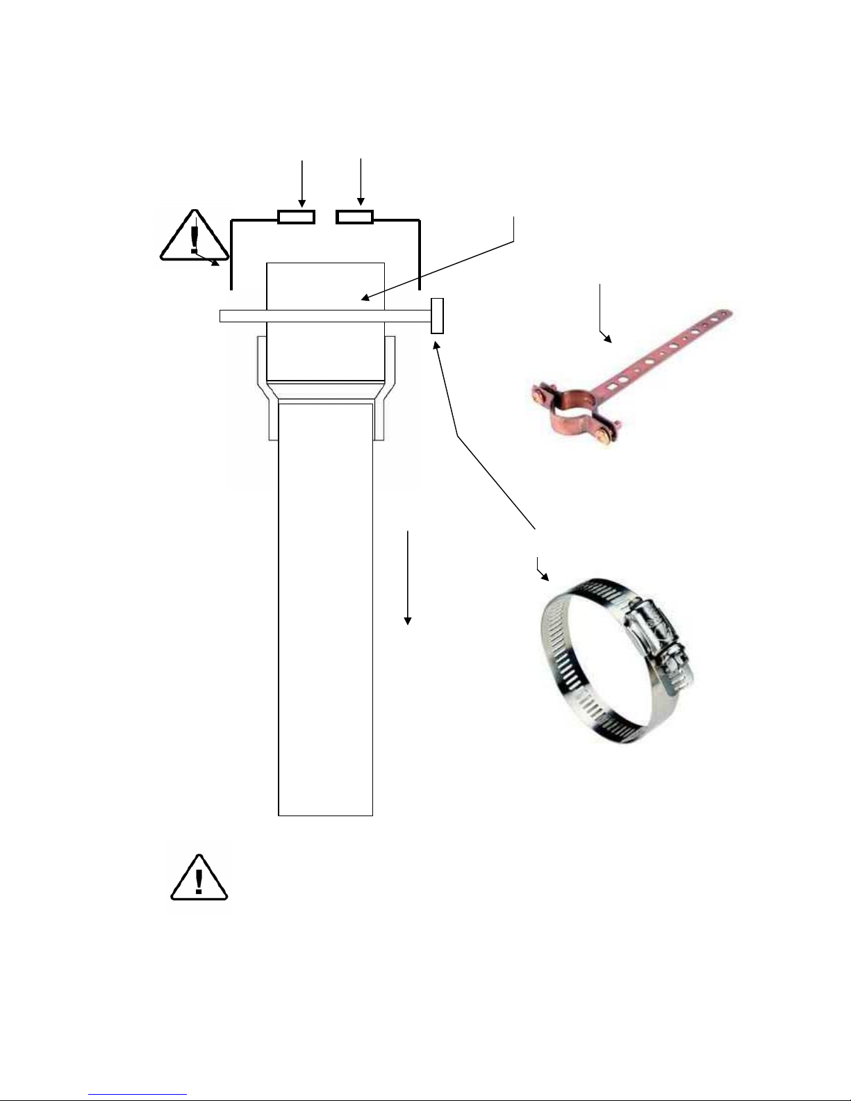
3.3 Suggested Site Drain Drawing
Caution!
Wastewater should be brought into the public sewage network in
accordance with the local rules or requirement i.e. only nonhazardous liquids shall be disposed of in public sewage!
Network and connection should comply with the devices
consumption, local installation and safety rules and regulations.
Discharge hoses from EHS
Hanger with
90º ben
d
Coated Hanger
4” x 4” PVC air brea
k
1 ½” PVC
To trap
4” Metal worm gear clamp
Milford Type Copper
Page 9
8
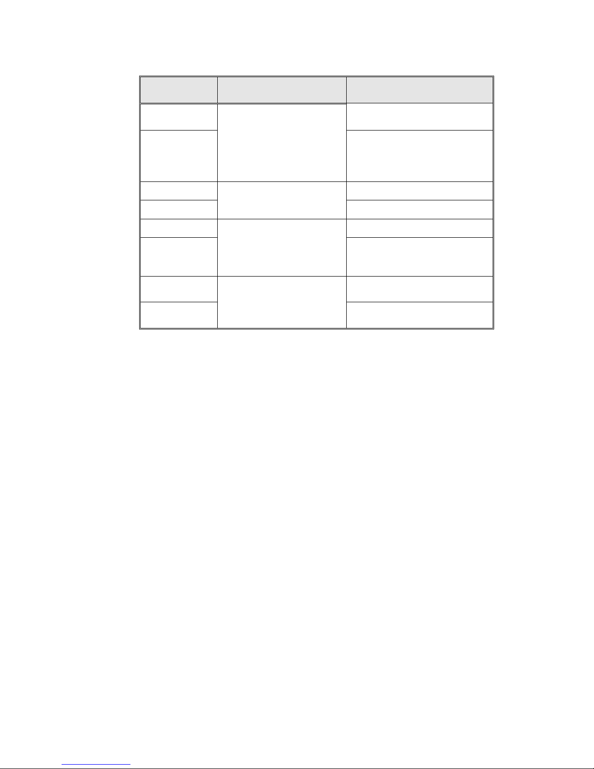
3.4 Electrical Specifications
Value
Property
2540 3870
Heaters Power 3000W 6000W
Total Power 3200W 6200W
Voltage (V) 1 ph / 208 3 ph / 208
Amperage (A) 15 15
Frequency (Hz) 50/60 50/60
Protection against electrical shock Class I (IEC 60601-1)
Note: In order to avoid any injury by electrical hazard, it is
recommended that a ground fault protection device be installed in
the electrical panel feeding the autoclave (local codes may make
this mandatory).
3.5 Placing the Autoclave
Set the rear legs so that the chamber pitches down in the front at a rate
of 1/8” per foot. This ensures that water is completely drained out of
the chamber through the opening at the bottom front of the chamber.
To check, pour a glass of water into the bottom rear of the autoclave
and observe the water flow out of the chamber.
NOTE: Keep the back and the sides of the autoclave
approximately 1” (25 mm) away from the wall to allow ventilation.
It is recommended that enough space be left around the autoclave
to give a technician access for servicing the machine.
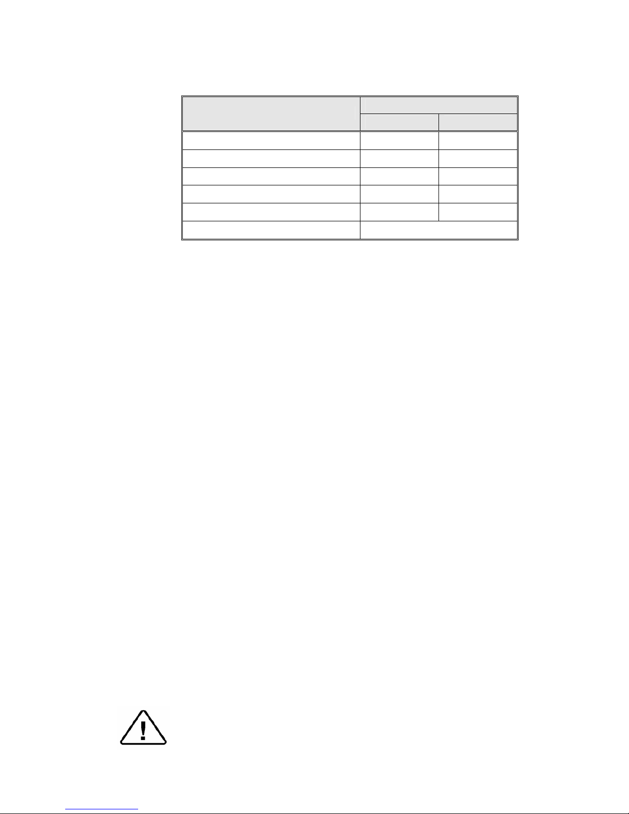
3.6 Connections to Utility Supplies
Using the ½” hoses and washers supplied with the unit
1. Connect the tap water inlet on the back of the autoclave to the feedwater supply (city water supply).
2. Connect the mineral -free water inlet on the back of the autoclave
to a source of mineral-free water.
3. Connect the exhaust outlet on the back of the autoclave (using the
black hose supplied with the unit) to a suitable drain as described
above. Be sure to observe local codes for discharge of this type.
Note:
The drain hose from the exhaust outlet must be fixed very
securely to the drain, ensuring that when steam and water are
exhausted the hose is not allowed to recoil and cause injury to
personnel.
4. Connect the reservoir overflow on the back of the autoclave to a
suitable drain as described above.
5. Plug the power cord into the supply socket.
Attention! The pressure of the jacket does not decrease when the
equipment is turned off.
Page 10
9
REAR VIEW
Page 11

10
3.7 Installation Tests
At the time of installation, before the autoclave can be okayed for
daily operation the service technician needs to perform the
following preliminary checks:
♦ Integrity check: perform a visual check to verify that there are no
dents, scratches or broken components on the autoclave
♦ The leakage current check: test the precise operation of the earth
leakage relay
♦ Ground check: test the continuity of the grounding connection
♦ Power supply check: check that proper power is being supplied to
the machine. See sec. 3.4.
♦ Pitch check: confirm that the autoclave has a downward pitch back
to front of 1/8" per foot. (see sec. 3.5)
♦ Exhaust and Feed hose check: ensure that all hoses are free
flowing and not restricted.
♦ Water Pressure Check: verify that the city water pressure into the
unit is between 15 - 58 psi. Verify that the mineral free water
pressure into the unit is between 7 - 30 psi.
♦ Door check: ensure that the door locking mechanism is
functioning properly
♦ Reset the Unit: turn power off using the green power button at the
bottom of the front panel, press and hold the Sel. Cycle button on
the keypad, turn power on, continue to hold the Sel. Cycle button
until the message Program Wait appears on the screen.
♦ Atmospheric Pressure check: the unit is set from the factory at
14.5 psia, this is atmospheric pressure at sea level. If the unit is
located more that 500 ft above or below sea level then the Atmos.
Press parameter must be set, see sec 8.2.17
♦ Safety Valve check: test the safety valve as per the instructions in
sec 8.6 of the Operator's Manual
♦ Cycle check: run a B&D Test to ensure that all systems in the unit
are functioning properly.
After the above steps are performed, the autoclave is ready for
daily operation
Page 12

11
3.8 Water Quality
3.8.1 Built-in Steam Generator
The distilled or mineral – free water supplied to the steam
generator shall be according to the table below:
A Reverse Osmosis system meeting the qualifications below
may be used to provide water for the steam generator. The
better the quality of the water, the better performance, the less
maintenance and the longer the life of the autoclave.
Mineral Free Water qualifications
(In compliance with ISO 11134 and ISO 13683)
Evaporate residue
≤ 15 mg/l
Silica
≤ 2 mg/l
Iron
≤ 0.2mg/l
Cadmium
≤ 0.005 mg/l
Lead
≤ 0.05 mg/l
Rest of heavy metals
≤ 0.1 mg/l
Chloride
≤ 3 mg/l
Phosphate
≤ 0.5 mg/l
Conductivity
≤ 50 µs/cm
pH
6.5 to 8
Appearance
Colorless, clean, without sediment
Hardness
≤ 0.1 mmol/l
Attention:
The use of water in the autoclave that does not comply with
the table above may have severe impact on the working life
of the sterilizer and can invalidate the manufacturer’s
warranty.
The suitability of the mineral free water to be used should be
verified by testing in accordance with the above table; at an
authorized laboratory using acknowledged analytical
methods. We recommend testing the water quality once a
month.
3.8.2 Water for the Vacuum System and the Drain Cooling
The feed water supplied, typically from a public water system,
to the liquid ring vacuum pump must meet the following
requirements:
♦ Hardness: 0.7 - 2 mmol/l.
♦ Water temperature: shall
not exceed 59°F (15°C).
Note: The use of hard water in the vacuum pump may invalidate
the warranty for the vacuum pump, since it can cause
blocking of the rotor, which can damage the pump.
Page 13
12
4 DESCRIPTION OF THE CONTROL SYSTEM.
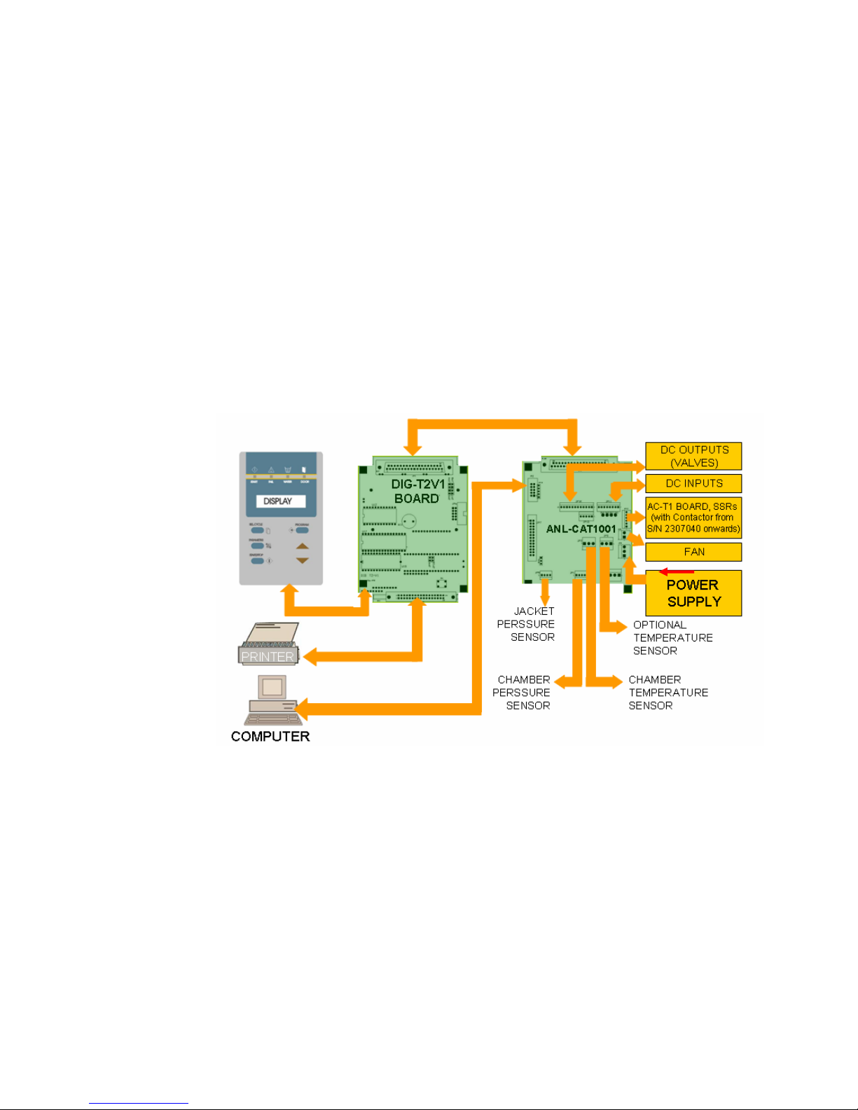
4.1 System Summary
The hardware portion of the control system consists of a keyboard and
3 additional electronic boards designed specifically to match the
requirements of the EHS autoclave. The main board is the digital
board, DIG-T2, which contains the microprocessor and is responsible
for controlling the system. The analog board, ANL-T2, interfaces with
the DIG-T2 board and the various system components processing
signals traveling to and from these areas. The AC-T1 board consists of
AC power filters and drivers for the AC components in the system. DC
power (12V and 5V) for all the DC components is supplied by a
switching type power supply. In addition the system is capable of
direct communication with a printer over a parallel interface and/or a
PC via an RS 232 port (for more detail see individual descriptions
below).
CONTROL SYSTEM BLOCK – DIAGRAM
The following paragraph applies only to the 3870EHS
From S/N 2307040, a Varistor is connected, in parallel, to each of the
SSR’s contacts, in order to decrease the voltage spikes, caused by the
operation of the power devices (pumps and heating elements).
In the 3 phase system (in our case, the 3870EHS) the current, to the
heating elements, is supplied via a contactor. A “CUT OFF” thermostat
is connected to the contactor's coil. If the temperature of the heating
elements exceeds the alarm value, the “CUT OFF” thermostat
disconnects the contactor coil, the contactor's contacts open ("off"
position) and the heating elements are disconnected from the electrical
power.
Page 14

13
4.2 Keyboard
The keyboard is mounted to and directly connected to the DIG-T2
board and functions as an MMI (Man-Machine Interface). The keypad
serves as a control panel containing the command and programming
keys. It also includes an LCD display with two rows of 16 characters
for cycle progress updates and error messages. In addition it contains
the following light indicators:
— START (autoclave in process),
— FAIL (the process failed),
— WATER (no water in the reservoir),
— DOOR (blinks with buzzer sound when START is
pressed and the door is not closed).
For more detail on the control keys and error messages please see the
EHS Operators Manual
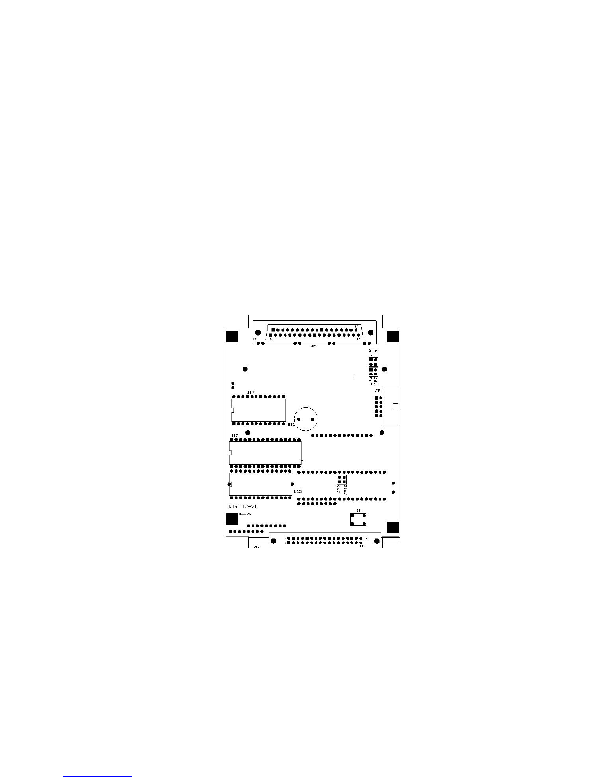
4.3 Digital Board DIG - T2
The digital board contains the microprocessor that runs the system
software program and controls all the functions of the EHS autoclave.
It is connected to the Keypad and digital display for interactive
communication with the operator. It is also connected to the ANL-T2
analog board for communication with the rest of the EHS autoclave. In
addition the DIG-T2 board has PC and printer communication abilities.
— The digital board is connected to the keypad and the ANL-T2
analog board via ribbon cables.
The DIG-T2 board receives human commands through the Keypad
and transmits visual information back, through the Keypad display
The DIG-T2 board receives sensory information, from system
sensors, in the form of digital signals through the ANL-T2 board. It
also transmits operational commands, in the form of digital signals,
to the various system components through the ANL-T2 board.
Power for the DIG-T2 is provided by the ribbon cable connected to
the ANL-T2
— The digital board also contains a parallel printer port for connection
to a proprietary printer. The printer is connected directly to this
board through connector DS1 via a ribbon cable. The printer
receives data and operating voltage directly from this connector.
— The PC interface establishes two-way communication between the
DIG-T2 board and a stand-alone personal computer, utilizing
proprietary software. This communication is via a connector
located on the ANL-T2 board and ribbon cable leading to an
external connector on the front panel.
— On the board, are three types of memories:
1) EPROM memory (U15) for storing the program codes.
2) RAM memory (U9) with a capacity of 64KB for the storage of
temporary data during the running of the program that is
located on the opposite side. This information is only for
general knowledge.
Page 15
14
3) FLASH memory (U17) serves as a non-volatile memory,
enabling the system to change follow-up tables during running
of program codes, and ensuring this data is not lost in case of
power failure.
— The board contains a Real Time Clock element (U12), which
serves as a clock to the system. It includes a back-up battery, which
ensures that the clock runs continuously even when the autoclave is
not powered.
— The back-up battery RAM includes a 113-byte memory component
for storing the parameters currently in use.
— The board contains a solid-state component (U18) that acts as a
system watchdog. This component detects any faulty situation
while the program code is running. It forces the micro-controller to
recheck system inputs every 1.5 seconds, this prevents the software
from becoming stuck in a program loop, that would lead to the
software crashing and a loss of control of the machine.
The layout of the DIG-T2 board components is provided below
DIG- T2 BOARD
— The system provides two types of communication with PC
software, RS232 and RS485. Jumpers on the DIG-T2 board need
to be set differently for each type. The default is RS232 (see also
ANL-T2 board):
1. RS232 – JP4, JP5, JP9 are closed. RS232 allows a single
communications port on the computer to communicate with a
single EHS autoclave.
2. RS485 – JP7, JP8, JP10 are closed. RS485 allows a single
communications
port, with RS485 capability, to
communicate with multiple EHS autoclaves daisy chained
together.
— The system is equipped with a hardware-reset switch (S1).
Page 16

15
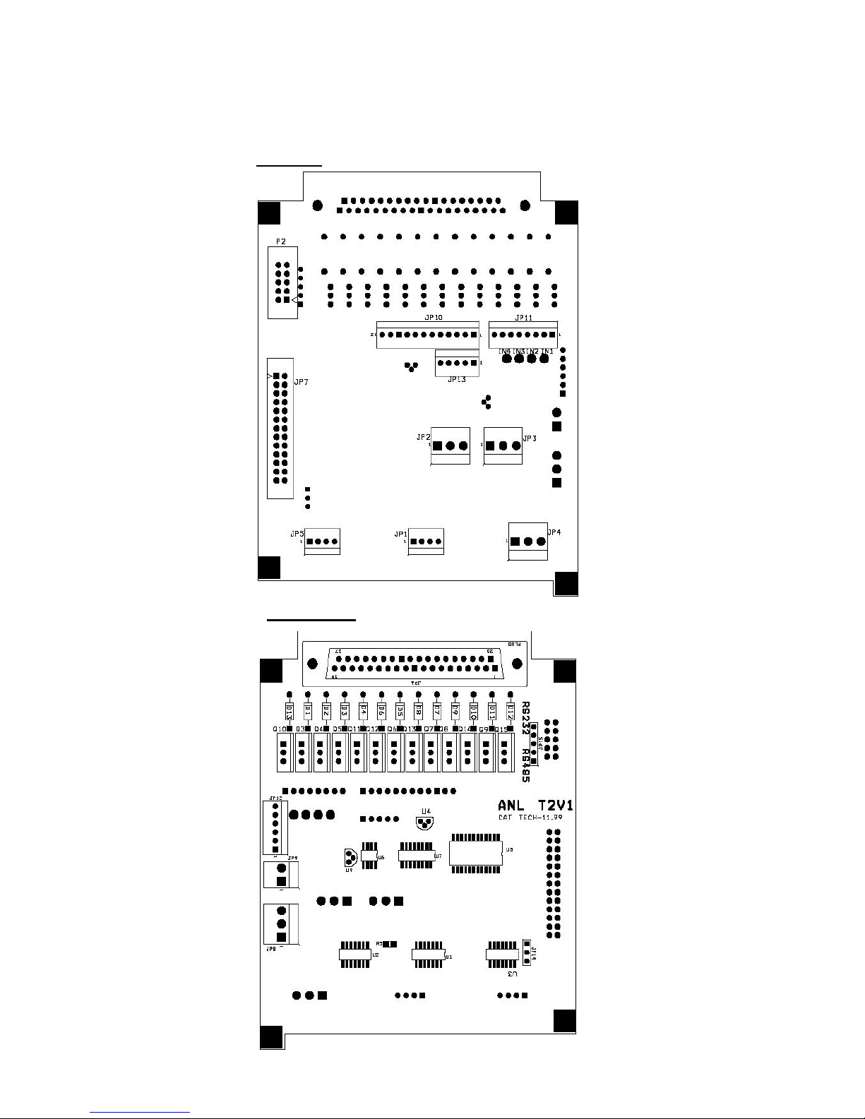
4.4 Analog Board ANL-T2
The analog board contains the DC power transistors that drive the
valves, heaters and pumps. It contains the sensor circuits that decode
the information from the temperature and pressure sensors before
passing that information on to the DIG-T2 board. All the systems
electronic components are connected through the ANL-T2 board. The
analog board is connected to the AC-T1 board that controls the AC
voltage devices. The power supply supplies 12 VDC and 5 VDC to the
analog board and the ANL-T2 distributes that power to the remaining
electronic components.
— JP1 & JP5 are connected to the two MPX2200 pressure sensors that
measure the chamber & jacket pressure.
— JP2 receives the digital input from the PT-100 temperature sensor
— JP8 is connected to the Power Supply and receives the 12VDC and
the 5VDC.
— JP6 provides a connection to the DIG-T2 board
— JP7 provides a connection for the Test Point board needed in
troubleshooting.
— JP9 provides control for the cooling fan
— JP10 connects the DC output drivers to the solenoid valves.
— JP11 is connected to the various digital inputs, such as the water
electrodes, door switch, float switches, etc.
— JP12 is directly connected to the SSR controlling the heaters. It
also provides a digital connection to the AC_T1F board, which
controls the water and vacuum pumps and the steam valve.
— JP13 is not applicable in the EHS Machine.
— JP14 is not applicable in the EHS Machine.
— JP15 is used to match the communication connector configuration
to either RS232 or RS485. The default is RS232 (see also DIG-T2
board):
1. RS232 – JP15, short pins 2 & 3, 4 & 5.
2. RS485 – JP15, short pins 1 & 2, 3 & 4.
— P2 provides a link to the serial port on the front of the unit, via a
ribbon cable.
Page 17
16
Layout diagram of the ANL-T2 is provided below.
ANL- T2 BOARD
Top View
Bottom View
Page 18

17
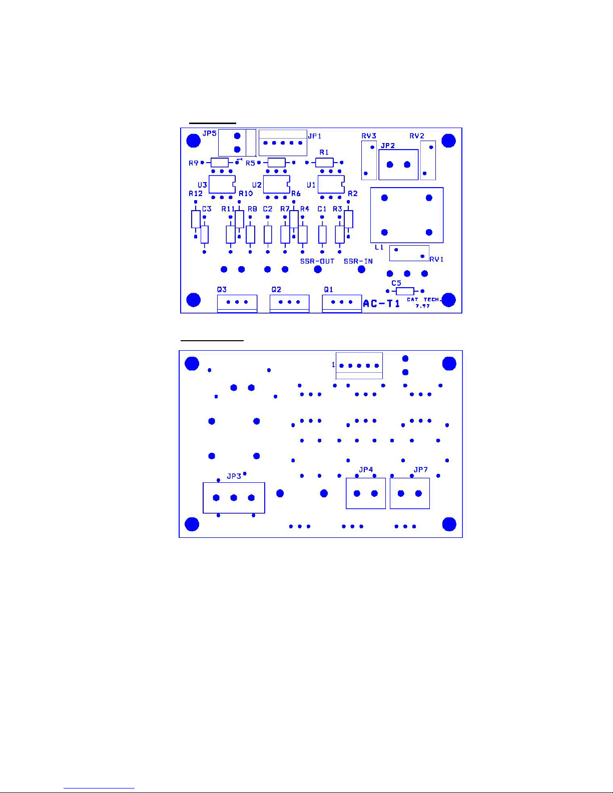
4.5 AC - Board - AC-T1
The AC-T1 board provides AC filtering to protect the power supply
and the control system from voltage spikes. This board contains the AC
voltage drivers that control the AC devices in the system. This is done
by accepting command signals indirectly from the DIG-T2 board
through the ANL-T2 analog board and then turning the devices on or
off.
The AC-T1 board includes:
— A filter circuit utilizing the L1C5 isolation transformer.
— JP2 provides filtered power to the power supply.
— Three 230/115 VAC triac control circuits. These are the AC
drivers used in controlling the water and vacuum pumps and the
steam valve.
— The maximum amperage this board is capable of controlling is 6A.
— Spike protection is provided by three components, RV1, RV2 and
RV3. These components provide a resistibility proportional to the
spike level. The resistibility decreases when the spike level
increases, so that the current will be transferred to the ground
instead of damaging the autoclave’s system.
— JP1 is the control signal input from the ANL-T2 board
— JP3 is the AC input connector.
— JP4 is the output to the steam valve if an AC valve is used
— JP7 is the output to the water and vacuum pumps
Page 19
18
AC-T1 BOARD
Top View
Bottom View
Page 20

19
5 CALIBRATION OF PRESSURE AND TEMPERATURE
5.1 Calibration Overview
The calibration of temperature and pressure is performed digitally. This
system does not have adjustment pots. All calibrations are preformed
through the keypad. The calibration procedure is identical on all EHS
models.
The electronic temperature and pressure measuring circuits built into
the EHS are designed with components having 1% accuracy.
The pressure circuit produces a linear output and has an electrical
output range of 100mv - 2400mv, which corresponds to a pressure
range of 0 - 58 psia.
The temperature circuit also produces a linear output and has an
electrical output range of 100mv - 2400mv, which corresponds to a
temperature range of 68°F (20°C) - 302°F (150°C).
The temperature and pressure circuits provide analog input voltages
that are converted to digital signals by the A/D converter. The
performance of the Analog to Digital converter (A/D) is limited for
values greater than 2400mv or less than 100mv.
The system has a non-volatile memory in which the offset and gain
data of the sensors are stored, as well as any error compensation factors
that are calculated. Storage in the no-volatile memory means that even
if the main power is turned off the information is saved for use the next
time the machine is run.
Calibration is performed by entering data through the keypad or a
stand-alone computer when the PC communication port is used.
Page 21

20
5.2 Calibration Theory - Error Compensation:
The system’s error compensation is based on a calculation involving
two points. These points represent the low and high end of the
autoclaves operating temperature or pressure range.
Each point has two values; one value is the “A” actual (measured)
reading of either temperature or pressure (from a PT simulator,
independent thermometer or pressure gauge). The other value is the
“R” the reading from the autoclave’s digital display of either
temperature or pressure. By entering these values into the unit through
the keypad the system is able to calculate a compensation factor that
will correct the digital display and allow it to accurately return the
actual temperature or pressure.
Note: The two points that are selected will define the range of the error
compensation. Although points above and below are not part of
the compensation, the calibration produces a linear compensation
and these values will be accurate.
Note: The temperature can be calibrated in either °F or °C, depending
on what units the machine is set to display.
Note: The pressure calculations are always done in Absolute pressure
(Absolute pressure = atmospheric pressure + 14.5)
The calibration steps that follow will allow you to automatically
correct the displayed temperature and pressure so it accurately reflects
the actual temperature and pressure. All you need do is input the
appropriate data (actual and displayed values) into the system through
the keypad and the on board computer will do the rest.
Note: It is necessary to know the actual and displayed values prior to
entering the calibration mode.
5.3 Equipment needed for calibration
— A PT100 simulator
— Saturated Steam Table (para 7)
5.4 Calibration Procedure
Calibration consists of three (3) parts and needs to be preformed in the
following order. It is not advisable to perform only a partial calibration
1. Check that the atmospheric pressure parameter is set correctly (see
sec 8.2.17)
2. Collect and enter temperature data
3. Collect and enter pressure data
5.4.1 Connecting the test equipment
Remove the outer cabinet
Disconnect the PT100 temperature sensor from the JP2
connector on the ANL_T2 board
Connect the PT100 simulator to JP2
Page 22

21
5.4.2 Collecting and entering temperature data
When collecting data, keep in mind that “A” is always the
actual temperature and “R” is always what is being displayed
on the digital screen of the autoclave.
Once in the calibration mode, the calibration screen will look
similar to this:
Upper Row: A 140.0 R 140.0 (lower temp reading °F)
Lower Row: A 266.0 R 266.0 (higher temp reading °F)
When entering data, remember that the upper row will
represent the lower temperature of the chamber and the bottom
row will represent the higher temperature of the chamber.
5.4.2.1 Collecting temperature data
— Select the low setting on the PT100 simulator
(it is suggested to use 158°F)
This will be the “A” value for the upper row.
— Record the temperature displayed on the screen
(there can be a slight delay in updating the screen
when changing values on the PT100 simulator)
This will be the “R” value for the upper row.
— Repeat this procedure for the high setting using
the PT100 simulator (it is suggested to use
266°F)
These values will be for the bottom row
— Once the data is collected disconnect the PT100
simulator from JP2 and reconnect the PT100.
5.4.2.2 Entering temperature data
Access the calibration mode as described in para
5.4.4.
— The cursor will appear flashing under the value
for “A” in the upper row.
— Using the UP/DN arrow keys, enter the value
for “A”. This will be the first temperature value
that the PT100 simulator was set for.
— Press the PROGRAM key to advance to the
next value.
— The cursor on the upper row will move one
position to “R”; now enter the first temperature
value recorded from the display
— Press the PROGRAM key to advance to the
next value that will be in the bottom row.
— The cursor will be positioned under the value
for “A” in the bottom row.
Page 23

22
— Enter the value for “A”. This will be the second
temperature value that the PT100 simulator was
set for.
— Press the PROGRAM key to advance to the
next value.
— The cursor on the bottom row will move one
position to “R”. Now enter the second
temperature value recorded from the display
— Press the PROGRAM key one final time.
If PROGRAM WAIT has not been displayed
then continue to press the PROGRAM key until
it appears.
After a brief period the unit will return to a
Ready state
5.4.3 Collecting and entering pressure data
When collecting data, keep in mind that “A” is always the
actual pressure and “R” is always what is being displayed on
the digital screen of the autoclave. Under normal
circumstances calibration only needs to be done at the high
end of the pressure range.
Once in the calibration mode, the calibration screen will look
similar to this:
Upper Row: A 15 R 15 (atmospheric pressure reading)
Lower Row: A 45 R 45 (high pressure reading)
When entering data, remember that the upper row represents
atmospheric pressure and the bottom row represents the high
pressure of the chamber. And that all entrees are in absolute
pressure.
“If the display reads a chamber pressure of 00, with the door
of the autoclave open, then proceed directly to 5.4.3.2.
If the reading is not 00 then proceed as follows.
5.4.3.1 Atmospheric pressure calibration
Set the Atmospheric pressure parameter (see 8.2.17)
— If the read out on the display is at least 1psi
above or 1Ih below 00 then access the
calibration mode as described in para 5.4.4
The cursor will appear flashing under the value
for “A” in the upper row.
— Press the Program key to advance to the next
value “R” in the upper row
Page 24

23
— Using the UP/DN arrow keys raise the value of
“R” if the display reads high. Lower the value
of “R” if the display reads low.
(Example: if the display reads 2 psi, then raise
the value of “R” by 2; if it reads 2Ih then lower
the value of “R” by 2)
— Press the program key until PROGRAM WAIT
is displayed. The autoclave will recalibrate and
return to the Ready state.
— If the display now reads 00, with the door of the
autoclave open, then continue on to sec 5.4.3.2”
5.4.3.2 Collecting pressure data
— Select a program with a sterilization
temperature of 273 °F (134 °C), make sure the
door is closed securely and press START.
— Let the unit cycle to maximum pressure that will
be reached once the unit has entered the
sterilization mode.
— Record the temperature and pressure from the
digital display.
— Abort the cycle by pressing the STOP key.
— Consult the Saturated Steam Table for the
Absolute pressure that corresponds to the
temperature recorded in the previous step and
record that value.
— Add 14.5 to the pressure reading from the
digital display and record this value
5.4.3.3 Entering pressure data
Access the calibration mode as described in para
5.4.4.
— The cursor will appear flashing under the value
for “A” in the upper row.
— Press the PROGRAM key to advance to the next
value.
— The
cursor on the upper row will move one
position to “R”.
— Press the PROGRAM key to advance to the next
value that will be in the bottom row.
— The cursor will be positioned under the value for
“A” in the bottom row.
— Enter the value for “A”. This will be the value
of absolute pressure recorded from the Saturated
Steam Table
Page 25

24
— Press the PROGRAM key to advance to the next
value.
— The cursor on the bottom row will move one
position to “R”; now enter the pressure value
recorded from the digital display to which you
have already added 14.5.
— Press the PROGRAM key one final time
If PROGRAM WAIT has not been displayed then
continue to press the PROGRAM key until it appears.
After a brief period the unit will return to a Ready
state
This completes the calibration procedure for
temperature e and pressure. A sterilization cycle
should be performed to verify that the system is
calibrated and running properly.
Page 26

25
5.4.4 Accessing the calibration mode
— With the unit turned on press the PROGRAM key.
— Pressing the PROGRAM key will bring you to its
first function of setting the system’s date the time.
— Setting the date and time can be bypassed by pressing the
PROGRAM key six times.
— On the seventh press of the PROGRAM key CODE:
∅∅∅ will be displayed.
— Advance the code to 011 by pressing the UP arrow key
(this is a technician level code) then press the
PROGRAM key.
— Continue pressing the program key until CALIB CODE:
1∅∅ is displayed.
— Using the UP arrow key select CALIB CODE: 107.
— Press the PROGRAM key again until Program Wait is
displayed, this is an intermediate calibration phase. Once
the program wait is completed TEMP CAL: ∅∅∅ will
be displayed.
— Using the UP arrow key advance to TEMP CAL: ∅∅1
— Press the PROGRAM key again. This is the Temperature
Calibration mode and the data is ready to be entered
— Press the PROGRAM key one additional time and the
display will show PRESS CAL: ∅∅∅.
— Using the UP arrow key advance to PRESS CAL: ∅∅1
— Press the PROGRAM key again. This is the Pressure
Calibration mode and the data is ready to be entered
Page 27

26
6 TESTING AND RESETTING
6.1 Test Points
These test points are provided to assist in trouble shooting the
autoclave. A test point board is needed to be able to read these test
points.
NU TP
FUNCTION
VALVE
TP1
GND
TP2
+5V DC
TP3
+12V DC
TP4
OUTPUT HEATERS 0V-Off; 5V-On
TP5
OUTPUT VACUUM PUMP 0V-Off; 5V-On
TP6
TP7
OUTPUT AIR INLET VALVE (43) 0V –CLOSE; 5V-OPEN
TP8
OUTPUT VACUUM VALVE (52) 0V –CLOSE; 5V-OPEN
TP9
OUTPUT
MINERAL FREE WATER TO
RESERVOIR (21)
0V-Off; 5V-On
TP10
OUTPUT WATER TO VAC PUMP (15) 0V-Off; 5V-On
TP11
TP12
OUTPUT STEAM TO CHAMBER (93) 0V –CLOSE; 5V-OPEN
TP13
OUTPUT SLOW EXHAUST (74) 0V –CLOSE; 5V-OPEN
TP14
OUTPUT DRAIN COOLING WATER (13) 0V-Off; 5V-On
TP15
OUTPUT WATER TO VAC PUMP RES. (14) 0V-Off; 5V-On
TP16
OUTPUT FAST EXHAUST (73) 0V –CLOSE; 5V-OPEN
TP17
OUTPUT WATER PUMP 0V-Off; 5V-On
TP18
TP19
TP20
TP21
INPUT TEMPERATURE-1 (PT100) 273ºF = 1.97V
TP22
INPUT JACKET PRESSURE 29.4 psi = 2.031V
TP23
TP24
INPUT CHAMBER PRESSURE 29.4 psi = 2.031V
0V = SATISFIED
TP25
INPUT LOW WATER ELECTRODE
2.5V = NOT SATISFIED
0V = SATISFIED
TP26
INPUT HIGH WATER ELECTRODE
2.5V = NOT SATISFIED
Page 28
27
6.2 In – Out Test mode:
To enter the test mode –
• Turn off the main power switch
• While pressing and holding the UP arrow key, turn on the main
power switch.
The output test starts immediately
Each output (valves, heaters, pumps), will be activated and the name of
that device will be displayed.
To switch from one output to another, press the UP arrow key.
When all the outputs have been tested the input tests will begin again.
To leave the In – Out test mode, turn off the main power switch.
DISPLAYED
NOTICE
ITEM ACTIVATED REMARKS
Heaters ON Heating Elements Heating elements are activated.
Pump On Vacuum pump
Pump is operating only if there
is water in the vacuum pump
reservoir
Water ON Water pump for jacket ULKA water PUMP operates.
Air On Air valve (43) Air valve is open.
Water Res On
Mineral free water reservoir
valve (21)
Water valve to mineral free
reservoir is open.
Exh Res On Vacuum exhaust valve (52) Vacuum exhaust valve is open.
Steam On Steam valve (93)
Steam valve from jacket to
chamber is open.
Vacum Wtr On Water valve (15)
Water valve from reservoir to
vacuum pump is open.
Door Lock ON Door locking solenoid
Door locking solenoid is
activated (retracted). (only on
units with an electric door
lock)
Slow Ex On Slow Exhaust valve (74) Slow exhaust valve is open.
Exh Drain On Fast Exhaust valve (73)
Fast Exhaust valve from
chamber to drain is open
Cool wtr On Cooling water valve (13)
Exhaust Cooling water valve is
open
Electrd –h 0
Electrode senses water in the
jacket
Electrd –h 255
High water level electrode
Electrode does not sense water
in the jacket and activates the
water pump
)continued on next page(
Page 29
28
DISPLAYED
NOTICE
ITEM ACTIVATED REMARKS
Electrd –l 0
Electrode senses water above
minimum level in the jacket
Electrd –l 255
Low water level electrode
Electrode does sense water
above minimum level in the
jacket and disconnects heating
elements
Door Sw “0” Door switch activated
Door Sw “1”
Door switch
Door switch not activated
Float -l “0” Float switch senses water
Float -l “1”
Lower mineral free float
switch. (move the float
switch and verify that it
operates)
Float switch does not sense
water and stops operation of
water pump
Float –H “0”
Float switch senses water and
closes valve 21
Float –H “1”
Upper mineral free float
switch. (move the float
switch and verify that it
operates)
Float switch does not sense
water and opens valve 21
6.3 Resetting the Autoclave:
Whenever it becomes necessary to restore the system to normal
operation, the system must be reset. This will remove corrupted data
from memory and restore a healthy program. On occasion other
situations require that a reset be preformed, they are as follows:
— When the machine is operated for the first time
— If the machine has been sitting unused for a long period of time.
— When the cycle has not been completed, as a result of a power
failure or manual stop
To reset the system; proceed as follows:
Turn power off using the green power button at the bottom of the front
panel, press and hold the Sel. Cycle button on the keypad, turn power
on, continue to hold the Sel. Cycle button until program wait appears
on the screen then release.
After resetting, the autoclave will be in the stand-by
mode
Page 30
29
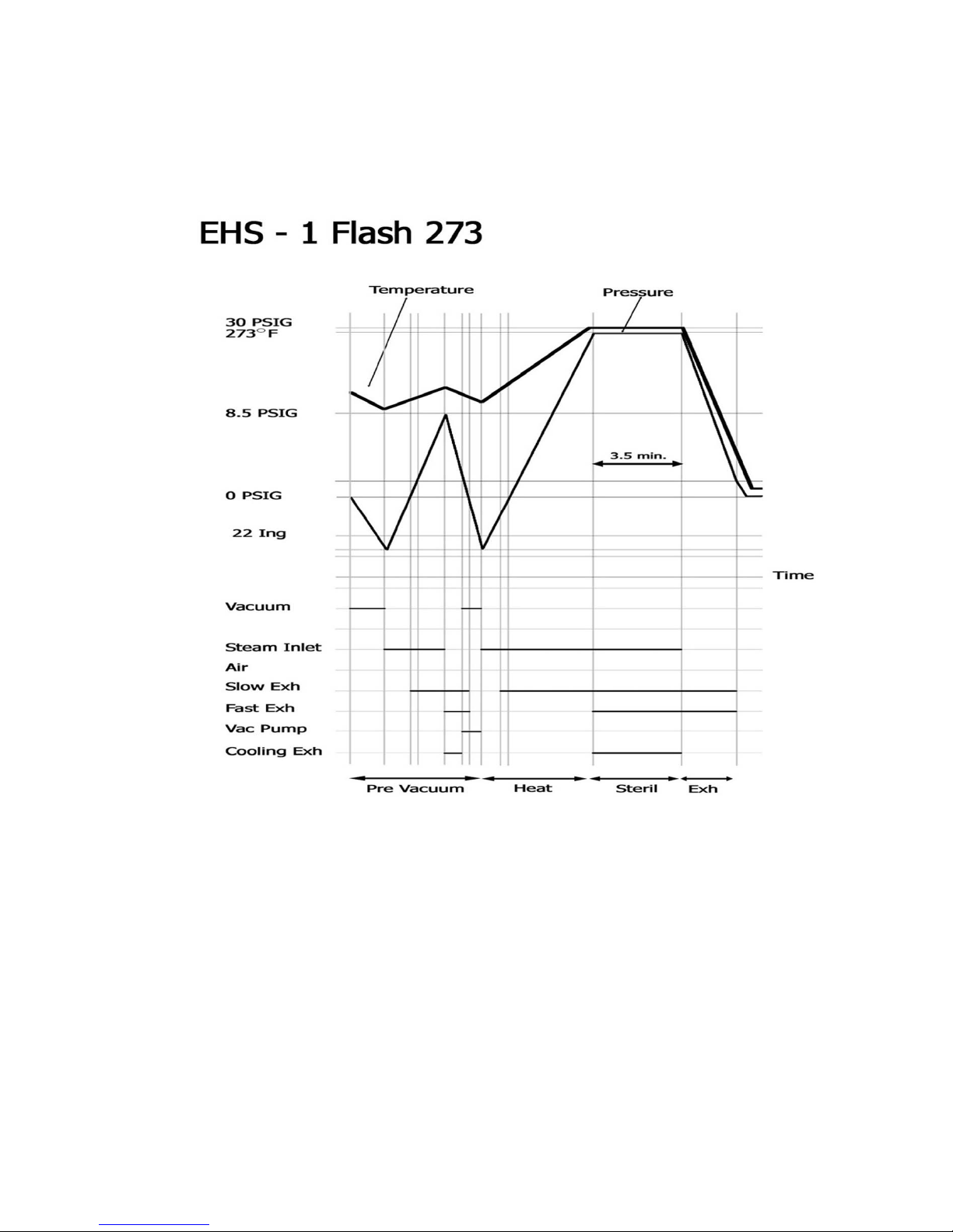
6.4 Input Output Graph:
Page 31

30
Page 32

31
Page 33

32
Page 34

33
Page 35

34
Page 36

35
7 PROPERTIES OF SATURATED STEAM
(From Baumiester & Marks “Standard Handbook for Mechanical Engineers”
7th Edition)
Gauge
Pressure
Absolute
Pressure
Temp °F
Gauge
Pressure
Absolute
Pressure
Temp °F
0
14.7
212.00 31
45
274.44
1
15
213.03 32
46
275.80
2
16
216.32 33
47
277.13
3
17
217.44 34
48
278.45
4
18
222.41 35
49
279.74
5
19
225.24 36
50
281.01
6
20
227.96 37
51
282.26
7
21
230.57 38
52
283.49
8
22
233.07 39
53
284.70
9
23
235.49 40
54
285.90
10
24
237.82 41
55
287.07
11
25
240.07 42
56
288.23
12
26
242.25 43
57
289.37
13
27
244.36 44
58
290.50
14
28
246.41 45
59
291.61
15
29
248.40 46
60
292.71
16
30
250.33 47
61
293.79
17
31
252.22 48
62
294.85
18
32
254.05 49
63
295.90
19
33
255.84 50
64
296.94
20
34
257.08 51 65 297.97
21
35
259.28 52
66
298.99
22
36
260.95 53
67
299.99
23
37
262.57 54
68
300.98
24
38
264.16 55
69
301.96
25
39
265.72 56
70
302.92
26
40
267.25 57
71
303.88
27
41
268.74 58
72
304.83
28
42
270.21 59
73
305.76
29
43
271.64 60
74
306.68
30
44
273.05
Page 37

36
8 SOFTWARE PROGRAMMING PARAMETERS
8.1 General
The software version that runs the control system of the EHS autoclave
can be found by turning the unit on and watching the display. The
version number is also printed if a printer is installed.
The software contains a table of parameters of which some of them
define the autoclave, and some of them define the processes in the
autoclave. This section of the manual describes the parameters and how
they control the software.
8.2 Changing Parameters
An access code is needed to change any parameters other than the date
and time.
Two access codes are currently available and each one gives a different
level of access.
Access code 1 – This is the first level of access. This code enables
changing of the sterilization time, sterilization
temperature and the drying time. This level of access
is suitable for a senior office person in the medical
facility.
Access code 13 – This is the second level of access. This code is for the
technician and allows access to make changes such as
calibrations.
To change the parameters listed below, proceed as follows:
a. Select the program cycle, to be modified, by pressing the
SEL.CYCLE key.
b. Press the PROGRAM key until CODE: ∅∅∅ appears
c. Using the UP/DN keys enter the access code for the level of access
desired. (i.e. CODE:013)
d. Select the parameter to be modified, by pressing the PROGRAM
key until the parameter name appears on the display.
e. Set the desired data by means of the UP/DN keys.
f. Pressing the PROGRAM key will enter the modified data into
memory, and move to the next parameter.
g. When finished press the PROGRAM key until the message
PROGRAM WAIT appears. The software is reprogramming itself
with the modifications that were made.
Note: Each of the 6 program cycles has a set of the following
parameters. Changing a specific parameter in one program will
not change it any other program.
Listed below are all the available parameters for the EHS. Each section
describes the parameter, shows the access code required to be able to
make modifications, it shows the minimum and maximum allowed
values and the increments (resolution) by which these values can be
changed. Also included are the pre-set values of the parameters for
each cycle.
Note: If a parameter is modified the only way to return to the original value is
to manually reenter it.
Page 38

37
8.2.1 SteTemp – Temperature required for sterilization
This parameter will set the desired temperature for sterilization
Access Code - 1
Resolution - 1ºF
Minimum value - 250ºF
Maximum value - 280ºF
Cycle
1 2 3 4 5 6
Default
Values
Value
273 273 250 273 273 -
8.2.2 Ster Time – Time required for sterilization
This parameter will set the time desired for sterilization
Access code - 1
Resolution - 1 minute
Minimum value - 3 minute
Maximum value - 59 minutes
Cycle
1 2 3 4 5 6
2540
3.5 8 30 4 3.5 -
Default
Values
Value
3870
3.5 8 30 8 3.5 -
8.2.3 Dry Time – Time required for drying
This parameter will set the time desired for drying
Access Code - 1
Resolution - 1 minute
Minimum Value - Ø minutes
Maximum Value - 59 minutes
Cycle
1 2 3 4 5 6
Default
Values
Value
0 20 20 20 2 -
8.2.4 HeatT.O. – Sterilization temperature time out
This parameter will set the maximum time allowed, from the
beginning of the cycle, for the chamber to reach sterilization
temperature. When the HeatT.O is exceeded, the program aborts
with the message ‘Low Heat’.
Access Code - 13
Resolution - 30 seconds
Minimum Value - 1200 seconds
Maximum Value - 3180 seconds
Cycle
1 2 3 4 5 6
Default
Values
Value
3000 3000 3000 3000 3000 0
Page 39

38
8.2.5 Ex.Mode – Rate of steam discharge during the exhaust stage
This parameter sets the rate at which steam is discharged during
the exhaust stage.
Access Code - 13
Resolution - 1
Value - 1 or 4
Fast Exhaust = 1
Slow Exhaust = 4
Cycle
1 2 3 4 5 6
Default
Values
Value
1 1 1 1 1 1
8.2.6 End Temp – Cycle End Temperature
This parameter sets the finish temperature of the exhaust stage.
The unit will signal a Cycle End only when the exhaust timer
has reached zero and the unit is below the End Temp. This also
indicates the proper time to open the door and unload the
chamber.
Access Code - 13
Resolution - 1ºF
Minimum Value - 104ºF
Maximum value - 280ºF
Cycle
1 2 3 4 5 6
Default
Values
Value
273 273 250 273 273 280
8.2.7 Puls num
.–
No. of vacuum pulses in the prevacuum stage
This parameter sets the number of vacuum pulses during the
prevacuum stage.
Access Code - 13
Resolution - 1
Minimum Value - 1
Maximum Value - 7
Cycle
1 2 3 4 5 6
Default
Value
Value
2 4 4 4 4 1
Page 40

39
8.2.8 Vac dip1
–
Vacuum value of the first vacuum pulse
This parameter sets the value of the vacuum that pulse no.1
needs to achieve in the prevacuum stage. This parameter is
expressed in psia (atmospheric pressure at sea level is =
14.7psia). A psia lower than 14.7 indicates a vacuum. (During a
cycle the autoclave displays vacuum as Ih (inches of mercury).
29.93 Ih = 14.7 psia (atmospheric pressure at sea level))
Access Code - 13
Resolution - .1 psi
Minimum Value - 1 psia
Maximum Value - 13 psia
Cycle
1 2 3 4 5 6
Default
Value
Value
2.9 3.7 3.7 3.7 2.9 2.7
8.2.9 Vac dip2
–
Vacuum value of each of the remaining pulses
This parameter sets the value of the vacuum that the remaining
pulses (starting from pulse no. 2) need to achieve in the
prevacuum stage. This parameter is expressed in psia
(atmospheric pressure at sea level is = 14.7psia). A psia lower
than 14.7 indicates a vacuum. (During a cycle the autoclave
displays vacuum as Ih (inches of mercury). 29.93 Ih = 14.7 psia
(atmospheric pressure at sea level))
Access Code - 13
Resolution - 0.1 psi
Minimum Value - 1 psia
Maximum Value - 13 psia
Cycle
1 2 3 4 5 6
Default
Values
Value
2.9 3.7 3.7 3.7 2.9 2.7
8.2.10 VacTime1
–
Waiting time at the end of the first pulse
This parameter sets the wait time at the end of the first vacuum
pulse, during the prevacuum stage. After reaching VacDip1,
there is a waiting time to allow the unit to stabilize. This time is
defined as VacTime1 and during this time the vacuum system
continues working.
Access Code - 13
Resolution - 1 second
Minimum Value - 3 seconds
Maximum Value - 1800 seconds (30 minutes)
Cycle
1 2 3 4 5 6
Default
Values
Value
3 3 3 3 3 3
Page 41

40
8.2.11 VacTime2
–
Waiting time at the end of each of the remaining
pulses
This parameter sets the wait time at the end of each of the
remaining vacuum pulses, during the prevacuum stage. After
reaching VacDip2, there is a waiting time to allow the unit to
stabilize. This time is defined as VacTime2 and during this time
the vacuum system continues working.
Access Code - 13
Resolution - 1 second
Minimum Value - 3 seconds
Maximum Value - 1800 seconds (30 minutes)
Cycle
1 2 3 4 5 6
Default
Values
Value
3 3 3 3 3 3
8.2.12 WtrResTime – Timed extension for pumping mineral free
water
This parameter sets the length of time to continue pumping
mineral free water into the steam generator after the upper
electrode senses water.
This is necessary to prevent a situation where the water pump
would cycle on and off as the water level rises and falls around
the upper water-sensing electrode.
Access Code - 13
Resolution - 1 minute
Minimum Value - Ø minutes
Maximum Value - 90 minutes
Cycle
1 2 3 4 5 6
Default
Values
Value
5 5 5 5 5 5
Page 42

41
8.2.13 limitP add
–
defines the upper limit of the pressure in the
jacket
This parameter is designed as a safety measure that defines the
maximum pressure in the jacket during heating and sterilization
stages. The maximum working pressure in he jacket is defined
as the pressure that correlates to the sterilization temperature
+ 5.4°F. Parameter limitP add allows to increase the pressure
above the maximum working pressure and defines the value of
this pressure.
Caution:
Setting this parameter to 4 psi may cause the Pressure Switch
and / or the Safety Valve to be activated.”
Example:
If the sterilization temperature is 273°F, the maximum pressure
will be 34 psig that correlates to 278.4°F (273°F + 5.4°F). If
limitP add is 2 the maximum allowable pressure will be 36. If
the pressure reaches the upper limit as defined by limitP add
(i.e. 36 in our example) the heating element will be switched off
and the pressure will begin to decrease. When the pressure
decreases below the maximum allowable pressure, the heating
element will be switched on again.
Access Code - 13
Resolution - 0.1 psi
Minimum Value - Ø psi
Maximum Value - 4 psi
Cycle
1 2 3 4 5 6
Default
Values
Value
0 0 0 0 0 0
8.2.14 Calib Code – Calibration Code 107
This parameter is used to set the calibration code. The correct
code is needed to calibrate the autoclave. After calibration the
code should be set back to the default value (100) to prevent any
unqualified person from altering the calibration
Access Code - 13
Resolution - 1
Minimum Value - 0
Maximum Value - 255
Cycle
1 2 3 4 5 6
Default
Values
Value
100 100 100 100 100 100
Page 43

42
8.2.15 ReqPrs+ - Overrides the pressure calculated for sterilization
This parameter is used to insure that during sterilization the
temperature is correctly maintained. It does this by raising the
value of the sterilization pressure necessary to maintain a
sterilization temperature. The sterilization pressure is calculated
by the unit based upon the SteTemp parameter.
For example; if the required temperature is 250ºF, the required
pressure calculated by the program is 16 psig.
This pressure can be increased by changing the value of
ReqPrs+. If this value is set to ø, the system will be maintained
at 16 psig during the sterilization stage if this value is set to 1.5,
the system will be maintained at 17.5 psig in the sterilization
stage.
Access Code - 13
Resolution - 0.1 psi
Minimum Value - Ø
Maximum Value - 3 psi
Cycle
1 2 3 4 5 6
Default
Values
Value
0.8 0.8 0.6 0.8 0.8 0
Page 44

43
8.2.16 Dry Vac
–
Pressure during the Dry Stage
This parameter is intended to control the vacuum pressure
during the Drying Stage. It does this by opening and closing the
Air Inlet Valve. In all cases the vacuum pump runs continuously
and the Jacket is heated until the end of the Dry stage, as set by
the Dry time parameter.
This parameter is expressed in kpa, where 1 kpa = 0.145 psia
Access Code - 13
Resolution - 1 kpa
Minimum Value - 0 kpa
Maximum Value - 90 kpa
If Dry Vac = 0, the Air Inlet Valve will be closed during the
Dry Stage.
If Dry Vac is between 1 & 5, the Air Inlet Valve will be
operated in a shoot mode, 30 seconds open and 30 seconds
closed. This process will begin 4 minutes after the start of the
Dry Stage and continue until the Dry stage is completed
If Dry Vac ≥6, the Air Inlet Valve will be used to regulate the
pressure during the Dry Stage so that the value of the pressure
will not fall below the Dry Vac value. E.g., if Dry Vac = 20 (1
kpa = 0.145 psia), then when the pressure reaches 2.9 psia, the
air valve will open and remain open until the pressure rises to
3.6 psia at which point is will close again. When the pressure
drops back to 2.9psia, the valve opens again to allow the
pressure to rise. This process continues until the end of the Dry
stage. In this example the pressure fluctuates between 2.9 psia
and 3.6 psia. The Air Inlet Valve is not working in a shoot
mode, but it opens and closes around the requested Dry Vac
value.
Cycle
1 2 3 4 5 6
Default
Values
Value
5 5 5 5 5 1
Page 45

44
8.2.17 Atmos. Press
–
Atmospheric Pressure
This parameter tells the unit the atmospheric pressure of the
location in which it is installed. The pressure entered must be
with in 5% of the actual atmospheric pressure for that location.
Unlike the other parameters you only need to enter this
parameter once in any one cycle and all cycles will be updated.
This value can easily be calculated by knowing the altitude of
your location. The atmospheric pressure at Sea Level is 14.5
psia. For every 100m above sea level, the atmospheric pressure
drops 0.14 psia, and for every 100m below sea level, the
atmospheric pressure increases 0.14 psia.
Changes in pressure do to weather will not affect the accuracy
of this unit.
Access Code - 13
Resolution - 0.1 psi
Minimum Value - 8 psia (for +4500m)
Maximum Value - 15.7 psia (for –800m)
Cycle
1 2 3 4 5 6
Default
Values
Value
14.5 14.5 14.5 14.5 14.5 14.5
8.2.18 PulsPress – pulse pressure during pre-vacuum stage.
This parameter is used to set the maximum pressure in each
pulse of the pre-vacuum stage. This parameter is expressed in
psia. During St.By (Stand By) and while running a cycle the
display shows pressure in psig. (Psig + 14.5 equals psia).
Access Code – 13
Resolution – 1 psi
Minimum Value – 7 psia
Maximum Value – 30 psia
Cycle
1 2 3 4 5 6
Default
Values
Value
22 23.5 23.5 23.5 23.5 23.5
Page 46

45
8.2.19 Heat Step – sterile temperature overshoot control
This parameter is used to reduce overshoot of the sterilization
temperature by controlling the sterilization pressure. The
sterilization pressure is calculated by the unit based upon the
SteTemp parameter. When the cycle starts the heating rate in
the chamber is constant until the pressure in the chamber
reaches the sterilization pressure minus the Heat Step. From
this point on heating is performed in pulses. Each pulse lasts
15 seconds and increases the pressure in the chamber by a
small amount until the proper sterilization pressure is reached.
Access Code – 13
Resolution – 0.1 psi
Minimum Value – 0.1 psi
Maximum Value – 2 psi
Cycle
1 2 3 4 5 6
Default
Values
Value
0.7 0.7 0.7 0.7 0.7 0.4
8.2.20 PresInPsig – selects the pressure display units.
This parameter sets the units of pressure that are printed by the
printer and used on the digital display during St.By (Stand By)
and while running a cycle. The two choices are psia (absolute
pressure) or psig / InHg (gauge pressure and inches of
mercury) Changing this parameter does not effect the units of
calibration used in any other parameter.
Access Code – 13
Resolution – 1
Pressure is displayed in
Psig and vacuum in InHg – 1
Pressure is displayed in psia – 0
Cycle
1 2 3 4 5 6
Default
Values
Value
1 1 1 1 1 1
8.2.21 TempInC – selects the temperature units.
This parameter sets the units of temperature that are used by
the autoclave.
Access Code – 13
Resolution – 1
Temperature is displayed in °C – 1
Temperature is displayed in °F – 0
Cycle
1 2 3 4 5 6
Default
Values
Value
0 0 0 0 0 0
Page 47

46
8.2.22 Flash – Heating over-pressure control
This parameter is designed to regulate over pressure during the
heat up stage. The system constantly monitors the temperature
and pressure and compares both values to the Saturated Steam
Curve. If the pressure is found to exceed the corresponding
temperature by more than 0.7 psi then the fast exhaust valve is
opened for 1 second in an attempt to realign the temperature
and pressure. The system will wait 15 seconds and check
temperature and pressure again. If needed the fast exhaust will
be opened again for 1 second. This process will continue until
the temperature and pressure are correctly aligned.
Access Code – 13
Resolution – 1
Value – 0 or 1
If Flash = 0 This feature is not activated.
If Flash = 1 This feature is activated.
Cycle
1 2 3 4 5 6
Default
Values
Value
1 1 1 1 0 0
8.2.23 Auto. Num – Autoclave Identification number
This parameter is used to set the identification number relative
to other autoclaves in the facility. This number only appears on
the printout of a unit with a printer installed. It enables the
operator to link the printout with a specific autoclave. This
parameter need only be set once, while in any of the 6
programs.
Access Code – 13
Resolution – 1
Minimum Value – 1
Maximum Value – 99
Page 48

47
9 MAINTENANCE AND REPLACEMENT PROCEDURES
9.1 Safety Tests after Repair
ATTENTION!
After every repair or dismantling of the enclosure, it is
recommended that the following tests be performed:
1. Enclosure Current Leakage Test.
The test should be performed using a Megger. Make sure the
autoclave is unplugged. The electrical potential of the testing
instrument should be 500V. The insulation resistance should be at
least 2 MΩ.
The test is successful if there was no leakage.
2. Protective Earth Impedance Test
The test should be performed using an Ohmmeter. Make sure the
autoclave is unplugged from the wall outlet. Next measure the
resistance between the grounding screw on the rear plate (or any
other unpainted metallic part) and the grounding pin of the power
cord plug. The resistance should not exceed 0.3 Ω, a high
resistance would indicate a faulty ground connection.
Page 49

48
9.2 Removing the Autoclave’s Outer Covers
Caution!
Before starting, disconnect the instrument from the power
source and ensure that there is no pressure in the
chamber or jacket.
Allow the autoclave to cool before removing outer covers.
1. Remove the screws holding the rear cover (1).
2. Remove the screws holding the cover to the base (2).
3. Dismantle the air filter from the service opening cover (3).
3.1. Remove the screws holding the filter cover.
3.2 Disconnect the filter from the silicone tube
4. Remove the grounding wires from the cover.
5. Pull the cover upwards.
Note:
The following picture refers to model 2540
3
21
Page 50

49
9.3 Replacing the Safety Valve
The safety valve is installed to protect the Jacket from over
pressurizing should all the electrical controls fail.
Caution!
Before starting, be sure that the electric cord is disconnected and that
there is no pressure in the chamber or jacket.
1. Take off the autoclave cover (see para. 9.2 “Removing the
Autoclave’s Outer Covers”).
2. Remove the water reservoir gasket.
3. Unscrew the safety valve and remove it from the safety valve base.
4. Replace the valve with a new safety valve (install only an original
equipment replacement!). Use a hydraulic sealant to seal the
threads to ensure that the assembly is leak free.
5. Perform one cycle and verify that the valve operates correctly.
Page 51

50
9.4 Replacing the DIG-T2 board
The DIG-T2 board contains the software program and controls all the
functions of the autoclave. See sec 4.3.
Caution!
Make sure that the power cord is disconnected!
Allow the chamber and jacket to cool before removing outer covers.
Refer to the picture below when following this procedure.
1. Take off the autoclave cover (see para. 9.2 “Removing the Outer
Covers of the Autoclave”).
2. On model 3870 disconnect the flat cable from the printer.
3. Disconnect the flat cable from JP1-DIG-T2 to JP1 ANL-T2 (4).
4. Disconnect the flat cable from the PC port to P1-ANL-T2 (6).
5. Disconnect the green grounding cable (5).
6. Remove the screws that connect the plastic panel, housing the
DIG-T2 board, to the autoclave (2).
7. Disconnect the main switch (7).
8. Remove the DIG-T2 and keypad from the plastic panel.
9. Disconnect the DIG-T2 from the keypad.
10. Install a new DIG-T2 to the keypad and reinstall it into the plastic
housing
11. Follow the previous instructions in reverse to reassemble the unit
9.5 Replacing the Electronics Box
Caution!
Make sure that the power cord is disconnected!
Allow the chamber and jacket to cool before removing outer covers.
Refer to the picture below when following this procedure.
1. Take off the autoclave cover (see para. 9.2 “Removing the Outer
Covers of the Autoclave”).
2. Remove the screws from the bottom and top of the electronic box
(1, 3).
3. Disconnect all the electric system connectors connecting the
electronic box to the base (including the MPX connectors).
4. Remove electronics box and replace with new one.
5. Re-assemble the instrument. Verify that the grounding connections
are connected correctly.
6. Test any cycle and verify that the autoclave operates as required.
Page 52

51
Electronic box: 3870
Electronic box: 2540
Control panel
7 2
63 2
4
5
7
1 1
Electronic
box
Electronic
box
1 17
2
5
6
4
2 3
Control panel
2
7
Page 53

52
9.5 Drain Valve Repair
There are two drain valves on the front of the autoclave. One drains the
mineral free water from the front section of the reservoir and the other
drains the vacuum pump water from the back section of the reservoir.
Caution!
Before starting, disconnect the instrument from the power source and
ensure that there is no pressure in the chamber or jacket.
Allow the autoclave to cool before removing outer covers.
9.5.1 Replacing the O rings
1. Open the manual drain cock on the front of the machine
and drain any water left in the reservoir
2. Continue turning the drain cock in a counterclockwise
direction. Some resistance will be felt, but eventually the
drain cock assembly will come out.
3. Replace the two O rings on the drain cock (see drawing).
4. Reinstall the drain cock in the drain valve body by
turning clockwise.
5. After a few turns press the large O ring (1) into the
recess on the drain valve body.
6. Continue turning clockwise until the drain cock is seated.
Item Cat No.
1 SRV000-0224
2 SRV000-0232
Page 54

53
9.5.2 Replacing the drain valve assembly
1. Take off the autoclave cover (see para. 9.2 “Removing
the Outer Covers of the Autoclave”).
2. Disconnect the drain tube from the valve, using a 9/16”
wrench.
3. Remove the nut (3) and the “ring for drain valve” (2).
4. Remove the drain valve (1) from the panel.
5. Install a new valve according to the drawing below.
6. Verify that there is no leakage.
CMT240-0020 CMT240-0003 VLV170-0066
Page 55

54
9.6 Replacing the Pressure Gauge
Caution!
Before starting, disconnect the instrument from the power source
and ensure that there is no pressure in the autoclave’s chamber
and jacket.
9.6.1 Model 2540
1. Take off the door cover (see para. 9.18 Replacement of
the Door Cover).
2. Remove the pressure gauge from the door by unscrewing
it from the door
3. Install the new pressure gauge using Teflon tape to seal
the threads. Verify that the gauge’s tube does not
protrude from the doors inner surface.
4. Operate the autoclave and verify that there are no leaks.
5. Reinstall the door cover.
9.6.2 Model 3870
The gauge is located in the plastic housing adjacent to the door
and directly in front of the electronic box.
1. Take off the autoclave cover (see para. 9.2 “Removing
the Autoclave’s Outer Covers”).
2. Disconnect the copper tube at the back of the gauge.
3. Remove the pressure gauge.
4. Install the new pressure gauge.
5. Reconnect the copper tube. (The copper tube uses a
compression fitting so no Teflon tape is needed).
6. Operate the autoclave and verify that there are no leaks
7. Reassemble the autoclave’s cover
Page 56

55
9.7 Replacing the Door Bellows (Located in the door bridge)
The door bellows is designed to work with the closing device
providing a double lock that keeps the door closed while there is
pressure inside the chamber.
Caution!
Before starting, disconnect the instrument from the power source
and ensure that there is no pressure in the autoclave’s chamber.
1. Open the door.
2. Unscrew and remove the locking bolt (5).
3. Remove the Bellows assembly, using one of these two methods
3.1 Blow compressed air into the steam inlet hole on the inner
surface of the door. This will cause the Bellows Assembly to
pop out.
3.2 Gently pull out the door safety device locking pin (13). And
using a bellows extraction tool, remove the bellows assembly.
4. It is possible that the washers (7, 10) will be stuck - if so, again use
compressed air to blow them out or the bellow extraction tool to
remove them.
5. Insert a new Door Bellows Kit (13,12,10,7) into the original brass
sleeve (14), making sure to insert the kit into the narrower end of
the sleeve. (No lubrication or cleaning is required.)
6. Insert the locking bolt (5) into the sleeve, making sure that the
collar on the bolt fits into the sleeve.
7. Reinstall the completed assembly into the door bridge.
8. Tighten the locking bolt (5), it need not be super tight, just tight
enough to properly seat the rear washer (7).
9. Run a test cycle and check for leaking.
LOK240-0026
LOK240-0025
LOK240-0022
Page 57

56
9.8 Replacing the Printer
Caution!
Before starting, disconnect the instrument from the power source.
1. Take off the autoclave cover (see para. 9.2 “Removing the
Autoclave’s Outer Covers”).
3. Disconnect the flat cable (1) connecting the printer to the DIG-T2
board.
4. Unscrew the two screws (2) fastening the printer to the panel.
5. Remove the printer and install the new one.
6. Verify that the printer is working by performing a self-test. This is
done by pressing and holding the printer feed button and turning on
the autoclave.
7. Run a cycle and verify that the printer operates correctly.
1
2
Page 58

57
9.9 Replacing the Door Switch
The door switch is designed to ensure that the door is properly closed
before and during a cycle.
Caution!
Before starting, disconnect the instrument from the power source
and ensure that there is no pressure in the autoclave’s chamber.
1. Take off the autoclave cover (see para. 9.2 “Removing the
Autoclave’s Outer Covers”).
2. Disconnect the wires from the door microswitch.
3. Remove the microswitch and replace it with a new one.
4. Reconnect the black ground wire (2) to the microswitch.
5. Test the connection with an ohmmeter. Connect the ohmmeter to
the common terminal of the microswitch (1) and chassis ground. In
the “door open” position the ohmmeter should show no continuity
and in “door close” position the ohmmeter should show a complete
circuit.
5.1 If it fails the test then check that the ground wire is connected
to the correct terminal. If it is then replace the microswitch.
5.2 If it passes the test then connect the green wire from the
electronic box to the common terminal (1) of the switch
6. Reassemble the autoclave cover.
3
2
1
4
Page 59

58
9.10 Replacing the circuit breaker
Caution!
Before starting, disconnect the instrument from the power source.
1. Take off the autoclave cover (see para. 9.2 “Removing the
Autoclave’s Outer Covers”).
2. Disconnect the wires from the circuit breaker.
3. Remove the screws (1) connecting the circuit breaker to the panel.
4. Replace the circuit breaker with a new one.
5. Reconnect the electrical wires.
6. Reassemble the cover.
7. Turn on the autoclave and verify it operates correctly.
8. Move the circuit breaker’s lever to the “tripped” position and verify
that the autoclave turns off.
Make sure that the correct circuit breaker is installed as specified
below:
Model 2540 - 1 circuit breaker - 20A
Model 3870 - 1 circuit breaker - 3 phase 20A.
Model 2540 EHS Model 3870 EHS
Circuit breaker
3ph 20A
Circuit breaker
20A
Screw c
Page 60

59
9.11 Replacing the water pump
The water pump supplies mineral - free water to the jacket of the
autoclave from the front compartment of the reservoir. This water is
used by the steam generator to produce steam for sterilization.
The pump is protected from running dry and burning out, by the float
switch mounted in the lower part of the front reservoir compartment.
Caution!
Before starting, disconnect the instrument from the power source
and ensure that there is no pressure in the autoclave’s chamber
and jacket.
1. Take off the autoclave cover (see para. 9.2 “Removing the
Autoclave’s Outer Covers”).
2. Disconnect the wires from the pump
3. Empty the water reservoir, by using the drain value on the front of
the autoclave.
4. Disconnect the piping from the pump.
5. Remove the pump from the rubber shock absorbers. (If the rubber
shock absorbers are damaged, replace them also).
6. Replace the damaged pump with a new pump.
7. Reconnect wiring and piping.
8. Turn on the autoclave and verify it operates correctly and none of
the connections are leaking
9. Reassemble the cover.
No. Description 2540 3870
1 Rubber shock absorber SKR203-0006 SKR203-0006
1/8 elbow connection to
Teflon 6x4mm tube
FIT100-0012
6
1/4 straight connection to
Teflon 6x4mm tube
FIT100-0009
7 ULKA water pump PUM055-0010 PUM055-0010
1
6
7
Page 61

60
9.12 Pressure Switch
The Pressure Switch is designed as a safety device, limiting over-
pressure in the steam generator.
It is set to a pressure of 38 psig which is about 2 psi above the working
pressure of the generator.
The pressure switch is factory set and it should not be adjusted in the
field. Doing so will void the warranty.
To replace the pressure switch perform the following steps:
Caution!
Before starting, disconnect the instrument from the power source
and ensure that there is no pressure in the chamber or jacket.
1. Remove the rear cover.
2. Disconnect the wires from the pressure switch.
3. Disconnect the pressure switch from the copper tube and replace it
with a new one.
4. Reconnect the wires and reassemble the rear cover.
5. To verify that the autoclave operates as required perform a 274°F
cycle.
Page 62

61
9.13 The Heaters
The autoclave contains internal submerged heaters, mounted at the
bottom back side of the jacket (see drawing below). Model 2540 has
three (3) 1000W / 208V heaters. Model 3870 has six (6) 1000W / 208V
heaters.
To replace heaters proceed as follows:
Caution!
Before starting, disconnect the instrument from the power source
and ensure that there is no pressure in the autoclave’s chamber
and jacket.
1. Remove the rear cover plate by unscrewing the screws.
2. Discharge any steam pressure and drain the water from the jacket
by gradually opening the drain valve (at the back of the unit). Wait
until all the water has drained from the jacket. (see sec 9.17)
3. Disconnect the electrical leads for each heater from the heater
terminal block.
4. Remove the heater by unscrewing and pulling it out from the jacket
bushing.
5. Replace the heater with the new one, use Teflon on the thread to
seal it. Tighten the heater to prevent leaking.
6. Connect the wires of the new heater to the terminal block.
7 Close the drain valve.
8. Connect the autoclave to the power source.
9. Turn the main switch to ON and check that the steam generator
heats up correctly. Check also for any leaking by the heaters
10. Replace the rear panel
Page 63

62
9.14 The Dual Compartment Water Reservoir
9.14.1 Description
The dual compartment water reservoir is one unit with a wall
separating the two compartments.
The front compartment holds the mineral free water required
for the generation of steam in the jacket. Water enters at the
top through a control valve from an external mineral-free
water source. At the bottom is an outlet to the water pump
which feeds water to the jacket. An additional outlet at the
bottom connects the reservoir to a manual drain valve located
on the front of the autoclave. A float switch mounted on the
front wall of the reservoir controls the flow of water into the
reservoir and a second float below it ensures that the water
pump does not run if the compartment is empty
The second compartment supplies feed water to the vacuum
pump. Water enters at the top through a control valve from a
public water source. An additional outlet at the bottom
connects the reservoir to a manual drain valve located on the
front of the autoclave. A float switch mounted on the rear wall
of the reservoir controls the flow of water into the reservoir
and a second float below it ensures that the vacuum pump
does not run if the compartment is empty
The reservoir is also provided with an overflow drain. This is
a simple conduit mounted on the upper side of the rear wall,
which directs excess water to the drain.
Also attached to the rear wall of the reservoir is a flexible
tubing connected to the aeration inlet of the vacuum pump.
Page 64

63
9.14.2 Replacement
It is possible to replace individual damaged components on
the reservoir. It is not necessary to replace the entire reservoir,
however, if a complete replacement is needed follow the steps
below.
Caution!
Before starting, disconnect the instrument from the power
source and ensure that there is no pressure in the
autoclave’s chamber and jacket.
1. Drain the reservoir from the two manual drains on the
front of the autoclave.
2. Take off the autoclave cover (see para. 9.2 “Removing
the Autoclave’s Outer Covers”).
3. Disconnect the wires to the float switches on the
reservoir.
4. Disconnect any copper or plastic tubing going to the
reservoir.
5. Disconnect any solenoid valves going to the reservoir.
6. Drill out the pop rivets holding the legs of the reservoir
to the chassis.
7. Remove the reservoir from the autoclave.
8. Transfer any items still attached to the old reservoir, to
the new reservoir. Replace any items that may be
defective.
9. Place the new reservoir in position on the chassis and
pop rivet the legs in place with a 3/16 pop rivet. As an
alternative place a #10 machine screw from the bottom
up through the chassis and leg and secure with a nut and
washer on top.
10. Reconnect any wiring and tubing that had been
disconnected earlier.
11. Turn on the autoclave and allow both compartments to
fill with water. Verify that there are no leaks and that the
autoclave is operating correctly
12. Reassemble the outer cover.
Page 65

64
9.15 The Water Sensing Electrodes
The two electrodes that control the water level of the jacket are located
in a stainless steel bottle, or housing, connected to the rear of the
autoclave. The housing is connected to the jacket by upper and lower
copper tubes, which allows the jacket water to flow in and out of the
housing. The water level in the housing will be identical to the water
level in the jacket.
The High Electrode, which is physically higher when looking at the top
of the housing, determines the operational water level in the jacket.
The Low Electrode, which is physically lower when looking at the top
of the housing, protects the heaters by switching them off when there is
too little water in the jacket.
To clean or replace the electrodes proceed as follows (refer to drawings
on the next page:
Caution!
Before starting, ensure the electric cord is disconnected and there
is no pressure in the chamber or jacket.
1. Take off the autoclave cover (see para. 9.2 “Removing the
Autoclave’s Outer Covers”).
2. Discharge the steam pressure and drain the water from the jacket by
opening the water drain valve located at the rear of the autoclave.
(See sec 9.17)
3. Remove the electrical connections from the terminals of the
electrodes. Mark the wires for each electrode to avoid miss wiring
when reinstalling the electrodes.
4. Unscrew the locking nut and remove the electrode from the top of
the housing.
5. Replace the electrode with a new one or reinstall the same
electrode after cleaning.
5.1 To clean the electrode use a damp cloth or sponge. A mild
soapy solution may be used, rinse thoroughly. DO NOT use
any harsh chemicals
5.2 When positioning the new electrode, make sure to position the
high electrode tip so it is in line with the center of the
chamber. Position the low electrode so that it’s tip is
approximately 1”, but not les than 1”, lower than the high
electrode tip.
6. Tighten the locking nut to prevent any steam or water from leaking
out.
7. Reconnect the electrical wires to the electrode terminals. Making
sure to connect the correct wire to the proper electrode. If these
connections are reversed, the steam generator will not heat.
8. Close the drain valve and turn the autoclave on. The unit will
automatically fill with water. Observe that the unit is heating. Wait
for the unit to reach 30 psig, then check for leaks around the
locking nuts.
9. Reassemble the cover.
Page 66

65
Page 67

66
9.16 The Vacuum Pump
9.16.1 Description
To produce the vacuum needed in the prevacuum and drying
stages, the autoclave is equipped with a liquid ring pump. This
pump is suitable for continuous operation, and achieving a
high vacuum necessary for proper operation. To produce the
needed vacuum the pump draws water from the reserve in the
rear compartment of the water reservoir. There is a minimum
Water Quality requirement for the pump to ensure trouble free
operation (ref. par. 3.8.2.)
A float switch is mounted to the lower rear wall of the
reservoir to prevent the pump from running when there is no
water in the reservoir.
9.16.2 Replacing the vacuum pump
Caution!
Before starting, disconnect the instrument from the power
source and ensure that there is no pressure in the
autoclave’s chamber and jacket.
For location of inlets and outlet of the pump, refer to
drawing on the next page
1. Take off the autoclave cover (see para. 9.2 “Removing
the Outer Covers of the Autoclave”).
2. Close the external Feed Water Supply valve going to the
back of the autoclave. Count the number of turns and
mark it down for use at the end of this procedure.
3. Drain the water from the reservoir, using the manual
drain on the front of the machine.
4. Disconnect the electrical wires from the pump. Note the
location of the wires for later use.
5. Disconnect any plumbing. Note the location of the
plumbing connections for later use.
6. Replace the pump.
7. Reconnect the wires and piping previously removed.
Caution
Ensure that the protective earth ground of the
vacuum pump is reconnected before power is turned
on.
8. Open the external Feed Water Supply valve going to the
back of the autoclave. Make sure to open it the same
number of turns as had been counted earlier. Allow the
rear compartment of the reservoir to fill.
9. Turn on the power and observe that the reservoir fills
properly. Run a sterilization cycle to verify that the pump
performs correctly, without leaking.
10. Reassemble the cover.
Page 68

67
Page 69

68
9.17 Draining the Jacket
Caution
Before starting, ensure that the electric cord is disconnected and
there is no pressure in the chamber or jacket.
1. Turn off the main switch.
2. Remove the rear cover.
3. Turn the valve handle (1) 1/4 turn and the jacket will begin to
drain.
4. Close the valve, and re-assemble the rear cover
1
Page 70

69
9.18 Replacement of the Door Cover
Caution:
Before starting, be sure that the electric cord is disconnected from the
power source and that there is no pressure in the autoclave chamber.
1. Unscrew the four screws attaching the door cover and remove the
door cover. Note that the screw that activates the door microswitch
includes two washers and a spring, be careful not to lose them.
2. Position the new cover and screw in three screws (2).
3. Assemble and install the door microswitch activator. Insert screw (1)
through washers (3) and spring (4) and screw into the door until
dimension A is approximately 15 mm.
4. Before proceeding, make certain that the door gasket is in good
condition. Perform final adjustment of the door microswitch activator
as follows:
4.1 Press the microswitch and listen to hear it click. The clicking
sound indicates that the microswitch has been activated.
4.2 Close the door until the closing device feels tight, also verifying
that the microswitch click was heard.
4.3 If the microswitch does not click then unscrew the screw (1) one
turn counter- clockwise and check again. Repeat until the
microswitch click is heard.
4.4 Turn the main power back on.
4.5 Close the door until the closing device feels tight, but do not over
tighten. Make sure a click is heard.
4.6 Select a steam cycle and run the autoclave. Check that there is no
steam or pressure leak around the door.
4.6.1 If there is a leak then tighten the door slightly.
4.6.2 If the door-open indicator sounds and the door LED lights
then repeat step 4.3
No. Description Model
Cat. No.
2 Screw Both models BOL191-0140
2540 POL066-0002
5 Door cover
3870 POL065-0003
Spacer kit 1 + 3 + 4 Both models CT312036
A
2
5
3
Page 71

70
9.19 Replacing the Closing Device
Caution:
Before starting, verify that there is no pressure in the autoclave
chamber.
1. Remove the “C” clip (9) from the bottom of the door locking pin
(6). Newer models will have a cotter pin.
2. Remove the locking pin (6) by pulling it up out of its position.
3. Remove the closing device assembly. Be careful not to lose the two
Teflon disks (10) resting on the top and bottom of the lock housing
axe (5).
4. Position the new closing device on the lock housing axe (5),
making sure that the Teflon disks (10) are in between the lock
housing axe (5) and the screw housing (3).
5. Insert the pin (6).
6. Replace the “C” clip or cotter pin (9).
CLOSING DEVICE
No. Description No. Description
1 Bushing 6 Door locking device pin
2 Door tightening bolt assembly 7 Bakelite handle
3 Locking screw housing 8 Closing bridge “c” clip
4 Locking base 9 Cotter pin
5 Locking housing axe 10 Teflon disk
Page 72

71
9.20 PT100 Temperature Sensor Replacement
The temperature sensor is located below the chamber at the front. It is
mounted in a fitting (1) that is part of the chamber drain system (see
picture below).
Caution!
Before starting, disconnect the instrument from the power source
and ensure that there is no pressure in the autoclave’s chamber
and jacket.
1. Take off the autoclave cover (see para. 9.2 “Removing the Outer
Covers of the Autoclave”).
2. Unscrew the nut (3) attaching the sensor (2) to the fitting (1).
3. Remove the sensor from the fitting.
4. Disconnect the sensor’s wire (4) from the electronic box and
remove the sensor from the autoclave.
5. Install a new sensor. Ensure that the tip of the sensor is positioned
at, but not past the center of the nipple attached to the chamber.
Any other positioning will result in an inaccurate reading.
6. Connect the sensor’s wire to the electronic box.
7. Reassemble the cover.
8. After any replacement or repositioning recalibrating the machine is
necessary (see sec 5)
1
2
4
3
Page 73

72
10 TROUBLESHOOTING
10.1 Preliminary Check
Before performing any troubleshooting operation and before removing
the autoclave’s cover, check the following:
1. Electrical power: Verify that:
a. Power supply is 1ph/208 VAC for model
2540 and 3ph/208 VAC for model 3870.
b. It has an earth wire.
2. Mineral free water: ½” connection. Water pressure, after the
pressure reducer (as indicated on the pressure
reducer’s gauge) must be 7-30 psi.
3. City water: ½” connection. Water pressure, after the
pressure reducer (as indicated on the pressure
reducer’s gauge) must be 15-58 psi.
4. Drain: The drain tube must be connected directly to
the sewage. It must be straight and not
elevated to any degree. The drain opening
should be within 1 foot of the rear of the unit
and no higher than 16” above the floor.
In order to locate any malfunctioning component perform the “in-out
test” this test enables the technician to activate most of the components
and test the analog and digital inputs, This enables the technician to
verify whether the problem is caused by an end item, by the control
system or by any other reason.
Before any operation or test on the autoclave perform a visual check
for loose parts or for signs of over-heating and burnt components.
10.1.1 Manual Valves
There are four (4) manual control valves (see piping diagram)
and the technician must verify that they are open as instructed
below.
There is one manual control valve on the incoming mineral
free water line.
There are two valves on the feed water line and there is one
valve that acts as a bypass to the steam trap.
The three incoming waterline valves are used to regulate flow
and should be opened 2 –3 full turns. One controls feed water
flow to the vacuum pump reservoir, one controls flow to the
mineral free water reservoir and one controls flow of feed
water for cooling the exhaust drain. (Since the majority of
drains are made of PVC pipe the exhaust temp needs to
remain below 140ºF. the cooling water valve is used to
maintain drain temperatures well below 140ºF.
The steam trap bypass valve is used to control steam escaping
from the chamber and should be open ¼ - ½ turn. Restricting
the flow of steam too much or too little will result in a system
failure.
To set or check the valves, close them fully make an indicator
mark if one is not present and open the proper number of
turns.
Page 74

73
Corrections
1.1.1 Fix leakage.
1.1.2 Replaces the faulty heating
elements.
1.1.3 Replace the faulty pressure switch.
1.1.4.1 Reset the cut-off
thermostat. If it does not
help – replace it.
1.1.5.1 Reset the cut-off
thermostat. If it does not
help – replace it.
1.1.5.2 Fix connection.
1.1.5.3 Replace faulty contactor.
1.1.6.1 Clean the contaminated
electrode.
1.1.6.2 Replace faulty electrode.
1.1.6.3 Fix electrode electrical
connections.
1.1.6.4.1 Clean clogged
piping.
1.1.6.4.2 Replace water
pump.
1.1.6.4.3 Replace non-
return valve.
Possible cause check-up and tests
1.1 Low temperature and low pressure.
1.1.1 Check leakage from the chamber or from
the jacket.
1.1.2 Faulty heating element.
1.1.3 Faulty pressure switch.
1.1.4 On model 2540 only:
1.1.4.1 Cut-off thermostat disconnects
the heating element.
1.1.5 On model 3870 only:
1.1.5.1 Cut-off thermostat disconnects
command to the contactor that
disconnects the heating element.
1.1.5.2 The contactor is disconnected.
1.1.5.3 Faulty contactor.
1.1.6 Lower water level electrode does not sense
water. Possible cause:
1.1.6.1 Contaminated electrode.
1.1.6.2 Faulty electrode.
1.1.6.3 Electrode disconnected.
1.1.6.4 Low or no water inlet and water
pump operates too often.
1.1.6.4.1 Water inlet pipe to the
chamber is clogged.
1.1.6.4.2 Faulty water pump.
1.1.6.4.3 Water-inlet Non-
return valve is stuck.
10. TROUBLESHOOTING (cont.)
10.2 Preliminary Troubleshooting
Symptom
1. “Low temp” is displayed
Page 75

74
Corrections
1.2.1 Clean or replace clogged steam trap.
1.2.2 Clean clogged pipe.
1.2.3 Close needle valve completely and
open half a turn.
1.2.4 See item 10.4.31.
1.3 Calibrate temperature and/or pressure.
2.1.1.1 Replace clogged steam trap.
2.1.1.2 Close needle valve
completely and open half a
turn.
2.1.1.3 Clean clogged pipes.
2.1.14 See item 10.4.31.
2.2.1.1 Replace faulty relay.
2.2.1.1 Replace faulty board.
2.2.1.1 Replace faulty board.
Possible cause check-up and tests
1.2. High pressure and low temperature Water is not
discharged from the chamber. Possible cause:
1.2.1 Steam trap clogged.
1.2.2 Exhaust drain pipe clogged.
1.2.3 Steam trap by-pass (needle valve) is too
closed.
1.2.4 Slow exhaust valve (74) does not open
1.3 Temperature and/or pressure are not calibrated.
2.1 Pressure is high and temperature is low.
2.1.1 Slow exhaust or drain lines are clogged
due to:
2.1.1.1 Clogged steam trap.
2.1.1.2 Needle valve, of the slow exh by-
pass, is closed.
2.1.1.3 Outlet or slow exh to drain pipes
are clogged.
2.1.1.4 Slow exhaust valve (74) is stuck
closed.
2.2 Pressure and temperature are high.
2.2.1 Heating elements operate constantly due
to:
2.2.1.1 Faulty Solid State Relay (SSR)
(located in the electronic box).
2.2.1.2 Faulty digital board DIG-T2
(located in the electronic box).
2.2.1.1 Faulty analogue board ANL-T2
(located in the electronic box).
10. TROUBLESHOOTING (cont.)
10.2 Preliminary Troubleshooting (cont.)
Symptom
1. “Low temp” is displayed
(cont.)
2. “High press” is displayed.
Page 76

75
Corrections
3.1.1 Fix leakage from chamber and
jacket.
3.1.2 Replace the faulty heating element.
3.1.3 Replace the pressure switch.
3.1.4.1 Reset the cut-off
thermostat. If it does not
help – replace it.
3.1.5.1 Reset the cut-off
thermostat. If it does not
help – replace it.
3.1.5.2 Fix connection.
3.1.5.3 Replace faulty contactor.
3.1.6.1 Clean the contaminated
electrode.
3.1.6.2 Replace faulty electrode.
3.1.6.3 Fix electrode electrical
connections.
3.1.6.4.1 Clean clogged
piping.
3.1.6.4.2 Replace water
pump.
3.1.6.4.3 Replace non-
return valve.
3.1.7 Replace faulty water pump.
3.1.8 Clean clogged pipe and/or filter.
Possible cause check-up and tests
3.1 Pressure and temperature are low.
3.1.1 Leakage from the chamber or from the
jacket.
3.1.2 Faulty heating element.
3.1.3 Pressure switch faulty or adjusted to low
pressure.
3.1.4 On model 2540 only:
3.1.4.1 Cut-off thermostat disconnects
the heating element.
3.1.5 On model 3870 only:
3.1.5.1 Cut-off thermostat disconnects
command to the contactor that
disconnects the heating element.
3.1.5.2 The contactor is disconnected.
3.1.5.3 Faulty contactor.
3.1.6 Lower water level electrode does not sense
water. Possible cause:
3.1.6.1 Contaminated electrode.
3.1.6.2 Faulty electrode.
3.1.6.3 Electrode disconnected.
3.1.6.4 Low or no water inlet and water
pump operates too often.
3.1.6.4.1 Water inlet pipe to the
chamber is clogged.
3.1.6.4.2 Faulty water pump.
3.1.6.4.3 Non-return valve on
water inlet pipe is
stuck.
3.1.7 Faulty water pump.
3.1.8 Water inlet pipe and/or filter are clogged.
10. TROUBLESHOOTING (cont.)
10.2 Preliminary Troubleshooting (cont.)
Symptom
3. “Low press” is displayed
Page 77

76
Corrections
3.2.1 Fix leakage.
3.2.2 Calibrate pressure and/or
temperature (as appropriate).
3.2.3 See item 10.4.8.
3.2.4 See item 10.4.3.
3.2.5 See item 10.4.35.
3.2.6 See item 10.4.30.
3.2.7 See item 10.4.29.
4.1.1 Replace faulty steam trap.
4.1.2 Replace faulty needle valve.
4.1.3 Replace faulty temperature sensor.
4.1.4 Replace faulty pressure sensor.
4.1.5 Calibrate temperature and/or
pressure as appropriate.
4.1.6 Fix leakage.
4.1.7 Replace faulty steam trap.
4.1.8 Close needle valve completely and
open half
a turn.
4.2.1.1 Replace faulty Solid State
Relay (SSR).
4.2.1.2 Replace faulty board.
4.2.1.3 Replace faulty board.
Possible cause check-up and tests
3.2. Low pressure and high temperature.
3.2.1 Exhaust or slow exhaust outlets are leaking.
3.2.2 Temperature or pressure are not calibrated.
3.2.3 Air inlet valve (43) is stuck open.
3.2.4 Vacuum valve (52) is stuck open.
3.2.5 Fast exhaust valve (73) is stuck open.
3.2.6 Slow exhaust valve (74) is stuck open.
3.2.7 Steam valve (93) is stuck open.
4.1 High temperature and low pressure.
4.1.1 Steam trap is leaking.
4.1.2 Needle valve of the steam trap is leaking.
4.1.3 Temperature sensor (PT100) is faulty.
4.1.4 Pressure sensor is faulty.
4.1.5 Temperature or pressure are not calibrated.
4.1.6 Exhaust line, chamber or jacket are leaking.
4.17 Faulty steam trap.
4.1.8 needle valve open
4.2 Pressure and temperature are high.
4.2.1 Heating elements operate constantly due to:
4.2.1.1 Faulty Solid State Relay (SSR)
(located in the electronic box).
4.2.1.2 Faulty digital board DIG-T2
(located in the electronic box).
4.2.1.3 Faulty analogue board ANL-T2
(located in the electronic box).
10. TROUBLESHOOTING (cont.)
10.2 Preliminary Troubleshooting (cont.)
Symptom
3. “Low press” is displayed
(cont.)
4. “High temp” is displayed.
Page 78

77
Corrections
5.1 Fix leakage.
5.2 Replace heating element.
5.3 Replace faulty pressure switch.
5.4 Replace faulty cut-off thermostat.
5.5.1 Replace faulty electrode.
5.5.2 Replace faulty water pump.
5.5.3 Clean clogged pipes.
5.5.4 See item 10.4.8.
5.5.5 See item 10.4.3.
5.5.6 See item 10.4.35.
5.5.7 See item 10.4.30.
5.5.8 See item 10.4.29
6.1 Fix mineral free water supply..
6.2 Fix pressure of mineral free water source.
6.3 Clean clogged inlet.
6.4 Replace stuck valve.
6.5 Replace faulty float.
Possible cause check-up and tests
5.1 piping leaking.
5.2 Faulty heating elements.
5.3 Faulty pressure switch.
5.4 Faulty cut-off thermostat (on model 3870).
5.5 Lower electrode does not sense water.
5.5.1 Faulty electrode.
5.5.2 Faulty water pump.
5.5.3 Water inlet pipe to the jacket is clogged.
5.5.4 Air inlet valve (43) is stuck open.
5.5.5 Vacuum valve (52) is stuck open.
5.5.6 Fast exhaust valve (73) is stuck open.
5.5.7 Slow exhaust valve (74) is stuck open.
5.5.8 Steam valve (93) is stuck open.
6.1 Faulty mineral free water supply.
6.2 Pressure of mineral free water source is low.
6.3 Mineral free water inlet line is clogged.
6.4 Mineral free water inlet valve (21) is stuck.
6.5 Float in mineral free water reservoir is faulty.
10. TROUBLESHOOTING (cont.)
10.2 Preliminary Troubleshooting (cont.)
Symptom
5. “Low heat“ is displayed.
6. “Add water” is displayed.
Page 79

78
Corrections
7.1 fix leakage.
7.2 replace faulty vacuum pump/
7.3 fix leaking piping.
7.4 replace stuck non-return valve
7.5.1 Replace faulty coil and/or plunger.
7.5.2 Fix disconnection.
7.5.3 Replace faulty board.
7.5.4 Replace faulty board.
7.5.5 See item 10.4.8.
7.5.6 See item 10.4.35.
7.5.7 See item 10.4.30.
7.5.8 See item 10.4.29
Possible cause check-up and tests
7.1 Chamber is leaking.
7.2 Faulty vacuum pump.
7.3 Vacuum piping is leaking.
7.4 Non-return valve is stuck.
7.5 Vacuum valve (52) does not open during vacuum
stage due to:
7.5.1 Faulty coil or plunger.
7.5.2 Pump disconnected.
7.5.3 Faulty digital board DIG-T2 (located in
the electronic box).
7.5.4 Faulty analogue board ANL-T2 (located
in the electronic box).
7.5.5 Air inlet valve (43) leaks or is stuck open.
7.5.6 Fast exhaust valve (73) leaks or is stuck
open.
7.5.7 Slow exhaust valve (74) leaks or is stuck
open.
7.5.8 Steam valve (93) leaks or is stuck open.
10. TROUBLESHOOTING (cont.)
10.2 Preliminary Troubleshooting (cont.)
Symptom
7. “Low vacuum” is
displayed.
\
Page 80

79
Corrections
1.1 Replace damaged cord or repair faulty
connections.
1.2 Reset the circuit breaker and observe if it
trips again, if so check for a short circuit.
1.3
Replace the On/Off Rocker switch.
Have the facilities electrical circuit
upgraded.
Possible cause check-up and tests
1.1 Check that the main power is turned on,
the power cord and the connections to the
circuit breaker.
1.2 Check the circuit breaker. If it is tripped,
there is possibly a short-circuit.
1.3 Check the AC voltages.
— The input voltage comes from the
circuit breaker to the On/Off switch
then to the AC-T1 board – See the
Electrical Wiring Diagram. The voltage
must be 208 VAC.
— With a multimeter check from pin 3 at
the AC-INPUT connector (JP3), on the
AC-T1 board, to pins 1 and 2.
— Turn on the power. The reading must
be the same as the voltage coming from
the wall outlet for the machine. If not:
The On/Off Rocker switch contacts
may be loose.
The electrical circuit supplying the unit
may not be able to handle the load.
10. TROUBLESHOOTING
10.3 Pre-process malfunction
If the malfunction is possibly caused by the electronic system, the following should be
performed prior to any corrective action:
Clean the grid
under the fan with compressed air. This should be done from inside so debris will be blown outwards.
Clean the entire electronic box with compressed air. (dirt can be conductive and possibly causing a short in the circuit)
Symptom
1. No response when the
system is turned on
Page 81

80
Corrections
1.4
— If the DC voltages at the power supply
connector are incorrect or missing, with
the load disconnected, then replace the
power supply.
— Replace faulty cables.
— Fix damaged connectors
— If voltages are missing or incorrect then
replace the ANL-T2 board
Possible cause check-up and tests
— Check for AC power at the JP2
connector on the AC-T1 board
— Check for power at the AC input to the
power supply
1.4 Check the DC voltages supplied to the
system.
— Connect the Test Point board to the
JP7 connector on the ANL-T2 board.
— Connect the negative probe of a
multimeter to TP1 on the test board.
— With the positive probe check TP2 for
+5V DC, an acceptable range is
4.9 – 5.3V
— With the positive probe check TP3 for
+12V DC, an acceptable range is
10.8 – 12.5V
— If either voltage is incorrect or missing,
then remove the output connector from
the power supply and recheck at the
power supply connector.
— If the voltages are with in range then
reconnect the output connector and
proceed
— Turn off the power and disconnect all
connectors except JP8 from the
ANL-T2 board. Inspect all cables for
loose connectors and all connectors for
bent pins.
10. TROUBLESHOOTING (cont.)
10.3 Pre-process malfunction (cont.)
Symptom
1. (cont.)
Page 82

81
Corrections
— Repair or replace the
faulty item.
1.5
— Tighten loose screws.
— Reconnect grounding
cable.
Possible cause check-up and tests
— Turn the power back on and check for 5V
and 12V on the Test Point board, if
voltages are okay, then one connector at a
time reconnect the connector and test the
voltage. Each time turning the power off
before reconnecting.
— If a cable or connector causes a problem,
but the cable or connector are, good then
proceed down the line to the device
attached to the other end of the cable or
connector and continue with the previous
step. The problem could
be with any one of the external devices
connected to the system (valves, sensors,
etc.) or another electronic board.
1.5 Check the grounding
— Connect the negative probe of the
multimeter to TP1 on the Test Point board.
— Using the positive probe check the voltage
at various grounding points on the
autoclave, on the ANL-T2 and DIG-
T2 boards, on the enclosure of the electric
box and the main grounding screw of the
machine.
10. TROUBLESHOOTING (cont.)
10.3 Pre-process malfunction (cont.)
Symptom
1. (cont.)
Page 83

82
Corrections
2.1 Replace DIG-T2 board
3.1 Replace DIG-T2 board.
4.1 Replace the keyboard.
4.2 Replace the DIG-T2 board.
5.1 Check that the Atmos.Press parameter
(sec 8.2.17) is set to the correct
atmospheric pressure.
5.2 The sensor is faulty. Replace sensor.
Possible cause check-up and tests
— The voltage reading must be less than
5mV. A higher voltage may indicate
that the ANL-T2 board fastening
screws are loose or that the power
supply grounding cable is loose.
2.1 If the other functions are OK, the display
is probably damaged.
3.1 DIG-T2 board is faulty.
4.1 Keyboard is faulty.
4.2 DIG-T2 board is faulty.
5.1 Check if the displayed value is near the
atmospheric pressure.
5.2 If after setting the Atmos.Press parameter
the displayed value is significantly
different from the atmospheric pressure
there is a problem with the pressure
sensor.
10. TROUBLESHOOTING (cont.)
10.3 Pre-process malfunction (cont.)
Symptom
1. (cont.)
2. System is on and display is
not lit.
3. System on and erroneous or
fragmented digits.
4. No response from one of
the keys.
5. The displayed readout for
the atmospheric pressure,
when the door of the
chamber is open, does not
conform to the actual
absolute pressure.
Page 84

83
Corrections
6.1 See symptom 20 in para. 10.4.
7.1 make sure water pump is working. Make
sure electrode wires are connected
Possible cause check-up and tests
6.1 Incorrect reading of the reservoir float
switch position.
7.1 Check that the electrodes are sensing
water in the jacket
10. TROUBLESHOOTING (cont.)
10.3 Pre-process malfunction (cont.)
Symptom
6. Pressing the START key
does not start the process
and the error message
ADD WATER is displayed
despite the water reservoir
being full.
7. Unit will not heat but
display is on (except during
vacuum test).
Page 85

84
Corrections
1.1 Close the door more tightly or readjust
the door switch to activate earlier.
2.1 Check the valve as per para 10.4 sections
35 & 36. Replace either the fast exhaust
valve (73), no return valve or clean the
drain line as needed.
2.2 Clean clogged strainer.
Possible cause check-up and tests
1.1 As the pressure in the chamber rises
during the heat up stage it presses
outward on the door. This can cause the
door switch to be released and cause the
system to think the door is opened.
2.1 Fast exhaust valve (73) is faulty or the
discharge line from the chamber to drain
is clogged or the no return valve is faulty.
2.2 Strainer is clogged
10. TROUBLESHOOTING (cont.)
10.4 In Process Malfunction
Symptom
1. Message DOOR UNLOCK
is displayed during the
heating stage, although the
door is closed.
2. The fast exhaust
operation is too slow
Page 86

85
Corrections
3.1 Replace the DIG-T2 board.
3.2 Fix the connections.
3.3 Disassemble the valve and check that the
plunger is free to move and that the seat
is clean and free from debris.
3.4 Replace the ANL-T2 board.
Possible cause check-up and tests
The problem may be a mechanical failure of the
valve, the valve driver located on the ANL-T2
board or the control circuit on the
DIG-T2 board.
3.1 Check TP8. If the voltage is higher than
4V and the valve is open, then the DIG-
T2 board is faulty.
If the voltage at TP8 is <1VDC and the
valve is open, the problem is not the
DIG-T2, but some other element of the
system.
3.2 Check the connection between the
connector JP10 - 4 and the valve for a
ground short.
3.3 Remove the cover protecting the
terminals of the coil and check the
voltage across the coil when the solenoid
is connected. If the coil voltage is less
than 2V and the valve is open, there is a
mechanical problem.
3.4 If the voltage across the coil is higher
than 10VDC, then the ANL-T2 board is
faulty.
10. TROUBLESHOOTING (cont.)
10.4 In Process Malfunction (cont.)
Symptom
3. Vacuum valve (52) is
always open (3870 has 2
valves #52 working
together).
Page 87

86
Corrections
4.1 Replace the DIG-T2 board.
4.2 Fix the connections.
4.3 Disassemble the valve and check that the
plunger is free to move and that the seat
is clean and free from debris.
4.4 Replace the coil
Possible cause check-up and tests
The problem may be caused by the mechanical
part of the valve or the driver located on the
ANL-T2 board or the control circuit on the DIG-
T2 board.
4.1 Check TP8. If the voltage is constantly
<1VDC, while the valve is supposed to
be open, then the problem is on DIG-T2
board.
4.2 Check the connection between connector
JP10 - 4 and the valve for an open circuit.
4.3 Check the coil input voltage with the
solenoid connected to the valve. If the
voltage is higher than 10VDC and the
valve does not open, then the solenoid or
the mechanical part of the valve are
faulty.
4.4 Take an ohm reading across the solenoid
coil, a 10W coil is 14-15 ohms and a
12W coil is 9-10 ohms. An incorrect ohm
reading means the coil is faulty. Check
from the coil terminal to the ground
terminal, any reading other than 0VDC
means the coil is faulty.
10. TROUBLESHOOTING (cont.)
10.4 In Process Malfunction (cont.)
Symptom
4. Vacuum valve (52) is
always closed (3870 has 2
valves #52 working
together).
Page 88

87
Corrections
5.1 Replace the DIG-T2 board.
5.2 Fix the connections.
5.3 Disassemble the valve and check that the
plunger is free to move and that the seat
is clean and free from debris.
5.4 Replace the ANL-T2 board.
Possible cause check-up and tests
The problem may be a mechanical failure of the
valve, the valve driver located on the ANL-T2
board or the control circuit on the DIG-T2 board.
5.1 Check TP9. If the voltage is higher than
4V and the valve is open, then the DIG-
T2 board is faulty. If the voltage at TP9
is <1VDC and the valve is open, the
problem is not the DIG-T2, but some
other element of the system.
5.2 Check the connection between the
connector JP10 - 5 and the valve for a
ground short.
5.3 Remove the cover protecting the
terminals of the coil and check the
voltage across the coil when the solenoid
is connected. If the coil voltage is less
than 2V and the valve is open, there is a
mechanical problem.
5.4 If the voltage across the coil is higher
than 10VDC, then the ANL-T2 board is
faulty.
10. TROUBLESHOOTING (cont.)
10.4 In Process Malfunction (cont.)
Symptom
5. Water inlet valve (21) to
mineral free reservoir is
always open
Page 89

88
6.1 Replace the DIG-T2 board.
6.2 Fix the connections.
6.3 Disassemble the valve and check that the
plunger is free to move and that the seat
is clean and free from debris.
6.4 Replace the coil.
Corrections
The problem may be caused by the mechanical
part of the valve or the driver located on the
ANL-T2 board or the control circuit on the DIG-
T2 board.
6.1 Check TP9. If the voltage is constantly
<1VDC, while the valve is supposed to
be open, then the problem is on DIG-T2
board.
6.2 Check the connection between connector
JP10 - 5 and the valve for an open circuit.
6.3 Check the coil input voltage with the
solenoid connected to the valve. If the
voltage is higher than 10VDC and the
valve does not open, then the solenoid or
the mechanical part of the valve are
faulty.
6.4 Take an ohm reading across the solenoid
coil, a 10W coil is 14-15 ohms and a
12W coil is 9-10 ohms. An incorrect ohm
reading means the coil is faulty. Check
from the coil terminal to the ground
terminal, any reading other than 0VDC
means the coil is faulty.
Possible cause check-up and tests
6. Water inlet valve (21) to
mineral free reservoir is
always closed
Symptom
10. TROUBLESHOOTING (cont.)
10.4 In Process Malfunction (cont.)
Page 90

89
Corrections
7.1 Replace the DIG-T2 board.
7.2 Fix the connections.
7.3 Disassemble the valve and check that the
plunger is free to move and that the seat
is clean and free from debris.
7.4 Replace the coil.
Possible cause check-up and tests
The problem may be caused by the mechanical
part of the valve or the driver located on the
ANL-T2 board or the control circuit on the DIG-
T2 board.
7.1 Check TP7. If the voltage is constantly
<1VDC, while the valve is supposed to
be open, then the problem is on DIG-T2
board.
7.2 Check the connection between connector
JP10 - 3 and the valve.
7.3 Check the coil input voltage with the
solenoid connected to the valve. If the
voltage is higher than 10VDC and the
valve does not open, then the solenoid or
the mechanical part of the valve are
faulty.
7.4 Take an ohm reading across the solenoid
coil, a 10W coil is 14-15 ohms and a
12W coil is 9-10 ohms. An incorrect ohm
reading means the coil is faulty. Check
from the coil terminal to the ground
terminal, any reading other than 0VDC
means the coil is faulty.
10. TROUBLESHOOTING (cont.)
10.4 In Process Malfunction (cont.)
Symptom
7. Air valve (43) is always
closed.
Page 91

90
Corrections
8.1 Replace the DIG-T2 board.
8.2 Fix the connections.
8.3 Disassemble the valve and check that the
plunger is free to move and that the seat
is clean and free from debris.
8.4 Replace the ANL-T2 board.
Possible cause check-up and tests
The problem may be a mechanical failure of
the valve, the valve driver located on the ANL-
T2 board or the control circuit on the
DIG-T2 board.
8.1 Check TP7. If the voltage is higher than
4V and the valve is open, then the DIG-
T2 board is faulty.
If the voltage at TP7 is <1VDC and the
valve is open, the problem is not the
DIG-T2, but some other element of the
system.
8.2 Check the connection between the
connector JP10 - 3 and the valve for a
ground short.
8.3 Remove the cover protecting the
terminals of the coil and check the
voltage across the coil when the solenoid
is connected. If the coil voltage is less
than 2V and the valve is open, there is a
mechanical problem.
8.4 If the voltage across the coil is higher
than 10VDC, then the ANL-T2 board is
faulty.
10. TROUBLESHOOTING (cont.)
10.4 In Process Malfunction (cont.)
Symptom
8. Air valve (43) is always
open.
Page 92

91
Corrections
9.1 Replace DIG-T2 board.
9.2 Replace ANL-T2 board.
9.3 Test the SSR (see symptom 34)
10.1 If an incorrect voltage is seen then check
across the input terminals of the circuit
breaker and the output from the wall outle
t
10.2 If correct voltages are seen across all
terminals on the block then the problem is
with the heater elements. Disconnect the
heaters and take an ohm reading across the
heater. A proper reading for each element
would be 43 ohms for a 208 volt heater or
53 ohms for a 230 volt heater (+/- 10%).
Possible cause check-up and tests
This can be the result of a failure of the control
circuit on the DIG-T2 board or of the heating
elements driver on the ANL-T2 board or the Solid
State Relay.
9.1 Check TP4. if the voltage is higher than
4VDC the problem is on DIG-T2 board.
9.2 If the voltage at TP4 is <1VDC the
problem could be either the ANL-T2 or
the SSR. Turn power off and remove the
wire from terminal 4 of the SSR. Turn
the power back on. If the heaters remain
off then the problem is with the ANL-T2.
9.3 If the heaters come back on the problem
is with the SSR.
10.1 Check for the proper voltage across the
output terminals of the circuit breaker.
10.2 With TP4 at or above 4 VDC check for
correct voltage across the terminals of the
heater element terminal block located
next to the main circuit breaker. The
2540 has two terminals and the 3870 has
three terminals. The correct voltage
should be seen across all combinations of
any two terminals.
10. TROUBLESHOOTING (cont.)
10.4 In Process Malfunction (cont.)
Symptom
9. Heating elements are
permanently activated.
10. Heating elements will not
heat the jacket, but the
display is on.
Page 93

92
Corrections
10.3.1 Reset or replace the Cut-Off thermostat.
10.3.2 make sure the water pump is working.
Make sure that the wires are connected to
the electrodes. Check electrode assembly
sec 9.16.
10.3.3 Replace the DIG-T2 board
10.3.4 If the Pressure Switch is open replace it
(DO NOT attempt to adjust this device).
10.3.5 Check the SSR (see symptom 34).
10.3.6 If all the preceding tests are good then
replace the ANL-T2 board
10.4.1 Reset the cut-off thermostat. If it does not
help – replace it.
10.5.1 Reset the cut-off thermostat. If it does
not
10.5.2 Fix connection.
10.5.3 Replace faulty contactor.
11.1 Replace the DIG-T2 board.
11.2 With the JP1 removed if the pump
continues to run then replace the AC-T1
board. If the pump stops then replace the
ANL-T2
Possible cause check-up and tests
10.3 If no voltage is seen at the terminal block
then check if the Cut-Off thermostat is
open. If the voltage at TP4 is always
<1VDC then check if the electrodes are
sensing water in the jacket. If they are,
then the problem is the DIG-T2 board.
If the voltage at TP4 is higher than
4VDC the problem could be with either
the ANL-T2, the SSR, the pressure
switch or the Cut-Off thermostat.
10.4 On model 2540 only:
10.4.1 Cut-off thermostat disconnects the
heating element.
10.5 On model 3870 only:
10.5.1 Cut-off thermostat disconnects
command to the contactor that
disconnects the heating element.
10.5.2 The contactor is disconnected.
10.5.3 Faulty contactor.
The problem may be a failure of the control
circuit on the DIG-T2 board or the driver on the
AC-T1 board.
11.1 Check TP5. If the voltage is higher than
4V then the DIG-T2 board is faulty.
11.2 If the voltage at TP5 is <1VDC the
problem is either the AC-T1 board or the
ANL-T2 board. Turn off the power and
remove the JP1 connector on the AC-T1,
turn the power back on.
10. TROUBLESHOOTING (cont.)
10.4 In Process Malfunction (cont.)
Symptom
10. Heating elements will not
heat the jacket, but the
display is on. (cont)
11. The vacuum pump works
continuously
Page 94

93
Corrections
12.1 Correct any problem with the tap water
inlet
12.2 Replace faulty float switch.
12.3 Replace blown fuse.
12.4 If the pump will not rotate feely then
replace the pump
12.5 Replace the DIG-T2 board
12.6 If approximately 120VAC is present then
the pump is faulty and should be
replaced. If no voltage is present then
replaced the AC-T1 board.
12.7 Clear any clog and / or replace the filter
or valve. Once the pump has cooled it
will start working again.
Possible cause check-up and tests
12.1 Check that the vacuum pump reservoir is
full and tap water will flow in freely.
12.2 The lower float in the vacuum pump
reservoir may be faulty, stopping the
pump.
12.3 Check the fuse at the rear of the unit.
12.4 With the power off, check if the pump is
free to rotate. Do this by inserting a flat
blade screwdriver into the center of the
rear bell housing engaging a slotted
screw that is present there. Apply
moderate force, if the pump will not
rotate then continue increasing force until
the pump rotates freely.
12.5 Check TP5 if the voltage is constantly
<1VDC then the problem in on the DIG-
T2 board.
12.6 If the voltage at TP5 is higher than 4DC,
then remove the JP7 connector and check
the output of JP7-1 on the AC-T1 board
to ground.
12.7 If the pump has over heated the thermal
protector will activate and stop the pump,
this can be due to a clogged or
malfunctioning chamber filter screen,
vacuum pump feed water valve (15) or
chamber vacuum valve (52).
10. TROUBLESHOOTING (cont.)
10.4 In Process Malfunction (cont.)
Symptom
12. Vacuum pump does not
work.
Page 95

94
Corrections
13.1 Unplug and replug in the connector
making sure good contact is made
13.2 Fix the connections
13.3 If the resistance does not correlate with
the temperature, replace the temperature
sensor.
13.4 If the display does not match the
selections on the PT100 simulator then
calibrate the temp. If unsuccessful then
replace the ANL-T2
14.1 Unplug and replug in the connector
making sure good contact is made
14.2 Fix the connections
14.3 If the resistance does not correlate with
the temperature, replace the temperature
sensor.
Possible cause check-up and tests
13.1 Check that the connector of the sensor is
properly plugged into JP2 on the ANL-
T2 board.
13.2 Check that the wires and connector are in
good condition.
13.3 Disconnect the PT100 from the connector
and check its resistance. At 32ºF the
resistance across the two wires of the
sensor should read 100 Ω. The resistance
at higher temperature can be calculated
by adding 0.2 ohms for each degree F.
13.4 Plug the PT100 simulator into the JP2
connector and try the various temperature
selections.
14.1 Check that the connector of the sensor is
properly plugged into JP2 on the ANL-
T2 board.
14.2 Check that the wires and connector are in
good condition.
14.3 Disconnect the PT100 from the connector
and check its resistance. At 32ºF the
resistance across the two wires of the
sensor should read 100 ohms. The
resistance at higher temperature can be
calculated by adding 0.2 ohms for each
degree F.
10. TROUBLESHOOTING (cont.)
10.4 In Process Malfunction (cont.)
Symptom
13. The displayed temperature
permanently indicates a
temperature higher than
284ºF or T1CUT is
displayed.
14. The displayed temperature
permanently indicates a
temperature less than 54ºF,
although chamber
temperature is high.
Page 96

95
Corrections
14.4 If the display does not match the
selections on the PT100 simulator then
calibrate the temp. If unsuccessful than
replace the ANL-T2
15.1 Unplug and replug in the connector
making sure good contact is made
15.2 Replace the PT100 sensor
15.3 Calibrate the system. (see para 5)
15.4 Replace ANL-T2 board and calibrate the
system.(see para 5)
16.1 Unplug and replug in the connector
making sure good contact is made
16.2 Fix the connections
16.3 Replace the pressure sensor and calibrate
(see para 5).
16.4 Replace the ANL-T2 and calibrate (see
para 5).
Possible cause check-up and tests
14.4 Plug the PT100 simulator into the JP2
connector and try the various temperature
selections.
15.1 Check that the connector of the sensor is
properly plugged into JP2 on the ANL-
T2 board.
15.2 Check the positioning of the PT100 (see
sec 9.20) If the positioning is correct then
the PT100 sensor is faulty.
15.3 The difference in the displayed
temperature when the PT100 simulator is
connected is similar, in magnitude and
direction, to the difference in the
displayed temperature when the PT100
sensor is connected.
15.4 System cannot be calibrated.
16.1 Check that the connector of the sensor is
properly plugged into JP1 on the ANL-
T2 board.
16.2 Check that the wires and connector are in
good condition.
16.3 The pressure sensor is defective.
16.4 The pressure measuring circuit on ANL-
T2 board is defective.
10. TROUBLESHOOTING (cont.)
10.4 In Process Malfunction (cont.)
Symptom
14. (cont)
15. The displayed temperature
is significantly different
from the actual
temperature.
16. The displayed pressure of
the chamber pressure
permanently indicates a
pressure over 50 psi.
Page 97

96
Corrections
17.1 Unplug and replug in the connector
making sure good contact is made
17.2 Fix the connections
17.3 Replace the pressure sensor and calibrate
(see para 5).
17.4 Replace the ANL-T2 and calibrate (see
para 5).
18.1 Unplug and replug in the connector
making sure good contact is made
18.2 Calibrate the system (see para 5)
18.3 Clean or replace the pressure sensor and
calibrate (see para 5).
18.4 Replace the ANL-T2 and calibrate (see
para 5).
19.1 Fix the connections.
19.2 Replace the electrode
19.3 Clean the electrode with alcohol and
check that the quality of the water used
in the jacket is as specified in the
manual.
19.4 Replace ANL- T2 board.
Possible cause check-up and tests
17.1 Check that the connector of the sensor is
properly plugged into JP1 on the ANL-
T2 board.
17.2 Check that the wires and connector are in
good condition.
17.3 The pressure sensor is defective.
17.4 The pressure measuring circuit on ANL-
T2 board is defective.
18.1 Check that the connector of the sensor is
properly plugged into JP1 on the ANL-
T2 board.
18.2 The system is out of calibration
18.3 The pressure sensor is contaminated with
dirt or is defective.
18.4 The pressure measuring circuit on ANL-
T2 board is defective.
19.1 Check if the wire connected to the
electrode is shorted to ground.
19.2 Check if the electrode is shorted to
ground.
19.3 The electrode is dirty.
19.4 If there is no short to ground then the
ANL-T2 board is bad.
10. TROUBLESHOOTING (cont.)
10.4 In Process Malfunction (cont.)
Symptom
17. The displayed pressure of
the chamber permanently
indicates a pressure less
than 7.3 psi.
18. The displayed pressure is
significantly different from
the actual pressure.
19. The electrode senses water
in the jacket, but the jacket
is empty.
Page 98

97
Corrections
20.1 If the float will not move freely then
replace it
20.2 Unplug and replug the connectors to
insure a good connection. Fix and broken
wires.
20.3 If the float movement does not show a
change in the meter reading then replace
the float.
20.4.1 Unplug the FC37P cable connecting the
ANL-T2 and the DIG-T2. Inspect all
connectors for bent pins. Make sure the
flat cable’s connectors are in good
condition. Reconnect the cable.
20.4.2 Replace the ANL-T2 board
20.4.3 Replace the DIG-T2
Possible cause check-up and tests
20.1 Check if the float moves up and down
freely.
20.2 Check that the wires and connectors at
the float and the connector at JP11 and
JP12 on the ANL-T2 and the four pin DC
connector plugged into the back of the
electronic box are connected securely.
20.3 Disconnect the wires of the float switch
and check with an ohmmeter. Move the
switch up and down and observe that the
meter shows an open and closed circuit
20.4 If previous checks are OK the problem
could be on the ANL-T2 or DIG-T2
boards.
10. TROUBLESHOOTING (cont.)
10.4 In Process Malfunction (cont.)
Symptom
20. The float switch in the
water reservoir is always
ON or OFF.
Page 99

98
Corrections
21.1 Clean the electrode with alcohol and
check that the quality of the water used
in the jacket is as specified in the
manual.
21.2 Fix the connections.
21.3 Replace the faulty electrode.
21.4 Replace ANL- T2 board.
22.1 Increase tightness if leaking occurs.
22.2 Clean the gasket or replace
22.3 The thicker part of the gasket fits into the
door groove first
22.4 If the leaking occurs in the area of the
locking device, it is most likely coming
from the door bellows.
23.1 Replace the door bellows
Possible cause check-up and tests
21.1 Electrode is not clean.
21.2 Disconnect the electrode. The displayed
number should be approx. 255. Short-
circuit the electrode by touching the
electrode housing with the wire of the
disconnected electrode. The displayed
number should be "0". If so – the electrode
is faulty.
21.3 Check for an open in the wire connecting
the electrode to the ANL-T2 board at the
JP11 connector.
21.4 If there is no open in the circuit then the
ANL-T2 board is damaged.
22.1 Make sure the door is closed tightly
22.2 Check if the gasket is clean and smooth.
22.3 Make sure the gasket is installed
correctly.
22.4 Check the door bellows.
23.1 The door bellows locking mechanism is
faulty.
10. TROUBLESHOOTING (cont.)
10.4 In Process Malfunction (cont.)
Symptom
21. The electrode does not
sense water in the jacket,
but the jacket is full.
22. Steam leaks from around
the door.
23. The door bellows locking
mechanism does not lock the
door at a pressure of 6 psig.
Page 100

99
24.1 Replace the DIG-T2 board.
24.2 Fix the connections.
24.3 Disassemble the valve and check that the
plunger is free to move and that the seat
is clean and free from debris.
24.4 Replace the ANL-T2 board.
Corrections
The problem may be a mechanical failure of the
valve, the valve driver located on the ANL-T2
board or the control circuit on the
DIG-T2 board.
24.1 Check TP10. If the voltage is higher than
4V and the valve is open, then the DIG-
T2 board is faulty.
If the voltage at TP10 is <1VDC and the
valve is open, the problem is not the
DIG-T2, but some other element of the
system.
24.2 Check the connection between the
connector JP10 - 6 and the valve for a
ground short.
24.3 Remove the cover protecting the
terminals of the coil and check the
voltage across the coil when the solenoid
is connected. If the coil voltage is less
than 2V and the valve is open, there is a
mechanical problem.
24.4 If the voltage across the coil is higher
than 10VDC, then the ANL-T2 board is
faulty.
Possible cause check-up and tests
24. Water valve (15) to vacuum
pump is always open.
Symptom
10. TROUBLESHOOTING (cont.)
10.4 In Process Malfunction (cont.)
 Loading...