

Tuttnauer 3840, 3850, 3870 Technician Manual

TECHNICIAN
MANUAL
Laboratory Vertical Steam Sterilizers
Models: 3840, 3850, 3870
ELVPVG-D
Standard Autoclave
ELVCPVG-D
Including Fast Cooling System
Cat. No. MAN205-0461000EN Rev. B
Tuttnauer Europe b.v., Hoeksteen 11, 4815 PR, Breda, P.O. Box 7191, 4800 GD Breda, Netherlands. +31/76-5423510,
Fax: +31/76-5423540


Page 1 of 102 Pages
TABLE OF CONTENTS
PARAGRAPH PAGE NO.
1. INTRODUCTION 4
2. SYMBOL DESCRIPTION 4
3. INSTALLATION INSTRUCTIONS 5
3.1 Installation Site............................................................................................ 5
3.2 Connection of the pressure regulator........................................................... 5
4. TESTS 9
4.1 Installation Tests.......................................................................................... 9
4.2 Periodical Tests............................................................................................ 9
5. WATER QUALITY 10
5.1 Water for the Vacuum pump and drain cooling......................................... 10
5.2 Reverse Osmosis......................................................................................... 11
6. DESCRIPTION OF THE CONTROL SYSTEM. 12
6.1 Application system architecture ................................................................. 12
6.2 Description of the programmable component:........................................... 13
6.3 Software development plan:....................................................................... 15
7. CHECKING AND CHANGING PARAMETERS AND OTHER DATA 19
7.1 Directories and subdirectories.................................................................... 19
7.2 Entering the main menu ............................................................................ 21
7.3 Cycle Parameters (Custom 1)..................................................................... 22
7.4 Inputs/Outputs ........................................................................................... 29
7.5 Calibration ................................................................................................ 31
Current value
31
7.6 History........................................................................................................ 33
7.7 Maintenance .............................................................................................. 35
7.8 Advanced Options ...................................................................................... 40
7.9 Version information................................................................................... 44
8. REPLACING ELEMENTS 47
8.1 Replacing the Circuit Breaker.................................................................... 47
8.2 Replacing the Safety Valve......................................................................... 48
8.3 Replacing the Door Gasket ........................................................................ 49
8.4 Replacing the door cover............................................................................ 50
8.5 Replacing the steam generator................................................................... 54
8.6 Replacing Heating elements....................................................................... 56
8.7 Cleaning and Replacing the Water Level Electrodes................................. 56
1.1. Generator Side Gauge Glass Indicator Tube ............................................ 57
1.2. Draining the generator............................................................................... 58
8.8 Replacing the Printer................................................................................. 59
8.9 Replacing the Door Switch......................................................................... 61
8.10 Replacing the air filter ............................................................................... 62
8.11 Replacing the locking motor ...................................................................... 63

Page 2 of 102 Pages
8.12 Replacing the Plunger or Coil of the BACCARA Solenoid Valve.............. 64
8.13 Replacing the Mechanic Pressostat............................................................ 65
8.14 Replacing the Pressostat 0.2 (NC).............................................................. 65
8.15 Replacing the power supplies, water level board and relays....................... 66
8.16 The Water Pump Replacement................................................................... 67
1.3. Adjusting the Generator's Pressure Switches............................................. 69
9. TROUBLESHOOTING 70
9.1 No response when turning on the autoclave .............................................. 76
9.2 Solenoid valve always open........................................................................ 77
9.3 Door is closed but the locking motor does not work................................... 78
9.4 9.4 Steam Generator Troubleshooting....................................................... 79
10. LIST OF SPARE PARTS 81
11. PRESSURE VS TEMPERATURE FOR SATURATED STEAM 85
12. VALVES NUMBERING 89

Page 3 of 102 Pages
TABLE OF CONTENT (Cont.)
DRAWINGS PAGE NO.
FRONT VIEW..................................................................................................................... 7
WATER OUTLET STRAINER......................................................................................... 84
PIPING DRAWING – MODEL 3840/3850/70 ELVPVG..................................................91
ELECTRICAL WIRING DIAGRAM FOR AUTOCLAVE WITH 380V – PAGE 1 OF 8. 92
ELECTRICAL WIRING DIAGRAM FOR AUTOCLAVE WITH 380V – PAGE 2 of 8...93
ELECTRICAL WIRING DIAGRAM FOR AUTOCLAVE WITH 380V – PAGE 3 of 8...94
ELECTRICAL WIRING DIAGRAM FOR AUTOCLAVE WITH 380V – PAGE 4 of 8...95
ELECTRICAL WIRING DIAGRAM FOR AUTOCLAVE WITH 380V – PAGE 5 of 8...96
ELECTRICAL WIRING DIAGRAM FOR AUTOCLAVE WITH 380V – PAGE 6 of 8...97
ELECTRICAL WIRING DIAGRAM FOR AUTOCLAVE WITH 380V – PAGE 7 of 8...98
ELECTRICAL WIRING DIAGRAM FOR AUTOCLAVE WITH 380V – PAGE 8 of 8... 99
ELECTRICAL WIRING DIAGRAM FOR THE GENERATOR.................................... 100
SWITCH BOX WIRING DIAGRAM .............................................................................. 100
OPEN SWITCH BOX...................................................................................................... 101
CLOSED SWITCH BOX................................................................................................. 102
Page 4 of 102 Pages
1. INTRODUCTION
This manual, together with the operator’s manual, forms the complete edition of the
Operation and Maintenance instructions. This manual is intended for the use of the
technician. It is forbidden for unqualified and unauthorized personnel to service the
autoclave in accordance with the instructions in this manual. Any unauthorized
service may result in the invalidation of the manufacturer’s guarantee.
The qualified technician shall be an authorized electrician with the right
qualifications in electronics and shall be familiar with the local technical/electrical
regulations.
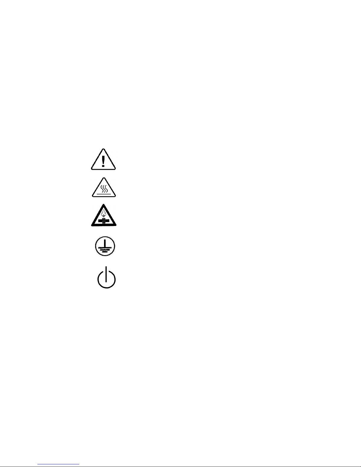
2. SYMBOL DESCRIPTION
Caution! Consult accompanying documents
Caution! Hot surface.
Caution! Hot steam.
Protective earth (Ground)
Stand by

Page 5 of 102 Pages
3. INSTALLATION INSTRUCTIONS
The following utilities have to be connected (Refer to the drawing below ‘Rear View’
of the autoclave).
Power outlet, as detailed in the table below:
Power
3 Ph, 400V/50/60Hz
Recommended Circuit Breaker
20A
If the 3 phase autoclave has to be connected to a one phase power network, 1 x
230V, 50/60Hz., connect the 1ph 230V power source to the supplied switch box
that has a 1 phase input (from the power source) and a 3 phase output (to the
autoclave). See details at the end of this manual.
The power network must be protected by a current leakage relay.
Mineral-free water having a conductibility lower than 15µs (microsiemens),
through a 1/2” flexible hose.
To obtain water quality meeting requirements a deionization column or reverse
osmosis apparatus can be installed. The water must be delivered at a pressure of 23bar. A pressure reducer shall be installed at the water source outlet as instructed
below.
For fast cooling (if this option is provided):
Feed water from the water network, pressure 2-3bars, connected through a 1/2”
pipe. A pressure reducer shall be installed at the water source outlet as instructed
below.
Compressed air, from a mobile compressor or compressed air network at pressure
3-4 bars, will be set at 1.6-2bars at the autoclave inlet is to be connected by a
flexible conduit of 3/16”.
The air must be of instrumental quality filtered at 5µ and free of humidity and oil
drops.
Drain connected by 1/2” pipe, located at the rear of the unit. The chamber exhaust
and coolant water is evacuated to an open waste funnel. The drainage piping must
be heat resistant, to 80ºC, non-continuous flow.
Attention:
Connection of water system to the autoclave must be performed through "BACK
FLOW PREVENTION SYSTEM" installation as per EN 1717.
3.1 Installation Site
1. Install the autoclave according to the following guidelines:
2. Place the autoclave on the floor. Verify that the surface is leveled.
3. All utility supplies must be prepared in accordance with requirements,
before autoclave installation e.g. mineral-free and tap water, compressed
air, one or three-phase power network, connection to the drain of the
building.
4. Leave the space free around the autoclave for maintenance and service
requirements.
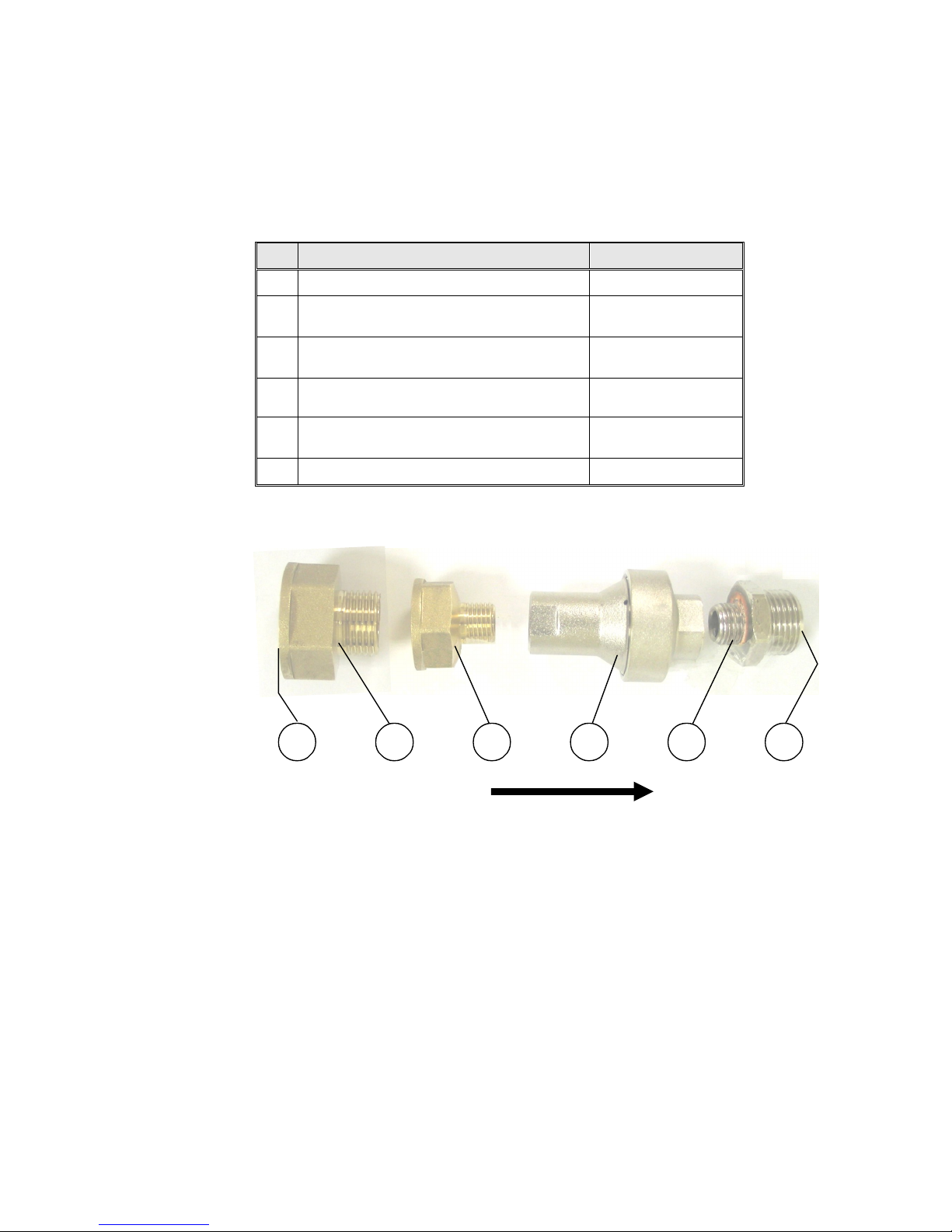
3.2 Connection of the pressure regulator
This paragraph refers to the pressure regulator of the feed water and to the
pressure regulator of the mineral free water.
1. Attach the pressure regulator to the facility's water outlet.
Page 6 of 102 Pages
FLOW DIRECTION
54321
6
2. Connect the supplied flexible hose to the pressure regulator's assembly
outlet and to the autoclave's water inlet.
3. Verify that the pressure regulator is in right direction. The flow direction
is indicated by an arrow stamped on the pressure regulator.
4. Verify that water flows freely in the feed water and in the mineral free
water lines.
No. Description Cat No.
1 Side of water supply source N/A
2
Reducer, Female 3/4" BSP to Male
1/2" BSP, Brass
FIT100-0424
3
Reducer, Female 1/2" BSP to Male
1/4" BSP, Brass
FIT100-0425
4
Pres
sure Regulator, Water, In
-
Line,
with Strainer, 1/4 x 1.5 bar
GAU029-0059
5
Fitting, Adaptor, M 1/2" BSP x M 1/4"
BSP, Brass Ni plated
PNE100-0042
6 Side of flexible hose (to autoclave N/A
Page 7 of 102 Pages
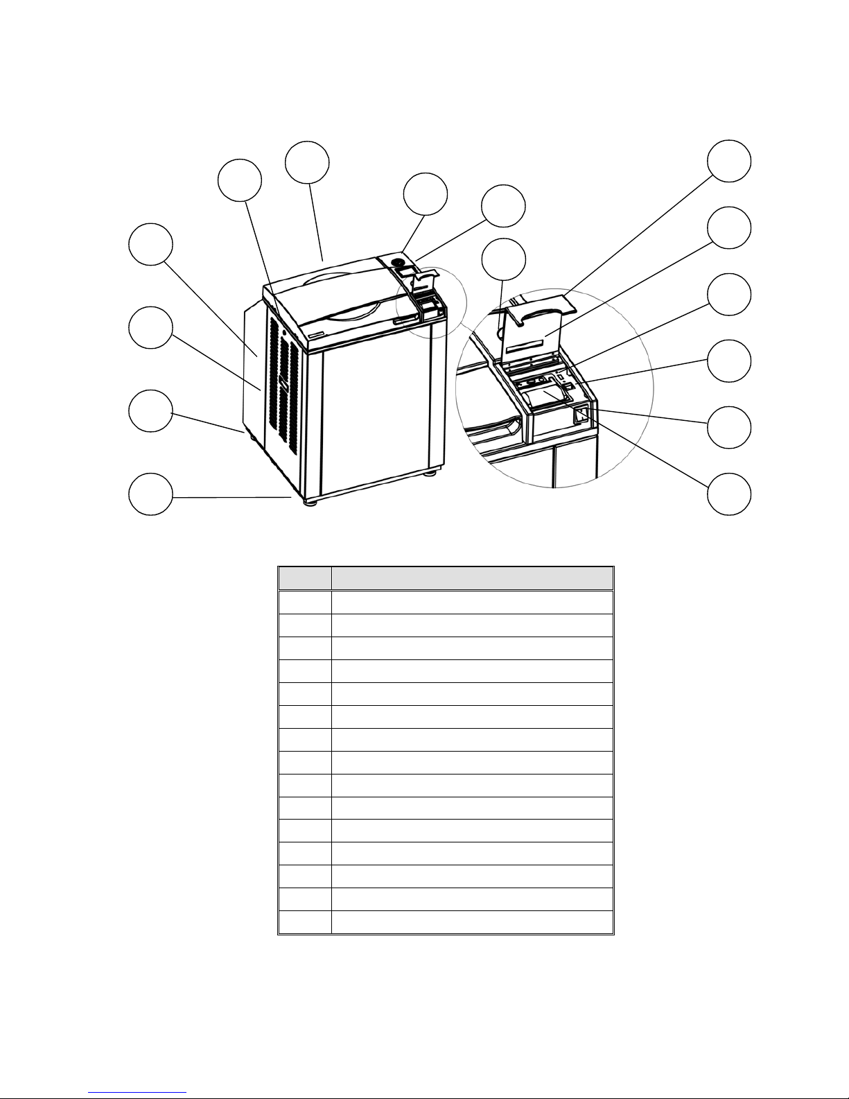
FRONT VIEW
No. Description
1 Front leg
2 Rear leg
3 Left service door
4 Left service door grip
5 Left service door lock
6 Door cover
7 Pressure gauge
8 Display
9 Keyboard
10 Printer cover
11 Paper slot and paper cutter
12 USB socket
13 RJ45 connector
14 Main switch
15 Printer
9
10
5
6
7
8
11
14
15
4
3
2
1
12
13
Page 8 of 102 Pages
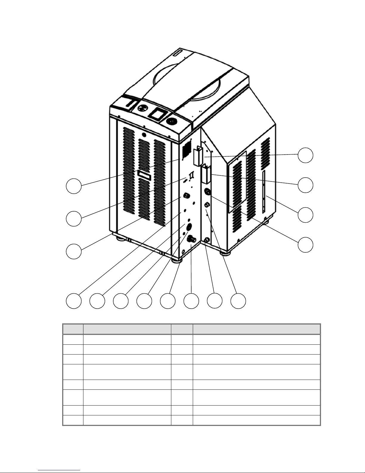
REAR VIEW
No. Description
No. Description
1 fan grill 9
air pressure regulator
2 circuit breaker 10
generator drain outlet
3 electrical cord
11 Generator mineral free water inlet
4
Vacuum pump city (tap)
water inlet
12 generator pressure gauge
5 compressed air inlet
13 side gage glass indicator tube
6
Tap water inlet for cooling
coil and drain
14 generator safety relief valve
7 autoclave air pressure gauge
15 chamber safety relief valve
8 autoclave drain outlet
7810111 2
3
4
5
6
14 131215
9
Page 9 of 102 Pages
4. TESTS
4.1 Installation Tests
The service technician shall perform the following preliminary checks
before operating the autoclave:
a. Integrity Check
Perform a visual check to verify that there are no dents, scratches,
broken gauges, etc.
b Leveling Check
Check that the autoclave is leveled.
c. Leakage current test
Check the precise operation of the earth leakage relay.
d. Continuity Check
Check the continuity of the grounding connection.
At this stage operate the autoclave and continue with the tests:
e. Safety Check
Check the safety elements; safety valve and the door locking mechanisms.
f. Programs Check
Run basic programs of the autoclave and check the operation
sequences, the sterilization parameters etc.
g. Validation
Validate the sterilization cycles, taking in consideration the interface of
packaging/goods/autoclave.
After the above steps are performed, the autoclave is ready for operation.
4.2 Periodical Tests
PERIOD TEST
2 months Test the safety valve by operating it.
6 months
Remove the cover of the autoclave, tighten the, valves and connectors in
the controlbox.
Year
Check the continuity of the grounding connections.
Check the temperature and pressure calibration.
Perform validation of the autoclave.
Check the precise operation of the earth leakage relay.
Check that the autoclave is leveled.
Check the safety elements; safety valve, safety and cut-off thermostats
door locking mechanisms.
Run basic programs of the autoclave and check the operation sequences,
the sterilization parameters etc.
Check the water reservoir, piping, plastic parts and electric wires.
Check and tighten the piping joints to avoid leakage.
Check and tighten all screw connections in the control box, valves and
instrumentation.
Observe the closing device for excessive wear
5 years Observe the closing device for excessive wear
Safety tests (pressure vessel, efficiency, electrical) shall be performed in accordance
with local rules or regulations, by an authorized inspector.
Only an authorized technician shall perform the 6-months and yearly tests!
Page 10 of 102 Pages
Check connections to distilled or mineral free water. Open the distilled or
mineral free water valves. Manually test the distilled or mineral free water
valves by over-riding the appropriate solenoid valves. If there are no leaks, –
leave the water manual inlet taps open.
1. Observe the gauge and see that the generator reaches working pressure.
Check that the jacket pressure gauge, reaches 2.4 bars (35 psi).
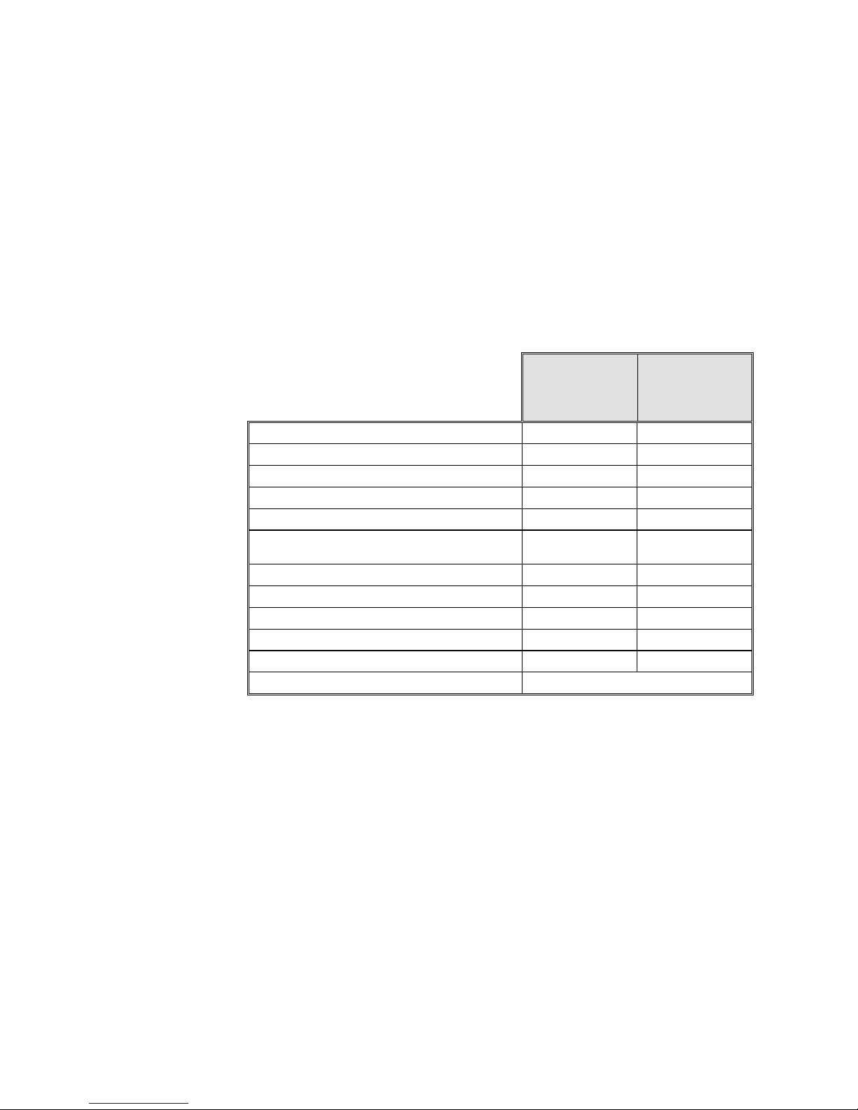
5. WATER QUALITY
Physical Characteristics and Maximum acceptable
contaminant levels in water or steam, for steam generator and
sterilizers
(According to EN 285:2006).
Contaminants
in water
supplied
to generator
Contaminants
in condensate
at steam inlet
to sterilizer
Evaporate residue
≤ 10 mg/l N/A
Silicate (SiO
2
≤ 1 mg/l ≤ 0.1 mg/l
Iron
≤ 0.2mg/l ≤ 0.1mg/l
Cadmium
≤ 0.005 mg/l ≤ 0.005 mg/l
Lead
≤ 0.05 mg/l ≤ 0.05 mg/l
Rest of heavy metals except iron,
cadmium, lead
≤ 0.1 mg/l ≤ 0.1 mg/l
Chloride (Cl)
≤ 2 mg/l ≤ 0.1 mg/l
Phosphate (P2O5)
≤ 0.5 mg/l ≤ 0.1 mg/l
Conductivity (at 25°C)
≤ 5 µs/cm ≤ 3 µs/cm
pH value (degree of acidity)
5 to 7.5 5 to 7
Hardness (Σ ions of alkaline earth)
≤ 0.02 mmol/l ≤ 0.02 mmol/l
Appearance
Colourless, clean, without sediments
Compliance with the above data should be tested in accordance with
acknowledged analytical methods, by an authorized laboratory.
Attention:
We recommend testing the water quality once a month. The use of water
that do not comply with the table above may have severe impact on the
working life of the sterilizer and can invalidate the manufacturer’s
guarantee.
5.1 Water for the Vacuum pump and drain cooling
The feed water supplied to the liquid ring vacuum pump must meet the
following requirements:
Hardness: 0.7 - 0.2 mmol/l.
Water temperature: shall not exceed 15°C.

Page 11 of 102 Pages
Note:
The use of heavy scaled water for the vacuum pump cooling, can cause
blocking of the rotor and put the pump out of operation. This invalidates the
guarantee for the vacuum pump.
5.2 Reverse Osmosis
A Reverse Osmosis system may be used to improve the quality of the water
used to generate steam in the autoclave chamber. The use of mineral free will
contribute to better performance and longer life of the autoclave.
Page 12 of 102 Pages
6. DESCRIPTION OF THE CONTROL SYSTEM.
BLOCK DIAGRAM HARDWARE SOFTWARE COMPONENTS
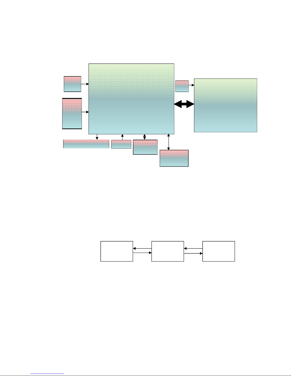
6.1 Application system architecture
The system is divided into three main sections (dll)
1. GUI – holds all the Human Machine interface including the main
application screen and all the configuration screens which enable the user
to handle the machine.
2. Logic – holds all the application logic for running the machine.
3. Utilities – Holds general functionality which is used by the logic section
and the GUI section e.g: converting function for displaying different
pressure or temperature units type, languages etc..
Mapping of the software to the hardware – see Software Development Plan
The Hardware architecture is based on Freescale i.MX27 PDK Evaluation
Board.
GUI LOGIC UTILITY
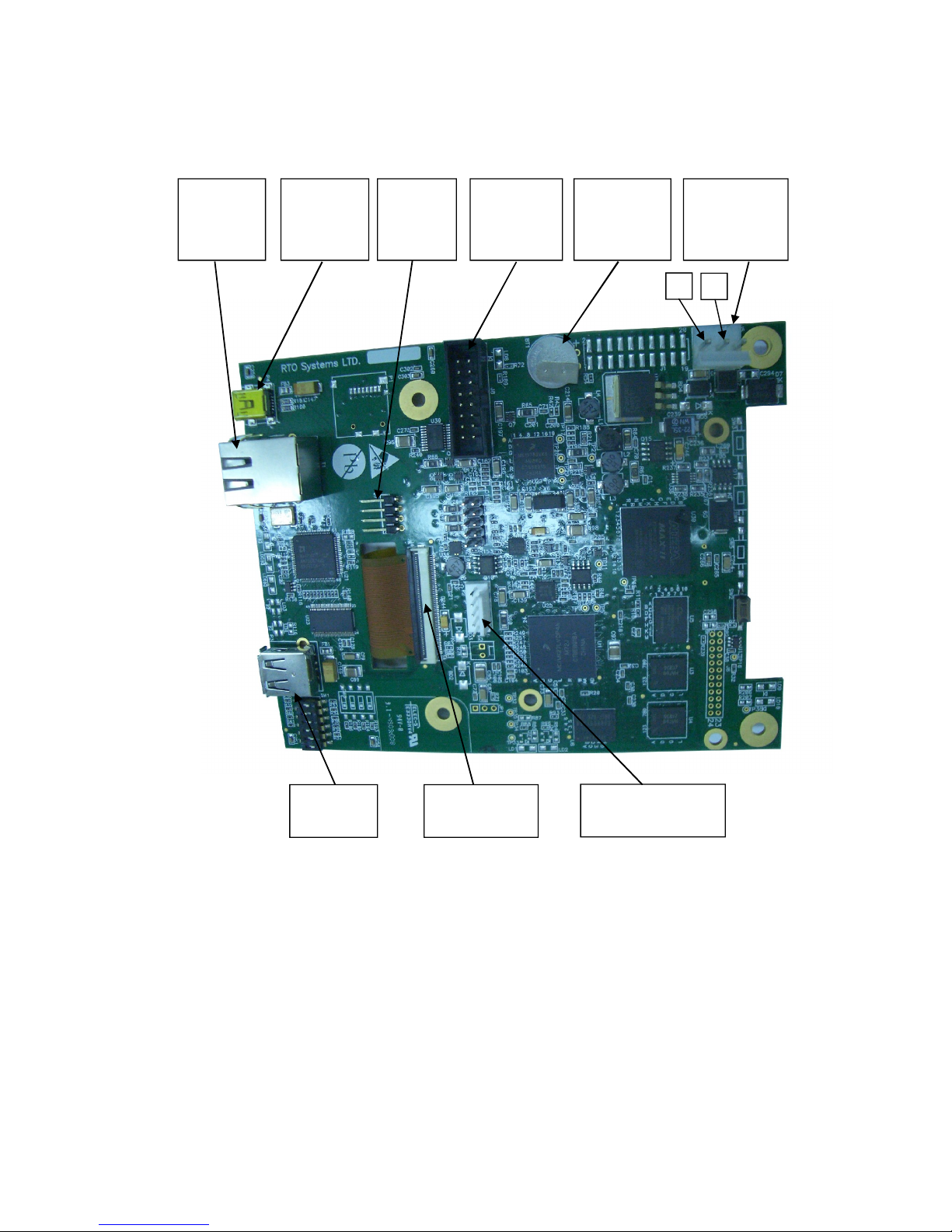
Main board
-CPU +memory- Backup power input
-MCIMX27LVOP4 A+MC13783VK5
-R.T.C (including Battery) M41T81SM6E
-Memory card expansion
MT46H32M16LFBF-
6:B+EPM570F256C5+S71WS256PD0HF3SR0C+K
9F1G08ROB-JIB000
Ethernet
Am79C874
I/O Board
CPU- STM32F103R6T6
-24 Digital Outputs
-2 Analog outputs
-9 Digital inputs
-4 Analog Inputs 4-20mA
-6 Analog inputs Temp pt100
-3 Inputs water level
Keypad
Graphic Display 3.5 "
USB Memory
socket
ISP1504ABS
24/12
VDC
Input
COM1
(RS232)
MAX323
2CSE+
Printer
24/12
VDC
Page 13 of 102 Pages
6.2 Description of the programmable component:
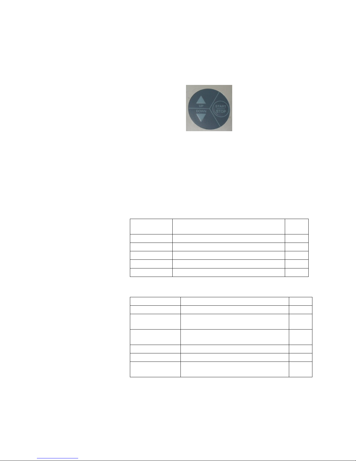
6.2.1 Interfaces to users
Keypad: The keypad has three push buttons:
o Down key
o Up key
o Start/stop key
Display: The control system has a graphical display
USB socket: The USB socket is intended to load cycles'
history from flash a memory (disk on key). The
received file is in txt format that can be loaded
onto a PC.
6.2.2 Inputs and Outputs
6.2.2.1 Analog inputs
Analog
inputs
Description JP
PT100-1 PT-100 Chamber Temperature J2
PT100-2 PT-100 Ref Temperature1 J3
PT100-4 PT-100 Drain (option) J5
Pressure 1 4-20mA main chamber pressure control J7/1
Electrode 1 Water level camber/generator control 1 J11/1
6.2.2.2 Digital inputs
Digital Inputs Description JP
Door 1 closed Indicate door 1 closed J12/1
Door 1 locked
Indicate door 1 locked (3850/70
models)
J12/8
Door1 open
switch
Indicate to command to close / open
Door1 (3850/70 models)
J12/6
Water supply Indicate water supply (Cooling option) J12/2
Air supply Indicate Air supply (Cooling option) J12/4
Distilled water
supply
Indicate distilled water supply J12/3

Page 14 of 102 Pages
-
6.2.2.3 Digital outputs
Digital Outputs Description JP
Generator heaters SSR that operates the chamber heaters J13/6
Water pump /
water valve
Option , relay that operates the water
pump / water valve
J13/10
Vacuum pump /
water to vacuum
pump
Option , relay that operates the
vacuum pump / water to vacuum
pump
J13/12
Vacuum
Option, vacuum valve for pre vacuum
option
J14/2
Compressed air
to chamber
Option, compressed air to chamber
valve for cooling option
J14/4
Top/slow
exhaust
Top/slow exhaust valve J14/6
Fast exhaust Fast exhaust valve J14/8
Atmospheric air Atmospheric air valve J14/10
Cool drain
Option, cool drain valve for cooling
option
J14/12
Steam to
chamber
Steam to chamber valve J14/14
Water to coil
Option, water to coil valve for cooling
option
J14/16
Compressed air
to coil
Option, compressed air to coil valve
for cooling option
J15/2
Closed door 1
Relay that operates the electrical
cylinder to close the door
J15/4
Open door 1
Relay that operates the electrical
cylinder to open the door
J15/6
6.2.3 Actuators
The control system operates electrical valves (solenoids), Electric
cylinder motors, pneumatic cylinders, electric pumps, heaters.
6.2.4 On / off switch
A Rocker Switch 250V AC, 16A
Page 15 of 102 Pages
6.3 Software development plan:
The hardware is consisted of cards: MAIN and IO
6.3.1 Main card
Operating system (MAIN card)
The Operating system is Microsoft Windows CE version 6. The
code to the Operating system is supplied by Microsoft. The
connection code between the Operating system and the
hardware components (BST – Board Support Package) is
supplied by FreeScale. Minimum suitability for this
"Tuttnauer" project is performed in this code.
Development tools (MAIN card)
The software develop environment is on Microsoft Visual
Studio 2005 that includes the Microsoft Platform Builder for
Windows CE 6.0. The specific Tuttnauer system application is
written in C Sharp.net on Microsoft Compact Framework .net
Power Supply
Connector
(24V DC)
Connector to
printer
+
Ethernet
ConnectorSDNot in use
USB
Connector
-
Connector
to IO Board
Connector to
LCD display
Connector
to Keypad
Lithium coin
battery T.H
Horizontal
3V 48mAh
J5
BT1
J8
J4
P2
P4
T1
P3
J3
Page 16 of 102 Pages
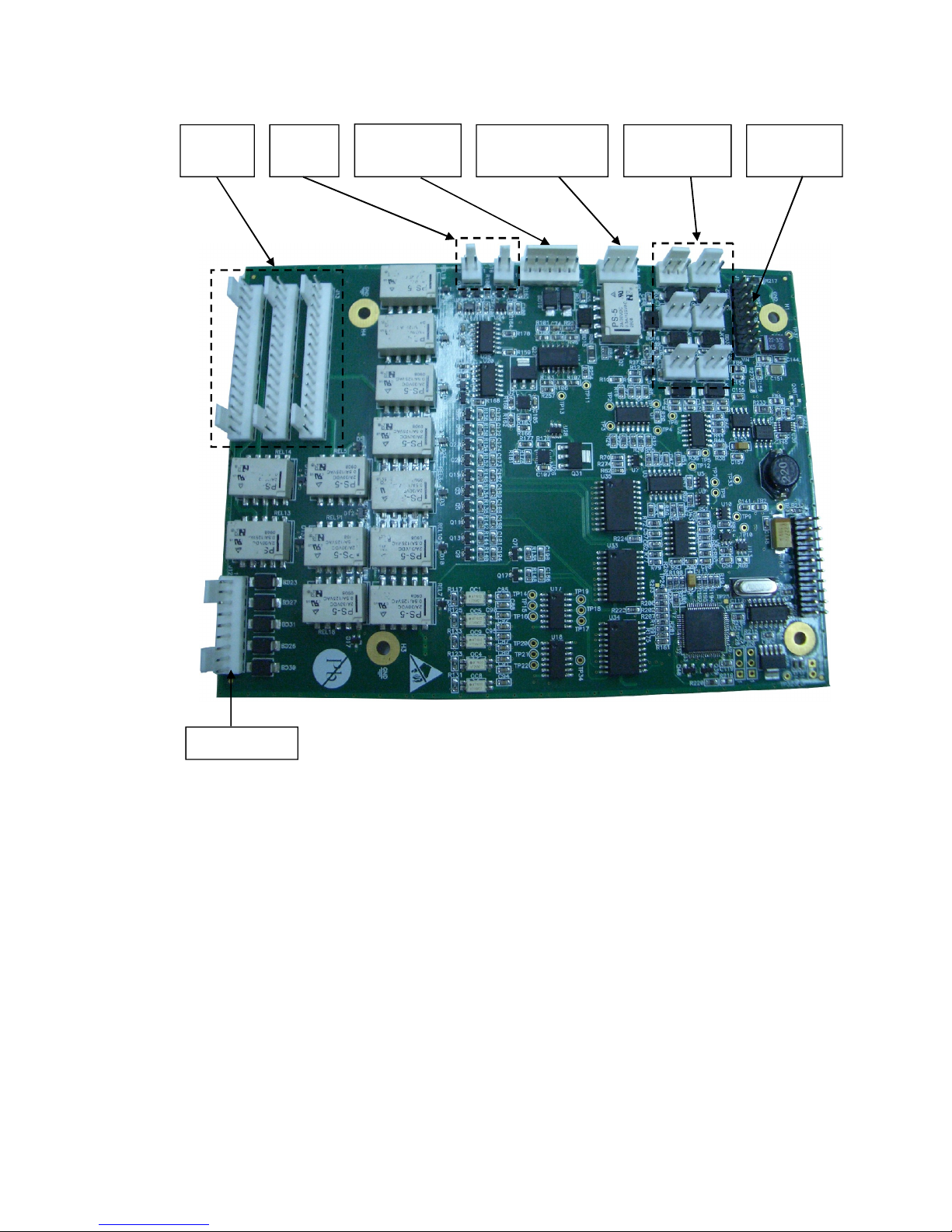
6.3.2 IO Card
IO card is an independent card. It checks the card by a method of a
continuous scan of all the ports, saving the data in the memory and
transporting this data according to the request in the communication
channel RS-232 to the personally adapted protocol.
At the end of the check process of the digital and analog ports, the
communication channel is checked, in case of receiving a request,
the request is checked and if the request is legitimate it will be taken
care of.
The IO card is controlled by the MAIN card. Only when requests
are received from the MAIN, the requests will be checked and
performed.
The IO card will perform an electrical restart of the systems (IO
card) if it does not receive requests within 5 seconds. In the next
request received from the MAIN, the IO card will indicate to the
requester of IO card systems restart.
Analog inputs
(PT-100)
Analog inputs
Pressure (4
-
20mA)
Analog inputs
electrodes
J
J
J6
J3
J4J1
J7J11
J16J17
J13J15J14
Connection to
MAIN Board
Analog
outputs
Digital
outputs
Digital outputs
J12

Page 17 of 102 Pages
The "brain" in the IO card runs on microcontroller type:
STM32F103R6T6.
The Microcontroller is an electrical Integrated circuit with an
actualized complete system (SoC) including a processing unit,
external interfaces, memory, etc.
The Microcontroller is constructed of a number of main
components:
1. Central processing unit – the main component in the
microcontroller is a central processing unit (CPU) This unit is
in charge of receiving the request (command) code from the
memory, deciphering, receiving variable data from the
memories and performing the command.
2. Memory – divided into 2 sections.
2.1 software memory – in this memory the software that
samples the IO card and request (command) from the
user are saved. As this memory is a flash memory it is
possible to burn the code many times (efficient to the
development stage).
2.2 information memory – in this memory the data and other
variables values are saved. This memory is not flash
memory, but is RAM memory.
Digital / Analog ports (in/out) – through them the
microcontroller can receive data of digital/analog
signs from the system, save them and pass them on
respectively to the user request.
Ports (in / out) to the communication – in the IO card
there is a UART component. This component enables
communication with the MAIN card through the RS232 in suitable protocol.

Page 18 of 102 Pages
6.3.3 MAIN and IO cards :communication protocol between IO board
to Main Board
Communication protocol between IO to Main boards is described
below.
The communication manged by the Main board (master), the IO
functions as slave
1. There are six communication functions.
The communication functions (to read or write) identified by
number.
The communication functions listed below:
1.1 01 - Read – command to IO send all the information of
digital analog inputs.
1.2 02 - Write – Command to IO to activate analog and
digital outputs.
1.3 03 - Read version – IO software version to verify the
version.
1.4 04 – N.A.
1.5 05 - Read number that identifies the ID of IO board and
the software version.
1.6 06 - Write (only at the first time) to IO his ID and
software number.
2. First Byte (Byte 1).
The first byte identifies ID functionality request. It can be one
of the numbers in a paragraph.
3. The second byte will present the data size if the main board
asks to write information to the IO. If the request is to read this
byte will be 00.
4. The number of the request. This number is increased from 00ff.
5. Check sum of the package – to prevent mail functionality of the
board if there is interference in communication.
6. The information package transfer. The information contains
number of the input or output and data for/from each I/O.
Bytes identify number of input or output followed by two bytes
containing the data of the input or outputs.
7. Last byte contains a check sum of the entire package that is
transferred. This is to verify that the information is not
corrupted.
Example
The main board sends:
01;00;0003;0004;
01 Ask to Read inputs.
00 not transfer information.
0003 Request number 3
0004 Checksum to verify the request
Page 19 of 102 Pages
7. CHECKING AND CHANGING PARAMETERS AND OTHER DATA
The control system prevents changing programs if the door is closed. This protection
is intended to avoid program changes if the autoclave is loaded. If the operator for
example inserts the load into the chamber, closes the door and leaves the room and
another operator/user tries to change the program, the operator/user will not be able to
do this unless the door is opened and the load inside the chamber can be seen.
7.1 Directories and subdirectories
The Technician may perform the following:
DIRECTORY SUBDIRECTORY
SECOND
SUBDIRECTORY
Cycle Parameters –
applicable only for Custom
1 and Custom 2 programs
See sec. 6.4 “Cycle Parameters
(Custom 1)”
System Parameters
Print Rate All
Print Rate Sterilization
Screen Saver
Inputs / Outputs
View digital inputs state
View digital outputs state
Test digital outputs
View analog inputs state
History
View old cycle history
Last 10 cycles
Last 50 cycles
All cycles history
Export history to USB
Maintenance
set date and time
Export gain offset to USB
Reset atmospheric pressure
Test RTC
Printer test
Print all gain and offset
Advanced options
Start cycle by clock
Enable cycles
Set language
Set Temperature units
Set pressure units
Export all settings to USB device
Add Custom Program
Set Master IP address
Set mac address
Version information
View current version information
View factory default version
information
View previous version information

Page 20 of 102 Pages
9.3.1 PulsNum. – No. of pulses in the prevacuum stage
If the autoclave is not equipped with a vacuum pump – the parameter
value is "0".
Entry Code – 11
Resolution – 1
Minimum Value – 1
Maximum Value – 5
Set
value
Cycle 1-2 3 4 5 6-7
8-9
-
10
11 12 13 14
Value
1 1 1 3 1 1 1 1 1 1
9.3.2 VacDip1 – Vacuum value in the first pulse
Defines the vacuum value in pulse no.1 of the prevacuum stage.
Entry Code – 11
Resolution – 1kpa
Minimum Value – 1kpa
Maximum Value – 90kpa
Set
value
Cycle
1-2 3 4 5 6-7
8-9
-
10
11 12 13 14
Value
25 25 25 25 25 25 25 25 25 18
9.3.3 VacDip2 – Vacuum value in the remaining pulses
This value defines the vacuum in the remaining pulses in the
prevacuum stage (not just pulse no. 2)
Entry Code – 11
Resolution – 1kpa
Minimum Value – 1kpa
Maximum Value – 90kpa
Set
value
Cycle 1-2 3 4 5 6-7
8-9-
10
11 12 13 14
Value
25 25 25 25 25 25 25 25 25 18
9.3.4 Vac Time 1 – Vacuum Time in the First Pulse
This value defines the time the system will continue to maintain
vacuum for the first pulse after reaching Vac Dip1
Entry Code – 11
Resolution – 30sec
Minimum Value – 1sec
Maximum Value – 1800sec
Set
value
Cycle 1-2 3 4 5 6-7
8-9-
10
11 12 13 14
Value
120 120 120 120 240 120 120 120 120 3
Page 21 of 102 Pages
9.3.5 Vac Time2– Vacuum Time in the remaining pulses.
This value defines the time the system will continue to maintain
vacuum after reaching Vac Dip2 for the remaining pulses.
Entry Code – 11
Resolution – 30sec
Minimum Value – 1sec
Maximum Value – 1800sec
9.3.6 Puls Press – pulse pressure during pre-vacuum stage.
This parameter is used to set the maximum pressure in each pulse of
the pre-vacuum stage.
Access Code – 13
Resolution – 5
Minimum Value – 75
Maximum Value – 200
Set
value
Cycle
1-2 3 4 5 6-7
8-9-
10
11 12 13 14
Value
140 140 140 140 140 140 140 140 140 140
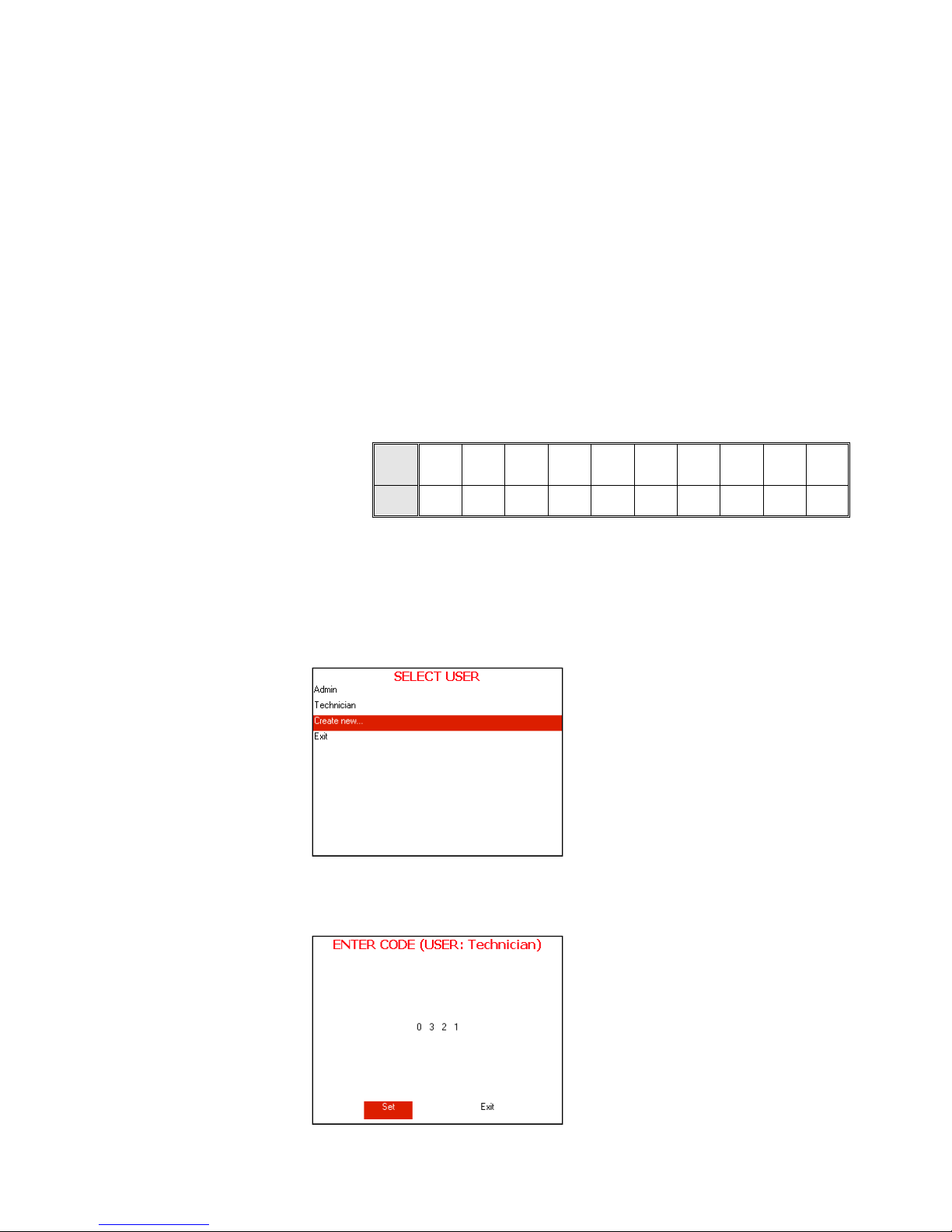
7.2 Entering the main menu
1. Enter the SELECT USER screen by pressing the UP and DOWN keys
simultaneously.
To exit the SELECT USER screen move the cursor to Exit by pressing
UP or DOWN keys and then press START/STOP key.
SELECT USER screen will be displayed.
2. Move the cursor to Admin and press START/STOP key. The following
screen will be displayed:
Page 22 of 102 Pages
3. 0000 is displayed on the screen with the cursor blinking on the right
digit.
4. To increase or decrease the digits, press the UP or DOWN keys.
5. After changing the code to 0321 move the cursor to Set by pressing the
START/STOP key.
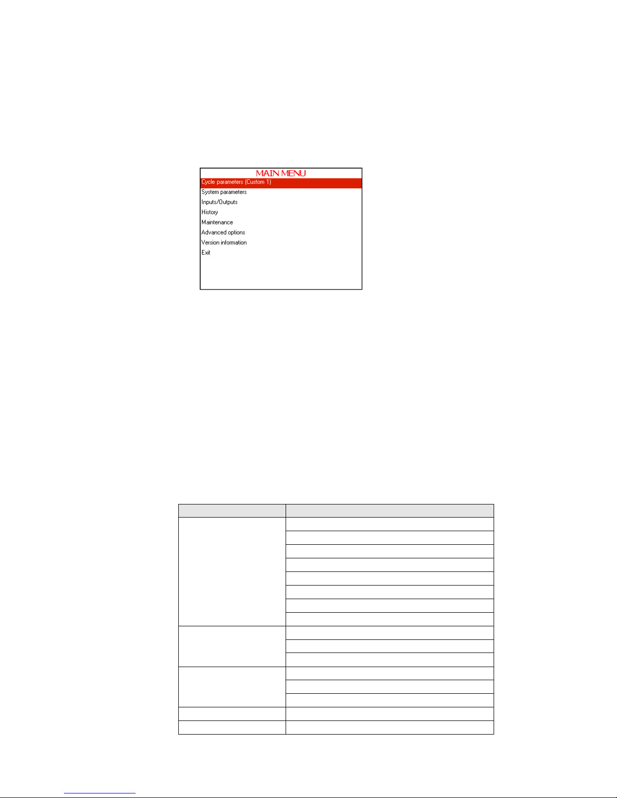
6. When Set is blinking, press the UP or DOWN keys to enter the MAIN
MENU of the autoclave.
The following screen will be displayed:
In order to exit the ENTER CODE screen move the cursor to Exit by
pressing START/STOP Key. when Exit is blinking press UP or
DOWN keys.
7. To browse through the directories, use the UP or DOWN keys.
8. When the required directory is blinking, press the START/STOP key.
The required screen will be displayed.
9. In order to exit this screen follows one of the next:
Move the cursor to Exit with the UP or DOWN keys and select it
by pressing the START/STOP key.
Press the UP and DOWN keys simultaneously.
7.3 Cycle Parameters (Custom 1)
This directory applicable only for custom 1 and custom 2 programs
Subdirectory Property
Create Pulse
Pulse A Count
Pulse A Stay Time
Pulse A Low Pressure
Pulse A High Pressure
Pulse B Count
Pulse B Stay Time
Pulse B Low Pressure
Pulse B High Pressure
Sterilization
Sterilization Temperature
Sterilization Time
F0 Mode
Cooling
Cool mode
Cool End Temperature
Cool Exhaust Rate
Exhaust Exhaust Mode
Dry Dry Heat On 1
Page 23 of 102 Pages
Dry Heat Off 1
Dry first stage time
Dry Heat On 2
Dry Heat Off 2
End
End Temperature
Multiple Cycles
Multiple Cycles Gap
This directory includes seven subdirectories
These subdirectories enable to see and change the cycle parameters.
Therefore it is necessary to choose the required cycle before entering the
"MAIN MENU".
For seeing or changing the parameters proceed as follows:
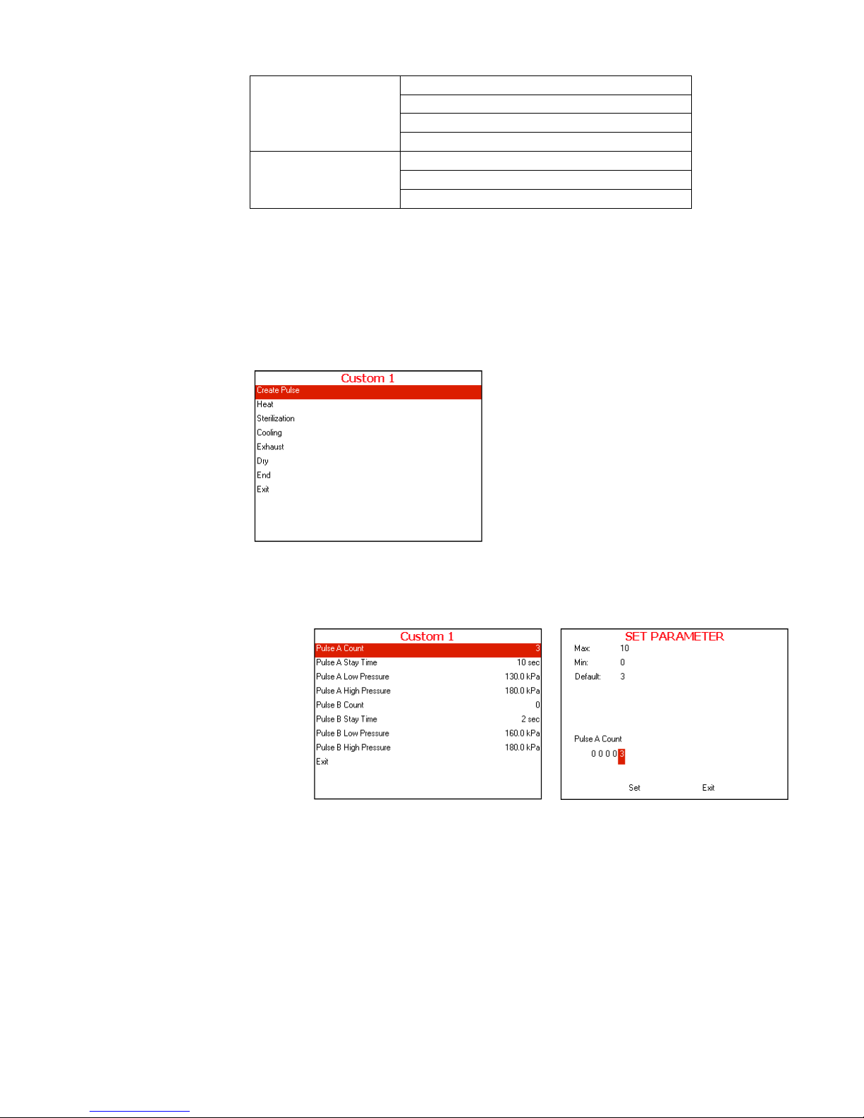
Choose and enter cycle parameters
The following screen will display:
7.3.1 Create Pulse
7.3.1.1 Pulse A Count
Choose and enter Pulse A Count
SET PARAMETER screen will be displayed
Set the required value, move to Set and press UP or
DOWN keys to confirm the parameter value.
In order to exit move the cursor to Exit and press UP or
DOWN keys
7.3.1.2 Pulse A Stay Time
Repeat the action mention in 7.4.1.1 Pulse A Count
Typical display for
Create Pulse
subdirectory
Page 24 of 102 Pages
7.3.1.3 Pulse A Low Pressure
Repeat the action mention in 7.4.1.1 Pulse A Count
7.3.1.4 Pulse A High Pressure
Repeat the action mention in 7.4.1.1 Pulse A Count
7.3.1.5 Pulse B Count
Repeat the action mention in 7.4.1.1 Pulse A Count
7.3.1.6 Pulse B Stay Time
Repeat the action mention in 7.4.1.1 Pulse A Count
7.3.1.7 Pulse B Low Pressure
Repeat the action mention in 7.4.1.1 Pulse A Count
7.3.1.8 Pulse B High Pressure
Repeat the action mention in 7.4.1.1 Pulse A Count
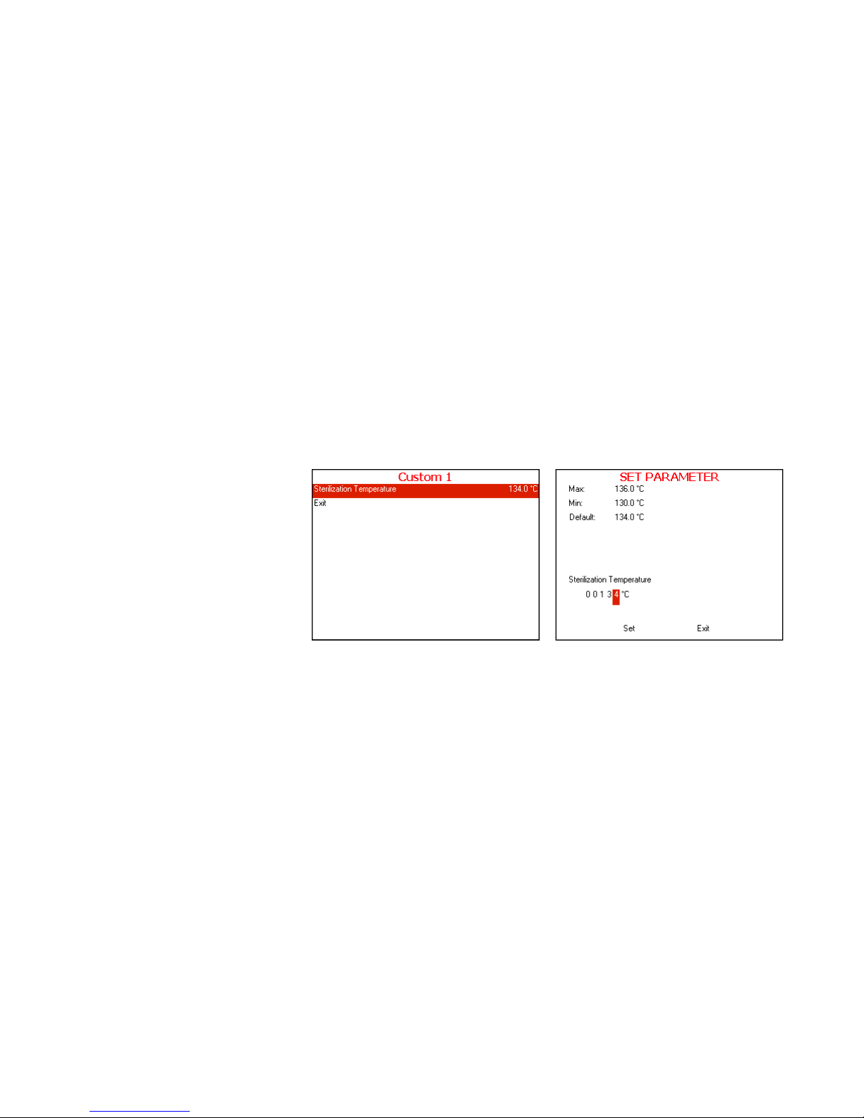
7.3.2 Heat
7.3.2.1 Sterilization Temperature
Choose and enter Sterilization Temperature
SET PARAMETER screen will be displayed
Set the required value, move to
Set and press UP or
DOWN keys to confirm the parameter value.
In order to exit move the cursor to Exit and press UP or
DOWN keys
7.3.3 Sterilization
7.3.3.1 Sterilization Temperature
See 7.4.2.1 Sterilization Temperature
7.3.3.2 Sterilization Time
Repeat the action mention in 7.4.2.1 Sterilization
Temperature
7.3.3.3 F0 Mode
Repeat the action mention in 7.4.2.1 Sterilization
Temperature
Typical display for
Sterilization Temperature
subdirectory
Page 25 of 102 Pages
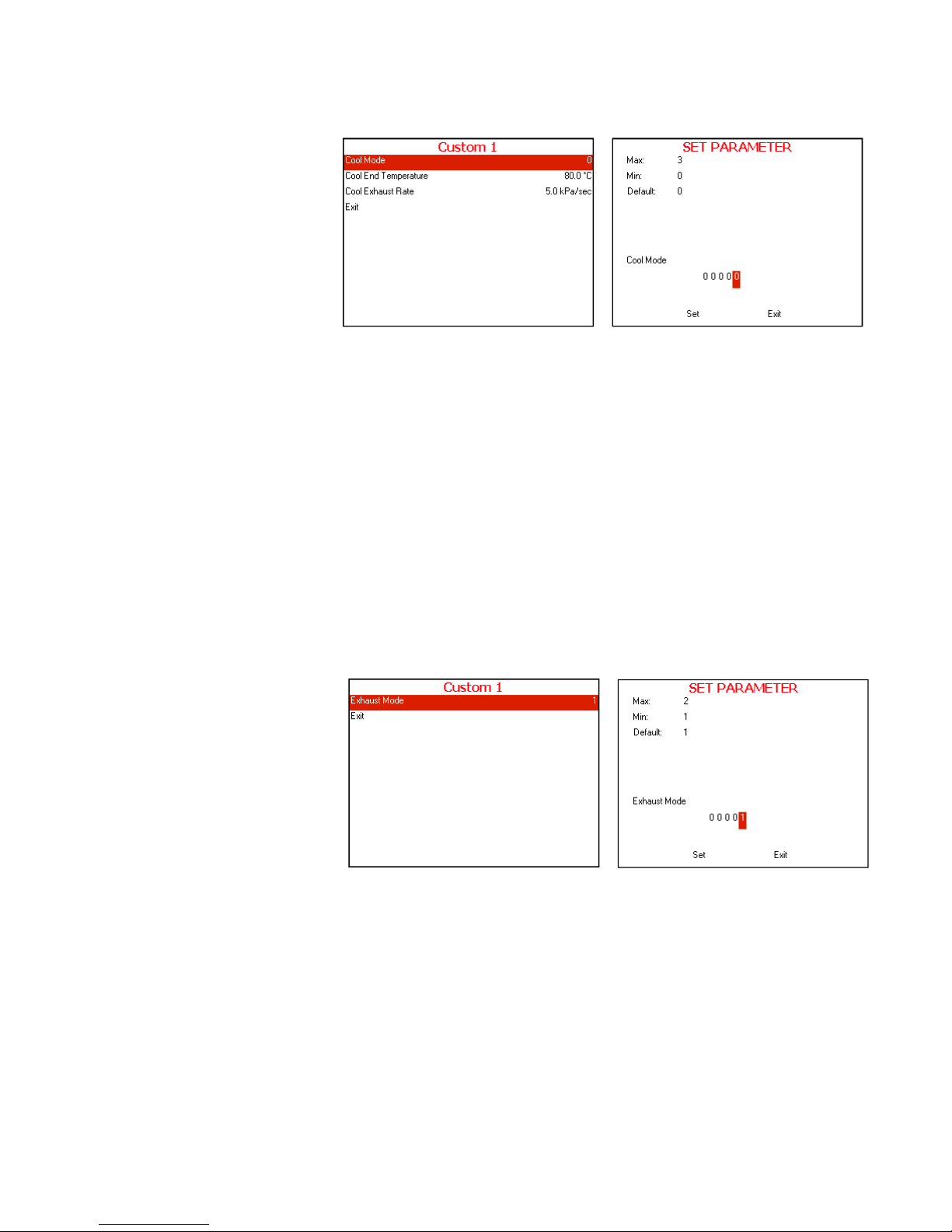
7.3.4 Cooling
7.3.4.1 Cool Mode
Choose and enter Cool Mode
SET PARAMETER screen will be displayed
Set the required value, move to Set and press UP or
DOWN keys to confirm the parameter value.
In order to exit move the cursor to Exit and press UP or
DOWN keys
7.3.4.2 Cool End Temperature
Repeat the action mention in 7.4.4.1 Cool Mode
7.3.4.3 Cool Exhaust Rate
Repeat the action mention in 7.4.4.1 Cool Mode
7.3.5 Exhaust
Exhaust Mode
Choose and enter Exhaust Mode
SET PARAMETER screen will be displayed
Set the required value, move to Set and press UP or
DOWN keys to confirm the parameter value.
In order to exit move the cursor to Exit and press UP or
DOWN keys
Typical display for
Cool Mode
subdirectory
Typical display for
Exhaust Mode
subdirectory

Page 26 of 102 Pages
7.3.6 Dry
7.3.6.1 Dry Heat On 1
Choose and enter Dry Heat On 1
SET PARAMETER screen will be displayed
Set the required value, move to Set and press UP or
DOWN keys to confirm the parameter value.
In order to exit move the cursor to Exit and press UP or
DOWN keys
7.3.6.2 Dry Heat Off 1
Repeat the action mention in 7.4.6.1 Dry Heat On 1
7.3.6.3 Dry first stage time
Repeat the action mention in 7.4.6.1 Dry Heat On 1
7.3.6.4 Dry Heat On 2
Repeat the action mention in 7.4.6.1 Dry Heat On 1
7.3.6.5 Dry Heat Off 2
Repeat the action mention in 7.4.6.1 Dry Heat On 1
7.3.7 End
7.3.7.1 End Temperature
Choose and enter End Temperature
SET PARAMETER screen will be displayed
Set the required value, move to Set and press UP or
DOWN keys to confirm the parameter value.
In order to exit move the cursor to Exit and press UP or
DOWN keys
Typical display for
Dry Heat On 1
subdirectory
Typical display for
End
Temperature
subdirectory
Page 27 of 102 Pages
7.3.7.2 Multiple Cycles
Repeat the action mention in 7.4.7.1 End Temperature
7.3.7.3 Multiple Cycles Gap
Repeat the action mention in 7.4.7.1 End Temperature
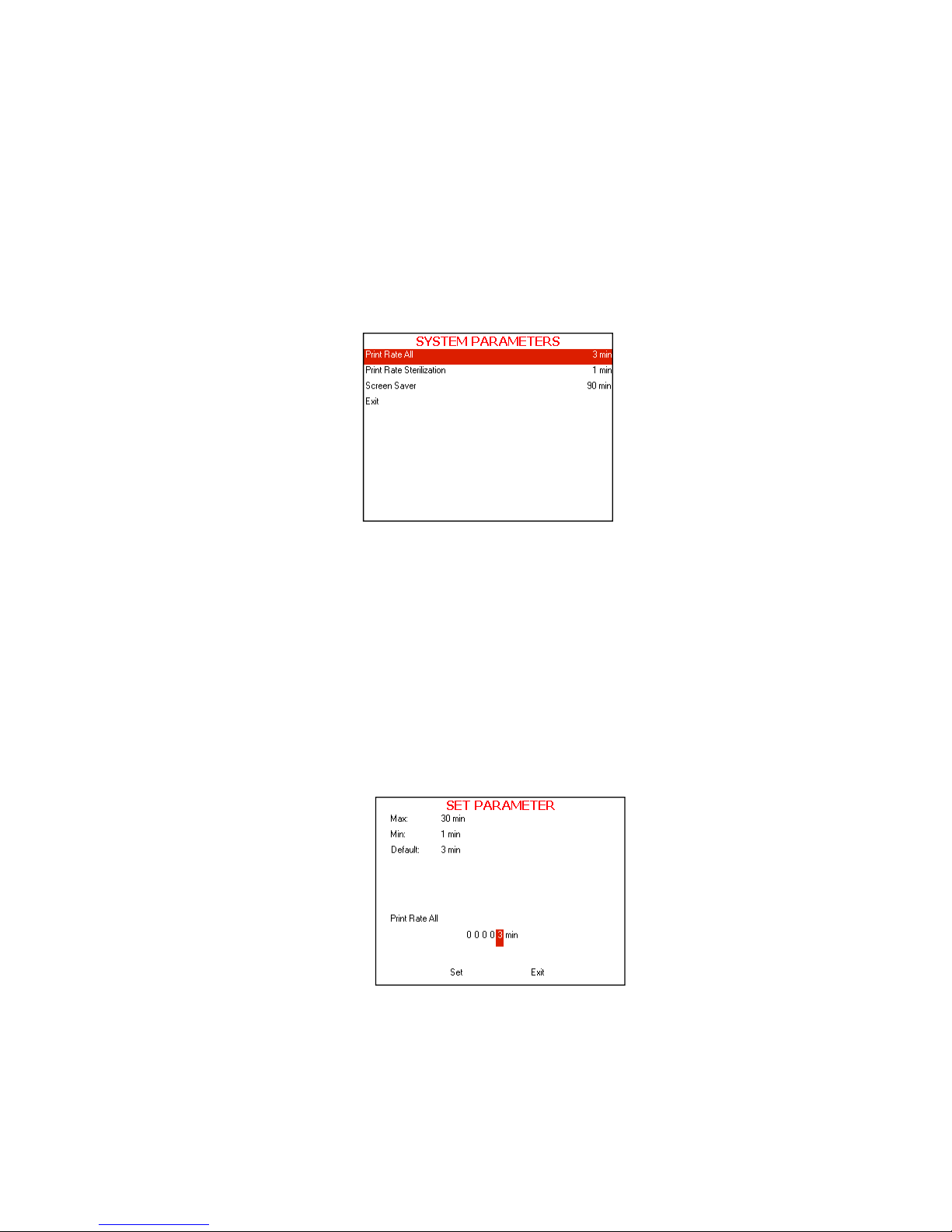
7.3.8 System Parameters
This directory includes three subdirectories
The following screen will be displayed when entering SYSTEM
PARAMETERS
directory:
1. In order to enter to the sub directories move the cursor by
pressing
UP or DOWN keys to the required item and press
START/STOP key
2. In order to exit this screen follows one of the next:
Move the cursor to Exit with the UP or DOWN keys and
select it by pressing the START/STOP key.
Press the UP and DOWN keys simultaneously.
7.3.9 Print Rate All
This subdirectory enables to change the printing rate during the
whole cycle except sterilization stage
1. To increase or decrease the digits, press the UP or DOWN
keys.
2. After changing the value move the cursor to Set by pressing the
START/STOP key.
3. When Set is blinking, press the UP or DOWN keys in order to
confirm changes and return to the previous screen.
4. In order to exit this screen follows one of the next:

Page 28 of 102 Pages
In order to exit this screen move the cursor to Exit with the
START/STOP key and select it by pressing the UP or
DOWN keys.
Press the UP and DOWN keys simultaneously.
7.3.10 Print Rate Sterilization
This subdirectory enables to change the printing rate during
sterilization stage
1. To increase or decrease the digits, press the UP or DOWN
keys.
2. After changing the value move the cursor to Set by pressing the
START/STOP.
3. When Set is blinking, press the UP or DOWN keys in order to
confirm changes and return to the previous screen.
4. In order to exit this screen follows one of the next:
In order to exit this screen move the cursor to Exit with the
START/STOP key and select it by pressing the UP or
DOWN keys.
Press the UP and DOWN keys simultaneously.
7.3.11 Screen Saver
This subdirectory enables the operator to set the screen saver time.
The default time value is 90 minutes. It is possible to increase or
decrease the time value up to a maximum of 600 minutes or down
to a minimum 0 minutes.
When entering the Screen Saver screen, t he time will be
displayed. The cursor is blinking on the "minute" digit.
The time is displayed in the form “0000” min.
 Loading...