

Page 1

Technician Manual
Electronic Laboratory Autoclaves
Models 3840, 3850, 3870 ELVG-D
ELVG-D: standard autoclave
C: optional system for fast cooling
PV: optional vacuum pump
BH: optional bio hazard filtration
F: optional fan for super-fast cooling
The Netherlands Tel: 31 (0) 765423510, Fax: 31 (0) 765423540
Cat. No. MAN205-0491000EN Rev. F
Tuttnauer Europe B.V.,
Hoeksteen 11 4815 PR P.O. Box 7191 4800 GD Breda,
Page 2

http://www.tuttnauerusa.com/
Page 3

Page 1
Table of Contents
Paragraph , page no.
1. Introduction 4
2. Installation Instructions 6
2.1 Installation Site 7
2.2 Connection of the pressure regulator 7
2.3 Front View 9
2.4 Front View for the Fan Configuration 10
2.5 Rear View 11
3. Tests 12
3.1 Installation Tests 12
3.2 Periodical Tests 12
4. Technical Data 14
4.1 Directives and Standards 14
4.2 Water Quality 14
4.3 Reverse Osmosis 15
4.4 Electrical data 16
4.5 Specifications 17
4.6 Overall Dimensions 18
4.7 Construction 18
4.8 Utilities 19
4.9 Symbol Description 20
5. Description of the Control System. 21
5.1 Hardware Control System Components: Block Diagram ................... 21
5.2 Application System Architecture 21
5.3 Interfaces to Users 22
5.4 Inputs and Outputs 22
5.5 Hardware Control System components 24
6. Checking and Changing Parameters and Other Data 28
6.1 Browsing through the menus 28
6.2 Changing a Parameter 29
6.3 Quick options screen 31
6.4 Logging in and entering the Main menu 37
6.5 Directories and subdirectories 38
6.6 System Parameters 41
6.7 Inputs/Outputs 43
6.8 Maintenance 49
6.9 Advanced Options 53
6.10 Version handling 59
Page 4

Page 2
6.11 Cycle parameters 61
6.12 Temperature sensors 63
6.13 Displayed inputs 64
6.14 Purge (generator models only) 65
6.15 Create Pulse 65
6.16 Keep Heat 67
6.17 Heating 68
6.18 Sterilization 68
6.19 Cooling (“C” models only) 69
6.20 Exhaust 70
6.21 Drying 70
6.22 Ending 72
6.23 Global (for some models only) 72
7. Generator description 75
7.1 Generator Electrical Safety System 76
7.2 The Water Pump for the Steam Generator 77
7.3 GICAR Water Level Controller 77
8. Maintenance and Replacement Procedures: the Autoclave 79
8.1 Preliminary Operations for Each Technician Call 79
8.2 Replacing the Circuit Breaker 80
8.3 Replacing the Safety Valve 81
8.4 Replacing the door gasket 83
8.5 Replacing the door cover 84
8.6 Replacing the Printer 89
8.7 Replacing the Door Micro-Switch 1 91
8.8 Replacing the Door Micro-Switch 2 91
8.9 Replacing the air filter 92
8.10 Replacing the locking motor 93
8.11 Replacing the Plunger or Coil of the 1/4" Solenoid Valve
9
5
8.12 Replacing the Plunger or Coil of the BACCARA Solenoid Valve 96
8.13 Replacing the Mechanic Pressostat 96
8.14 Replacing the Pressostat 0.2 (NC) 97
8.15 Replacing the power supplies, water level board and relays
98
9. Maintenance and Replacement Procedures: the Generator 103
9.1 Access to Generator 103
9.2 Draining the generator 103
9.3 Cleaning and Replacing the Water Level Electrodes 104
9.4 Replacing the Heating Elements 106
Page 5

Page 3
9.5 Replacing the Generator Side Gauge Glass Indicator Tube 106
9.6 Replacing the Generator Thermostat 108
9.7 The Water Pump Replacement 110
9.8 Releasing the Vacuum Pump Rotor 110
10. Troubleshooting 112
10.1 Autoclave Troubleshooting 112
10.2 Steam Generator Troubleshooting 117
11. List of Spare Parts 120
11.1 Water Outlet Strainer 128
12. Pressure vs Temperature for Saturated Steam 129
13. Valves Numbering 138
14. Drawings 140
14.1 Piping Drawing – Model 3840/3850/70 ELVCG-D 140
14.2 Piping Drawing – Model 3840/3850/70 ELVCPVG-D 141
14.3 Piping Drawing – Model 3840/3850/70 ELVCPVGBH-D
1
42
14.4 Electrical Drawing for The Autoclave 3840-50/3870
ELV(C)(PV)G 380V.......................................................................... 143
14.5 Electrical Wiring Diagram: The Generator 151
14.6 Generator Control Electrical Cascade Diagram 152
Page 6

Page 4
1. Introduction
This manual, together with the operator’s manual, forms the complete
edition of the Operation and Maintenance instructions. This manual is
intended for the use of the technician. It is forbidden for unqualified and
unauthorized personnel to service the autoclave in accordance with the
instructions in this manual. Any unauthorized service may result in the
invalidation of the manufacturer’s guarantee.
The qualified technician shall be an authorized electrician with the right
qualifications in electronics and shall be familiar with the local
technical/electrical regulations.
Available optional configurations
Models of 3870 ELVG-D model range are laboratory sterilizers
designed especially for the sterilization of instruments, liquids, and
other materials in hospital laboratories, medical laboratories, research
institutes, food laboratories and pharmaceutical facilities.
C
A special feature of the ELVCG-D models is the fast cooling stage for
liquids. In this stage pressure in the chamber is increased by means of
compressed air to compensate the fast decreasing of pressure due to
the fast cooling. The fast cooling shortens the time required for safe
handling of bottles.
Note: there is no cooling option for WR configuration
PV
Special feature of ELVCPV-D models is the vacuum pump that enables
air removal prior to sterilization and during the drying stage.
The advantages of the pre-vacuum sterilizer in comparison to the
regular gravity displacement steam sterilizer are as follows:
— Removal of air pockets from packs and porous loads and most kinds of
tubes (rubber, plastic etc.) by vacuum at the first stage of the cycle.
— Better steam penetration into the load; resulting in effective sterilization.
— Better temperature uniformity.
— Better drying of materials with closed doors due to the vacuum
achieved in the chamber at the end of the sterilization cycle.
Page 7

Page 5
A special feature of the autoclave is the fast cooling stage for liquids. In
this stage pressure in the chamber is increased by means of
compressed air to compensate the fast decreasing of pressure due to
the fast cooling. The fast cooling shortens the time required for safe
handling of bottles
There is a configuration equipped with fan that allows to shorten the
cooling operation.
BH
In ELVCPVBH-D (bio-hazard) models, a bio-hazard filter installed in the
chamber enables sterilizing bio-hazard load without contaminating the
surrounding.
Page 8
Page 6
2. Installation Instructions
The following utilities have to be connected (Refer to the drawing below
‘Rear View’ of the autoclave).
Power outlet, as detailed in the table below:
Power
3 Ph, 400V/50/60Hz
Recommended Circuit Breaker
20A
If the 3 phase autoclave has to be connected to a one phase power
network, 1 x 230V, 50/60Hz., connect the 1ph 230V power source to
the supplied switch box that has a 1 phase input (from the power
source) and a 3 phase output (to the autoclave). See details at the end
of this manual.
The power network must be protected by a current leakage relay.
Mineral-free water having a conductibility lower than 15µs
(microsiemens), through a 1/2” flexible hose.
To obtain water quality meeting requirements a deionization
column or reverse osmosis apparatus can be installed. The water must
be delivered at a pressure of 2-3bar. A pressure reducer shall be
installed at the water source outlet as instructed below.
For fast cooling (if this option is provided):
Feed water from the water network, pressure 2-3bars, connected
through a 1/2” pipe. A pressure reducer shall be installed at the water
source outlet as instructed below.
Compressed air, from a mobile compressor or compressed air network
at pressure 3-4 bars, will be set at 1.6-2bars at the autoclave inlet is to
be connected by a flexible conduit of 3/16”.
The air must be of instrumental quality filtered at 5µ and free of
humidity and oil drops.
Drain connected by 1/2” pipe, located at the rear of the unit. The
chamber exhaust and coolant water is evacuated to an open waste
funnel. The drainage piping must be heat resistant, to 80ºC, noncontinuous flow.
Attention:
Connection of water system to the autoclave must be performed
through "BACK FLOW PREVENTION SYSTEM" installation as per
EN 1717.
Page 9
Page 7
2.1 Installation Site
1. Install the autoclave according to the following guidelines:
2. Place the autoclave on the floor. Verify that the surface is leveled.
3. All utility supplies must be prepared in accordance with requirements,
before autoclave installation e.g. mineral-free and tap water,
compressed air, one or three-phase power network, connection to the
drain of the building.
4. Leave the space free around the autoclave for maintenance and
service requirements.
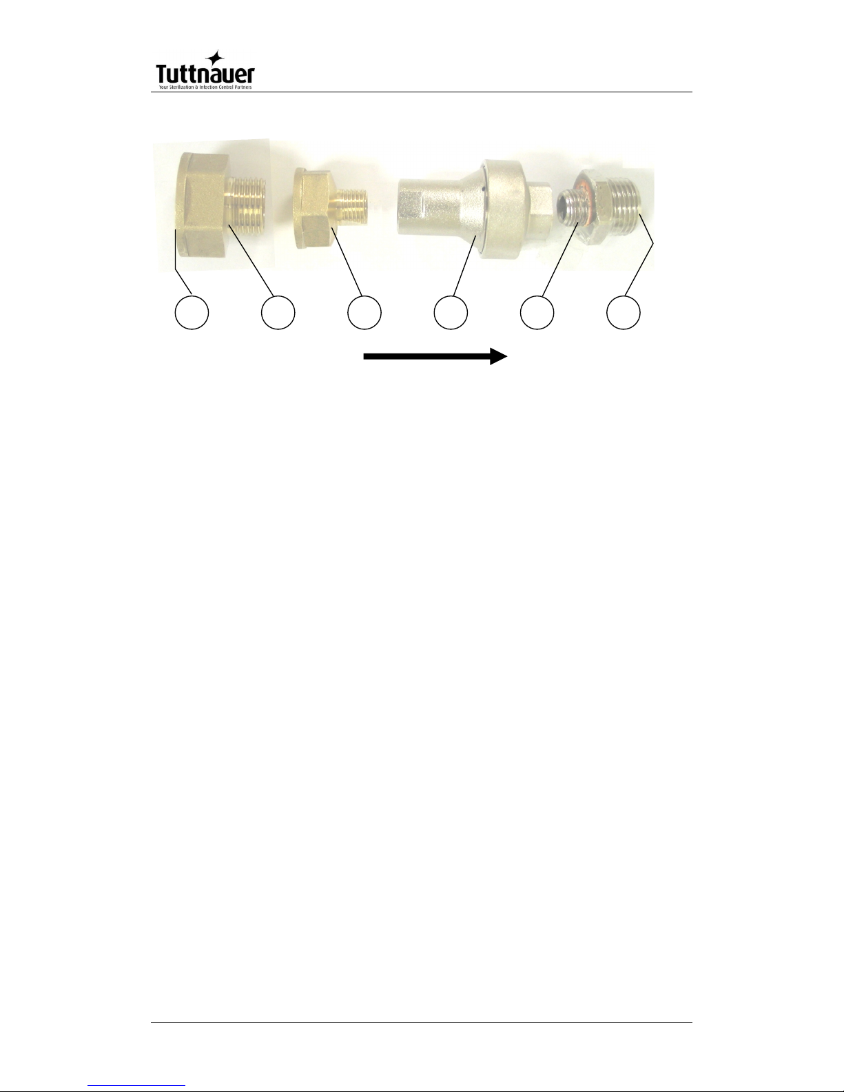
2.2 Connection of the pressure regulator
This paragraph refers to the pressure regulator of the feed water and to
the pressure regulator of the mineral free water.
1. Attach the pressure regulator to the facility's water outlet.
2. Connect the supplied flexible hose to the pressure regulator's assembly
outlet and to the autoclave's water inlet.
3. Verify that the pressure regulator is in right direction. The flow direction
is indicated by an arrow stamped on the pressure regulator.
4. Verify that water flows freely in the feed water and in the mineral free
water lines.
No.
Description
Cat No.
1
Side of water supply source
N/A
2
Reducer, Female 3/4" BSP to Male 1/2" BSP, Brass
FIT100-0424
3
Reducer, Female 1/2" BSP to Male 1/4" BSP, Brass
FIT100-0425
4
Pressure Regulator, Water, In-Line, with Strainer, 1/4
x 1.5 bar
GAU029-0059
5
Fitting, Adaptor, M 1/2" BSP x M 1/4" BSP, Brass Ni
plated
PNE100-0042
6
Side of flexible hose (to autoclave
N/A
Page 10
Page 8
FLOW DIRECTION
54321
6
Page 11
Page 9
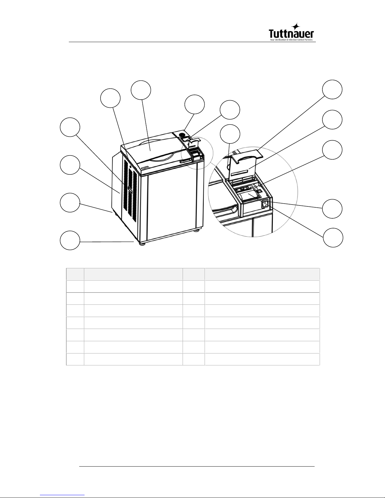
2.3 Front View
No.
Description
No.
Description
1
Front leg
8
Display
2
Rear leg
9
Keyboard
3
Left service door
10
Printer cover
4
Left service door grip
11
Paper slot and paper cutter
5
Left service door lock
12
USB socket
6
Door cover
13
Main switch
7
Pressure gauge
14
Printer
9
10
5
6
7
8
11
14
432
1
12
13
Page 12
Page 10
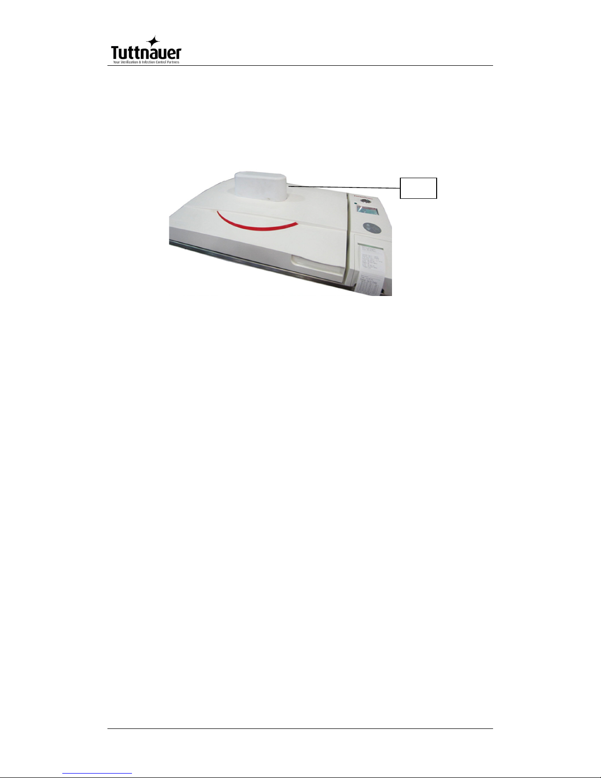
2.4 Front View for the Fan Configuration
There is a configuration equipped with a fan that allows shortening the cooling
operation. The fan is located on the door of the autoclave.
Fan
Page 13
Page 11
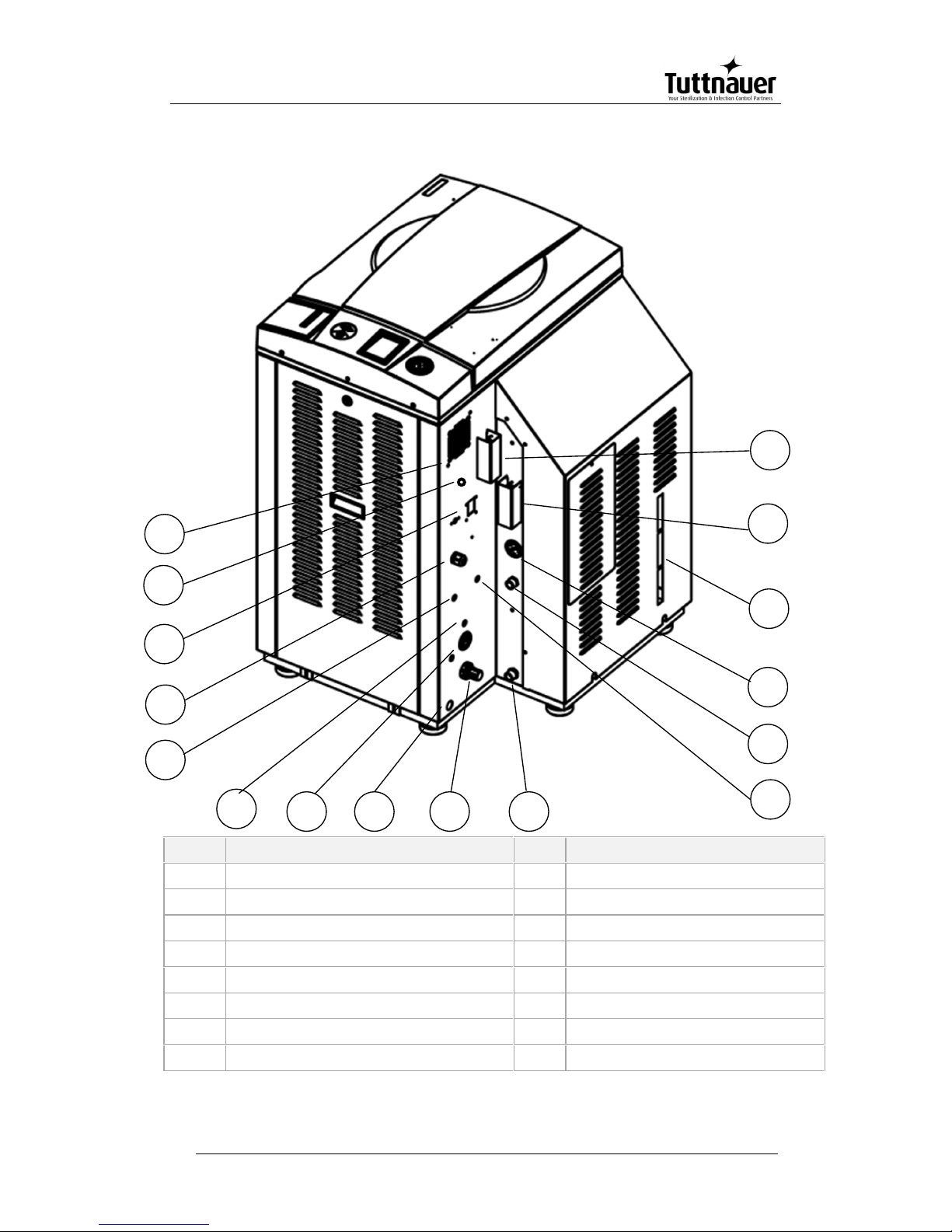
2.5 Rear View
No.
Description
No.
Description
1
fan grill
9
air pressure regulator
2
RJ45 connector
10
generator drain outlet
3
circuit breaker
11
tap water inlet
4
electrical socket
12
mineral free water inlet
5
gravitation valve for vacuum pump
13
generator pressure gauge
6
compressed air inlet
14
side gage glass indicator tube
7
autoclave air pressure gauge
15
generator safety relief valve
8
autoclave drain outlet
16
chamber safety relief valve
6
7
9
1
2
3
5
14
131215
81110
4
16
Page 14
Page 12
3. Tests
3.1 Installation Tests
The service technician shall perform the following preliminary
checks before operating the autoclave:
a. Integrity Check
Perform a visual check to verify that there are no dents, scratches,
broken gauges, etc.
b Leveling Check
Check that the autoclave is leveled.
c. Leakage current test
Check the precise operation of the earth leakage relay.
d. Continuity Check
Check the continuity of the grounding connection.
At this stage operate the autoclave and continue with the tests:
e. Safety Check
Check the safety elements; safety valve and the door locking
mechanisms.
f. Programs Check
Run basic programs of the autoclave and check the operation
sequences, the sterilization parameters etc.
g. Validation
Validate the sterilization cycles, taking in consideration the interface of
packaging/goods/autoclave.
After the above steps are performed, the autoclave is ready for
operation.
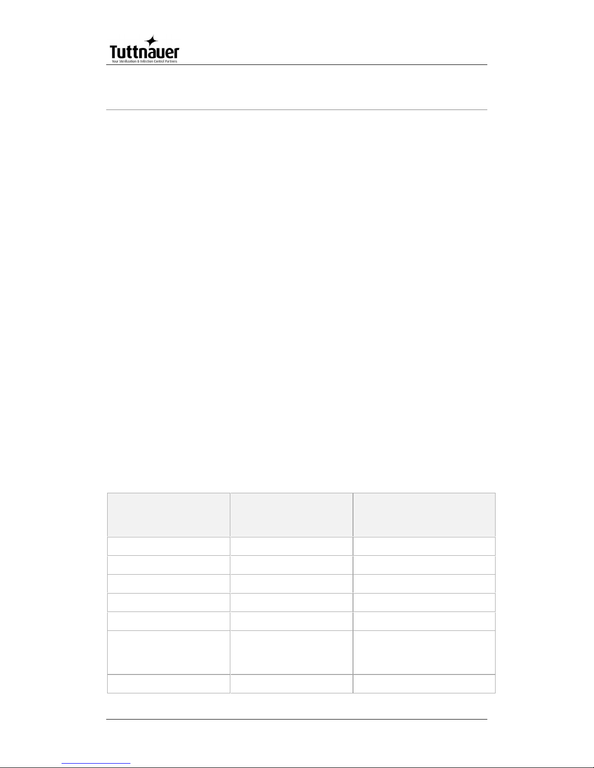
3.2 Periodical Tests
Period
Test
2 months
Test the safety valve by operating it.
6 months
Remove the cover of the autoclave, tighten the, valves and
connectors in the control box.
Year
Check the continuity of the grounding connections.
Check the temperature and pressure calibration.
Page 15
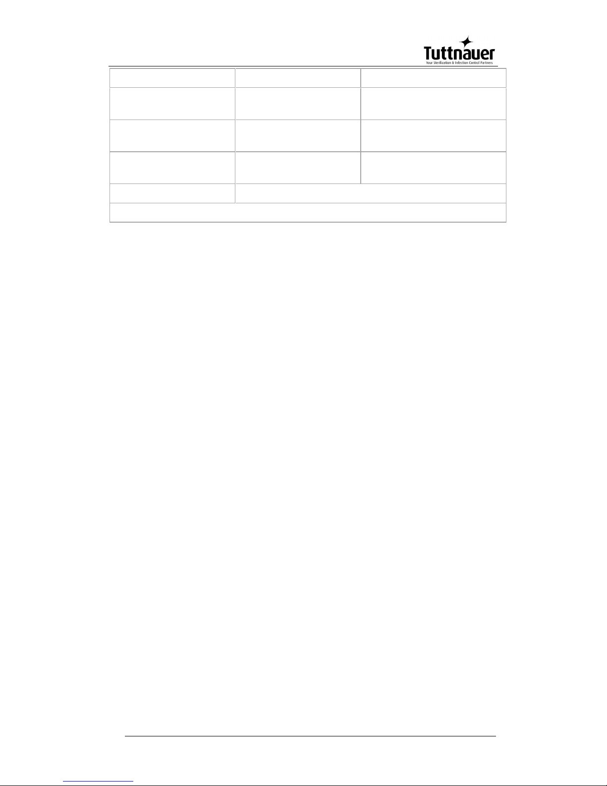
Page 13
Perform validation of the autoclave.
Check the precise operation of the earth leakage relay.
Check that the autoclave is leveled.
Check the safety elements; safety valve, safety and cut-off
thermostats door locking mechanisms.
Run basic programs of the autoclave and check the operation
sequences, the sterilization parameters etc.
Check the water reservoir, piping, plastic parts and electric
wires.
Check and tighten the piping joints to avoid leakage.
Check and tighten all screw connections in the control box,
valves and instrumentation.
Observe the closing device for excessive wear
5 years
Observe the closing device for excessive wear
Safety tests (pressure vessel, efficiency, electrical) shall be performed in
accordance with local rules or regulations, by an authorized inspector.
Only an authorized technician shall perform the 6-months and yearly tests!
Check connections to distilled or mineral free water. Open the
distilled or mineral free water valves. Manually test the distilled or
mineral free water valves by over-riding the appropriate solenoid
valves. If there are no leaks, –leave the water manual inlet taps
open.
Observe the gauge and see that the generator reaches working
pressure.
Check that the jacket pressure gauge, reaches 2.4 bars (35 psi).
Page 16
Page 14
4. Technical Data
4.1 Directives and Standards
Tuttnauer. Ltd. company meets the provisions of the following standards:
ISO 9001:2008 (Quality Systems)
Tuttnauer. Ltd. company also works in conjunction with and refers to:
ANSI/AAMI ST55 American Society of Mechanical Engineers
Section VIII, Division 1, for unfired pressure vessels.
EN 13060 Small Steam Sterilizers.
UL UL 61010-1
PED 97/23EEC
IEC IEC 61010-2-040 Safety
ISO 17665-1:2006 (Validation and Routine Control)
4.2 Water Quality
The distilled or mineral-free water supply shall be according to the table
below:
Physical Characteristics and Maximum acceptable contaminants
levels in water or steam, for steam generator and sterilizers
(According to EN 285: 2006)
Contaminants in
water supplied to
generator
Contaminants in
condensate at steam
inlet to sterilizer
Evaporate residue
≤ 10 mg/l
N/A
Silicate (SiO2)
≤ 1 mg/l
≤ 0.1 mg/l
Iron
≤ 0.2mg/l
≤ 0.1mg/l
Cadmium
≤ 0.005 mg/l
≤ 0.005 mg/l
Lead
≤ 0.05 mg/l
≤ 0.05 mg/l
Rest of heavy metals
except iron,
cadmium, lead
≤ 0.1 mg/l
≤ 0.1 mg/l
Chloride (Cl)
≤ 2 mg/l
≤ 0.1 mg/l
Page 17
Page 15
Phosphate (P2O5)
≤ 0.5 mg/l
≤ 0.1 mg/l
Conductivity (at
25°C)
≤5 µs/cm
≤ 3 µs/cm
pH value (degree of
acidity)
5 to 7.5
5 to 7
Hardness (Σ ions of
alkaline earth)
≤ 0.02 mmol/l
≤ 0.02 mmol/l
Appearance
Colorless, clean, without sediments
[Minimum specific resistivity of 1 megohm per cm (1 M
Ω/cm)]
Compliance with the above data should be tested in accordance with
acknowledged analytical methods, by an authorized laboratory.
Attention: The use of water for autoclaves that do not comply with the table
above may have severe impact on the working life of the sterilizer and
can invalidate the manufacturer’s guarantee.
Use Only deionized water, Having a maximum conductance of 1
microSiemen per cm (1 μS/cm) Tap Water supply
Maximum hardness value 0.7-2.0 mmol/l
The use of soft water is strictly forbidden!
Please consult a water specialist!
4.2.1 Water for the Vacuum pump and drain cooling
The feed water supplied to the liquid ring vacuum pump must meet the
following requirements:
Hardness: 0.7 - 0.2 mmol/l.
Water temperature: shall not exceed 15°C.
Note: The use of heavy scaled water for the vacuum pump cooling, can
cause blocking of the rotor and put the pump out of operation. This
invalidates the guarantee for the vacuum pump.
4.3 Reverse Osmosis
A Reverse Osmosis system may be used to improve the quality of the
water used to generate steam in the autoclave chamber. The use of
mineral free will contribute to better performance and longer life of the
autoclave.
Page 18
Page 16
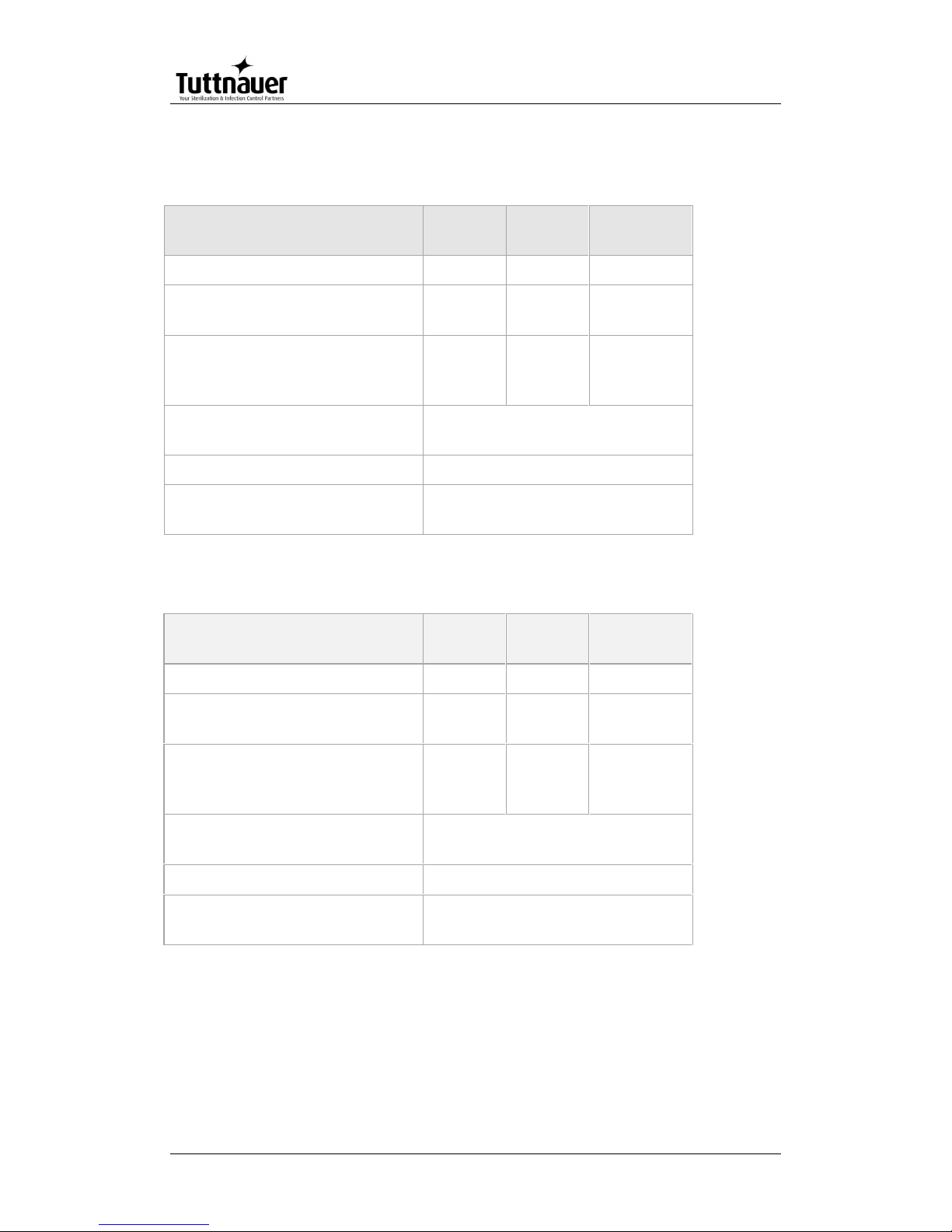
4.4 Electrical data
230V configuration
Property
Value:
3840
Value:
3850
Value:
3870
Total Power
9000
9000
9000
Voltage
1Ph,
230VAC
1Ph,
230VAC
1Ph,
230VAC
Amperage
22A w/o
PV, 25A
with PV
22A w/o
PV, 25A
with PV
22A w/o
PV, 25A
with PV
Protection against electrical
shock
Class I (IEC 60601-1)
Mains supply fluctuation
+/- 10%
Degree of protection by
enclosure
IP31
400V configuration
Property
Value:
3840
Value:
3850
Value:
3870
Total Power
9000
9000
9000
Voltage
3Ph,
400VAC
3Ph,
400VAC
3Ph,
400VAC
Amperage
13A w/o
PV, 16A
with PV
13A w/o
PV, 16A
with PV
13A w/o
PV, 16A
with PV
Protection against electrical
shock
Class I (IEC 60601-1)
Mains supply fluctuation
+/- 10%
Degree of protection by
enclosure
IP31
Page 19
Page 17
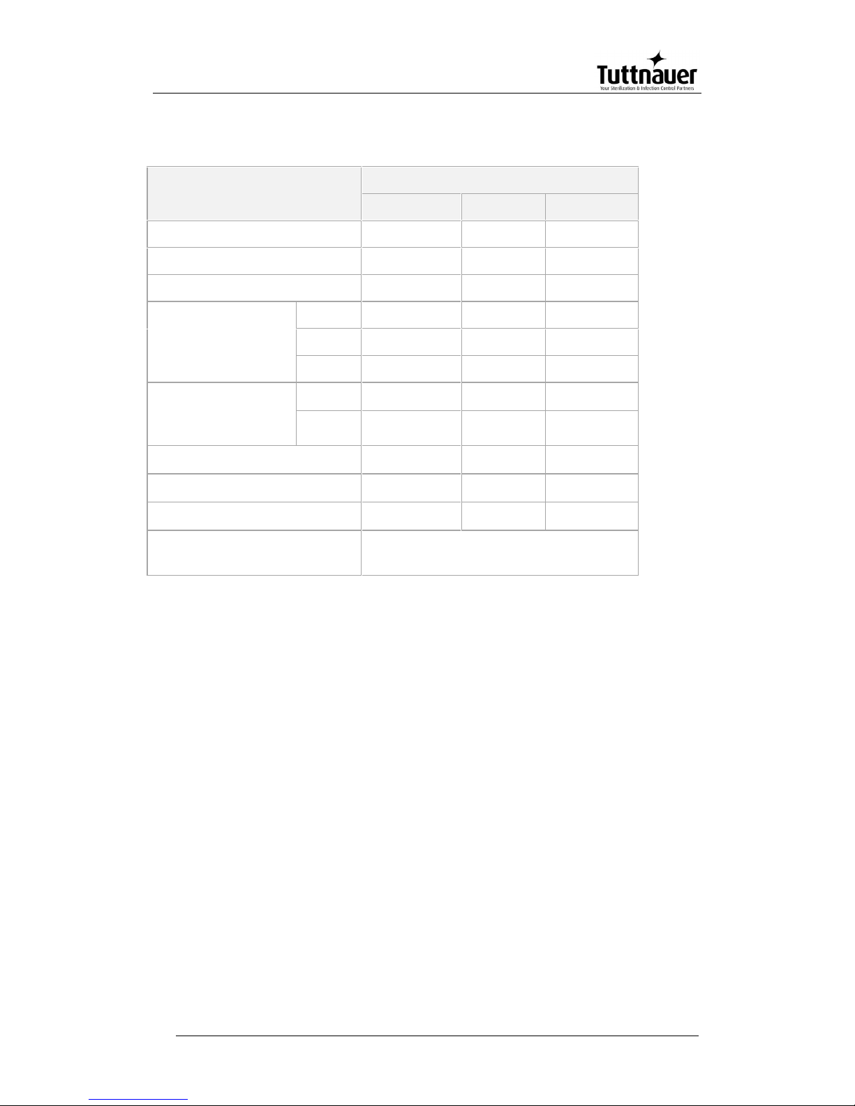
4.5 Specifications
Properties
Model
3840
3850
3870
Chamber diameter
380
380
380
Chamber depth
400
500
690
Chamber volume
52 liters.
65 liters.
85 liters.
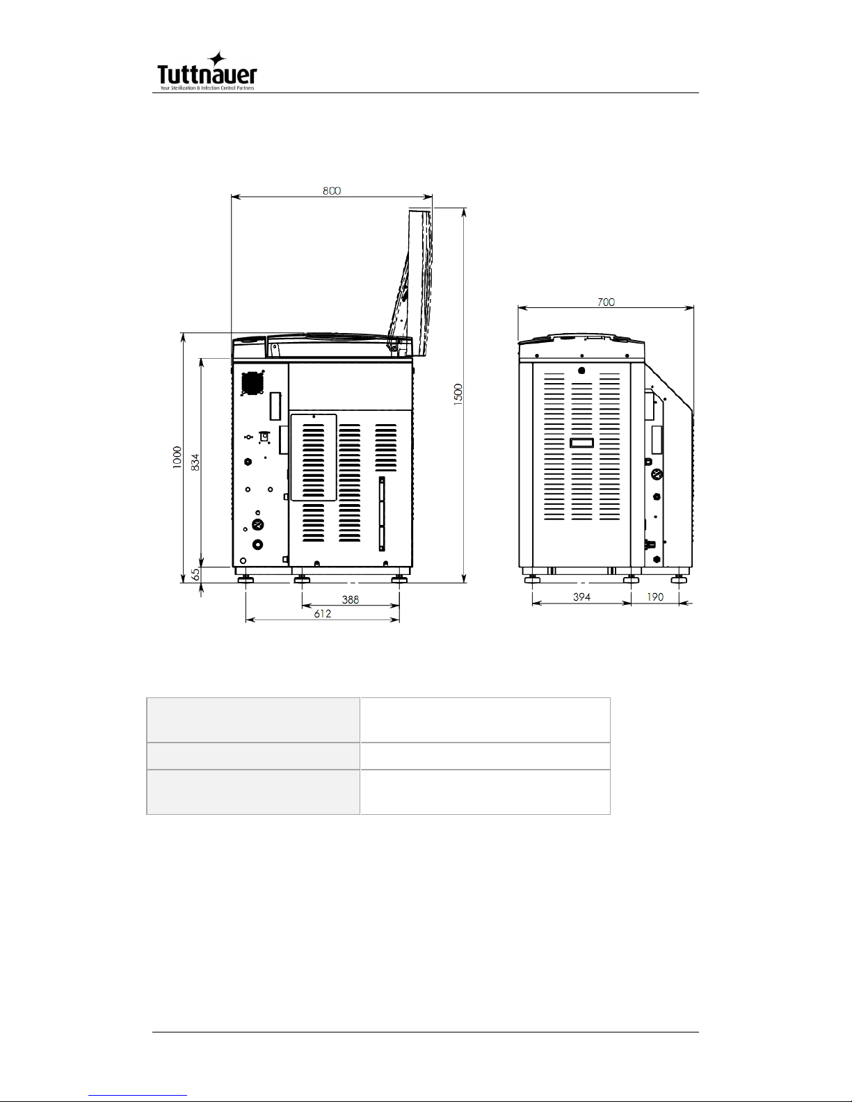
Overall dimensions
Height
1000
1000
1000
Width
730
730
730
Length
700
700
700
Maximum
dimensions
(door open)
Width
800
800
800
Length
1500
1500
1500
Net weight (kg)
105kg
108kg
113kg
Shipping volume
0.9 m3
0.9 m3
0.9 m3
Shipping weight
133kg
136kg
141kg
Max. Allowable Working
pressure (MAWP)
2.8 bar (40 psi)
Page 20
Page 18
4.6 Overall Dimensions
4.7 Construction
Chamber and door
material
Stainless steel
Outer Cabinet
Stainless Steel
Chamber insulation
Fiberglass with reinforced
material
Page 21
Page 19
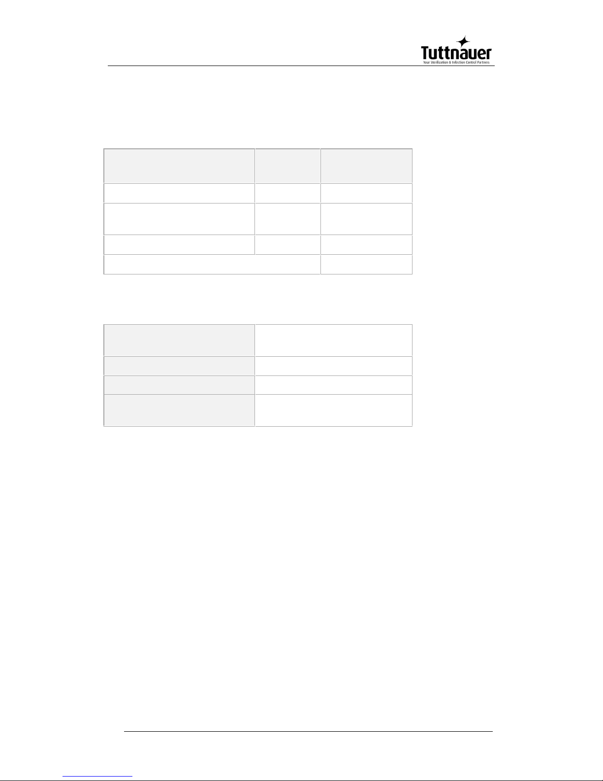
4.8 Utilities
4.8.1 Electrical utility
Power
Switch
box
Recommended
Circuit Breaker
208-220V (3 Ph + Earthing)
No
20A
380-400V(3 Ph + Neutral +
Earthing)
No
16A
230V 1ph
yes
32A
Frequency
50/60Hz
4.8.2 Other Utilities
Compressed Air
(ELVCPVG-D only)
1/2" 3-4 Bar (44-58 psi)
Tap water
1/2", 2-3 Bar (29-44 psi)
Mineral free water
1/2", 2-3 Bar (29-44 psi)
Drain
2" Minimum Withstanding
temp. of 80°C (176°F)
Attention:
A switch or circuit-breaker must be included in the building installation.
This switch or circuit-breaker shall be in close proximity to the
equipment, within easy reach of the operator; and marked as the
disconnecting device for the equipment.
The electrical net must be protected with a current leakage safety
relay.
The electrical network must comply with local rules or regulations.
Verify that there is an easy access to the main power switch, to the
water cut-off valve and to the current leakage safety relay.
Make sure while placing the autoclave, to leave space around the
machine, to give the technician access to service the machine.
All water connections to autoclave must be performed through "BACK
FLOW PREVENTION SYSTEM" only, as per IEC 61770.
Page 22
Page 20
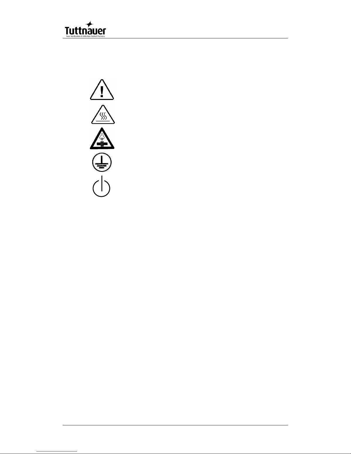
4.9 Symbol Description
Caution! Consult accompanying documents
Caution! Hot surface.
Caution! Hot steam.
Protective earth (Ground)
On-Off
Page 23
Page 21
5. Description of the Control System.
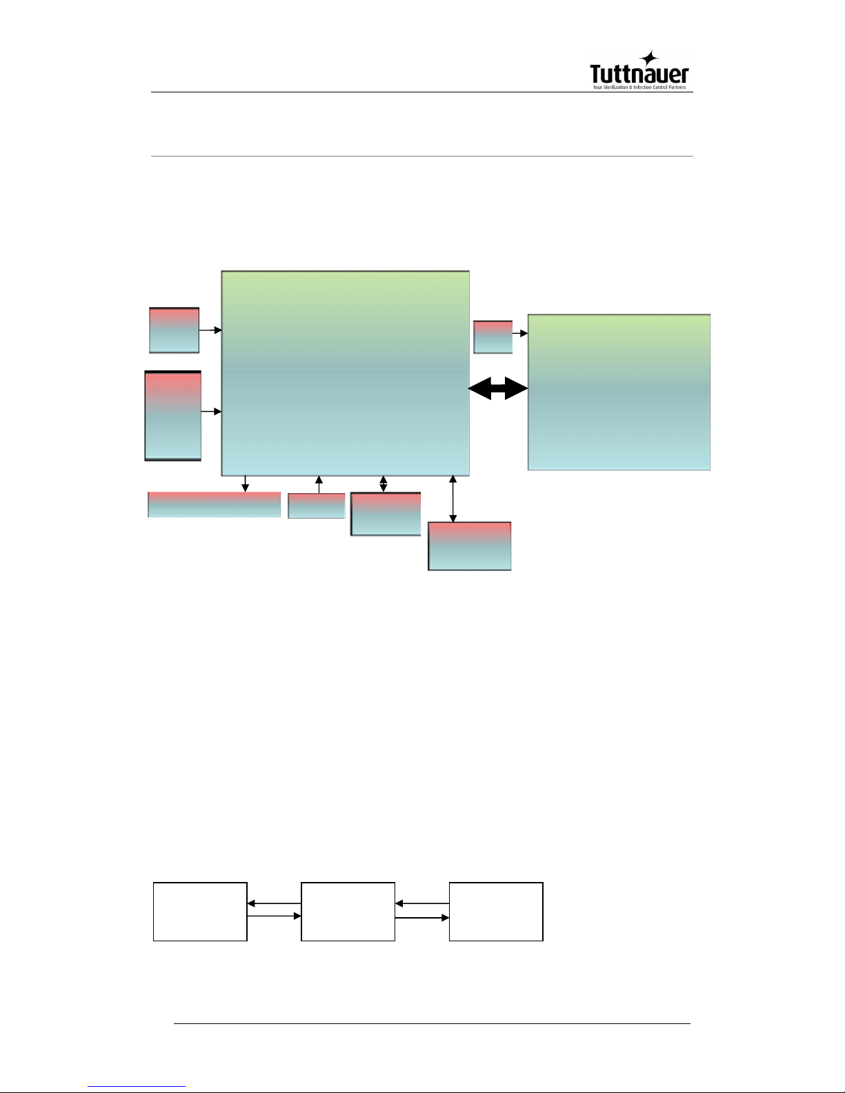
5.1 Hardware Control System Components: Block
Diagram
5.2 Application System Architecture
The system is divided into three main sections (dll)
1. GUI – holds all the Human Machine interface including the main
application screen and all the configuration screens which enable the
user to handle the machine.
2. Logic – holds all the application logic for running the machine.
3. Utilities – Holds general functionality which is used by the logic section
and the GUI section e.g: converting function for displaying different
pressure or temperature units type, languages etc.
Main board
- CPU +memory- Backup
power input
-MCIMX27LVOP4A+MC13783VK5
- R.T.C (including Battery)
M41T81SM6E
- Memory card expansion
MT46H32M16LFBF-
6:B+EPM570F256C5+S71WS256P
Ethernet
Am79C874
I/O Board
CPU- STM32F103R6T6
-24 Digital Outputs
-2 Analog outputs
-9 Digital inputs
-4 Analog Inputs 4-20mA
-6 Analog inputs Temp pt100
-3 Inputs water level
Keypad
Graphic Display 3.5"
USB Memory
socket
ISP1504ABS
24/12
VDC
Input
COM1
(RS232)
MAX323
2CSE+
Printer
24/12
VDC
GUI
LOGIC
UTILITY
Page 24
Page 22
Mapping of the software to the hardware – see Software Development
Plan.
The Hardware architecture is based on Freescale i.MX27 PDK
Evaluation Board.
5.3 Interfaces to Users
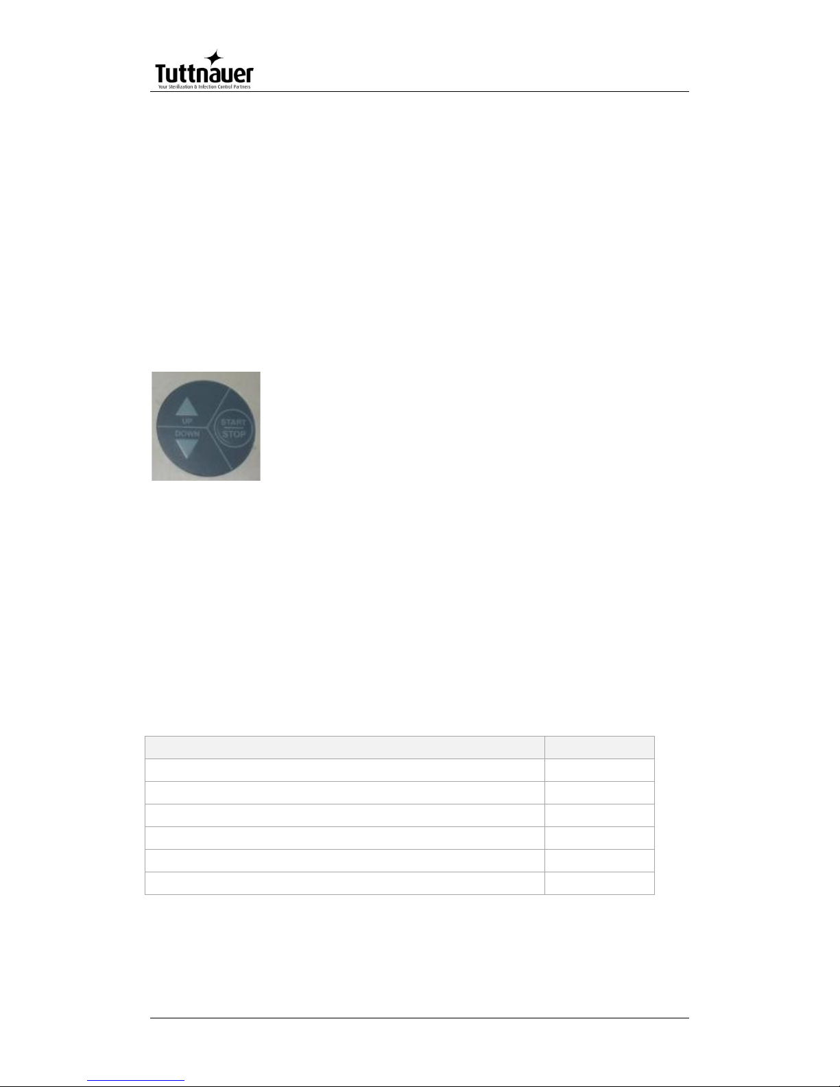
Keypad: The keypad has three push buttons:
o Down key
o Up key
o Start/stop key
Display: The control system has a graphical display
USB socket:
The USB socket is intended to load cycles' history from flash a
memory (disk on key). The received file is in txt format that can be
loaded onto a PC.
5.4 Inputs and Outputs
Analog inputs
Analog inputs
JP
Drain temperature
J5
Chamber temperature
J2
Bio hazard filter temperature
J6
Ref temperature
J3
Jacket temperature
J4
Chamber pressure
J7/1
Page 25
Page 23
Digital inputs
Digital Inputs
JP
Door closed
J12/1
Door unlocked
J12/6
Door locked
J12/8
Digital outputs
Digital Outputs
JP
Steam to jacket
J13/8
Vacuum pump
J13/12
Exhaust to bio
J13/14
Main exhaust
J13/16
Atmospheric air valve
J14/2
Compressed air to chamber
J14/4
Slow exhaust
J14/6
Fast exhaust
J14/8
Vacuum valve
J14/10
Cool Drain
J14/12
Steam to chamber
J14/14
Cooling water
J14/16
Compressed air to jacket
J15/2
Close door
J15/4
Open door
J15/6
Air to door
J15/14
Actuators
The control system operates electrical valves (solenoids), Electric
cylinder motors, pneumatic cylinders, electric pumps, heaters.
On / off switch
A Rocker Switch 250V AC, 16A
Page 26
Page 24
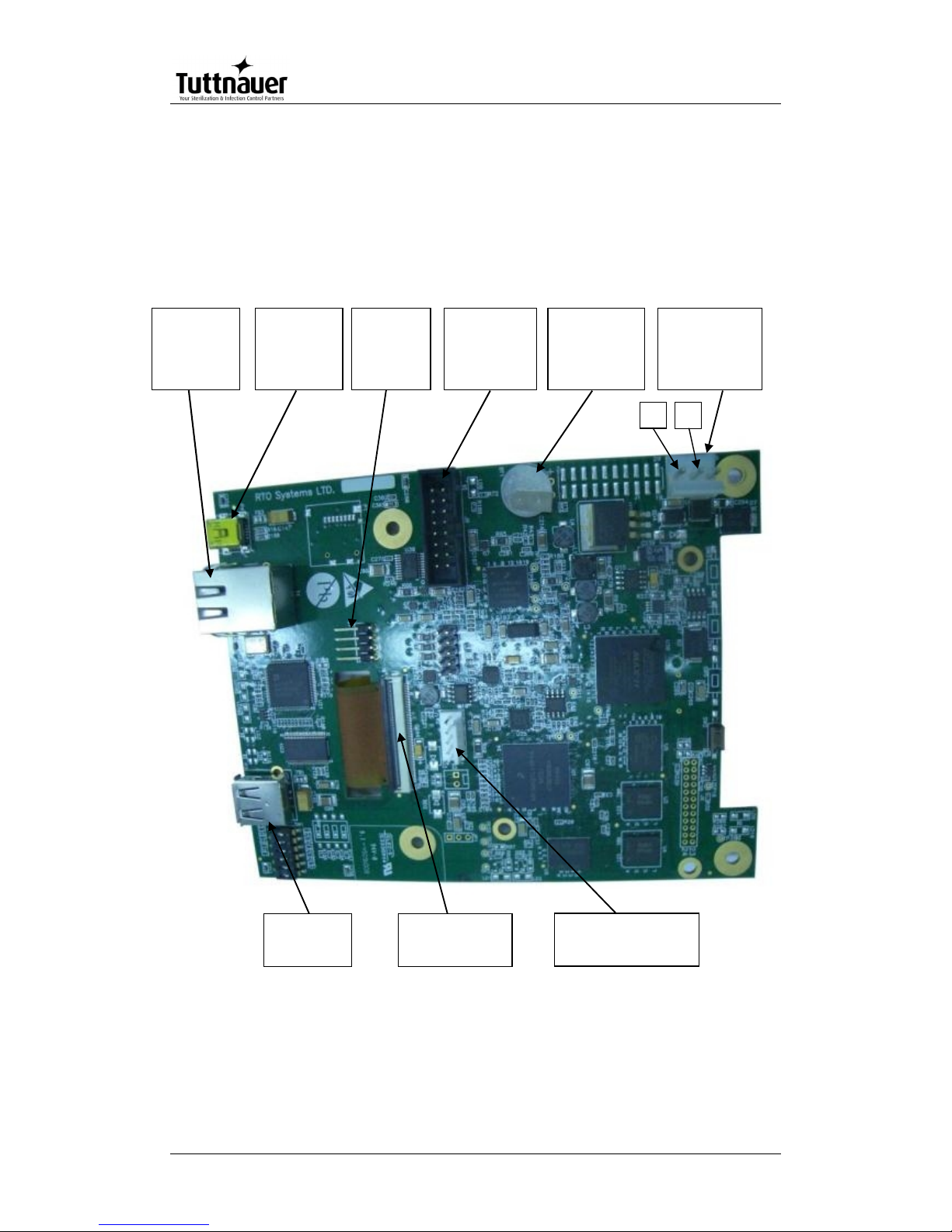
5.5 Hardware Control System components
The hardware is consisted of cards: MAIN and IO
Main card
Operating system (MAIN card)
The Operating system is Microsoft Windows CE version 6. The code to
the Operating system is supplied by Microsoft. The connection code
between the Operating system and the hardware components (BST –
Power Supply
Connector
(24V DC)
Connector to
printer
+
Ethernet
Connector
SD
Not in use
USB
Connector
-
Connector
to IO Board
Connector to
LCD display
Connector
to Keypad
Lithium coin
battery T.H
orizontal 3V
48mAh
J5
BT1
J8
J4
P2
P4
T1
P3
J3
Page 27
Page 25
Board Support Package) is supplied by FreeScale. Minimum suitability
for this "Tuttnauer" project is performed in this code.
Development tools (MAIN card)
The software develop environment is on Microsoft Visual Studio 2005
that includes the Microsoft Platform Builder for Windows CE 6.0. The
specific Tuttnauer system application is written in C Sharp.net on
Microsoft Compact Framework.net
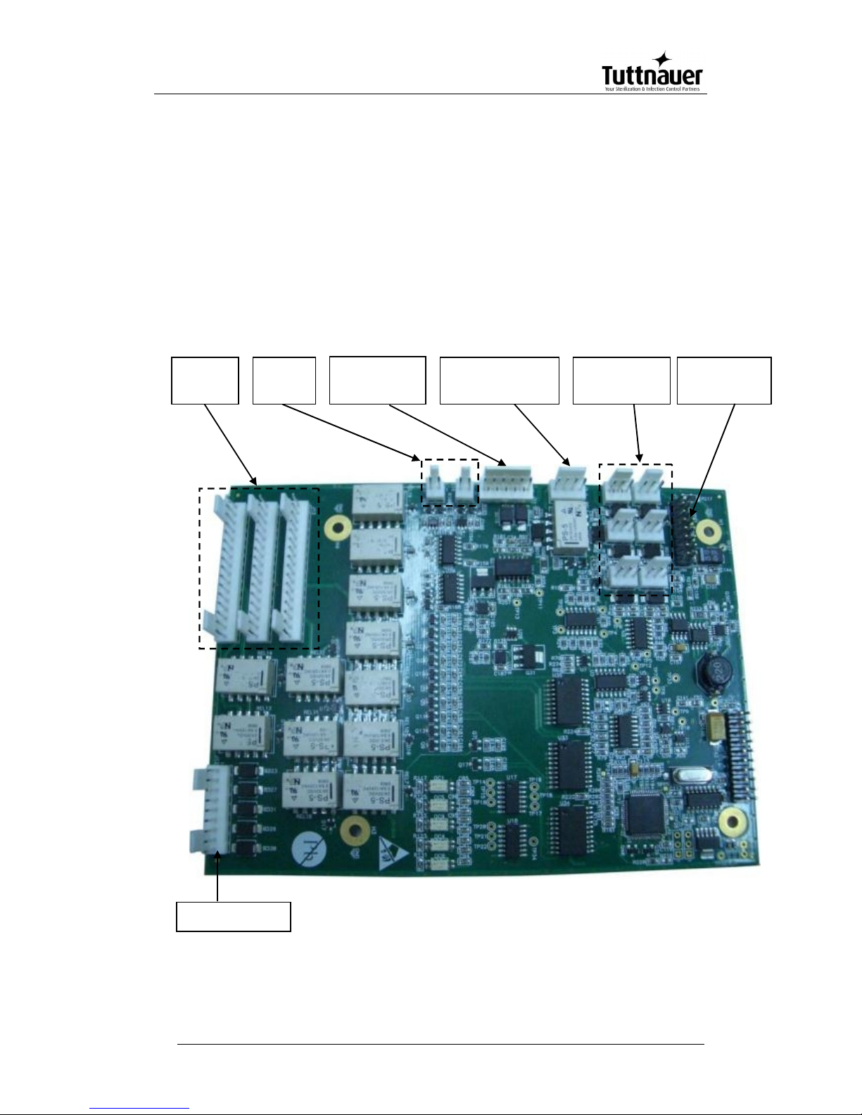
IO Card
Analog inputs
(PT-100)
Analog inputs
-
20mA)
Analog inputs
electrodes
J
J
J6
J3
J4
J1
J7
J11
J16
J17
J13
J15
J14
Connection to
MAIN Board
Analog
outputs
Digital
outputs
Digital Inputs
J12
Page 28

Page 26
IO card is an independent card. It checks the card by a method of a
continuous scan of all the ports, saving the data in the memory and
transporting this data according to the request in the communication
channel RS-232 to the personally adapted protocol.
At the end of the check process of the digital and analog ports, the
communication channel is checked, in case of receiving a request, the
request is checked and if the request is legitimate it will be taken care
of.
The IO card is controlled by the MAIN card. Only when requests are
received from the MAIN, the requests will be checked and performed.
The IO card will perform an electrical restart of the systems (IO card) if
it does not receive requests within 5 seconds. In the next request
received from the MAIN, the IO card will indicate to the requester of IO
card systems restart.
The "brain" in the IO card runs on microcontroller type:
STM32F103R6T6.
The Microcontroller is an electrical Integrated circuit with an actualized
complete system (SoC) including a processing unit, external interfaces,
memory, etc.
The Microcontroller is constructed of a number of main components:
Central processing unit – the main component in the microcontroller is
a central processing unit (CPU) This unit is in charge of receiving the
request (command) code from the memory, deciphering, receiving
variable data from the memories and performing the command.
Memory – divided into 2 sections.
• software memory – in this memory the software that samples the IO
card and request (command) from the user are saved. As this memory
is a flash memory it is possible to burn the code many times (efficient
to the development stage).
• information memory – in this memory the data and other variables
values are saved. This memory is not flash memory, but is RAM
memory.
Digital / Analog ports (in/out) – through them the microcontroller can
receive data of digital/analog signs from the system, save them and
pass them on respectively to the user request.
Ports (in / out) to the communication – in the IO card there is a UART
component. This component enables communication with the MAIN
card through the RS-232 in suitable protocol.
MAIN and IO cards :communication protocol between IO board to Main
Board
Page 29

Page 27
Communication protocol between IO to Main boards is described
below.
The communication manged by the Main board (master), the IO
functions as slave.
There are six communication functions.
The communication functions (to read or write) identified by number.
The communication functions listed below:
01 Read – command to IO send all the information of digital analog
inputs.
02 Write – Command to IO to activate analog and digital outputs.
03 Read version – IO software version to verify the version.
04 N.A.
05 Read number that identifies the ID of IO board and the software
version.
06 Write (only at the first time) to IO his ID and software number.
First Byte (Byte 1).
The first byte identifies ID functionality request. It can be one of the
numbers in a paragraph.
The second byte will present the data size if the main board asks to
write information to the IO. If the request is to read this byte will be 00.
The number of the request. This number is increased from 00-ff.
Check sum of the package – to prevent mail functionality of the board if
there is interference in communication.
The information package transfer. The information contains number of
the input or output and data for/from each I/O.
Bytes identify number of input or output followed by two bytes
containing the data of the input or outputs.
Last byte contains a check sum of the entire package that is
transferred. This is to verify that the information is not corrupted.
Example:
The main board sends:
01;00;0003;0004;
01 Ask to Read inputs.
00 not transfer information.
0003 Request number 3
0004 Checksum to verify the request
Page 30
Page 28
6. Checking and Changing Parameters
and Other Data
Bacsoft control panel allows changing parameters of the cycle and of
the system, exporting various data to, and importing from, a USB
device or to the printer, and some other options.
Cycle parameters are changeable for Custom programs only (see
Duplicate cycles), with the exception of the Temperature sensors,
Displayed inputs, and Dry Time.
6.1 Browsing through the menus
Now you will learn how to browse through the folders. When you read
the Directories and subdirectories chapter with links to specific menus,
you will need to know how to browse through the folders using the
autoclave control panel. Below is the instruction.
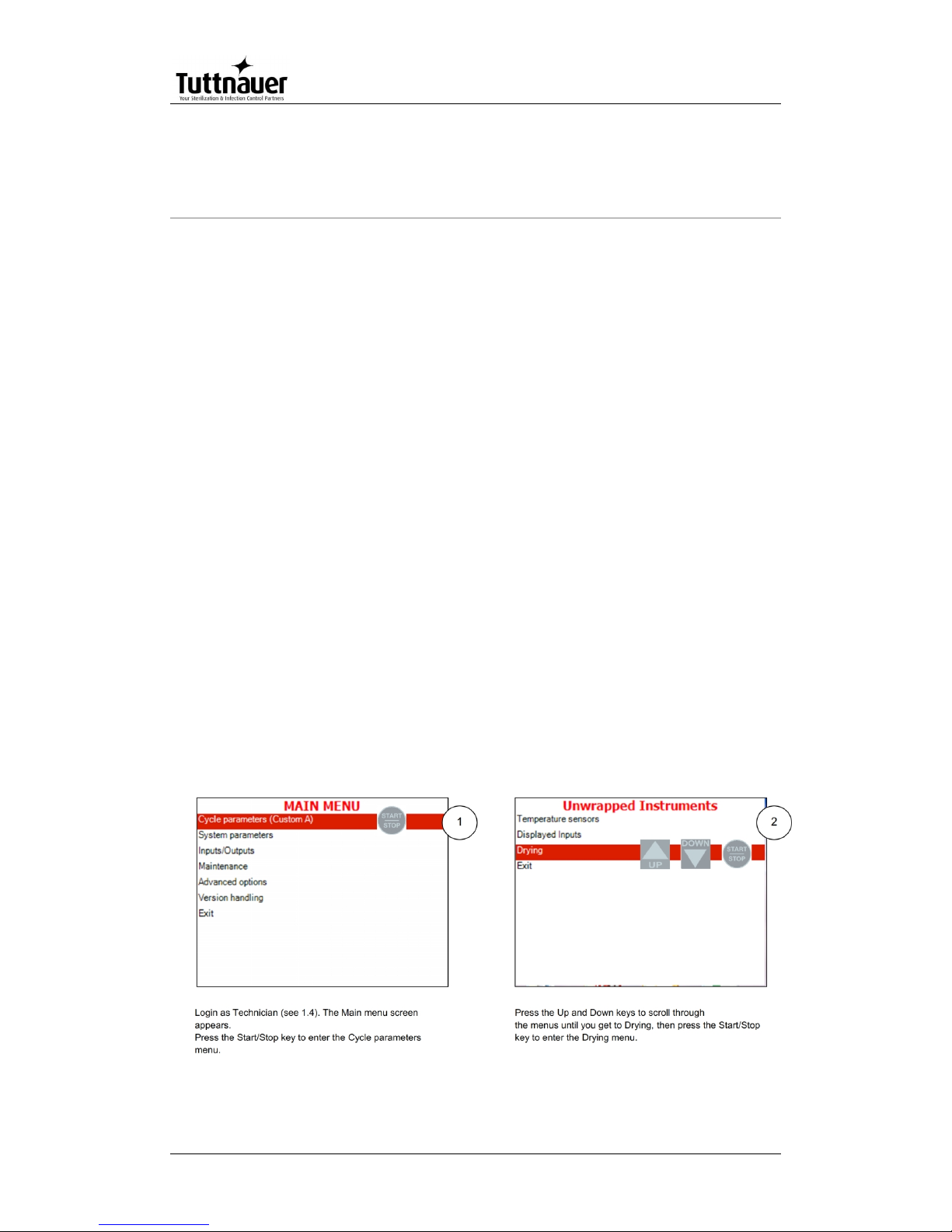
Login as Technician (see 6.4). The Main menu screen appears. To
browse through the menus:
1. Press the Up and Down keys to scroll through the menus.
2. Press the Start/Stop key to enter the next screen (i.e. to get one level
down).
3. Repeat steps 1 and 2 to enter the next screen until you get to required
screen.
Below are the example screens for the following menu: Cycle
Parameters\ Drying\ Dry Time:
Page 31

Page 29
Note: To exit every screen and to return to the previous screen (to get one
level up):
move the cursor to Exit by pressing the UP or DOWN keys and then
press the Start/Stop key.
- or-
press the UP and DOWN keys simultaneously.
In the next chapter you will see how to change the required parameter
as desired.
6.2 Changing a Parameter
You have browsed through the menus and reached the parameter
changing screen as explained above. Now you can change the
required parameter as desired. To do so:
1. Enter the required value as follows:
Press the Up and Down keys to change the value of the digit.
Press the Start/Stop key to move the cursor to the next digit to the left.
2. When finished, press the Start/Stop key repeatedly until you move the
cursor to Set.
3. Press the Up or Down key to confirm the new value and to exit the
parameter changing screen.
Below is the typical parameter changing screen:
Page 32

Page 30
Note: Please note the maximum and minimum values for this parameter
shown on the screen. Your value must be within these boundaries.
Below is the example of changing the Dry time parameter on the
screen used in the previous section:
Page 33

Page 31
Note: To exit every screen and to return to the previous screen:
move the cursor to Exit by pressing the UP or DOWN keys and then
press the Start/Stop key
- or-
press the UP and DOWN keys simultaneously
6.3 Quick options screen
When the autoclave is on and no cycle is running, press Up and Down
keys simultaneously to enter the Quick options screen. Most of the
options require login, and their availability depends on user authority
(user, or technician). Login command is the last line on this screen.
Quick options are options available without login.
Page 34

Page 32
Below you can find instructions how to login and enter the Main menu.
Section 7.1 above explains how to browse through the menus; section
7.2 explains how to change a parameter.
Below is the explanation of the Quick Options.
6.3.1 Export to USB
his subdirectory allows you to export settings and cycles history to the
USB device.
1. Insert the USB device into the USB socket.
2. Enter the Export to USB screen.
To export settings:
a. Choose Export all settings to USB device.
b. Press the Start/Stop key. The following screen will appear:
Page 35

Page 33
To export cycles history:
c. Choose All cycles history, 10 Cycles, or 50 Cycles.
d. Press the Start/Stop key. The following screen will appear:
3. Remove the USB device from the USB Socket.
6.3.2 Print cycles
This subdirectory allows printing out cycle reports for a number of
previous cycles (See the Printer handling section of the Operation and
maintenance manual).
1. Enter the Print Cycles screen.
Page 36

Page 34
1. Choose Print last cycle, Print last 5 cycles, or Print last 10 cycles.
2. Press the Start/Stop key. The cycle reports will be printed.
6.3.3 Version Information
This directory allows viewing information of the current, factory default,
and previous software versions.
1. Enter the Version information screen.
6.3.4 Start cycle by clock
This subdirectory enables the operator to start the cycle at the time set
by this paramter.
1. Enter the Start cycle by clock screen. The following screen will appear:
Serial
number
Software
version
Page 37

Page 35
On the Start cycle by clock screen, the time is displayed in the form
“HH:MM”. The hour range is 24 hours (i.e. from "0" to "24").
Setting the time to start the cycle
1. Move the cursor to the Time field.
2. Set the required time.
Enabling the Start Cycle by Clock
1. Set the starting time.
2. Move the cursor to Enabled. Press Up or Down key to enable starting
cycle by clock.
1. Exit the Enabling the Start Cycle by Clock. The start cycle by clock icon
appears on the display:
Page 38

Page 36
Disabling the START CYCLE BY CLOCK
2. On the Start Cycle by Clock screen, move the cursor to Disabled.
Press Up or Down key to disable Starting cycle by clock.
3. Exit the Enabling the Start Cycle by Clock.
6.3.5 Set date and time
This subdirectory enables the operator to set date and time.
On the Set date and time screen, the time is displayed in the upper row
in the form "HH:MM:SS". The hour range is 24 hour (i.e. from "0" to
"24"). The date is displayed in the lower row in the form "DD: MMM:
YYYY".
1. Set time and date
2. Exit the Set date and time screen. The following screen will appear:
Page 39

Page 37
Caution!
After setting time and date, turn the autoclave off and then on
again.
6.4 Logging in and entering the Main menu
Below you can find instructions how to login and enter the Main menu.
Section 7.1 above explains how to browse through the menus, section
7.2 explains how to change a parameter.
When the autoclave is on and no cycle is running, press the up and
down keys simultaneously to enter the Quick Options screen (see 6.3).
On this screen you can either proceed to login (see below) or choose
one of the quick options available without login. To login as technician:
1. On the Quick Options screen, choose login.
Select user screen appears.
Page 40

Page 38
2. Choose Technician, then press the Start/Stop key to enter. The
following screen will appear:
0000 is displayed on the screen with the cursor flashing on the right
digit.
Set the code to 0321. You will get to the Main menu.
Below is the list and the explanation of the options available on the
Main Menu.
6.5 Directories and subdirectories
Bacsoft control panel provides an interface that consists of control
screens available through an easy scrollable menu tree.
Page 41

Page 39
To learn how to scroll through the menus, change the parameters,
and perform some other functions using our three-button keypad,
see 6.1 and6.2.
The following table lists the options that the technician may perform.
Directory
Subdirectory
Cycle Parameters
1
Temperature sensors
Displayed inputs
Purge (generator models only)
Drying
Create Pulse
Keep Heat
For custom programs only
Heating
Sterilization
Cooling (“C” models only)
Exhaust
Drying
Ending
Global
System Parameters
Print Rate All
Print Rate Sterilization
Screen Saver
Pressure calibration high
Pressure calibration low
Temperature calibration high
Temperature calibration low
Cycle Print Gap
Inputs/Outputs
View digital inputs state
View digital outputs state
Test digital outputs
1
See cycle parameters in more detail in Cycle Parameters.
Page 42

Page 40
Directory
Subdirectory
View analog inputs state
Analog inputs calibration
Maintenance
Export gain offset to USB
Import gain and offset from USB
Reset atmospheric pressure
Test RTC
Printer test
Print all gain and offset
Advanced Options
Enable cycles
Set Language
Set temperature units
Set pressure units
Duplicate cycles
Delete custom cycles
Set external IP address
Version Handling
Import application from USB
Import all settings from USB device
Import application and setting from USB
Return to factory default settings
The following chapter explains meaning and usage of the control
screens.
Below is the typical parameter changing screen:
Page 43

Page 41
6.6 System Parameters
This menu is listing the system parameters that are the same for all
cycles. Browse to the following folder:
Main menu\System parameters
You will see the following screen:
Below is the instruction for changing the system parameters.
6.6.1 Print Rate All
In this menu you can define the time interval for printing out the cycle
status, for all the stages except sterilization: The default is 3 minutes.
See the Printer handling section of the Operation and maintenance
manual.
Page 44

Page 42
Browse to the following folder:
System parameters\Print Rate All
Change the parameter as desired
6.6.2 Print Rate Sterilization
In this menu you can define the time interval for printing out the cycle
status during the sterilization stage: The default is 1 minutes.
Browse to the following folder:
System parameters\Print Rate Sterilization
Change the parameter as desired
6.6.3 Screen Saver
In this menu you can define the screensaver delay time, i. e. how long
the keyboard will be untouched before the screensaver activates.
Browse to the following folder:
System parameters\Screen Saver
Change the parameter as desired.
6.6.4 Pressure calibration high
In this menu you can define the high calibration point for pressure.
Browse to the following folder:
System parameters\Pressure calibration high
Change the parameter as desired.
6.6.5 Pressure calibration low
In this menu you can define the low calibration point for pressure.
Browse to the following folder:
System parameters\Pressure calibration low
Change the parameter as desired.
6.6.6 Temperature calibration high
In this menu you can define the high calibration point for temperature.
Browse to the following folder:
System parameters\Temperature calibration high
Change the parameter as desired
Page 45

Page 43
6.6.7 Temperature calibration low
In this menu you can define the low calibration point for temperature..
Browse to the following folder:
System parameters\Temperature calibration low
Change the parameter as desired
6.6.8 Cycle Print Gap
This parameter defines the time interval between printing the current
values of the cycle (See the printer output section).
Browse to the following folder:
System parameters\Cycle Print Gap
Change the parameter as desired
6.7 Inputs/Outputs
It is important for the technician to control the system down to the level
of specific inputs and outputs. Viewing the outputs state at specific
stages of the cycle helps you diagnose the malfunctions. You can also
test and calibrate inputs and outputs.
Below is the typical screen for viewing/testing the inputs/outputs.
Below is the instruction for working with inputs/ outputs.
6.7.1 View digital inputs state
In this menu you can view, at any stage, which digital inputs are being
controlled at the moment.
Page 46

Page 44
Browse to the following folder:
Inputs/Outputs\View digital inputs state
6.7.2 View digital outputs state
In this menu you can view, at any stage, which digital outputs are being
controlled at the moment.
Browse) to the following folder:
Inputs/Outputs\View digital outputs state
6.7.3 Test digital outputs
In this menu you can view the normal function of all the autoclave
elements: valves, heating elements, pumps, etc.
Browse to the following folder:
Inputs/Outputs\Test digital outputs
Note: on the screen that appears, scroll down for more outputs.
Check the checkboxes of the outputs you want to test.
6.7.4 View analog inputs state
In this menu you can view, at any stage, the values of the analog
inputs at the moment.
Browse to the following folder:
Inputs/Outputs\View analog inputs state
6.7.5 Analog inputs calibration
In this menu you can calibrate water level, mineral water level,
pressure, and temperature sensors of the autoclave chamber.
1. Browse to the following folder:
Inputs/Outputs\Analog inputs calibration
The following screen will appear:
Page 47

Page 45
2. Press Up or down key to choose the input to calibrate and press
Start/Stop.
The following screen will appear:
See below description of each option.
6.7.6 Auto calibrate
Bacsoft software has an option for automatic calibration using the
PT100 simulator.
On the calibration options screen, choose Auto calibrate.
The following screen will appear:
Page 48

Page 46
6.7.7 Calibrate analog input
This menu allows calibrating analog inputs manually.
1. On the calibration options screen, choose Calibrate analog input.
The following screen will appear:
2. In the Actual field, change the high and low values of the input as
desired.
6.7.8 Set gain and offset
1. On the calibration options screen, choose Set gain and offset.
2. The following screen will appear:
Page 49

Page 47
Change gain and offset as desired.
6.7.9 Restore last calibration
There is an option to restore the gain and offset values set at previous
calibration.
1. On the calibration options screen, choose Restore last calibration.
The following screen will appear:
2. Using the up and down keys, move your cursor to confirm and press
Start/Stop.
The following screen will appear:
Page 50

Page 48
6.7.10 Restore default calibration
There is an option to restore the default (factory) gain and offset values
1. On the calibration options screen, choose Restore last calibration.
The following screen will appear:
2. Using the up and down keys, move your cursor to confirm and press
Start/Stop.
The following screen will appear:
Page 51

Page 49
6.8 Maintenance
Maintenance procedures provided by Bacsoft software allow you
additional tests and USB input/output options.
Browse to the following folder:
Main menu\Maintenance
You will see the following screen listing the maintenance options:
Below is the instruction for autoclave’s maintenance menu.
6.8.1 Export gain offset to USB
In this menu you can export to USB the gain and offset you have got as
a result of calibration.
Browse to the following folder:
Maintenance\ Export gain offset to USB
Page 52

Page 50
6.8.2 Import gain and offset from USB
In this menu you can import from the USB the gain and offset
documents you have got as a result of calibration to the autoclave.
Browse to the following folder:
Maintenance\Import gain and offset from USB
Press Start/Stop. The following screen will appear:
6.8.3 Reset atmospheric pressure
In this menu you can reset the atmospheric pressure value. To do so:
1. Browse to the following folder:
Maintenance\Reset atmospheric pressure
The following screen will appear:
Page 53

Page 51
2. Leave the door open for 2 minutes at least. Ambient temperature
should be less than 45°C.
Note: Please reset the atmospheric pressure when you install the autoclave
for the first time, and each time you relocate or calibrate the autoclave.
6.8.4 Test RTC
In this menu you can check the two clocks. The two clocks work during
the interval set by the Test RTC parameter, and the results are
displayed. If the results are different for more than 2 seconds, one of
the clocks is faulty.
1. Browse to the following folder:
Maintenance\Test RTC
The following screen will appear:
2. Set the time interval as desired. Then move the cursor to start and
press Start/Stop.
At the end of the test, the following screen will appear:
Page 54

Page 52
3. Using the Up and Down keys, move the cursor to Exit.
6.8.5 Printer test
In this menu you can check the normal function of the printer. The
printer will print the list of errors.
Browse to the following folder:
Maintenance\Printer test
The following screen will appear to confirm that the test has been done.
See the printout shown in the Printer handling chapter of the user
manual.
6.8.6 Print all gain and offset
In this menu you can print all the gain and offset for all the pressures
and temperatures in the autoclave (Chamber Temperature, Chamber
Pressure, Chamber Water Level, Mineral Free Water Level.
Page 55

Page 53
Browse to the following folder:
Maintenance\Print all gain and offset
See below the example of a printout:
Chamber Temperature
G:000.0385;O:-008.0976
Chamber Pressure
G:000.1238;O:-098.5985
Chamber Water Level
G:001.0000;O:000.0000
Mineral Free Water Level
G:001.0000;O:000.0000
6.9 Advanced Options
Advanced options menu gives you even more possibilities, including
interface customization, changing the settings, enabling, adding and
deleting cycles, etc.
Browse to the following folder:
Main menu\Advanced options
You will see the following screen listing the Advanced options:
Page 56

Page 54
Below is the instruction for the Advanced options menu.
6.9.1 Enable cycles
In this menu you can enable only the cycles you want to use. The
cycles you do not want to use will not appear on the screen.
Browse to the following folder:
Advanced Options\Enable cycles
Move cursor to the cycles you want to enable/disable and
check/unchek them as desired.
6.9.2 Set Language
In this menu you can choose the language for all the interface screens:
menus, cycle information, system messages.
1. Browse to the following folder:
Advanced Options\Set Language
Page 57

Page 55
Note: There are more languages than you see on the screen above. Just
scroll down to see more.
2. Move the cursor to the desired language and check it. The following
screen will appear:
The machine will be restarted and the main screen (current cycle) will
appear in the chosen language.
6.9.3 Set temperature units
In this menu you can set the temperature units (Celsius or Fahrenheit)
for screens and printouts.
Browse to the following folder:
Advanced Options\Set temperature units
Change the parameter as desired
Page 58

Page 56
6.9.4 Set pressure units
In this menu you can you can set the pressure units (kPa, Psia, Psig,
BarA, BarG) for screens and printouts.
Browse to the following folder:
Advanced Options\Set pressure units
Change the parameter as desired
6.9.5 Duplicate cycles
In this menu you can create a copy of one of the cycles with all its
parameters (the parameters can be changed then). You can give any
name to the new custom cycle.
Browse to the following folder:
Advanced Options\Duplicate cycles
1. Using the Up and Down keys, move the cursor to the cycle you want to
duplicate, then press Start/Stop to select the cycle. A custom program
has been created with the same settings. You will be able to change
the settings later. The following screen will appear:
Page 59

Page 57
1. Give the name to your cycle.
2. Exit the menus until you get to the main screen.
3. Select your newly created program.
Note: you can select the program only when the autoclave door is open.
4. Login again as Technician (see 6.4).
5. In the main menu, select Cycle parameters and enter the Cycle
Parameters screen.
The following screen will appear:
Page 60

Page 58
Now you can alter the cycle parameters as desired.
6.9.6 Delete custom cycles
In this menu you can delete the custom cycles that were created.
Browse to the following folder:
Advanced Options\Delete custom cycles
1. Move the cursor to the cycle you wish to delete. Press Start/Stop key to
select/deselect the cycles.
2. Move the cursor to Delete selected cycles and press Start/Stop key to
delete.
The following screen will appear:
The selected custom cycle is now deleted.
Page 61

Page 59
6.9.7 Set external IP address
This option allows to set specific external IP address to be used for
remote RCPR connection.
Browse to the following folder:
Advanced Options\Set external IP address
Set the External IP Address as desired.
6.10 Version handling
The version handling menu provides tools to import, export, and
restore the autoclave software.
Browse to the following folder:
Main menu\Version Handling
You will see the following screen listing the version handling options:
Below is the instruction for version handling.
6.10.1 Import application from USB
In this menu you can replace the autoclave software with the
application software from the USB device to the autoclave.
1. Browse to the following folder:
Version handling\Import application from USB
The system will prompt you to confirm import
2. Move the cursor to Confirm and press Start/Stop.
The application will be imported from the USB device.
Page 62

Page 60
6.10.2 Import all settings from USB device
In this menu you can import the autoclave’s individual settings from the
USB device. The settings include all the changeable parameters of the
cycle and the system.
1. Browse to the following folder:
Version handling\Import all settings from USB device
The following screen will appear:
On this screen, you will see the model name and parameters
checksum of the settings saved on the USB device.
2. Move the cursor to Confirm and press Start/Stop.
The following screen will appear:
3. There is an option to keep the old serial number or calibration data
while exporting all the rest from USB. Check/ uncheck respective
checkboxes as desired.
Page 63

Page 61
All the autoclave settings will be imported from the USB device with the
exception of the screen above.
6.10.3 Import application and setting from USB
In this menu you can replace both the application software and the
parameters of the autoclave with the software and parameters from the
USB device.
4. Browse to the following folder:
Version handling\Import application and setting from USB
5. Move the cursor to Confirm and press Start/Stop.
6.10.4 Return to factory default settings
In this menu you can restore the default values of all the changeable
parameters of the cycle and the system. Default settings are those your
autoclave had when it left the factory.
1. Browse to the following folder:
Version handling\Return to factory default settings
2. Move the cursor to Confirm and press Start/Stop. The default factory
settings will be restored.
6.11 Cycle parameters
The Cycle parameters menu includes parameters of a specific
sterilization program (cycle). Browse to the following folder:
Main menu\Cycle parameters
You will see the following screen listing the cycle parameters:
Page 64

Page 62
Note: For all the standard sterilization cycles, and for Bowie and Dick test, the
only changeable cycle parameter is dry time (you will not see other
parameters on your screen). For the custom cycles created by
duplication, and for the Warm Up cycle, all the options listed in table
below are changeable. Operator is not allowed to create custom
cycles; only authorized technician can do this.
Subdirectory
Property
Temperature sensors
Chamber Temperature
Displayed inputs
First
Second
Third
Purge (generator models only)
Purge time
Purge temperature
For custom programs only
Create
Puls
e
Pulse A Count
Pulse A Stay Time
Pulse A Low Pressure
Pulse A High Pressure
Pulse B Count
Pulse B Stay Time
Pulse B Low Pressure
Pulse B High Pressure
Keep Heat
Temperature 1 stay
Temperature 1 stay time
Temperature 2 stay
Temperature 2 stay time
Page 65

Page 63
Heating
Sterilization Temperature
Sterilization
Sterilization Temperature
Sterilization Time
For custom programs only
Cooling (“C”
mod
els
only)
Cool Mode
Cool End Temperature
Cool Exhaust Rate
Exhaust
Exhaust Mode
Drying
Dry Time
Dry Heat On 1
Dry Heat Off 1
Dry First Stage Time
Dry Heat On 2
Dry Heat Off 2
Add Dry Time
Ending
End Temperature
Global
FO Mode
Check RTC
Multiple Cycles
Multiple Cycles Gap
Jacket Temperature
The following chapters explain meaning and usage of the control
screens for the cycle parameters.
6.12 Temperature sensors
6.12.1 Temperature sensors \Chamber Temperature
In case a machine has a number of temperature sensors, there is an option to
assign every chamber temperature sensor to be one of the following:
main, reference, not in use,.
1. Browse to the following folder:
Cycle parameters\Temperature sensors\Chamber Temperature
The following screen will appear:
Page 66

Page 64
2. Using Up and Down keys, move the cursor around the screen and
check the desired radio buttons by pressing Start/Stop.
3. Using Up and Down keys, move the cursor to Save and press
Start/Stop.
6.13 Displayed inputs
This menu defines 2 (or 3, according to the cycle type) input values to
be shown on the display.
You can choose, for each of them: chamber temperature, chamber
pressure, chamber water level, and mineral free water level. Below is
the example of setting the first input.
1. Browse to the following folder:
Cycle parameters\Displayed inputs\First
The following screen will appear:
Using the Up and Down keys, choose first, second, or third.
2. The following screen will appear:
Page 67

Page 65
3. Using Up and Down keys, move the cursor to the desired radio button
and choose it by pressing Start/Stop.
6.14 Purge (generator models only)
There is an option to remove the air from the chamber before
sterilization. Saturated steam is introduced into the chamber and it
pushes the air out through a valve. Purge is usually used for Isothermal
cycle.
1. Browse to the following folder:
Cycle parameters\Purge
The following screen will appear:
2. Change the parameters as desired.
6.15 Create Pulse
This menu allows to set parameters for each pulse of the program (see
below).
Page 68

Page 66
6.15.1 Pulse A Count
This parameter defines how many times the pulse of each type (A, B)
is repeated. For example, if the Pulse count for pulse A (low) is 4, and
the Pulse count for pulse B (high) is also 4, the cycle will have the
following pulses: low-high-low-high-low-high-low-high.
1. Browse (to the following folder:
Cycle parameters\Create Pulse\Pulse A Count
Change the parameter as desired.
Note: Pulse A and B counts for standard programs equal one, with the
exception of Hollow load, Waste, and Bowie and Dick test (pre-vacuum
models only), whose pulse count equals four.
6.15.2 Pulse A Stay Time
This parameter defines the value of delay after the required pressure
for the pulse is reached.
1. Browse to the following folder:
Cycle parameters\Create Pulse\Pulse A Stay Time
Change the parameter as desired.
Note: Same parameters are available for other pulses. The following cycles
have four pulses pre-vacuum models only): Hollow load, Waste, and
Bowie and Dick test. Other cycles have only one pulse.
6.15.3 Pulse A Low Pressure
This parameter defines the lower pressure value for the A pulse.
1. Browse to the following folder:
Cycle parameters\Create Pulse\Pulse A Low Pressure
2. Change the parameter as desired.
Note: Same parameters are available for other pulses. The following cycles
have four pulses pre-vacuum models only): Hollow load, Waste, and
Bowie and Dick test. Other cycles have only one pulse.
Page 69

Page 67
6.15.4 Pulse A High Pressure
This parameter defines the higher pressure value for the A pulse
Browse to the following folder:
Cycle parameters\Create Pulse\Pulse A High Pressure
Change the parameter as desired.
Note: Same parameters are available for other pulses. The following cycles
have four pulses pre-vacuum models only): Hollow load, Waste, and
Bowie and Dick test. Other cycles have only one pulse.
6.16 Keep Heat
There are two optional stages, within the sterilization cycle, when constant
temperature (Temperature 1 or 2 stay) is maintained for certain time
period (Temperature 1 or 2 stay time). Keep Heat starts before heating
and is used to melt solid loads of substances such as agar. Keep Heat
is needed for such loads to become completely liquid before
sterilization starts.
Below is the example of changing the Temperature 1 stay/stay time.
6.16.1 Temperature 1 stay
This parameter allows you to set two temperatures at which the process will
be paused (Keep Heat). It is possible to set the 2 values (Temp 1 stay
and Temp 2 stay).
Browse to the following folder:
Cycle parameters\Keep Heat\Temperature 1 stay
Change the parameter as desired.
6.16.2 Temperature 1 stay time
Page 70

Page 68
This parameter allows you to set two temperatures at which the process will
be paused (Keep Heat). Pause duration is set by Temperature 1 (2)
stay time parameter.
1. Browse to the following folder:
Cycle parameters\Keep Heat\Temperature 1 stay time
Note: same parameters are available for temperature 2.
2. Change the parameter as desired.
6.17 Heating
6.17.1 Sterilization Temperature
This parameter defines the heating temperature for the cycle. At
reaching this temperature, sterilization stage starts. This parameter is
equal to the sterilization temperature of the sterilization section (see
below).
1. Browse to the following folder:
Cycle parameters\Heating\Sterilization Temperature
2. Change the parameter as desired.
6.18 Sterilization
6.18.1 Sterilization Temperature
This parameter defines the sterilization temperature for the cycle.
1. Browse to the following folder:
Cycle parameters\ Sterilization\Sterilization Temperature
2. Change the parameter as desired.
Page 71

Page 69
6.18.2 Sterilization Time
This parameter defines duration of the sterilization stage for the cycle.
3. Browse to the following folder:
Cycle parameters\ Sterilization\Sterilization Time
4. Change the parameter as desired.
6.19 Cooling (“C” models only)
This menu defines parameters for the cooling stage.
6.19.1 Cool Mode
If the setup of your model has the cooling option, and the cycle has the
cooling stage, the Cool mode parameter equals 1, otherwise it equals
0. You can set this parameter as 0 or 1 therefore enabling or disabling
the cooling option.
1. Browse to the following folder:
Cycle parameters\Cooling\Cool Mode
2. Change the parameter as desired.
6.19.2 Cool End Temperature
When the Cool end temperature is reached, the cooling stage is
finished.
1. Browse to the following folder:
Cycle parameters\Cool Mode\Cool End Temperature
2. Change the parameter as desired.
Page 72

Page 70
6.19.3 Cool Exhaust Rate
This parameter defines how quickly the pressure will go down during
exhaust after cooling.
1. Browse to the following folder:
Cycle parameters\Cool Mode\Cool Exhaust Rate
2. Change the parameter as desired.
6.20 Exhaust
This menu defines parameters for the exhaust stage.
6.20.1 Exhaust Mode
The Exhaust mode parameter equals:
1 for fast exhaust in the end,
2 for slow exhaust in the end plus opening the fast exhaust when the
pressure equals 30 kPa above the ambient pressure,
3 for slow exhaust opened during the entire cycle,
4 for BH exhaust mode (see BH cycles explanation).
You can set this parameter and thereby change the exhaust mode.
Browse to the following folder:
Cycle parameters\Exhaust\Exhaust Mode
Change the parameter as desired.
6.21 Drying
This menu defines parameters for the drying stage.
Page 73

Page 71
6.21.1 Dry Time
This parameter defines duration of the drying stage for the cycle.
1. Browse to the following folder:
Cycle parameters\Drying\Dry Time
2. Change the parameter as desired.
Drying stage is divided into two stages. For each stage you can set the
total time, on time and off time. So during the Dry First Stage, the
heating elements are on for the time set in Dry Heat On 1, then they go
off for the time set in Dry Heat Off 1, and then this sequence is
repeated during the entire Dry First Stage Time. The same is true for
the Dry Second Stage.
6.21.2 Dry Heat On 1
This parameter defines how long will the heating elements be on for
the Dry First Stage.
Browse to the following folder:
Cycle parameters\Drying\Dry Heat On 1
Change the parameter as desired.
Note: There are Dry heat On 2 and Dry heat Off 2 parameters for the Dry
Second Stage of the drying.
6.21.3 Dry Heat Off 1
This parameter defines how long will the heating elements be off for
the Dry First Stage.
1. Browse to the following folder:
Page 74

Page 72
Cycle parameters\Drying\Dry Heat Off 1
2. Change the parameter as desired.
Note: There are Dry heat On 2 and Dry heat Off 2 parameters for the Dry
Second Stage of the drying.
6.21.4 Dry First Stage Time
This parameter defines duration of the Dry First Stage. The Dry
Second Stage time is calculated as Dry Time minus the Dry First Stage
Time, that is why there is no Dry Second Stage Time menu.
1. Browse to the following folder:
Cycle parameters\Drying\Dry First Stage Time
2. Change the parameter as desired.
6.21.5 Add Dry Time
This subdirectory allows you to change the Dry Time parameter for the
current cycle.
Browse to the following folder:
Cycle parameters\Drying\Add Dry Time
Change the parameter as desired.
6.22 Ending
This menu defines the End temperature parameter for the Ending
stage.
6.22.1 End Temperature
This parameter defines the temperature when the cycle ends. The
cycle will not end and the door will not open unless the autoclave
chamber is cooled down to this temperature.
1. Browse to the following folder:
Cycle parameters\Ending\End Temperature
2. Change the parameter as desired
6.23 Global (for some models only)
This menu defines the global cycle parameters.
Page 75

Page 73
6.23.1 F0 mode
This parameter checks how long has the load been in sterilization
conditions (pressure, temperature) before the sterilization stage
actually begins. This data helps preventing damage to the load by
excessive exposure to heat and high pressure.
1. Browse to the following folder:
Cycle parameters\Global\F0 mode
2. Change the parameter as desired
6.23.2 Check RTC
In this menu you can set the time interval for checking the two clocks.
The two clocks work during this interval, and the results are displayed.
If the results are different for more than 2 seconds, one of the clocks is
faulty. For the procedure of the check itself, see Maintenance\Test
RTC.
1. Browse to the following folder:
Cycle parameters\Global\Check RTC
2. Change the parameter as desired).
6.23.3 Multiple Cycles
This parameter allows you to repeat, for testing purposes, the same
cycle several times without reloading the autoclave. The number or
repetitions is defined by this parameter.
1. Browse to the following folder:
Cycle parameters\Global\Multiple Cycles
2. Set the parameter as desired.
Page 76

Page 74
6.23.4 Multiple Cycles Gap
This parameter allows you set the time interval between the multiple
cycles (see above).
1. Browse to the following folder:
Cycle parameters\Global\Multiple Cycles Gap
2. Change the parameter as desired.
6.23.5 Jacket Temperature
This parameter defines the temperature of the jacket (for the relevant
models only). The system is not ready unless the jacket reaches this
temperature.
1. Browse to the following folder:
Cycle parameters\Global\Jacket Temperature
2. Change the parameter as desired
Page 77

Page 75
7. Generator description
A built-in steam generator supplies the steam for the sterilization
process. The steam generator is an electrically-heated type, equipped
with immersion heaters, divided into three-phases. The power
consumption of the generator is 9kW.
Water to the steam generator is supplied by a one-phase pump, from a
water reservoir, which is connected to a source of distilled or demineralized water. The electrical system of the steam generator is
located in a separate electric box.
The three-phase heating elements of the steam generator are
controlled by DILM32 contactor for 230V and protected by 20A circuit
breakers.
The water level control system consists of three electrodes connected
to the GICAR 2DRLHG controller, which commands the operation of
the water pump and servo solenoid valve to switch OFF the heating
current in case of lack of water or low water level.
Use only distilled or mineral-free water for the operation of the
generator!
Caution!
It is strictly forbidden to use soft water; this may results in
corrosion of the generator.
Page 78

Page 76
Warning:
Only a qualified electrician may perform the electrical
connections!
The electrical units should not be placed near water sources.
When servicing the generator, disconnect all the electrical power
supplies to the unit. This is done by switching OFF the main
power supply switch, or by un-plugging the electrical power main
supply cords.
It is important to achieve an electrical good grounding connection
to the sheet metal enclosure of the electric box and metal parts of
the generator.
The earth installation at the customer’s site must be built in
compliance with the laws and regulations in force, and should
meet international electrical safety standards, and be certified by
competent authorities.
7.1 Generator Electrical Safety System
There is an electrical safety system to protect the heating elements if a
fault condition is detected by any one of the safety devices, namely:
• Water level too low
• Pressure too high
• Temperature too high, (if applicable)
The fault light on the generator box will light up, and the main heater
circuit breakers will be switched OFF.
If this happens, do not try to correct the fault yourself, but call for
assistance.
Page 79

Page 77
7.2 The Water Pump for the Steam Generator
The water pump supplies the distilled or mineral-free water to the
steam generator.
The supply line of the pump is connected to the upper water reservoir
filled with distilled or mineral-free water and mounted on side of the
autoclave.
A float valve keeps a constant level of water and prevents an overflow
of water out of the reservoir.
A lower float switch stops the operation of pump, when the water level
drops below the lower level limit.
The water pump is protected by a pressure switch. When there is no
compressed air pressure supply to the autoclave the water pump is
disconnected.
7.3 GICAR Water Level Controller
The water level control system consists of three electrodes. (HIGH and
LOW water level), and a reference electrode, all connected to the
GICAR 2DRLHG controller.
Page 80

Page 78
The long electrode which is
continuously immersed in the water,
acts as a reference and is
connected to ground.
The medium electrode (LOW level
electrode) controls the water
heaters. When it stops sensing
water, the GICAR controller stops
the current to the water heaters.
When it senses water, the GICAR
controller restores current to the
water heaters.
The short electrode (HIGH level
electrode), controls the water pump.
When it senses water, the GICAR
controller stops the current to the
water pump and simultaneously
closes water supply shut off valve.
When it stops sensing water, the
GICAR controller restores the
current to the water pump and
simultaneously opens water supply
shut off valve.
Measuring steam generator pressure
The measurement range is 100-600 kPa absolute (14.5–87 psi)
The resolution measurement and display is 1 kPa (0.15 psi).
The accuracy of the measurement is a maximum 1% of the range, i.e. 5 kPa
(0.7 psi)
Calibration of the pressure circuit requires a special engineer access code.
Page 81

Page 79
8. Maintenance and Replacement
Procedures: the Autoclave
Warning!
Do not touch door microswitches in case of malfunction! Call
Tuttnauer service.
8.1 Preliminary Operations for Each Technician Call
In order to maintain efficient service, the technician must perform
the following:
1. Inspect and clean if needed, the following:
Chamber, trays and trays holder (see Maintenance Instructions in the
Operator’s Manual).
Filters (see 8.9 )
Seats and plungers of the solenoid valves (see 8.11 and 8.12 )
Water reservoir.
2. Visual inspection for leaks or corrosion in the piping elements
3. Tightening loose screws and piping joints.
4. Visual inspection of the wiring.
5. Calibration and logging the calibration of the temperature and pressure.
After completing the work, the technician must perform the
following cycles:
6. A Vacuum Test
7. A B&D Test.
Note: The warranty does not cover cleaning or maintenance. These
procedures are the responsibility of the equipment owner.”
By a qualified technician
Page 82

Page 80
Every 6 months
Tighten the bolts of the heater bands and the electrical connections of
the heaters, valves and connectors in the control box.
Drain the generator and refill with mineral free water.
Once a year
Check the grounding continuity.
Calibrate the temperature and pressure.
Perform validation of the autoclave.
Check the precise operation of the earth leakage relay.
Check the safety elements; safety valve, cut-off thermostat, door
locking mechanisms.
Check the operation sequences, the sterilization parameters etc.
Check the water reservoir, piping, plastic parts and electric wires.
Check and tightening the piping joints to avoid leakage.
Check and tighten all screw connections in the control box, heaters and
valves and instrumentation.
Once in 5 years
Check the door closing system for excessive wear.
Performing safety tests: pressure vessel, efficiency, electrical,
according to local rules or regulations.
safety tests shall be perform only, by an authorized inspector.
8.2 Replacing the Circuit Breaker
Caution!
Before starting, be sure that the electric cord is disconnected from the
power source and that there is no pressure in the autoclave generator.
Allow the autoclave to cool for about an hour before removing outer
covers.
The circuit breaker is located on the rear of the autoclave (See Rear
View).
8. Disconnect the wires (1, 2) from the circuit breaker.
Page 83

Page 81
9. Remove four screws connecting the circuit breaker to the panel (3).
Note: the (4) must be on 250°.
10. Replace the circuit breaker with a new one and assemble it to the
autoclave with the 4 screws (3).
Attention: Make sure that a 15A 3ph circuit breaker is
installed!
11. Reconnect the electrical wires (1, 2).
12. Reassemble the service door.
13. Turn on the autoclave and verify it operates correctly.
14. Move the circuit breaker’s lever to the “tripped” position and verify that
the autoclave turns off.
8.3 Replacing the Safety Valve
Caution!
Before starting, be sure that the electric cord is disconnected from the
power source and that there is no pressure in the autoclave generator.
Allow the autoclave to cool for about an hour before removing outer
covers.
3
2
1
Page 84

Page 82
This paragraph refers to the chamber's and the generator's safety
valves
This paragraph refers to PED and ASME approved safety valves
Note: The safety valve is located on the rear of the autoclave.
1. Remove the safety vale cover (2) by pressing both sides of the cover
inwards (1) and pulling it out (3) of its seats (slots in the rear wall of the
autoclave -4) to reveal the safety valve (5).
2. Open the right door.
3. Disconnect the pipe connection.
4. Unscrew the safety valve (including the base) and remove from the
autoclave.
5. Replace it with a new safety valve (use an original only).
6. Test autoclave cycles.
5
8
776
Rear wall
5
877
6
Rear wall
ASME
PED
3
2
5
4
1
Page 85

Page 83
No.
Description
Cat. No.
1
Safety
valve
CEmarked
SVL029-0028
ASME
SVL029-0004
2
Safety valve base
CMV100-0004
3
Washer
CMT240-0022
4
Nut
CMT240-0020
8.4 Replacing the door gasket
Caution!
Before starting, disconnect the instrument from the power
source and ensure that there is no pressure in the chamber or
the generator.
Allow the autoclave to cool before opening the service doors.
To avoid injuries replace the gasket while the autoclave and
autoclave door are cold.
1. Pull off the gasket from the door groove and install the new gasket
referring to the directions below.
2. Remove the door gasket and clean the groove (plain water is okay).
3. Line the inside of both sides/walls of the gasket groove with a small
amount of silicon lubricant. This can be sprayed in or brushed in
depending on the type lubricant you use.
Page 86

Page 84
Note: It is necessary to use a silicone based lubricant such as Würth Silicone
Lubricant or Dow Corning 111, when installing the door gasket. If you
had purchased a replacement door gasket, from Tuttnauer, it will have
come with a small packet of Würth Silicone lubricant.
Caution!
If insufficient lubricant is applied, replacing the gasket will be
difficult. If excess lubricant is applied, the gasket will 'spring' out
of the groove.
4. Install the new gasket referring to the drawings as below points 1, 2
and 3.
Caution!
Make sure the gasket sits evenly
without waves, humps, or cavities.
This drawing shows the correct
direction of the gasket.
Gasket
Door
8.5 Replacing the door cover
Caution!
Page 87

Page 85
Before starting, be sure that the electric cord is disconnected from the
power source and that there is no pressure in the autoclave generator.
Allow the autoclave to cool for about an hour before removing outer
covers.
8.5.1 Disassembling the door cover
1. The opening of the door is limited by two stoppers assembled on the
door's hinges. To disassemble and remove the door cover it is
necessary to enable the door to open more than 90º. This is achieved
by releasing these stoppers.
2. With a screwdriver, inserted through the holes in the rear of the door
cover (3), release the 4 screws fastening the door stoppers. Be careful
not to disassemble the stopper.
3. Open the door
4. Lift the door and release the edge of the spring holder (16) from the
slot (15).
3
112
2
Page 88

Page 86
5. Unscrew the screws assembling the axis bridge (11) to the door
bracket (5).
6. Remove the door cover
8.5.2 Assembling the door cover
1. Assemble door bracket (5) to the door cover (4) with 10 screws (6).
15
16
4
11
5
Page 89

Page 87
2. Assemble the axis bridge (10) to the axis seat (7) with a pin (9) and
cotter pin (8).
3. Place the door cover (4) on the door (12) so that the axis bridge (11)
will cover the door bracket (5) and assemble the door to the axis bridge
with screws.
6
4
5
9
7
8
10
Page 90

Page 88
4. Lift the spring holder (13) and place the spring holder support P/N
CMT387-0148 (14, supplied with the autoclave), as shown in the
picture below. Perform this on the right and on the left spring holder.
5. Lift the door and insert the edge of the spring holder (16) into the slot
(15).
4
11
5
12
13
14
Page 91

Page 89
6. After the edge of the spring holder is in the slot the door cover is
attached to the door. At this stage remove the spring holder supports
(14).
7. Close the door.
8. With a screwdriver, inserted through the holes in the rear of the door
cover (3), fasten the 4 screws of the door stoppers.
8.6 Replacing the Printer
Caution
Before starting, disconnect the instrument from the power source
and ensure that there is no pressure in the autoclave.
Allow the autoclave to cool before removing the outer cover.
3
15
16
Page 92

Page 90
1. Unscrew 2 screws (1) fastening the control panel.
2. Turn the panel to reveal the internal part and the electrical connectors.
3. Unplug the board connectors (3) and the printer connectors (2). Verify
that you know where plug each is connected.
4. The printer is fastened (6) to its seat with two fasteners (5). To release
the fasteners, press slightly on the part marked (4) and pull the fattener
upward. Repeat this with the second fastener.
5. Pull the printer out of its seat (the hole in the panel).
6. Replace the printer with a new printer.
7. Inset the fasteners. Verify that they are inserted firmly.
8. Connect the printer's connectors
9. Connect all the connectors of the board.
2
3
1
Page 93

Page 91
10. Lay the control panel on its place.
11. Fasten the panel with the screws (1).
8.7 Replacing the Door Micro-Switch 1
Warning!
Do not touch door micro-switches in case of malfunction! Call
Tuttnauer service.
1. Unscrew the 2 screws (1).
2. Unscrew the nut (2) and remove the micro-switch.
3. Release the wires from their connector in the electric box.
4. Replace the micro-switch with a new one; tighten the screws and the
nut.
5. Connect the micro-switch wires (brown and blue) to the JP6 connector
of the electric box according to the electric scheme.
8.8 Replacing the Door Micro-Switch 2
1
2
4
5
6
Page 94

Page 92
Warning!
Do not touch door micro-switches in case of malfunction! Call
Tuttnauer service.
Caution!
Before starting, disconnect the instrument from the power source
and ensure that there is no pressure in the autoclave.
Allow the autoclave to cool before removing outer covers.
1. Open the right service door
2. Disconnect the wires (2), (5) from the door switch (4).
3. Unscrew the nut (1) and remove the micro-switch
4. Replace the micro-switch with a new one.
5. Reconnect the wires the micro-switch. Verify that the wire is placed on
the isolating cover (3) and does not touch the chamber.
6. Reassemble the door cover.
7. Test the connection with an ohmmeter. In “open” position the
ohmmeter shows disconnection and in “close” position the ohmmeter
shows connection.
8.9 Replacing the air filter
Caution!
Before starting, disconnect the instrument from the power source
and ensure that there is no pressure in the autoclave.
23514
Page 95

Page 93
Allow the autoclave to cool before removing the outer cover.
1. Open back service door.
2. Unscrew and remove the filter (1) from its seat.
3. Replace the filter with a new one, use only an original filter supplied by
Tuttnauer.
4. Assemble the filter (1) to its seat.
5. Close left service door.
8.10 Replacing the locking motor
Caution!
Before starting, be sure that the electric cord is disconnected
from the power source and that there is no pressure in the
autoclave generator.
Allow the autoclave to cool for about an hour before removing
outer covers.
Note: The locking motor can be replaced with an open door or with a closed
door.
1
Page 96

Page 94
1. Open left service door.
2. Move the sleeve covering the wires connection (8) to reveal the
connections and disconnect the wires of the electric motor.
3. Remove cotter pin (6).
4. Remove the pin (5) attaching the motor's rod (4) to the locking arms
(7).
5. Remove cotter pin (1).
6. Remove the pin (2) attaching the rod housing (3) to the autoclave's
frame.
7. Remove the motor assembly and replace it with a new one.
8. Verify that the motor's rod is in the same position as the in the replaced
motor. If not – turn the rod clockwise or counterclockwise until the
correct position is achieved.
9. Insert the pin (2) attaching the rod housing (3) to the autoclave's frame.
10. Insert cotter pin (1).
11. Insert the pin (5) attaching the motor's rod (4) to the locking arms (7).
12. Insert cotter pin (6).
13. Connect the wires of the electric motor and cover the wires connection
with the sleeve (8).
14. Close left service door.
1
2
4
8
5
3
7
6
Page 97

Page 95
8.11 Replacing the Plunger or Coil of the 1/4" Solenoid
Valve
The solenoid valves may be out of order due to faulty plunger or
coil. To repair the solenoid valve – replace the faulty plunger or
solenoid
Caution!
Before starting, disconnect the instrument from the power source
and ensure that there is no pressure in the chamber.
Allow the autoclave to cool before opening the service doors.
1. Unlock and remove the left service door.
2. Remove nut (1).
3. Remove the coil (2).
4. Unscrew the plunger + spring (3) with the plunger housing (4) and
replace it with a new one. The plunger and the spring are replaced as a
kit.
5. Reassemble the coil (2) and the nut (1).
6. Close the autoclave service door.
3
4
2
1
Page 98

Page 96
8.12 Replacing the Plunger or Coil of the BACCARA
Solenoid Valve
The solenoid valves may be out of order due to faulty plunger or coil.
To repair the solenoid valve – replace the faulty plunger or solenoid
Caution!
Before starting, disconnect the instrument from the power source
and ensure that there is no pressure in the chamber, coil or
generator.
Allow the autoclave to cool before removing the outer cover.
1. Open the relevant service door to reveal the faulty BACCARA solenoid
valve.
2. Unscrew and remove nut (1).
3. Remove the coil (2).
4. Unscrew the plunger + spring (4) with the plunger housing (3) and
replace it with a new one. The plunger the spring and the housing are
replaced as a kit.
5. Reassemble the coil (2) and the nut (1).
6. Re-install the autoclave cover.
8.13 Replacing the Mechanic Pressostat
Caution!
Before starting, ensure that there is no pressure in the chamber,
coil or generator.
Allow the autoclave to cool before removing the outer cover.
15432
Page 99

Page 97
1. Open left service door.
2. Disconnect the electrical connections (1).
3. Unscrew and remove the pressure switch (2) from its seat (3).
4. Replace the pressure switch with a new one, use only an original
pressure switch supplied by Tuttnauer.
5. Assemble the pressure switch (2) to its seat (3).
6. Connect the electrical connections (1).
7. Close left service door.
8.14 Replacing the Pressostat 0.2 (NC)
Caution!
Before starting, be sure that the electric cord is disconnected from the
power source and that there is no pressure in the autoclave generator.
Allow the autoclave to cool for about an hour before removing outer
covers.
1. Open left service door.
2. Disconnect the electrical connections (1).
3. Unscrew and remove the pressure switch (2) from its seat (3).
4. Replace the pressure switch with a new one, use only an original
pressure switch supplied by Tuttnauer.
5. Assemble the pressure switch (2) to its seat (3).
6. Connect the electrical connections (1).
7. Close the left service door.
1
2
3
Page 100

Page 98
8.15 Replacing the power supplies, water level board and
relays
Caution!
Before starting, be sure that the electric cord is disconnected
from the power source and that there is no pressure in the
autoclave generator.
Allow the autoclave to cool for about an hour before removing
outer covers.
For description of items – see table below.
1. Open right service door.
2. Disconnect the wires from the component.
Note: Mark the wires before removing them. It is essential to return the
correct wire to the correct place!
3. Remove the old component. (Use a screwdriver to release it from the
DIN rail if needed).
4. Insert the new component into its place and check it is secure.
5. Reconnect the wire to the component. Return the correct wire to the
correct place.
6. Test the unit.
1
2
3
 Loading...