

Page 1

TECHNICIAN
MANUAL
Laboratory Vertical Steam Sterilizers
Models: 3840, 3850, 3870
ELVPVG-D
Standard Autoclave
ELVCPVG-D
Including Fast Cooling System
Cat. No. MAN205-0461000EN Rev. B
Tuttnauer Europe b.v., Hoeksteen 11, 4815 PR, Breda, P.O. Box 7191, 4800 GD Breda, Netherlands. +31/76-5423510,
Fax: +31/76-5423540
Page 2

Page 3

Page 1 of 102 Pages
TABLE OF CONTENTS
PARAGRAPH PAGE NO.
1. INTRODUCTION 4
2. SYMBOL DESCRIPTION 4
3. INSTALLATION INSTRUCTIONS 5
3.1 Installation Site............................................................................................ 5
3.2 Connection of the pressure regulator........................................................... 5
4. TESTS 9
4.1 Installation Tests.......................................................................................... 9
4.2 Periodical Tests............................................................................................ 9
5. WATER QUALITY 10
5.1 Water for the Vacuum pump and drain cooling......................................... 10
5.2 Reverse Osmosis......................................................................................... 11
6. DESCRIPTION OF THE CONTROL SYSTEM. 12
6.1 Application system architecture ................................................................. 12
6.2 Description of the programmable component:........................................... 13
6.3 Software development plan:....................................................................... 15
7. CHECKING AND CHANGING PARAMETERS AND OTHER DATA 19
7.1 Directories and subdirectories.................................................................... 19
7.2 Entering the main menu ............................................................................ 21
7.3 Cycle Parameters (Custom 1)..................................................................... 22
7.4 Inputs/Outputs ........................................................................................... 29
7.5 Calibration ................................................................................................ 31
Current value
31
7.6 History........................................................................................................ 33
7.7 Maintenance .............................................................................................. 35
7.8 Advanced Options ...................................................................................... 40
7.9 Version information................................................................................... 44
8. REPLACING ELEMENTS 47
8.1 Replacing the Circuit Breaker.................................................................... 47
8.2 Replacing the Safety Valve......................................................................... 48
8.3 Replacing the Door Gasket ........................................................................ 49
8.4 Replacing the door cover............................................................................ 50
8.5 Replacing the steam generator................................................................... 54
8.6 Replacing Heating elements....................................................................... 56
8.7 Cleaning and Replacing the Water Level Electrodes................................. 56
1.1. Generator Side Gauge Glass Indicator Tube ............................................ 57
1.2. Draining the generator............................................................................... 58
8.8 Replacing the Printer................................................................................. 59
8.9 Replacing the Door Switch......................................................................... 61
8.10 Replacing the air filter ............................................................................... 62
8.11 Replacing the locking motor ...................................................................... 63
Page 4

Page 2 of 102 Pages
8.12 Replacing the Plunger or Coil of the BACCARA Solenoid Valve.............. 64
8.13 Replacing the Mechanic Pressostat............................................................ 65
8.14 Replacing the Pressostat 0.2 (NC).............................................................. 65
8.15 Replacing the power supplies, water level board and relays....................... 66
8.16 The Water Pump Replacement................................................................... 67
1.3. Adjusting the Generator's Pressure Switches............................................. 69
9. TROUBLESHOOTING 70
9.1 No response when turning on the autoclave .............................................. 76
9.2 Solenoid valve always open........................................................................ 77
9.3 Door is closed but the locking motor does not work................................... 78
9.4 9.4 Steam Generator Troubleshooting....................................................... 79
10. LIST OF SPARE PARTS 81
11. PRESSURE VS TEMPERATURE FOR SATURATED STEAM 85
12. VALVES NUMBERING 89
Page 5

Page 3 of 102 Pages
TABLE OF CONTENT (Cont.)
DRAWINGS PAGE NO.
FRONT VIEW..................................................................................................................... 7
WATER OUTLET STRAINER......................................................................................... 84
PIPING DRAWING – MODEL 3840/3850/70 ELVPVG..................................................91
ELECTRICAL WIRING DIAGRAM FOR AUTOCLAVE WITH 380V – PAGE 1 OF 8. 92
ELECTRICAL WIRING DIAGRAM FOR AUTOCLAVE WITH 380V – PAGE 2 of 8...93
ELECTRICAL WIRING DIAGRAM FOR AUTOCLAVE WITH 380V – PAGE 3 of 8...94
ELECTRICAL WIRING DIAGRAM FOR AUTOCLAVE WITH 380V – PAGE 4 of 8...95
ELECTRICAL WIRING DIAGRAM FOR AUTOCLAVE WITH 380V – PAGE 5 of 8...96
ELECTRICAL WIRING DIAGRAM FOR AUTOCLAVE WITH 380V – PAGE 6 of 8...97
ELECTRICAL WIRING DIAGRAM FOR AUTOCLAVE WITH 380V – PAGE 7 of 8...98
ELECTRICAL WIRING DIAGRAM FOR AUTOCLAVE WITH 380V – PAGE 8 of 8... 99
ELECTRICAL WIRING DIAGRAM FOR THE GENERATOR.................................... 100
SWITCH BOX WIRING DIAGRAM .............................................................................. 100
OPEN SWITCH BOX...................................................................................................... 101
CLOSED SWITCH BOX................................................................................................. 102
Page 6
Page 4 of 102 Pages
1. INTRODUCTION
This manual, together with the operator’s manual, forms the complete edition of the
Operation and Maintenance instructions. This manual is intended for the use of the
technician. It is forbidden for unqualified and unauthorized personnel to service the
autoclave in accordance with the instructions in this manual. Any unauthorized
service may result in the invalidation of the manufacturer’s guarantee.
The qualified technician shall be an authorized electrician with the right
qualifications in electronics and shall be familiar with the local technical/electrical
regulations.
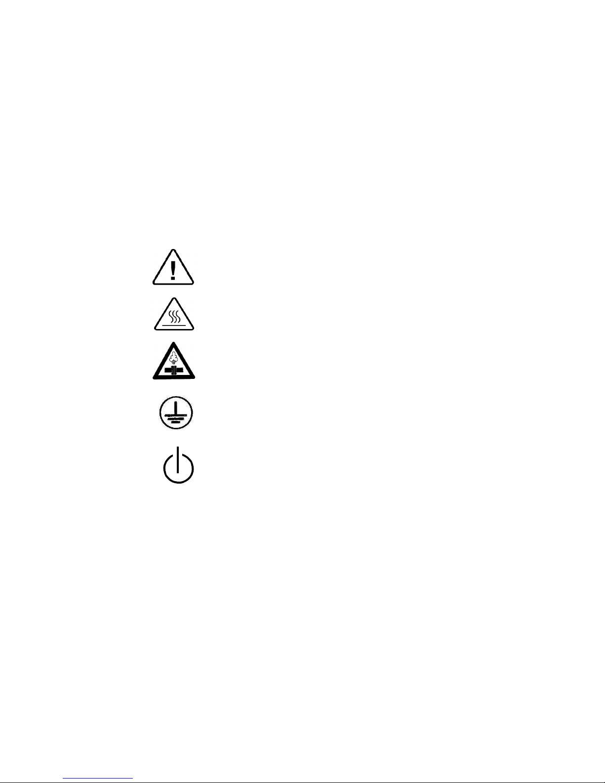
2. SYMBOL DESCRIPTION
Caution! Consult accompanying documents
Caution! Hot surface.
Caution! Hot steam.
Protective earth (Ground)
Stand by
Page 7
Page 5 of 102 Pages
3. INSTALLATION INSTRUCTIONS
The following utilities have to be connected (Refer to the drawing below ‘Rear View’
of the autoclave).
Power outlet, as detailed in the table below:
Power
3 Ph, 400V/50/60Hz
Recommended Circuit Breaker
20A
If the 3 phase autoclave has to be connected to a one phase power network, 1 x
230V, 50/60Hz., connect the 1ph 230V power source to the supplied switch box
that has a 1 phase input (from the power source) and a 3 phase output (to the
autoclave). See details at the end of this manual.
The power network must be protected by a current leakage relay.
Mineral-free water having a conductibility lower than 15µs (microsiemens),
through a 1/2” flexible hose.
To obtain water quality meeting requirements a deionization column or reverse
osmosis apparatus can be installed. The water must be delivered at a pressure of 23bar. A pressure reducer shall be installed at the water source outlet as instructed
below.
For fast cooling (if this option is provided):
Feed water from the water network, pressure 2-3bars, connected through a 1/2”
pipe. A pressure reducer shall be installed at the water source outlet as instructed
below.
Compressed air, from a mobile compressor or compressed air network at pressure
3-4 bars, will be set at 1.6-2bars at the autoclave inlet is to be connected by a
flexible conduit of 3/16”.
The air must be of instrumental quality filtered at 5µ and free of humidity and oil
drops.
Drain connected by 1/2” pipe, located at the rear of the unit. The chamber exhaust
and coolant water is evacuated to an open waste funnel. The drainage piping must
be heat resistant, to 80ºC, non-continuous flow.
Attention:
Connection of water system to the autoclave must be performed through "BACK
FLOW PREVENTION SYSTEM" installation as per EN 1717.
3.1 Installation Site
1. Install the autoclave according to the following guidelines:
2. Place the autoclave on the floor. Verify that the surface is leveled.
3. All utility supplies must be prepared in accordance with requirements,
before autoclave installation e.g. mineral-free and tap water, compressed
air, one or three-phase power network, connection to the drain of the
building.
4. Leave the space free around the autoclave for maintenance and service
requirements.
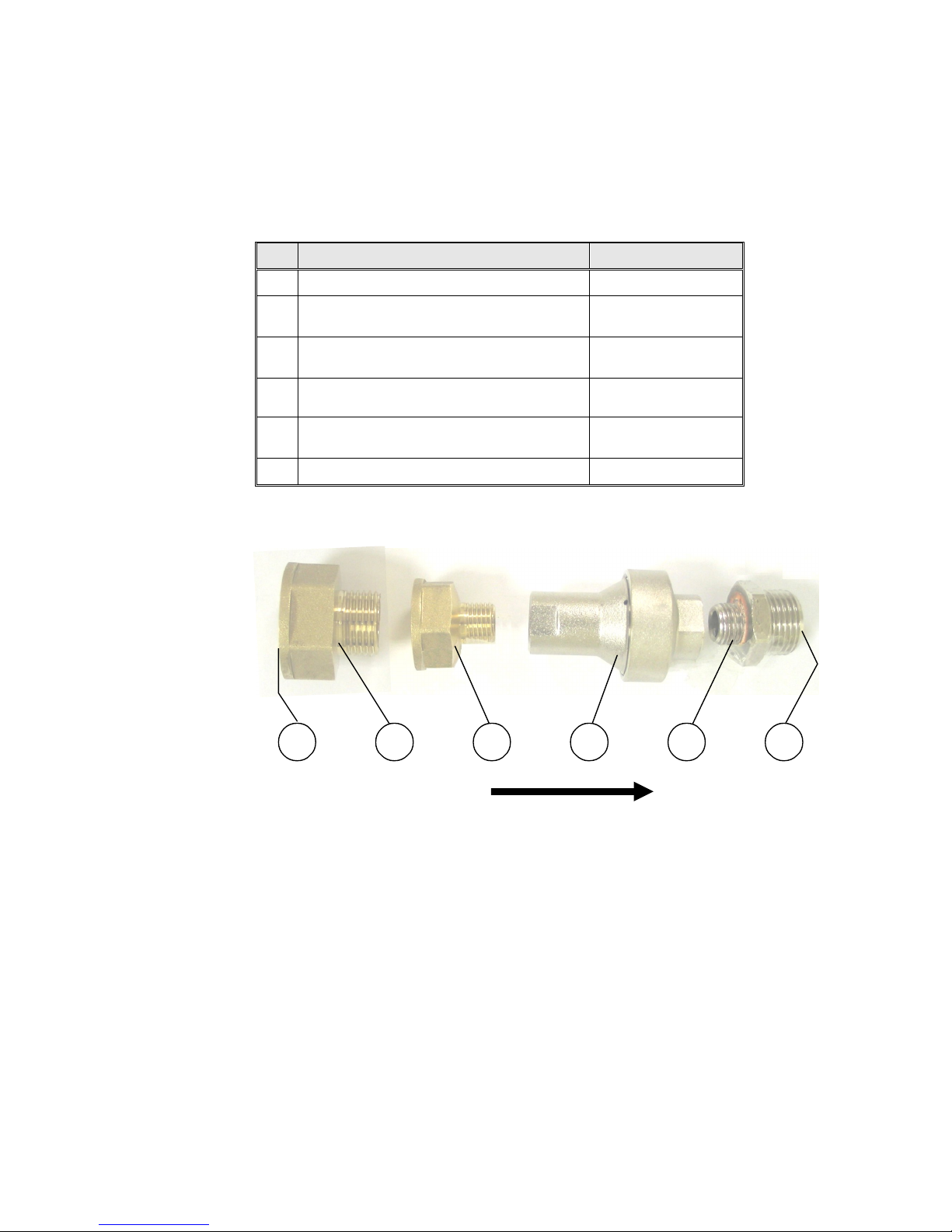
3.2 Connection of the pressure regulator
This paragraph refers to the pressure regulator of the feed water and to the
pressure regulator of the mineral free water.
1. Attach the pressure regulator to the facility's water outlet.
Page 8
Page 6 of 102 Pages
FLOW DIRECTION
54321
6
2. Connect the supplied flexible hose to the pressure regulator's assembly
outlet and to the autoclave's water inlet.
3. Verify that the pressure regulator is in right direction. The flow direction
is indicated by an arrow stamped on the pressure regulator.
4. Verify that water flows freely in the feed water and in the mineral free
water lines.
No. Description Cat No.
1 Side of water supply source N/A
2
Reducer, Female 3/4" BSP to Male
1/2" BSP, Brass
FIT100-0424
3
Reducer, Female 1/2" BSP to Male
1/4" BSP, Brass
FIT100-0425
4
Pres
sure Regulator, Water, In
-
Line,
with Strainer, 1/4 x 1.5 bar
GAU029-0059
5
Fitting, Adaptor, M 1/2" BSP x M 1/4"
BSP, Brass Ni plated
PNE100-0042
6 Side of flexible hose (to autoclave N/A
Page 9
Page 7 of 102 Pages
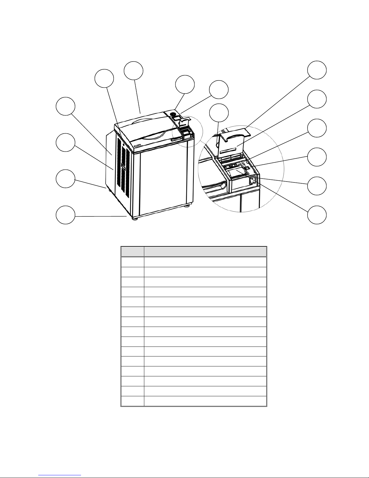
FRONT VIEW
No. Description
1 Front leg
2 Rear leg
3 Left service door
4 Left service door grip
5 Left service door lock
6 Door cover
7 Pressure gauge
8 Display
9 Keyboard
10 Printer cover
11 Paper slot and paper cutter
12 USB socket
13 RJ45 connector
14 Main switch
15 Printer
9
10
5
6
7
8
11
14
15
4
3
2
1
12
13
Page 10
Page 8 of 102 Pages
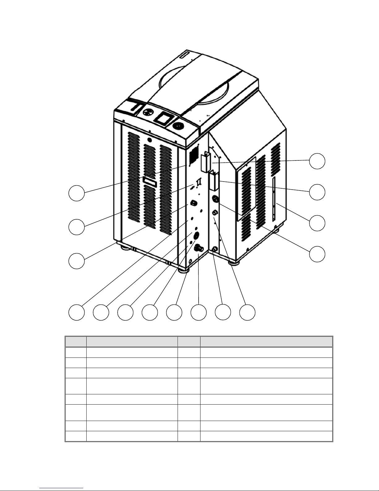
REAR VIEW
No. Description
No. Description
1 fan grill 9
air pressure regulator
2 circuit breaker 10
generator drain outlet
3 electrical cord
11 Generator mineral free water inlet
4
Vacuum pump city (tap)
water inlet
12 generator pressure gauge
5 compressed air inlet
13 side gage glass indicator tube
6
Tap water inlet for cooling
coil and drain
14 generator safety relief valve
7 autoclave air pressure gauge
15 chamber safety relief valve
8 autoclave drain outlet
7810111 2
3
4
5
6
14 131215
9
Page 11
Page 9 of 102 Pages
4. TESTS
4.1 Installation Tests
The service technician shall perform the following preliminary checks
before operating the autoclave:
a. Integrity Check
Perform a visual check to verify that there are no dents, scratches,
broken gauges, etc.
b Leveling Check
Check that the autoclave is leveled.
c. Leakage current test
Check the precise operation of the earth leakage relay.
d. Continuity Check
Check the continuity of the grounding connection.
At this stage operate the autoclave and continue with the tests:
e. Safety Check
Check the safety elements; safety valve and the door locking mechanisms.
f. Programs Check
Run basic programs of the autoclave and check the operation
sequences, the sterilization parameters etc.
g. Validation
Validate the sterilization cycles, taking in consideration the interface of
packaging/goods/autoclave.
After the above steps are performed, the autoclave is ready for operation.
4.2 Periodical Tests
PERIOD TEST
2 months Test the safety valve by operating it.
6 months
Remove the cover of the autoclave, tighten the, valves and connectors in
the controlbox.
Year
Check the continuity of the grounding connections.
Check the temperature and pressure calibration.
Perform validation of the autoclave.
Check the precise operation of the earth leakage relay.
Check that the autoclave is leveled.
Check the safety elements; safety valve, safety and cut-off thermostats
door locking mechanisms.
Run basic programs of the autoclave and check the operation sequences,
the sterilization parameters etc.
Check the water reservoir, piping, plastic parts and electric wires.
Check and tighten the piping joints to avoid leakage.
Check and tighten all screw connections in the control box, valves and
instrumentation.
Observe the closing device for excessive wear
5 years Observe the closing device for excessive wear
Safety tests (pressure vessel, efficiency, electrical) shall be performed in accordance
with local rules or regulations, by an authorized inspector.
Only an authorized technician shall perform the 6-months and yearly tests!
Page 12
Page 10 of 102 Pages
Check connections to distilled or mineral free water. Open the distilled or
mineral free water valves. Manually test the distilled or mineral free water
valves by over-riding the appropriate solenoid valves. If there are no leaks, –
leave the water manual inlet taps open.
1. Observe the gauge and see that the generator reaches working pressure.
Check that the jacket pressure gauge, reaches 2.4 bars (35 psi).
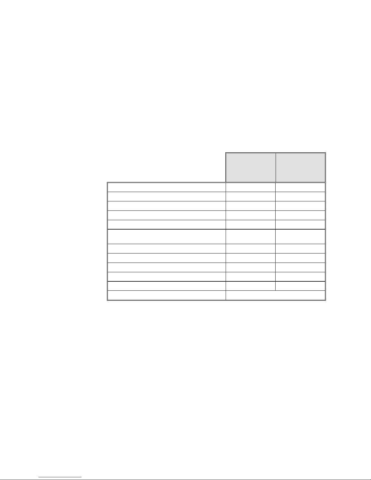
5. WATER QUALITY
Physical Characteristics and Maximum acceptable
contaminant levels in water or steam, for steam generator and
sterilizers
(According to EN 285:2006).
Contaminants
in water
supplied
to generator
Contaminants
in condensate
at steam inlet
to sterilizer
Evaporate residue
≤ 10 mg/l N/A
Silicate (SiO
2
≤ 1 mg/l ≤ 0.1 mg/l
Iron
≤ 0.2mg/l ≤ 0.1mg/l
Cadmium
≤ 0.005 mg/l ≤ 0.005 mg/l
Lead
≤ 0.05 mg/l ≤ 0.05 mg/l
Rest of heavy metals except iron,
cadmium, lead
≤ 0.1 mg/l ≤ 0.1 mg/l
Chloride (Cl)
≤ 2 mg/l ≤ 0.1 mg/l
Phosphate (P2O5)
≤ 0.5 mg/l ≤ 0.1 mg/l
Conductivity (at 25°C)
≤ 5 µs/cm ≤ 3 µs/cm
pH value (degree of acidity)
5 to 7.5 5 to 7
Hardness (Σ ions of alkaline earth)
≤ 0.02 mmol/l ≤ 0.02 mmol/l
Appearance
Colourless, clean, without sediments
Compliance with the above data should be tested in accordance with
acknowledged analytical methods, by an authorized laboratory.
Attention:
We recommend testing the water quality once a month. The use of water
that do not comply with the table above may have severe impact on the
working life of the sterilizer and can invalidate the manufacturer’s
guarantee.
5.1 Water for the Vacuum pump and drain cooling
The feed water supplied to the liquid ring vacuum pump must meet the
following requirements:
Hardness: 0.7 - 0.2 mmol/l.
Water temperature: shall not exceed 15°C.
Page 13

Page 11 of 102 Pages
Note:
The use of heavy scaled water for the vacuum pump cooling, can cause
blocking of the rotor and put the pump out of operation. This invalidates the
guarantee for the vacuum pump.
5.2 Reverse Osmosis
A Reverse Osmosis system may be used to improve the quality of the water
used to generate steam in the autoclave chamber. The use of mineral free will
contribute to better performance and longer life of the autoclave.
Page 14
Page 12 of 102 Pages
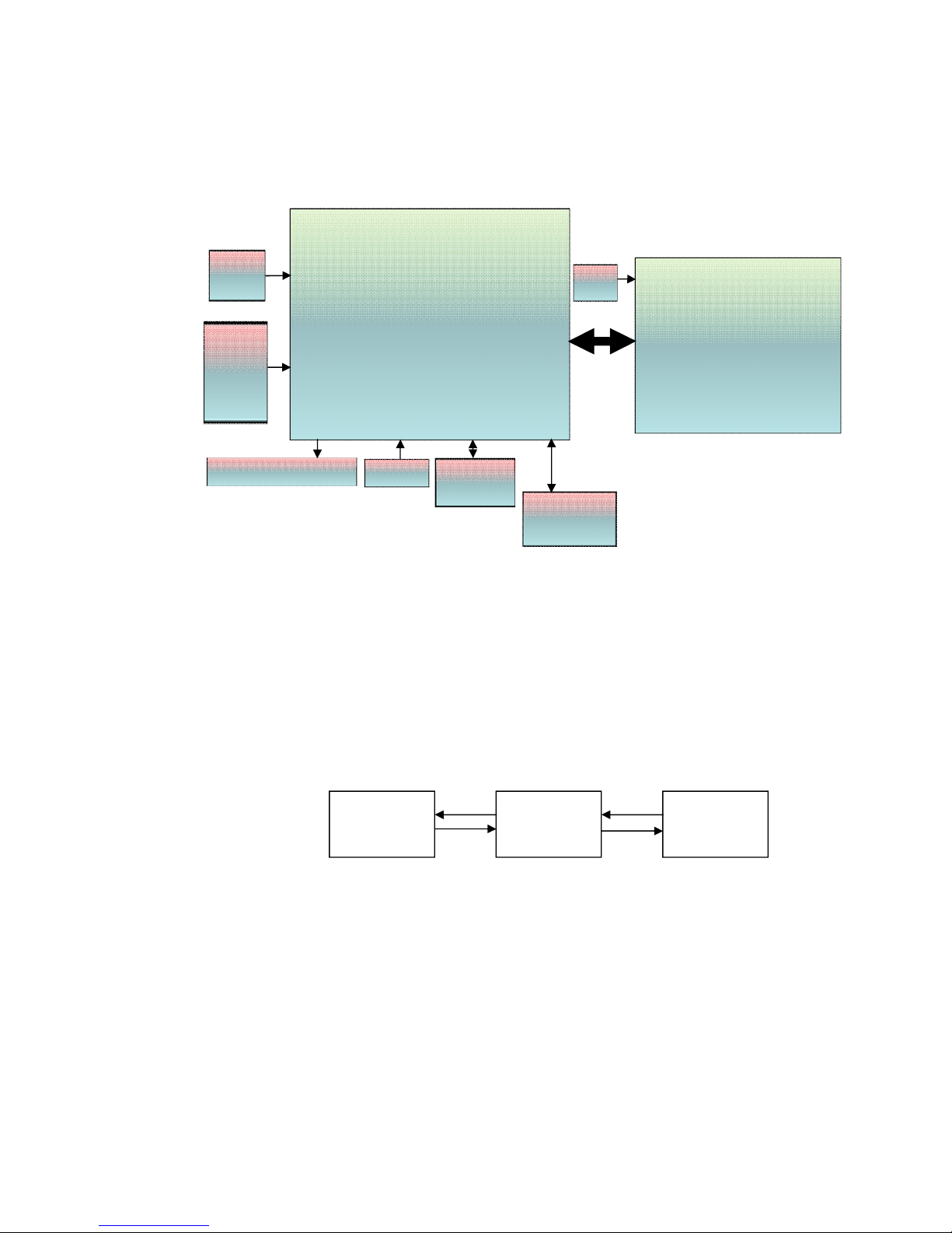
6. DESCRIPTION OF THE CONTROL SYSTEM.
BLOCK DIAGRAM HARDWARE SOFTWARE COMPONENTS
6.1 Application system architecture
The system is divided into three main sections (dll)
1. GUI – holds all the Human Machine interface including the main
application screen and all the configuration screens which enable the user
to handle the machine.
2. Logic – holds all the application logic for running the machine.
3. Utilities – Holds general functionality which is used by the logic section
and the GUI section e.g: converting function for displaying different
pressure or temperature units type, languages etc..
Mapping of the software to the hardware – see Software Development Plan
The Hardware architecture is based on Freescale i.MX27 PDK Evaluation
Board.
GUI LOGIC UTILITY
Main board
-CPU +memory- Backup power input
-MCIMX27LVOP4 A+MC13783VK5
-R.T.C (including Battery) M41T81SM6E
-Memory card expansion
MT46H32M16LFBF-
6:B+EPM570F256C5+S71WS256PD0HF3SR0C+K
9F1G08ROB-JIB000
Ethernet
Am79C874
I/O Board
CPU- STM32F103R6T6
-24 Digital Outputs
-2 Analog outputs
-9 Digital inputs
-4 Analog Inputs 4-20mA
-6 Analog inputs Temp pt100
-3 Inputs water level
Keypad
Graphic Display 3.5 "
USB Memory
socket
ISP1504ABS
24/12
VDC
Input
COM1
(RS232)
MAX323
2CSE+
Printer
24/12
VDC
Page 15
Page 13 of 102 Pages
6.2 Description of the programmable component:
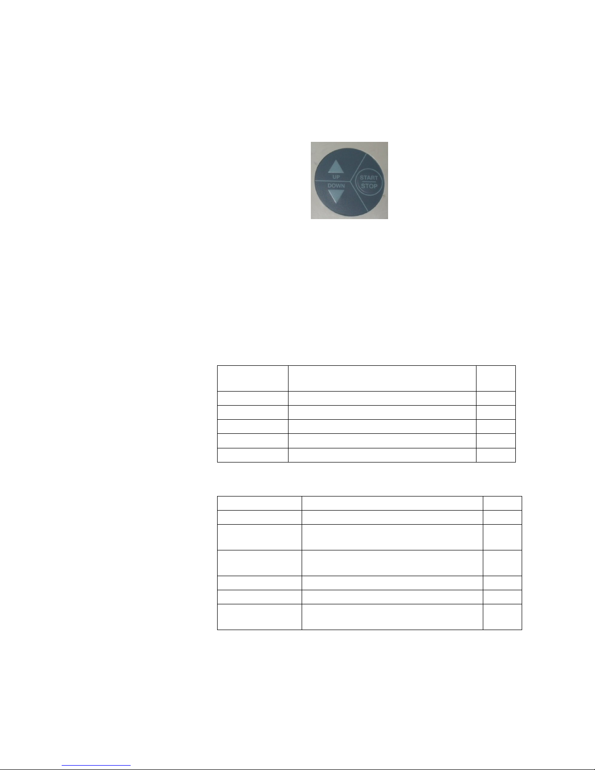
6.2.1 Interfaces to users
Keypad: The keypad has three push buttons:
o Down key
o Up key
o Start/stop key
Display: The control system has a graphical display
USB socket: The USB socket is intended to load cycles'
history from flash a memory (disk on key). The
received file is in txt format that can be loaded
onto a PC.
6.2.2 Inputs and Outputs
6.2.2.1 Analog inputs
Analog
inputs
Description JP
PT100-1 PT-100 Chamber Temperature J2
PT100-2 PT-100 Ref Temperature1 J3
PT100-4 PT-100 Drain (option) J5
Pressure 1 4-20mA main chamber pressure control J7/1
Electrode 1 Water level camber/generator control 1 J11/1
6.2.2.2 Digital inputs
Digital Inputs Description JP
Door 1 closed Indicate door 1 closed J12/1
Door 1 locked
Indicate door 1 locked (3850/70
models)
J12/8
Door1 open
switch
Indicate to command to close / open
Door1 (3850/70 models)
J12/6
Water supply Indicate water supply (Cooling option) J12/2
Air supply Indicate Air supply (Cooling option) J12/4
Distilled water
supply
Indicate distilled water supply J12/3
Page 16

Page 14 of 102 Pages
-
6.2.2.3 Digital outputs
Digital Outputs Description JP
Generator heaters SSR that operates the chamber heaters J13/6
Water pump /
water valve
Option , relay that operates the water
pump / water valve
J13/10
Vacuum pump /
water to vacuum
pump
Option , relay that operates the
vacuum pump / water to vacuum
pump
J13/12
Vacuum
Option, vacuum valve for pre vacuum
option
J14/2
Compressed air
to chamber
Option, compressed air to chamber
valve for cooling option
J14/4
Top/slow
exhaust
Top/slow exhaust valve J14/6
Fast exhaust Fast exhaust valve J14/8
Atmospheric air Atmospheric air valve J14/10
Cool drain
Option, cool drain valve for cooling
option
J14/12
Steam to
chamber
Steam to chamber valve J14/14
Water to coil
Option, water to coil valve for cooling
option
J14/16
Compressed air
to coil
Option, compressed air to coil valve
for cooling option
J15/2
Closed door 1
Relay that operates the electrical
cylinder to close the door
J15/4
Open door 1
Relay that operates the electrical
cylinder to open the door
J15/6
6.2.3 Actuators
The control system operates electrical valves (solenoids), Electric
cylinder motors, pneumatic cylinders, electric pumps, heaters.
6.2.4 On / off switch
A Rocker Switch 250V AC, 16A
Page 17
Page 15 of 102 Pages
6.3 Software development plan:
The hardware is consisted of cards: MAIN and IO
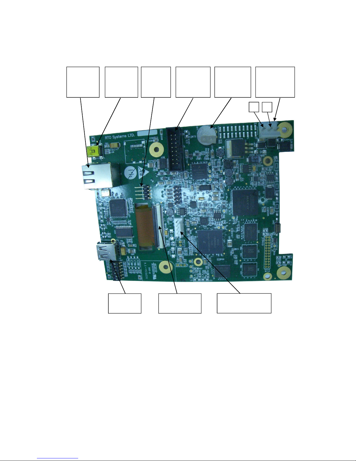
6.3.1 Main card
Operating system (MAIN card)
The Operating system is Microsoft Windows CE version 6. The
code to the Operating system is supplied by Microsoft. The
connection code between the Operating system and the
hardware components (BST – Board Support Package) is
supplied by FreeScale. Minimum suitability for this
"Tuttnauer" project is performed in this code.
Development tools (MAIN card)
The software develop environment is on Microsoft Visual
Studio 2005 that includes the Microsoft Platform Builder for
Windows CE 6.0. The specific Tuttnauer system application is
written in C Sharp.net on Microsoft Compact Framework .net
Power Supply
Connector
(24V DC)
Connector to
printer
+
Ethernet
ConnectorSDNot in use
USB
Connector
-
Connector
to IO Board
Connector to
LCD display
Connector
to Keypad
Lithium coin
battery T.H
Horizontal
3V 48mAh
J5
BT1
J8
J4
P2
P4
T1
P3
J3
Page 18
Page 16 of 102 Pages
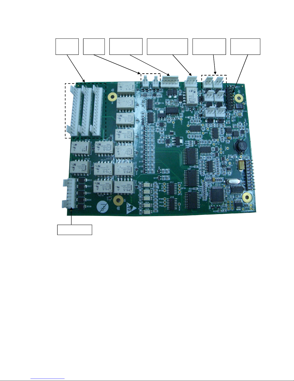
6.3.2 IO Card
IO card is an independent card. It checks the card by a method of a
continuous scan of all the ports, saving the data in the memory and
transporting this data according to the request in the communication
channel RS-232 to the personally adapted protocol.
At the end of the check process of the digital and analog ports, the
communication channel is checked, in case of receiving a request,
the request is checked and if the request is legitimate it will be taken
care of.
The IO card is controlled by the MAIN card. Only when requests
are received from the MAIN, the requests will be checked and
performed.
The IO card will perform an electrical restart of the systems (IO
card) if it does not receive requests within 5 seconds. In the next
request received from the MAIN, the IO card will indicate to the
requester of IO card systems restart.
Analog inputs
(PT-100)
Analog inputs
Pressure (4
-
20mA)
Analog inputs
electrodes
J
J
J6
J3
J4J1
J7J11
J16J17
J13J15J14
Connection to
MAIN Board
Analog
outputs
Digital
outputs
Digital outputs
J12
Page 19

Page 17 of 102 Pages
The "brain" in the IO card runs on microcontroller type:
STM32F103R6T6.
The Microcontroller is an electrical Integrated circuit with an
actualized complete system (SoC) including a processing unit,
external interfaces, memory, etc.
The Microcontroller is constructed of a number of main
components:
1. Central processing unit – the main component in the
microcontroller is a central processing unit (CPU) This unit is
in charge of receiving the request (command) code from the
memory, deciphering, receiving variable data from the
memories and performing the command.
2. Memory – divided into 2 sections.
2.1 software memory – in this memory the software that
samples the IO card and request (command) from the
user are saved. As this memory is a flash memory it is
possible to burn the code many times (efficient to the
development stage).
2.2 information memory – in this memory the data and other
variables values are saved. This memory is not flash
memory, but is RAM memory.
Digital / Analog ports (in/out) – through them the
microcontroller can receive data of digital/analog
signs from the system, save them and pass them on
respectively to the user request.
Ports (in / out) to the communication – in the IO card
there is a UART component. This component enables
communication with the MAIN card through the RS232 in suitable protocol.
Page 20

Page 18 of 102 Pages
6.3.3 MAIN and IO cards :communication protocol between IO board
to Main Board
Communication protocol between IO to Main boards is described
below.
The communication manged by the Main board (master), the IO
functions as slave
1. There are six communication functions.
The communication functions (to read or write) identified by
number.
The communication functions listed below:
1.1 01 - Read – command to IO send all the information of
digital analog inputs.
1.2 02 - Write – Command to IO to activate analog and
digital outputs.
1.3 03 - Read version – IO software version to verify the
version.
1.4 04 – N.A.
1.5 05 - Read number that identifies the ID of IO board and
the software version.
1.6 06 - Write (only at the first time) to IO his ID and
software number.
2. First Byte (Byte 1).
The first byte identifies ID functionality request. It can be one
of the numbers in a paragraph.
3. The second byte will present the data size if the main board
asks to write information to the IO. If the request is to read this
byte will be 00.
4. The number of the request. This number is increased from 00ff.
5. Check sum of the package – to prevent mail functionality of the
board if there is interference in communication.
6. The information package transfer. The information contains
number of the input or output and data for/from each I/O.
Bytes identify number of input or output followed by two bytes
containing the data of the input or outputs.
7. Last byte contains a check sum of the entire package that is
transferred. This is to verify that the information is not
corrupted.
Example
The main board sends:
01;00;0003;0004;
01 Ask to Read inputs.
00 not transfer information.
0003 Request number 3
0004 Checksum to verify the request
Page 21
Page 19 of 102 Pages
7. CHECKING AND CHANGING PARAMETERS AND OTHER DATA
The control system prevents changing programs if the door is closed. This protection
is intended to avoid program changes if the autoclave is loaded. If the operator for
example inserts the load into the chamber, closes the door and leaves the room and
another operator/user tries to change the program, the operator/user will not be able to
do this unless the door is opened and the load inside the chamber can be seen.
7.1 Directories and subdirectories
The Technician may perform the following:
DIRECTORY SUBDIRECTORY
SECOND
SUBDIRECTORY
Cycle Parameters –
applicable only for Custom
1 and Custom 2 programs
See sec. 6.4 “Cycle Parameters
(Custom 1)”
System Parameters
Print Rate All
Print Rate Sterilization
Screen Saver
Inputs / Outputs
View digital inputs state
View digital outputs state
Test digital outputs
View analog inputs state
History
View old cycle history
Last 10 cycles
Last 50 cycles
All cycles history
Export history to USB
Maintenance
set date and time
Export gain offset to USB
Reset atmospheric pressure
Test RTC
Printer test
Print all gain and offset
Advanced options
Start cycle by clock
Enable cycles
Set language
Set Temperature units
Set pressure units
Export all settings to USB device
Add Custom Program
Set Master IP address
Set mac address
Version information
View current version information
View factory default version
information
View previous version information
Page 22

Page 20 of 102 Pages
9.3.1 PulsNum. – No. of pulses in the prevacuum stage
If the autoclave is not equipped with a vacuum pump – the parameter
value is "0".
Entry Code – 11
Resolution – 1
Minimum Value – 1
Maximum Value – 5
Set
value
Cycle 1-2 3 4 5 6-7
8-9
-
10
11 12 13 14
Value
1 1 1 3 1 1 1 1 1 1
9.3.2 VacDip1 – Vacuum value in the first pulse
Defines the vacuum value in pulse no.1 of the prevacuum stage.
Entry Code – 11
Resolution – 1kpa
Minimum Value – 1kpa
Maximum Value – 90kpa
Set
value
Cycle
1-2 3 4 5 6-7
8-9
-
10
11 12 13 14
Value
25 25 25 25 25 25 25 25 25 18
9.3.3 VacDip2 – Vacuum value in the remaining pulses
This value defines the vacuum in the remaining pulses in the
prevacuum stage (not just pulse no. 2)
Entry Code – 11
Resolution – 1kpa
Minimum Value – 1kpa
Maximum Value – 90kpa
Set
value
Cycle 1-2 3 4 5 6-7
8-9-
10
11 12 13 14
Value
25 25 25 25 25 25 25 25 25 18
9.3.4 Vac Time 1 – Vacuum Time in the First Pulse
This value defines the time the system will continue to maintain
vacuum for the first pulse after reaching Vac Dip1
Entry Code – 11
Resolution – 30sec
Minimum Value – 1sec
Maximum Value – 1800sec
Set
value
Cycle 1-2 3 4 5 6-7
8-9-
10
11 12 13 14
Value
120 120 120 120 240 120 120 120 120 3
Page 23
Page 21 of 102 Pages
9.3.5 Vac Time2– Vacuum Time in the remaining pulses.
This value defines the time the system will continue to maintain
vacuum after reaching Vac Dip2 for the remaining pulses.
Entry Code – 11
Resolution – 30sec
Minimum Value – 1sec
Maximum Value – 1800sec
9.3.6 Puls Press – pulse pressure during pre-vacuum stage.
This parameter is used to set the maximum pressure in each pulse of
the pre-vacuum stage.
Access Code – 13
Resolution – 5
Minimum Value – 75
Maximum Value – 200
Set
value
Cycle
1-2 3 4 5 6-7
8-9-
10
11 12 13 14
Value
140 140 140 140 140 140 140 140 140 140
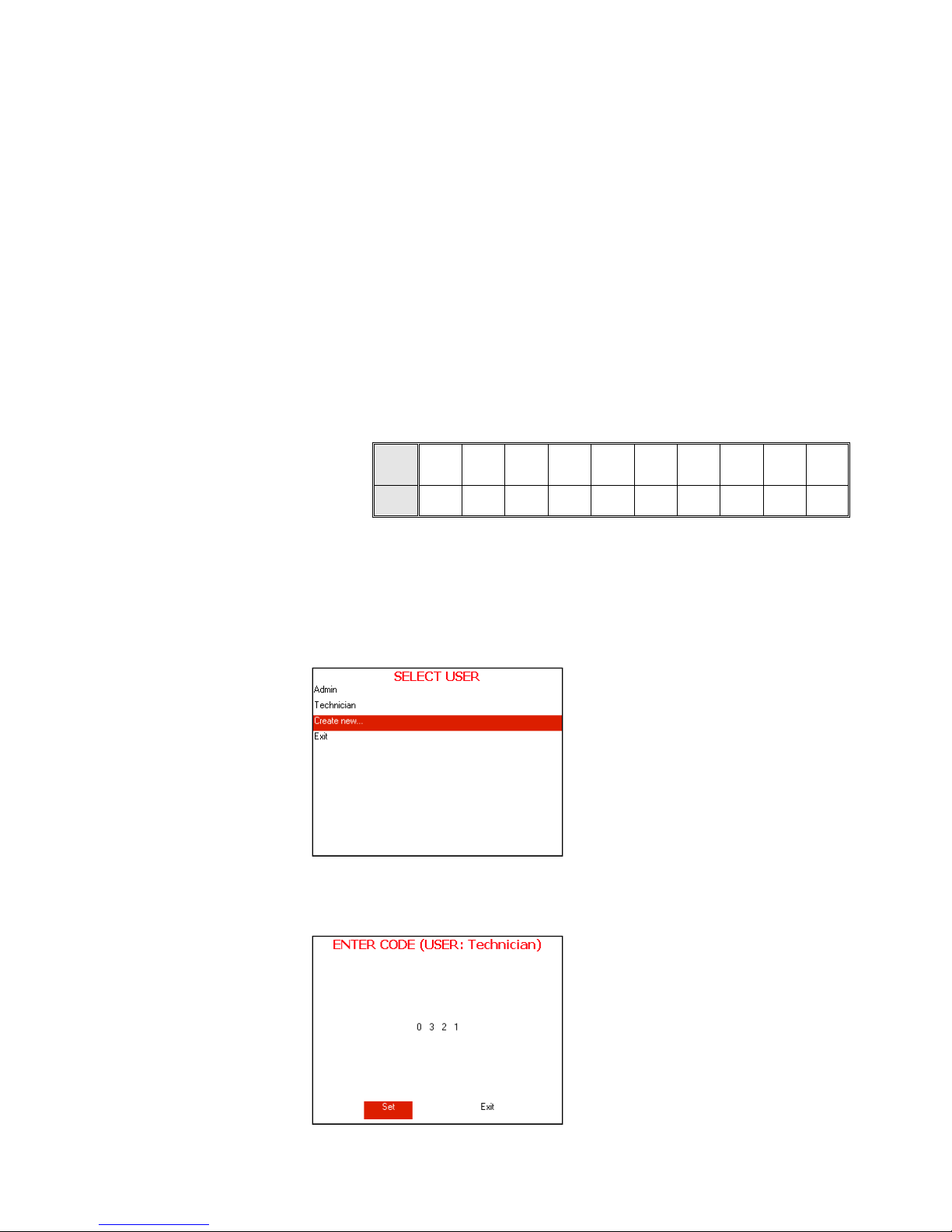
7.2 Entering the main menu
1. Enter the SELECT USER screen by pressing the UP and DOWN keys
simultaneously.
To exit the SELECT USER screen move the cursor to Exit by pressing
UP or DOWN keys and then press START/STOP key.
SELECT USER screen will be displayed.
2. Move the cursor to Admin and press START/STOP key. The following
screen will be displayed:
Page 24
Page 22 of 102 Pages
3. 0000 is displayed on the screen with the cursor blinking on the right
digit.
4. To increase or decrease the digits, press the UP or DOWN keys.
5. After changing the code to 0321 move the cursor to Set by pressing the
START/STOP key.
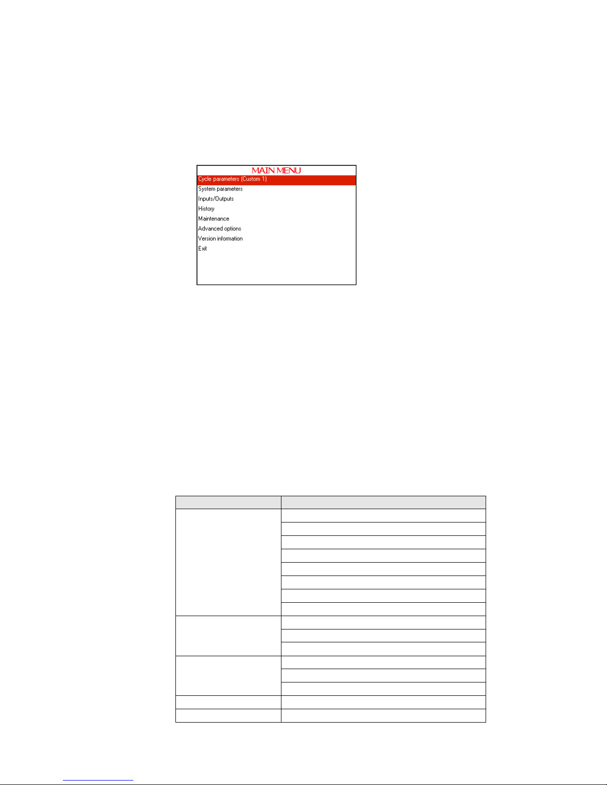
6. When Set is blinking, press the UP or DOWN keys to enter the MAIN
MENU of the autoclave.
The following screen will be displayed:
In order to exit the ENTER CODE screen move the cursor to Exit by
pressing START/STOP Key. when Exit is blinking press UP or
DOWN keys.
7. To browse through the directories, use the UP or DOWN keys.
8. When the required directory is blinking, press the START/STOP key.
The required screen will be displayed.
9. In order to exit this screen follows one of the next:
Move the cursor to Exit with the UP or DOWN keys and select it
by pressing the START/STOP key.
Press the UP and DOWN keys simultaneously.
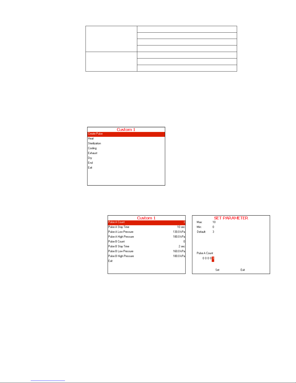
7.3 Cycle Parameters (Custom 1)
This directory applicable only for custom 1 and custom 2 programs
Subdirectory Property
Create Pulse
Pulse A Count
Pulse A Stay Time
Pulse A Low Pressure
Pulse A High Pressure
Pulse B Count
Pulse B Stay Time
Pulse B Low Pressure
Pulse B High Pressure
Sterilization
Sterilization Temperature
Sterilization Time
F0 Mode
Cooling
Cool mode
Cool End Temperature
Cool Exhaust Rate
Exhaust Exhaust Mode
Dry Dry Heat On 1
Page 25
Page 23 of 102 Pages
Dry Heat Off 1
Dry first stage time
Dry Heat On 2
Dry Heat Off 2
End
End Temperature
Multiple Cycles
Multiple Cycles Gap
This directory includes seven subdirectories
These subdirectories enable to see and change the cycle parameters.
Therefore it is necessary to choose the required cycle before entering the
"MAIN MENU".
For seeing or changing the parameters proceed as follows:
Choose and enter cycle parameters
The following screen will display:
7.3.1 Create Pulse
7.3.1.1 Pulse A Count
Choose and enter Pulse A Count
SET PARAMETER screen will be displayed
Set the required value, move to Set and press UP or
DOWN keys to confirm the parameter value.
In order to exit move the cursor to Exit and press UP or
DOWN keys
7.3.1.2 Pulse A Stay Time
Repeat the action mention in 7.4.1.1 Pulse A Count
Typical display for
Create Pulse
subdirectory
Page 26
Page 24 of 102 Pages
7.3.1.3 Pulse A Low Pressure
Repeat the action mention in 7.4.1.1 Pulse A Count
7.3.1.4 Pulse A High Pressure
Repeat the action mention in 7.4.1.1 Pulse A Count
7.3.1.5 Pulse B Count
Repeat the action mention in 7.4.1.1 Pulse A Count
7.3.1.6 Pulse B Stay Time
Repeat the action mention in 7.4.1.1 Pulse A Count
7.3.1.7 Pulse B Low Pressure
Repeat the action mention in 7.4.1.1 Pulse A Count
7.3.1.8 Pulse B High Pressure
Repeat the action mention in 7.4.1.1 Pulse A Count
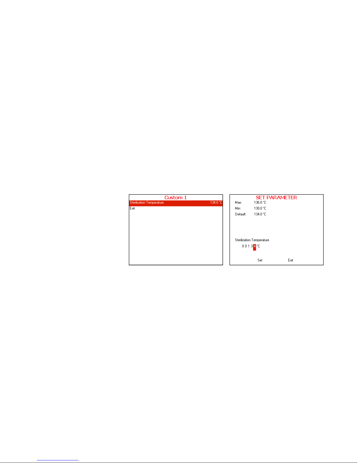
7.3.2 Heat
7.3.2.1 Sterilization Temperature
Choose and enter Sterilization Temperature
SET PARAMETER screen will be displayed
Set the required value, move to
Set and press UP or
DOWN keys to confirm the parameter value.
In order to exit move the cursor to Exit and press UP or
DOWN keys
7.3.3 Sterilization
7.3.3.1 Sterilization Temperature
See 7.4.2.1 Sterilization Temperature
7.3.3.2 Sterilization Time
Repeat the action mention in 7.4.2.1 Sterilization
Temperature
7.3.3.3 F0 Mode
Repeat the action mention in 7.4.2.1 Sterilization
Temperature
Typical display for
Sterilization Temperature
subdirectory
Page 27
Page 25 of 102 Pages
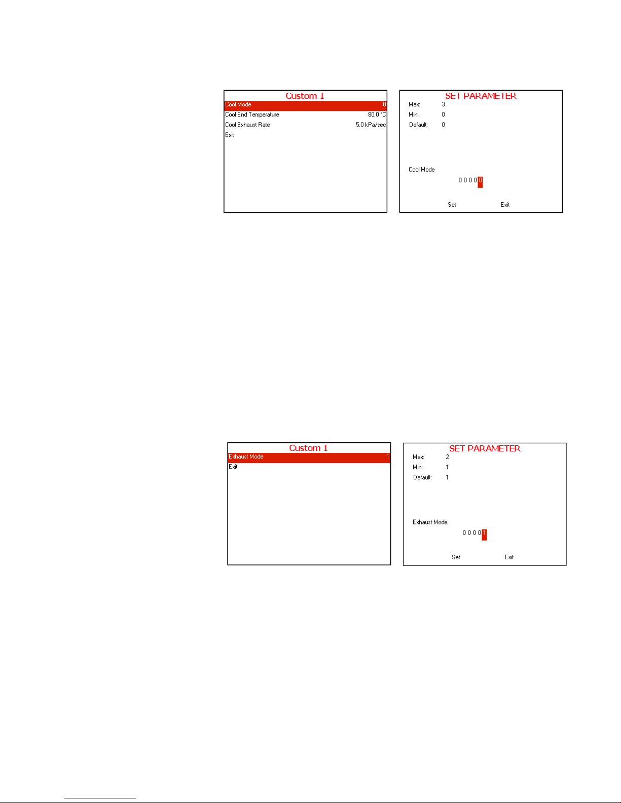
7.3.4 Cooling
7.3.4.1 Cool Mode
Choose and enter Cool Mode
SET PARAMETER screen will be displayed
Set the required value, move to Set and press UP or
DOWN keys to confirm the parameter value.
In order to exit move the cursor to Exit and press UP or
DOWN keys
7.3.4.2 Cool End Temperature
Repeat the action mention in 7.4.4.1 Cool Mode
7.3.4.3 Cool Exhaust Rate
Repeat the action mention in 7.4.4.1 Cool Mode
7.3.5 Exhaust
Exhaust Mode
Choose and enter Exhaust Mode
SET PARAMETER screen will be displayed
Set the required value, move to Set and press UP or
DOWN keys to confirm the parameter value.
In order to exit move the cursor to Exit and press UP or
DOWN keys
Typical display for
Cool Mode
subdirectory
Typical display for
Exhaust Mode
subdirectory
Page 28

Page 26 of 102 Pages
7.3.6 Dry
7.3.6.1 Dry Heat On 1
Choose and enter Dry Heat On 1
SET PARAMETER screen will be displayed
Set the required value, move to Set and press UP or
DOWN keys to confirm the parameter value.
In order to exit move the cursor to Exit and press UP or
DOWN keys
7.3.6.2 Dry Heat Off 1
Repeat the action mention in 7.4.6.1 Dry Heat On 1
7.3.6.3 Dry first stage time
Repeat the action mention in 7.4.6.1 Dry Heat On 1
7.3.6.4 Dry Heat On 2
Repeat the action mention in 7.4.6.1 Dry Heat On 1
7.3.6.5 Dry Heat Off 2
Repeat the action mention in 7.4.6.1 Dry Heat On 1
7.3.7 End
7.3.7.1 End Temperature
Choose and enter End Temperature
SET PARAMETER screen will be displayed
Set the required value, move to Set and press UP or
DOWN keys to confirm the parameter value.
In order to exit move the cursor to Exit and press UP or
DOWN keys
Typical display for
Dry Heat On 1
subdirectory
Typical display for
End
Temperature
subdirectory
Page 29
Page 27 of 102 Pages
7.3.7.2 Multiple Cycles
Repeat the action mention in 7.4.7.1 End Temperature
7.3.7.3 Multiple Cycles Gap
Repeat the action mention in 7.4.7.1 End Temperature
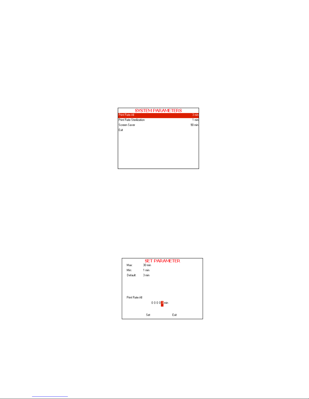
7.3.8 System Parameters
This directory includes three subdirectories
The following screen will be displayed when entering SYSTEM
PARAMETERS
directory:
1. In order to enter to the sub directories move the cursor by
pressing
UP or DOWN keys to the required item and press
START/STOP key
2. In order to exit this screen follows one of the next:
Move the cursor to Exit with the UP or DOWN keys and
select it by pressing the START/STOP key.
Press the UP and DOWN keys simultaneously.
7.3.9 Print Rate All
This subdirectory enables to change the printing rate during the
whole cycle except sterilization stage
1. To increase or decrease the digits, press the UP or DOWN
keys.
2. After changing the value move the cursor to Set by pressing the
START/STOP key.
3. When Set is blinking, press the UP or DOWN keys in order to
confirm changes and return to the previous screen.
4. In order to exit this screen follows one of the next:
Page 30

Page 28 of 102 Pages
In order to exit this screen move the cursor to Exit with the
START/STOP key and select it by pressing the UP or
DOWN keys.
Press the UP and DOWN keys simultaneously.
7.3.10 Print Rate Sterilization
This subdirectory enables to change the printing rate during
sterilization stage
1. To increase or decrease the digits, press the UP or DOWN
keys.
2. After changing the value move the cursor to Set by pressing the
START/STOP.
3. When Set is blinking, press the UP or DOWN keys in order to
confirm changes and return to the previous screen.
4. In order to exit this screen follows one of the next:
In order to exit this screen move the cursor to Exit with the
START/STOP key and select it by pressing the UP or
DOWN keys.
Press the UP and DOWN keys simultaneously.
7.3.11 Screen Saver
This subdirectory enables the operator to set the screen saver time.
The default time value is 90 minutes. It is possible to increase or
decrease the time value up to a maximum of 600 minutes or down
to a minimum 0 minutes.
When entering the Screen Saver screen, t he time will be
displayed. The cursor is blinking on the "minute" digit.
The time is displayed in the form “0000” min.
Page 31

Page 29 of 102 Pages
1. To increase or decrease the digits, press the UP or DOWN
keys.
2. After changing the value move the cursor to Set by pressing the
START/STOP.
3. When Set is blinking, press the UP or DOWN keys in order to
confirm changes and return to the previous screen.
4. In order to exit this screen follows one of the next:
In order to exit this screen move the cursor to Exit with the
START/STOP key and select it by pressing the UP or
DOWN keys.
Press the UP and DOWN keys simultaneously.
7.4 Inputs/Outputs
This directory includes four subdirectories
The following screen will be displayed when entering
INPUTS/OUTPUTS
directory:
1. In order to enter to the sub directories move the cursor by pressing
UP
or DOWN keys to the required item and press START/STOP key
2. In order to exit this screen follows one of the next:
Move the cursor to Exit with the UP or DOWN keys and select it
by pressing the START/STOP key.
Press the UP and DOWN keys simultaneously.
7.4.1 View digital inputs state
1. In order to exit this screen follows one of the next:
Page 32

Page 30 of 102 Pages
In order to exit this screen move the cursor to Exit with the
START/STOP key and select it by pressing the UP or
DOWN keys.
Press the UP and DOWN keys simultaneously.
7.4.2 View digital outputs state
This subdirectory enables to view the digital outputs state
1. In order to exit this screen follows one of the next:
In order to exit this screen move the cursor to Exit with the
START/STOP key and select it by pressing the UP or
DOWN keys.
Press the UP and DOWN keys simultaneously.
7.4.3 Test digital outputs
This subdirectory enables to test the digital outputs state
1. In order to test the digital output move the cursor by pressing
UP or DOWN keys to the required item and press
START/STOP key and verified that the required item
operates.
2. In order to exit this screen follows one of the next:
Move the cursor to Exit with the UP or DOWN keys and
select it by pressing the START/STOP key.
Press the UP and DOWN keys simultaneously.
Page 33

Page 31 of 102 Pages
7.4.4 View analog inputs state
This subdirectory enables to view the analog inputs state
1. In order to exit this screen follows one of the next:
In order to exit this screen move the cursor to Exit with the
START/STOP key and select it by pressing the UP or
DOWN keys.
Press the UP and DOWN keys simultaneously.
7.5 Calibration
7.5.1 Calibration components
This directory describes the calibration of 4 sensors in the
Sensor name Sensor function
1.
ChambPress
Reads the pressure in the chamber.
2. ChambTemp
Reads the temperature in the chamber.
7.5.2 Required equipment for calibration
PT Simulator (for temperature calibration).
Reference temperature sensor.
Reference pressure tool: pressure gauge.
7.5.3 Calibrating the sensors
ANALOG INPUTS
ChambPress 113.4
Chamb Temp 082.8
EXIT
Choose the sensor required to calibrate
among the 4 sensors available with the
UP
and DOWN keys.
When it is blinking select it by pressing
the START/STOP
key.
CALIBRATION
Change
GainOffset
Calc.
GainOffset
Restore Last
Restore Default
EXIT
Sensor name Current value
Move to Calc. GainOffset with the UP
and DOWN keys, and then when it is
blinking select it with the START/STOP
key.
Page 34

Page 32 of 102 Pages
Calibrating the pressure in the chamber “ChambPress”
Calibrate the low pressure of the chamber
To perform the low pressure calibration, insert your reference
pressure tool in the autoclave and operate a vacuum test.
Open the autoclave’s door and read the
value displayed on
your tool.
AL (actual pressure low value): change the AL with the
value read by your reference tool (use UP and DOWN
keys to increase and decrease the value and the
START/STOP key to move ahead from digit to digit).
RL (read pressure low value): change the RL with this
same value (use UP and DOWN keys to increase and
decrease the value and the START/STOP key to move
ahead from digit to digit).
To save the data move to SET by pressing the
START/STOP key and when it is blinking press the UP
key.
Calibrate the high pressure of the chamber
To perform the calibration of the high pressure, insert your
reference pressure tool in the autoclave and operate a
program of 134°C. Perform the calibration when the
autoclave reaches the sterilization stage.
AH (actual pressure high value): change the AH with the
value read by your reference tool (use UP and DOWN
keys to increase and decrease the value and the
START/STOP key to move ahead from digit to digit).
RH (read pressure high value): change the RH with this
same value (use UP and DOWN keys to increase and
decrease the value and the START/STOP key to move
ahead from digit to digit).
To save the data move to SET by pressing the
START/STOP key and when it is blinking press the UP
key.
Calibrating the temperature in the chamber “ChambTemp”
Calibrate the low temperature of the chamber
To perform the calibration of the low temperature, insert your
reference temperature tool in the autoclave, near of the Pt100
of the chamber when the autoclave is cold.
AL (actual temperature low value): change the AL with
the value read by your reference tool (use UP and
DOWN keys to increase and decrease the value and the
START/STOP key to move ahead from digit to digit).
RL (read temperature low value): change the RL with this
same value (use UP and DOWN keys to increase and
decrease the value and the START/STOP key to move
ahead from digit to digit).
To save the data move to SET by pressing the
START/STOP key and when it is blinking press the UP
key.
Page 35

Page 33 of 102 Pages
Calibrate the high temperature of the chamber
To perform the calibration of the high temperature, insert
your reference pressure tool in the autoclave, near of the
PT100 and operate a program of 134°C. Perform the
calibration when the autoclave reaches the sterilization stage.
AH (actual temperature high value): change the
AH
with
the value read by your reference tool (use
UP
and
DOWN
keys to increase and decrease the value and the
START/STOP
key to move ahead from digit to digit).
RH (read temperature high value): change the RH with
this same value (use UP and
DOWN
keys to increase
and decrease the value and the
START/STOP
key to
move ahead from digit to digit).
To save the data move to
SET
by pressing the
START/STOP
key and when it is blinking press the
UP
key.
7.6 History
This directory includes two subdirectories
The following screen will be displayed when entering HISTORY directory:
1. In order to enter to the sub directories move the cursor by pressing UP or
DOWN keys to the required item and press START/STOP key
2. In order to exit this screen follows one of the next:
Move the cursor to Exit with the UP or DOWN keys and select it by
pressing the START/STOP key.
Press the UP and DOWN keys simultaneously.
7.6.1 View old cycle history
This subdirectory enables to print the 100 previous cycles.
The following screen will be displayed when entering View old
cycle history subdirectory:
Page 36

Page 34 of 102 Pages
1. Choose the required cycle according to cycle number, date
and time with the
UP or DOWN keys
2. Press the START/STOP key. The printer will print the
printout of the required cycle
3. In order to exit this screen follows one of the next:
Move the cursor to Exit with the UP or DOWN keys and
select it by pressing the
START/STOP key.
Press the UP and DOWN keys simultaneously.
7.6.2 Export history to USB
This subdirectory enables to Export history to USB device.
1. Insert the USB device into the USB Socket
2. Move the cursor to
Export history to USB
3. Press the START/STOP key.
4. The following screen will be displayed:
5. Move the cursor to the required item and press
START/STOP
key
6. The following screen will be displayed:
7. Remove the USB device from the USB Socket
8. In order to exit this screen and return to HISTORY OPTIONS
screen press START/STOP key.
9. In order to exit the HISTORY OPTIONS screen follows one
of the next:
Move the cursor to Exit with the UP or DOWN keys and
select it by pressing the START/STOP key.
Press the UP and DOWN keys simultaneously.
Page 37

Page 35 of 102 Pages
7.7 Maintenance
This directory includes six subdirectories
The following screen will be displayed when entering
MAINTENANCE
directory:
1. In order to enter to these subdirectories move the cursor by pressing
UP
or DOWN keys to the required item and press START/STOP key
2. In order to exit this screen follows one of the next:
Move the cursor to Exit with the UP or DOWN keys and select it by
pressing the
START/STOP key.
Press the UP and DOWN keys simultaneously.
7.7.1 Set date and time
This subdirectory enables the operator to set the date and time.
This SET DATE AND TIME screen will be displayed when
entering the subdirectory:
When entering the SET DATE AND TIME screen, the time and
date are displayed. The cursor is blinking on the "second" digit.
The time is displayed in the upper row in the form "HH:MM:SS".
The hour range is 24 hour (i.e. from "0" to "24")
The date is displayed in the lower row in the form
"DD:MMM:YYYY".
1. To increase or decrease the time or the date use the UP or
DOWN keys.
2. To move the cursor from one digit to another press the
START/STOP key.
3. After changing the time and the date move the cursor to Set.
Page 38

Page 36 of 102 Pages
4. Confirm the new time and date by pressing UP or DOWN
keys.
5. After saving is completed, SET DATE AND TIME screen is
still displayed, move the cursor to Exit and press UP or
DOWN keys to return to MAINTENANCE screen.
7.7.2 Export gain offset to USB
This subdirectory enables to Export gain offset to USB device.
1. Insert the USB device into the USB Socket
2. Move the cursor to Export gain offset to USB
3. Press the START/STOP key
4. The following screen will be displayed:
5. Remove the USB device from the USB Socket
6. In order to exit this screen and return to MAINTENANCE
directory press START/STOP key.
7. In order to exit the
MAINTENANCE directory follows one of
the next:
Move the cursor to Exit with the UP or DOWN keys and
select it by pressing the
START/STOP key.
Press the UP and DOWN keys simultaneously.
7.7.3 Reset atmospheric pressure
This subdirectory enables to reset the atmospheric pressure.
Page 39

Page 37 of 102 Pages
1. In order to exit the MAINTENANCE directory follows one of the
next:
Move the cursor to Exit with the UP or DOWN keys and
select it by pressing the START/STOP key.
Press the UP and DOWN keys simultaneously.
7.7.4 Test RTC
This subdirectory enables the operator to test the RTC (Real Time
Clock)
The Test RTC screen is displayed when entering the directory
:
When entering the Test RTC screen, the time is displayed. The
cursor is blinking on the right "minute" digit.
The time is displayed in the form "mm".
1. To increase or decrease the time use the UP or DOWN keys.
2. To move the cursor from one digit to another press the
START/STOP key.
3. After choosing the required time move the cursor by pressing
START/STOP key to start and press UP or DOWN keys
4. The test will start, the following screen is an example to
completed test for 1 minute
5. There is an option to stop the test before it is finished by
moving the cursor to Stop and pressing UP or DOWN keys.
The test will stop at this point and the results w ill displayed in
the screen.
Page 40

Page 38 of 102 Pages
6. In order to exit this screen move the cursor to EXIT by pressing
START/STOP key and select it by pressing the UP or DOWN
Keys
7.7.5 Print Test
This subdirectory enables the operator to test the printer.
When pressing START/STOP key on the Printer Test item the
printer will print out the following print out:
And the following screen will be displayed.
In order to exit this screen and return to MAINTENANCE
directory press START/STOP key.
In order to exit the MAINTENANCE directory follows one of the
next:
Cycle errors:
None
Canceled By User
Door is open
Analog Input Error
I/O Card Failed
Power Down
Invalid Parameter Value
No Water
Heat Time Error
Vacuum Time Error
Pressure Time Error
Heat Time Error (Keep)
Heat Time Error
Low Pressure
High Pressure
Low Temp
High Temp
Time Error
Low Pressure (Cooling)
High Temp. (Cooling)
High Pressure (Exhaust)
High Pressure (Dry)
High Pressure (Ending)
Air Error
High Temp. (Ending)
Error Open Door
Error Close Door
Accessory Timeout
Page 41

Page 39 of 102 Pages
Move the cursor to Exit with the UP or DOWN keys and
select it by pressing the START/STOP key.
Press the UP and DOWN keys simultaneously.
7.7.6 Print All Gain and Offset
This subdirectory enables the operator to print all the gain and
offset values.
When pressing START/STOP key on the Print all gain and offset
item the printer will print out the following:
And the following screen will be displayed.
In order to exit this screen and return to MAINTENANCE
directory press START/STOP key.
In order to exit the MAINTENANCE directory follows one of the
next:
Move the cursor to Exit with the UP or DOWN keys and
select it by pressing the START/STOP key.
Press the UP and DOWN keys simultaneously
Drain Temperature
G:000.0400;O:-004.0000
Chamber Temperature
G:000.0400;O:-004.0000
Ref Temperature 1
G:000.0400;O:-004.0000
Chamber Pressure
G:000.1250;O:-100.0000
Page 42

Page 40 of 102 Pages
7.8 Advanced Options
This directory includes eight subdirectories
The following screen will be displayed when entering ADVANCED
OPTIONS directory:
1. In order to enter to the sub directories move the cursor by pressing UP or
DOWN keys to the required item and press START/STOP key
2. In order to exit this screen follows one of the next:
Move the cursor to Exit with the UP or DOWN keys and select it by
pressing the START/STOP key.
Press the UP and DOWN keys simultaneously.
7.8.1 Start cycle by clock
This subdirectory enables the operator to postpone the operation by
a pre-set time.
This Start cycle by clock screen will be displayed when entering
the START CYCLE BY CLOCK subdirectory:
When entering the START CYCLE BY CLOCK screen, the time
is displayed. The cursor is blinking on the "minute" digit.
The time is displayed in the form “HH:MM”. The hour range is 24
hours (i.e. from "0" to "24").
Enabling the START CYCLE BY CLOCK
1. To increase or decrease the time use the UP or DOWN keys.
2. To move the cursor from one digit to another press the
START/STOP key.
Page 43

Page 41 of 102 Pages
3. After changing the time move the cursor to Enabled
4. Confirm the START CYCLE BY CLOCK by pressing UP
or DOWN keys.
5. Move the cursor by pressing START/STOP key to Exit and
press UP or DOWN keys to return to ADVANCED
OPTIONS screen.
Canceling the START CYCLE BY CLOCK
1. To cancel the START CYCLE BY CLOCK move the cursor
by pressing START/STOP key to Disable and press UP or
DOWN keys.
2. Move the cursor to EXIT by pressing START/STOP key and
press UP or DOWN keys, the START CYCLE BY CLOCK
will be canceled.
7.8.2 Enable cycles
Page 44

Page 42 of 102 Pages
This subdirectory enables to enable or disable cycles.
In order to enable or disable a cycle move the cursor to the
required item and press START/STOP key to check or uncheck
the required cycle.
1. In order to exit this subdirectory follow one of the next:
Move the cursor to Exit with the UP or DOWN keys and
select it by pressing the
START/STOP key.
Press the UP and DOWN keys simultaneously.
7.8.3 Set Temperature units
This subdirectory enables to change the temperature units from
Celsius to Fahrenheit and vice versa.
In order to change the temperature units move the cursor to the
required item and press START/STOP key.
1. In order to exit this subdirectory follow one of the next:
Move the cursor to Exit with the UP or DOWN keys and
select it by pressing the
START/STOP key.
Press the UP and DOWN keys simultaneously.
7.8.4 Set pressure units
This subdirectory enables to change the pressure units
In order to change the pressure units move the cursor to the
required item and press START/STOP key.
1. In order to exit this subdirectory follow one of the next:
Move the cursor to Exit with the UP or DOWN keys and
select it by pressing the START/STOP key.
Press the UP and DOWN keys simultaneously.
Page 45

Page 43 of 102 Pages
7.8.5 Export all settings to USB device
1. This subdirectory enables to export all settings to USB device
2. Insert the USB device into the USB socket.
3. Press
START/STOP key on the Export all settings to USB
device item.
4. In order to exit this subdirectory, press the
START/STOP key.
7.8.6 Add Custom Program
1. This subdirectory enables to insert 18 additional Custom
programs.
2. In order to insert new custom program press
START/STOP
key.
7.8.7 Set Master IP address (102.0.0.1)
This subdirectory enables to change the IP address in order to
enable connection to the device via remote control.
Page 46

Page 44 of 102 Pages
7.8.8 Set mac address (0.50.C2.89.70.0)
This subdirectory enables to change the mac address in order to
connect an additional device and connect both of them (or even
more) via remote control.
7.9 Version information
This directory includes two subdirectories
The following screen will be displayed when entering VERSION
INFORMATION directory:
1. In order to enter to the sub directories move the cursor by pressing UP or
DOWN keys to the required item and press START/STOP key
2. In order to exit this screen follows one of the next:
Move the cursor to Exit with the UP or DOWN keys and select it by
pressing the START/STOP key.
Press the UP and DOWN keys simultaneously.
7.9.1 View current version information
In order to view this subdirectory press START/STOP key
on the View current version information item.
This subdirectory enables the operator to see the current
version information as described below:
1. GUI Graphic user interface – Holds the entire Human
Machine interface including the main application
Page 47

Page 45 of 102 Pages
screen and all the configuration screens, which
enables the user to handle the machine.
2. Software Logic – Holds all the application logic for running
the machine.
3. Data Code section that handle the entire data storage in
the application.
4. Utilities – Utilities – Holds general functionality which is
used by the logic section and the GUI section e.g.:
converting function to display different pressure
or temperature units, languages types etc.
5. OS Operational System – Microsoft Windows CE.
Version 6.0.
Major change Concept change eg: changing the
operating system, Changed by the in
accordance with the change programmer
sequence.
Minor change Feature change or function change,
changed by the programmer in
accordance with the change sequence.
Bugs repair Software bugs repair changed by the
programmer in accordance with the
change sequence.
Automatic builder Changed (updated) automatically after
each source code compilation
DLL size Dynamic-Link Library size
Major
change
Minor
change
Bugs
repair
Automatic
builder
DLL size
Software
update date
Page 48

Page 46 of 102 Pages
7.9.2 View factory default version information
This subdirectory enables the operator to see the factory
default version information.
In order to see this subdirectory press START/STOP key on
the View factory default version information item.
The following screen will be displayed:
7.9.3 View previous version information
This subdirectory enables the operator to see the previous
version information.
In order to see this subdirectory press START/STOP key on
the View previous version information item.
Major
change
Minor
change
Bugs
repair
Automatic
builder
DLL size
Software
update date
Page 49

Page 47 of 102 Pages
8. REPLACING ELEMENTS
8.1 Replacing the Circuit Breaker
Caution!
Before starting, disconnect the instrument from the power source.
The circuit breaker is located on the rear of the autoclave (See Rear View).
1. Disconnect the wires (1, 2) from the circuit breaker.
2. Remove four screws connecting the circuit breaker to the panel (3).
Note: the (4) must be on 250°.
3. Replace the circuit breaker with a new one and assemble it to the
autoclave with the 4 screws (3).
Attention:
Make sure that a 15A 3ph circuit breaker is installed!
4. Reconnect the electrical wires (1, 2).
5. Reassemble the service door.
6. Turn on the autoclave and verify it operates correctly.
7. Move the circuit breaker’s lever to the “tripped” position and verify that
the autoclave turns off.
3
21
Page 50

Page 48 of 102 Pages
8.2 Replacing the Safety Valve
Warning:
Before starting, disconnect the instrument from the power source and
ensure that there is no pressure in the autoclave chamber.
This paragraph refers to the chamber's and the generator's safety valves
This paragraph refers to PED and ASME approved safety valves
Note:
The safety valve is located on the rear of the autoclave.
1. Remove the safety vale cover (2) by pressing both sides of the cover
inwards (1) and pulling it out (3) of its seats (slots in the rear wall of the
autoclave -4) to reveal the safety valve (5).
2. Open the right door.
3. Disconnect the pipe connection.
4. Unscrew the safety valve (including the base) and remove from the
autoclave.
5. Replace it with a new safety valve (use an original only).
6. Test autoclave cycles.
5
87
7
6
Rear wall
5
87 76
Rear wall
ASME
CE
3
2
5
4
1
Page 51

Page 49 of 102 Pages
No. Description Cat. No.
1 Safety valve
CE-marked
SVL029-0028
ASME
SVL029-0004
2 Safety valve base CMV100-0004
3 Washer CMT240-0022
4 Nut CMT240-0020
8.3 Replacing the Door Gasket
Caution!
This gasket is designed with a trapezoidal cross section. The gasket should
be placed with the widest side towards the door.
1. Disassemble the 10 segments (1) attaching the gasket to the door.
2. Remove the gasket (5) from the door.
3. Clean the door surface.
4. Lay the new gasket on the door.
5. Assemble the segments loosely. Verify that the rim of the gasket (4) is
in the groove in the segments (3).
6. After all the segments are assembled loosely verify that the gasket lies
evenly.
7. Insert screws (2, 6). See picture below for the location of screws (6).
8. Assemble the Spring lock washers (7) and the nuts (8) to the screws (6).
9. Tighten all the screws (2, 6) of the segments.
Cat. No.DescriptionNo.
LOK387-0062Segment1
BOL191-0162Screw M5 x 162
GAS080-0203Gasket5
BOL191-0240Screw M5 x 256
NUT193-0325Spring lock washer M57
NUT192-0192Nut M58
3
2
1
8
5
7
6
4
2
Page 52

Page 50 of 102 Pages
8.4 Replacing the door cover
8.4.1 Disassembling the door cover
1. The opening of the door is limited by two stoppers assembled
on the door's hinges. To disassemble and remove the door
cover it is necessary to enable the door to open more than 90º.
This is achieved by releasing these stoppers.
2. With a screwdriver, inserted through the holes in the rear of the
door cover (3), release the 4 screws fastening the door stoppers.
Be careful not to disassemble the stopper.
3. Open the door
4. Lift the door and release the edge of the spring holder (16)
from the slot (15).
1
1
2
2
3
15
16
Page 53

Page 51 of 102 Pages
5. Unscrew the screws assembling the axis bridge (11) to the door
bracket (5).
6. Remove the door cover
8.4.2 Assembling the door cover
1. Assemble door bracket (5) to the door cover (4) with 10 screws
(6).
2. Assemble the axis bridge (10) to the axis seat (7) with a pin (9)
and cotter pin (8).
6
4
5
9
7
8
10
4
11
5
Page 54

Page 52 of 102 Pages
3. Place the door cover (4) on the door (12) so that the axis bridge
(11) will cover the door bracket (5) and assemble the door to
the axis bridge with screws.
4. Lift the spring holder (13) and place the spring holder support
P/N CMT387-0148 (14, supplied with the autoclave), as shown
in the picture below. Perform this on the right and on the left
spring holder.
5. Lift the door and insert the edge of the spring holder (16) into
the slot (15).
4
11
5
12
13
14
Page 55

Page 53 of 102 Pages
6. After the edge of the spring holder is in the slot the door cover
is attached to the door. At this stage remove the spring holder
supports (14).
7. Close the door.
8. With a screwdriver, inserted through the holes in the rear of the
door cover (3), fasten the 4 screws of the door stoppers.
15
16
3
Page 56

Page 54 of 102 Pages
8.5 Replacing the steam generator
Warning!
Before starting:
Make sure that the electric cord is disconnected from the power source and
that there is no pressure in the autoclave chamber and generator.
Open the generator drain valve and let the water flow.
Drain the generator (see …).
Close the water tap and disconnect the water inlet pipes.
1. Unscrew the screws (1) fastening the generator compartment cover and
remove it.
2. Disconnect the wires (2) from the water level electrodes.
3. Disconnect the neutral heating element electric wires (3) from the
porcelain terminal.
4. Disconnect the piping as follows:
a. Disconnect the water inlet pipe (5)
b. Disconnect the steam-to-chamber Teflon tube (6).
c. Disconnect the drain tube.
d. Verify that all the pipes are disconnected (?)
5. Unplug the solenoid (7) from the solenoid valve (8) mounted on the top
of the generator.
6. Pull out the thermostat (4).
7. Unscrew and remove the screws (9) connecting the generator bracket to
the autoclave base frame.
8. Disconnect the Generator Side Gauge Glass Indicator Tube (see replacing
the Generator Side Gauge Glass Indicator Tube).
9. Remove the generator from the autoclave.
10. Replace the generator with a new one.
1
Page 57

Page 55 of 102 Pages
11. Reassemble the screws (9) fastening the bracket to the base frame.
12. Reconnect the piping to the generator (see above).
13. Reconnect the electrical wiring to the generator (see above).
14. Close and fasten the generator compartment cover.
32467
8
910
Page 58

Page 56 of 102 Pages
8.6 Replacing Heating elements
Warning!
Before starting:
Make sure that the electric cord is disconnected from the power source and
that there is no pressure in the autoclave chamber and generator.
Open the generator drain valve and let the water flow.
Drain the generator (see …).
Close the water tap and disconnect the water inlet pipes.
1. Perform steps 1-6 of the procedure 8.5 Replacing the steam generator.
2. Unscrew the hexagon nut (10, above) from the heating elements base.
3. Replace the heating elements.
4. Reconnect all the elements and close the service door.
8.7 Cleaning and Replacing the Water Level Electrodes
The three electrodes of the water level control system are located on top of the
steam generator.
8.16.1 Cleaning
1. Take the generator out of the autoclave (see para. 8.13
"Replacing the generator").
2. Unscrew the big nuts (1).
3. Note which wire belongs to which electrode and remove the
three electrodes.
4. Clean the electrodes.
5. Reassemble the three electrodes into their places.
6. Tighten the nuts to avoid leakage.
7. Verify that the electrodes height did not change. If there was any
change in the electrodes height, loosen the small nut (3), adjust
the height and tighten the nut.
8. Return the generator to the autoclave and reconnect the piping
and wiring as required (see para. 8.13 "Replacing the
generator").
9. Test the unit.
8.16.2 Replacing
1. Take the generator out of the autoclave (see para. 8.13
"Replacing the generator").
2. Unscrew the big nuts (1).
3. Note which wire belongs to which electrode and remove the
three electrodes.
Page 59

Page 57 of 102 Pages
4. Insert new electrodes and tighten the fixing nut (1).
5. Adjust the electrodes height according the drawing and fix the
height by tightening the small nuts (2).
6. Return the generator to the autoclave and reconnect the piping and
wiring as required (see para. 8.13 "Replacing the generator").
7. Test the unit.
Note: See electrodes on the piping diagram (end of this manual).
1.1. Generator Side Gauge Glass Indicator Tube
1. Unscrew the screws (1) fastening the generator compartment cover and
remove it.Turn the electric power off and release the steam pressure from
the autoclave and the steam generator.
2. Drain the water.
3. Remove the protective rod (4) that protects the glass tube (5).
4. Loosen the two nuts (3) on both sides of the glass tube. Slip the upper
one down, and then remove the tube
5. Replace the tube with a new one.
1
1
2
Page 60

Page 58 of 102 Pages
6. Verify that there is a bronze washer (1) and a new silicon gasket (2) in
each nut. After every replacement of the glass tube install a new silicon
washer. Do not use the old silicon washer
7. Reassemble the two nuts and tighten gently.
8. Close the service doors.
NOTE:
On each side of the glass tube, there are stainless steel balls that act as a
safety device by preventing the escape of steam and boiling water if the glass
is broken.
No. Description Cat. No.
1 Bronze washer CMT254-0072
2 Silicon gasket GAS082-0005
3 Nut N/A
4 Protecting Rod PIP221-0023
5 Water level glass tube SRV000-0125
1.2. Draining the generator
! This operation shall be done with pressure in the generator.
1. Open the right service door.
2. Open the drain (1) valve for approx. 15 seconds.
3. Close the drain valve
4. Close the service door.
2 543
1
Page 61

Page 59 of 102 Pages
8.8 Replacing the Printer
Caution
Before starting, disconnect the instrument from the power source and
ensure that there is no pressurein the autoclave.
Allow the autoclave to cool before removing the outer cover.
1. Unscrew 2 screws (1) fastening the control panel.
2. Turn the panel to reveal the internal part and the electrical connectors.
3. Unplug the board connectors (3) and the printer connectors (2). Verify
that you know where plug each is connected.
1
1
Page 62

Page 60 of 102 Pages
4. The printer is fastened (6) to its seat with two fasteners (5). To release
the fasteners, press slightly on the part marked (4) and pull the fattener
upward. Repeat this with the second fastener.
5. Pull the printer out of its seat (the hole in the panel).
6. Replace the printer with a new printer.
7. Inset the fasteners. Verify that they are inserted firmly.
8. Connect the printer's connectors
9. Connect all the connectors of the board.
10. Lay the control panel on its place.
11. Fasten the panel with the screws (1).
23
4
5
6
Page 63

Page 61 of 102 Pages
8.9 Replacing the Door Switch
Caution!
Before starting, disconnect the instrument from the power source and
ensure that there is no pressure in the autoclave.
Allow the autoclave to cool before removing the outer cover.
1. Open the right service door
2. Disconnect the wires (2), (5) from the door switch (4).
3. Unscrew nut (1) and remove the microswitch
4. Replace the microswitch with a new one.
5. Reconnect the wires the microswitch. Verify that the wire is placed on the
isolating cover (3) and does not touch the chamber.
6. Reassemble the door cover.
7. Test the connection with an ohmmeter. In “open” position the ohmmeter
shows disconnection and in “close” position the ohmmeter shows
connection.
23514
Page 64

Page 62 of 102 Pages
8.10 Replacing the air filter
Caution!
Before starting, disconnect the instrument from the power source and
ensure that there is no pressure in the autoclave.
Allow the autoclave to cool before removing the outer cover.
1. Open right service door.
2. Disconnect the elbow (2).
3. Unscrew and remove the filter (1) from its seat.
4. Replace the pressure switch with a new one, use only an original filter
supplied by Tuttnauer.
5. Assemble the filter (1) to its seat.
6. Connect the elbow (2).
7. Close left service door.
1
2
Page 65

Page 63 of 102 Pages
8.11 Replacing the locking motor
Note:
The locking motor can be replaced with an open door or with a closed
door.
1. Open left service door.
2. Move the sleeve covering the wires connection (8) to reveal the
connections and disconnect the wires of the electric motor.
3. Remove cotter pin (6).
4. Remove the pin (5) attaching the motor's rod (4) to the locking arms (7).
5. Remove cotter pin (1).
6. Remove the pin (2) attaching the rod housing (3) to the autoclave's frame.
7. Remove the motor assembly and replace it with a new one.
8. Verify that the motor's rod is in the same position as the in the replaced
motor. If not – turn the rod clockwise or counterclockwise until the
correct position is achieved.
9. Insert the pin (2) attaching the rod housing (3) to the autoclave's frame.
10. Insert cotter pin (1).
11. Insert the pin (5) attaching the motor's rod (4) to the locking arms (7).
12. Insert cotter pin (6).
13. Connect the wires of the electric motor and cover the wires connection
with the sleeve (8).
14. Close left service door.
1
2
4
8
5
3
7 6
Page 66

Page 64 of 102 Pages
8.12 Replacing the Plunger or Coil of the BACCARA Solenoid Valve
The solenoid valves may be out of order due to faulty plunger or coil. To
repair the solenoid valve – replace the faulty plunger or solenoid
Caution!
Before starting, disconnect the instrument from the power source and
ensure that there is no pressure in the chamber, coil or generator.
Allow the autoclave to cool before removing the outer cover.
1. Open the relevant service door to reveal the faulty BACCARA solenoid
valve.
2. Unscrew and remove nut (1).
3. Remove the coil (2).
4. Unscrew the plunger + spring (4) with the plunger housing (3) and
replace it with a new one. The plunger the spring and the housing are
replaced as a kit.
5. Reassemble the coil (2) and the nut (1).
6. Re-install the autoclave cover.
15432
Page 67

Page 65 of 102 Pages
8.13 Replacing the Mechanic Pressostat
Caution!
Before starting, ensure that there is no pressure in the chamber, coil or
generator.
Allow the autoclave to cool before removing the outer cover.
1. Open left service door.
2. Disconnect the electrical connections (1).
3. Unscrew and remove the pressure switch (2) from its seat (3).
4. Replace the pressure switch with a new one, use only an original
pressure switch supplied by Tuttnauer.
5. Assemble the pressure switch (2) to its seat (3).
6. Connect the electrical connections (1).
7. Close left service door.
8.14 Replacing the Pressostat 0.2 (NC)
Caution!
Before starting, ensure that there is no pressure in the chamber, coil or
generator.
Allow the autoclave to cool before removing the outer cover.
1. Open left service door.
2. Disconnect the electrical connections (1).
3. Unscrew and remove the pressure switch (2) from its seat (3).
4. Replace the pressure switch with a new one, use only an original pressure
switch supplied by Tuttnauer.
5. Assemble the pressure switch (2) to its seat (3).
6. Connect the electrical connections (1).
7. Close the left service door.
1
2
3
Page 68

Page 66 of 102 Pages
8.15 Replacing the power supplies, water level board and relays
Caution!
Before starting, disconnect the autoclave from the power source.
For description of items – see table below.
1. Open right service door.
2. Disconnect the wires (5).
3. With a screwdriver, release the clamp attaching the power supply (1, 2)
/relay (3, 4) and remove it from the rail (8).
4. Replace the faulty item with a new one.
5. To replace the solid state relay (6), disconnect the electrical connections
and unscrew the screws.
6. Connect the electrical wires.
7. Close the service door.
1
2
3
Page 69

Page 67 of 102 Pages
DESCRIPTION OF ITEMS
No. Cat. No. Description
1 ELE035-0144 Power Supply 24VDC (1A)
2 ELE035-0129 Power Supply 24VDC (4.2A)
3 CTP201-0273
Miniature Relay 24VDC
4 CTP201-0272 Miniature Relay 24VDC
6 CTP201-0065 Relay, Solid State, 25A/24-280V, D2425, Crydom
7 ELE035-0092 Trans Toroid TDB-0100012
8.16 The Water Pump Replacement
1. Open the generator service door.
2. Unscrew the nuts of the pipes (1).
3. Unscrew and detach the power supply block (?) (2).
4. Unscrew the 2 screws (3) connecting the water pump to its base.
5. Mount the new pump to its seat, attaching it with the screws (3).
6. Attach the power supply block (?) (2).
7. Reconnect the pipes.
8. Reassemble the two nuts and tighten gently.
9. Close the generator service door.
13246
7
5
4
Page 70

Page 68 of 102 Pages
3
1
2
Page 71

Page 69 of 102 Pages
1.3. Adjusting the Generator's Pressure Switches
The generator is equipped with two pressure switches that are located behind
the front service door.
Operating control pressure switch. This switch sets the nominal working
pressure and the upper and lower pressure in which the generator turn on
and off.
Limit control pressure switch. This switch sets the cut-off pressure of the
generator. If the pressure in the generator increases above the pre-set cutoff pressure the switch is activated and the power supply to the heating
elements is terminated. To reactivate the generator press the reset lever
located on the upper part of the pressure switch.
The pressure switches are factory regulated, however in order to adjust the
steam pressure, follow this procedure:
Operating control pressure switch
To set the pressure in which the heating elements turn off turn the bronze
color pressure switch knob. Turn it clockwise to decrease pressure and
counterclockwise to increase the pressure.
To set the pressure in which the generator restarts (i.e. the pressure
differential between the turn-off and the turn-on pressures) turn the black
color pressure switch knob. Turn it clockwise to decrease pressure and
counterclockwise to increase the pressure.
The pressure switch will be set to an output steam pressure, 3.5 - 4 Bars.
Limit control pressure switch
To set the cut-off pressure, turn the bronze color pressure switch knob.
Turn it clockwise to decrease pressure and counterclockwise to increase
the pressure.
The pressure switch will be set to a cut-off pressure of 5 Bars.
Turning off
pressure
Differential
pressure
Cut-off
pressure
Reset
lever
Page 72

Page 70 of 102 Pages
9. TROUBLESHOOTING
This troubleshooting chart enables the user to solve minor malfunctions, prior
to contacting our service department.
Only technical personnel having proper qualifications and holding technical
documentation (including a technician manual) and adequate information are
authorized to service the apparatus.
Message /
Symbol /
Problem
Failure Description Corrective Action
The machine is
not responding
1 The main switch is in ‘OFF’
position.
2 The power cord is disconnected
from the machine or the mains.
3 The circuit breaker has tripped.
1 Turn the main switch to
the ‘On’ position.
(see front view drawing).
2 Make sure the power cord
is connected properly to
the machine and the mains.
(see rear view drawing)
3 Lift the circuit breaker
lever.
The printer
prints, but
nothing is
printed on the
paper.
1 The Paper roll is not installed in
the right way.
(see Printer Handling in
Operator's manual)
2 Faulty printer.
1 Install the paper roll in the
right way. Only one side of
the paper is printable.
(see Printer Handling in
Operator's manual)
2 Replace the printer.
The printer
does not print.
1
No paper is inserted in the printer.
(see Printer Handling in
Operator's manual)
2 No obvious reason.
3 If printer's LED is on – faulty
printer.
4 Check 24V input to the printer. If
none:
Discontinuity between power
supply and printer.
Faulty power supply.
1 Make sure the paper roll
is inserted in the printer.
(see Printer Handling in
operator's manual)
2 Switch off the ma
chine and
switch it back on for restart
3 Replace the printer.
Fix discontinuity.
Replace power supply.
The machine is
leaking at the
door
1 The door gasket is dirty.
(see Daily Maintenance in
Operator's manual)
2 The door gasket is damaged.
1 Clean the door gasket.
(see Daily Maintenance in
Operator's manual).
2 Replace the door gasket.
Low Temp
1 This message is displayed if the
temperature drops for more than 1
second below the sterilization
temperature during sterilization
cycle.
2 Door gasket is leaking.
1 Perform a new cycle.
2 Replace the door gasket.
High Temp 1 This message is displayed if the 1 Perform a new cycle.
Page 73

Page 71 of 102 Pages
Message /
Symbol /
Problem
Failure Description Corrective Action
temperature raises 7°F (4°C)
above sterilization temperature
during the sterilization stage for 2
seconds during sterilization cycle.
2 Door gasket is leaking. 2 Replace the door gasket.
High Temp.
(Ending)
1 This message is displayed if the
system cannot reach the required
temperature, in the chamber,
within 10 minutes.
2 Slow exhaust valve does not
receive comand due to faulty
connection.
3 Slow exhaust valve does not
receive comand due to faulty I.O.
board.
4 Faulty Slow exhaust valve.
1 Perform a new cycle.
2 Fix connection.
3 Replace faulty I.O. board.
4 Replace faulty valve
High Temp.
(Cooling)
1 This message is displayed if the
system cannot reach the required
temperature, in the cooling stage,
within preset time.
2 Water to coil valve does not
receive comand due to faulty
connection.
3 Water to coil valve does not
receive comand due to faulty I.O.
board.
4 Faulty Water to coil valve.
1
Check and fix the city (tap)
water supply.
2 Fix connection.
3 Replace faulty I.O. board.
4 Raplace faulty valve.
Low Pressure
1 This message is displayed if
Chamber Pressure drops below the
sterilization pressure (134°C = 3
04
kPa, 121°C = 205 kPa) for 2
seconds during the sterilization
stage.
2 Leaking solenoid valves.
3 Faulty heating element.
1 Perform a new cycle.
2 Clean or replace faulty
solenoid valves.
3 Replace faulty heating
element.
Low Pressure
(Cooling)
1 This message is displayed if the
pressure in chamber does not reach
the preset pressure before
initiating the cooling stage.
2 Compressed air valve to chamber
closed or leaking
1 Check and fix the
compressed air supply.
2 Clean or replace leaking
valve.
High Pressure
1 This message is displayed if
Chamber Pressure raises 4.2 psi-
29
kPa above sterilization pressure
(134°C = 304 kPa, 121°C = 205
1 Perform a new cycle.
Page 74

Page 72 of 102 Pages
Message /
Symbol /
Problem
Failure Description Corrective Action
kPa) for 2 seconds during the
sterilization stage.
2 Heating element working
contuously.
3 System not calibrated.
2 Faulty solid state relay.
3 Calibrate System.
High Pressure
(Ending)
1 This message is displayed if the
system cannot reach atmospheric
pressure ± 10kPa during the
ending stage.
2 Heating element working
contuously.
3 System not calibrated.
4 Water to coil valve does not
receive comand due to faulty
connection.
5 Water to coil valve does not
receive comand due to faulty I.O.
board.
6 Faulty Water to coil valve.
1 Perform a new cycle.
2 Faulty solid state relay.
3 Calibrate System.
4 Fix connection.
5 Replace faulty I.O. board.
6 Raplace faulty valve.
High Pressure
(Exhaust)
1 This message is displayed if the
system cannot reach preset
pressure within 10 minutes from
the beginning of the exhaust stage.
2 Exhaust valve does not open
. Does
not receive comand due to faulty
connection.
3 Exhaust valve does not
open. Does
not receive comand due to faulty
I.O. board.
4 Faulty Exhausvalve.
1 Perform a new cycle.
2 Fix connection.
3 Replace faulty I.O. board.
4 Raplace faulty valve.
Pressure Time
Error
This message is displayed if the
system cannot reach the required
pressure conditions in the chamber,
after preset time, during the air
removal stage.
Verify that the autoclave is not
overloaded.
RTC Error Please Set
Current Date
and Time
This message is displayed in order
to set the date and the time.
1 Set Current Date And
Time.
2 If the problem persists,
replace the main board.
Time Error
This message is displayed if the real
time clock is faulty.
Replace the main board.
Air Error
1 This message is displayed at the
end of the cycle If the autoclave
does not reach the atmospheric
pressure after 10 minutes.
2
If problem persists, verify that the
silicon tube of the air filter is not
1 Wait until the autoclave
reaches the atmospheric
pressure and perform a
new cycle.
2 Straighten silicon tube.
Page 75

Page 73 of 102 Pages
Message /
Symbol /
Problem
Failure Description Corrective Action
bent.
3 Air valve does not open. Does not
receive comand due to faulty
connection.
4 Air valve does not open. Does not
receive comand due to faulty I.O.
board.
5 Faulty Air valve.
3 Fix connection.
4 Replace faulty I.O. board.
5 Raplace faulty valve.
Compressed
air supply
error
(ELVCPVGD only)
1 This message is displayed in case
of a compressed air supply
malfunction.
2 Compressed Air valve does not
open. Does not receive comand
due to faulty connection.
3 Compressed Air valve does not
open. Does not receive comand
due to faulty I.O. board.
4 Faulty Compressed Air valve.
1 Check and fix the
compressed air supply.
2 Fix connection.
3 Replace faulty I.O. board.
4 Raplace faulty valve.
Periodical
check time
exceeded Please call for
service
The periodical maintenance time
has passed.
Perform, periodical
maintenance operations
Cycle counter
exceeded Please call for
service
Number of cycles, since last
periodical maintenance, exceeded
the preset number as defined by
"cycle counter" parameter.
Perform, periodical
maintenance operations
No Water
This message is displayed if the
electrode in the chamber did not
sense water within the preset time.
1 No mineral water supply.
2 Water
inlet
filter clogged.
3 Water level electrode is dirty.
4 The wire of the water level
electrode is disconnected.
1. check and fix the mineral
free water supply.
2.check and clean the water
inlet filter.
3. Clean the water level
electrode.
4 fix wire of the water level
electrode
Fast exhaust
operation is
too slow.
Exhaust valve is faulty or pipe is
clogged.
Replace exhaust valve or
clean pipe.
Steam leaks
through the
door, despite
the fact that
door is tightly
closed.
Check if the gasket is smooth,
making sure the door closes
properly.
Replace the faulty gasket.
The safety
valve does not
release
pressure when
blow-off test
1 Check the path of safety valve
ensuring circulation is free.
2 Safety relief valve is faulty
1 If circulat ion is not free,
remove the block.
2 Replace the faulty valve.
Page 76

Page 74 of 102 Pages
Message /
Symbol /
Problem
Failure Description Corrective Action
is performed.
Safety relief
valve opens at
pressure lower
than specified.
1 Safety relief valve is clogged.
2 Safety relief valve is faulty.
1 Replace relief valve and
check the water quality.
2 Replace relief valve
Safety relief
valve opens at
pressure
higher (more
than 10%)
than specified.
Safety relief valve is faulty. Replace relief valve
Safety relief
valve does not
close in time
(2-3 seconds).
Safety relief valve is faulty. Replace relief valve
Safety relief
valve leaks
constantly.
Safety relief valve is faulty.
Replace relief valve and
check the water quality.
Analog Input
Error
This message is displayed when any
Temperature sensor or Pressure sensor
is disconnected or out of range.
Locate the cause of the
problem according to
displayed "View analog input
state" and check relevant
sensor.
Chamber
temperature
not in range
This message is displayed if the
temperature in the chamber is too high
or too low from the normal range.
1 Parameter "End Temperature" has
been changed and is too low
2 Faulty temperature sensor.
3 Faulty command to the heating
elements due to:
Short-circuit.
Faulty I/O board.
1 Correct parameter.
2 Replace faulty sensor.
3 fix the following:
Fix short-circuit.
Replace I/O board.
Chamber
pressure not in
range
This message is displayed if the
pressure in the chamber is too high or
too low from the normal range.
1 Wrong "atmospheric pressure"
value.
2 Air inlet valve remains open.
3 Exhaust valve remains close.
1 Open chamber's door for 2
minutes to readjust Wrong
"atmospheric pressure"
value.
2 Fix or replace air inlet
valve.
3 Fix or replace Exhaust
valve.
I/O Card Faild
This message is displayed if:
1 Disconnection between I/O board
and Main board.
2
I/O card is faulty (both while cycle
1 Fix disconnection,
2. replace faulty
Page 77

Page 75 of 102 Pages
Message /
Symbol /
Problem
Failure Description Corrective Action
is running or not).
I/O card is not
connected
This message is displayed if:
1 Disconnection between I/O board
and Main board.
2
I/O card is faulty (both while cycle
is running or not).
1 Fix disconnection,
2. replace faulty
Error Locking
(following
closing the
door)
1 One or both microswitches on the
door frame are disconnected
2 One or both microswitches on the
door frame are faulty.
1 Fix disconnections.
2 Replace the faulty
microswitches
Door Error
(following
opening the
door)
1
The microswitches actuated by the
motor mechanism is disconnected
2
The microswitches actuated by the
motor mechanism is faulty.
1 Fix disconnections.
2 Replace the faulty
microswitches
Low vacuum
is displayed
1 Perform in-out-test and check
whether the vacuum valve remains
open.
2 Faulty door gasket.
3 Vacuum pump does not work due
to:
Low water pressure
(below 1.5Bar) at pump's
water inlet.
Disconnected or faulty
pressure switch.
Pump's electrical wires
disconnected.
Faulty vacuum pump.
4 Solenoid valves open to the
chamber are dirty.
1 Fix or replace faulty valve.
2 Replace the door gasket.
Fix water supply.
Fix connections or
replace pressure
switch.
Fix pump's wiring.
Replace faulty
vacuum pump.
4 Clean the dirty valves
Page 78

Page 76 of 102 Pages
9.1 No response when turning on the autoclave
Refer to the electrical diagram
No response when turning on the autoclave
Circuit breaker
on ON position
Y
N
Turn C.B. on
Problem
persists
230V between phase
and neutral on C.B.
Faulty C.B.
Replace C.B.
N
Y
230V at input of
small power supply
Problem solved
F
aulty rocker switch
Replace rocker switch
24VDC at output
of power supply
Faulty power supply
Replace power supply
NYN
Y
24VDC at input of
control unit
No continuity between power
supply and control unit
Fix continuity
N
Y
Faulty contr
ol unit
Replace control unit
N
Y
Page 79

Page 77 of 102 Pages
9.2 Solenoid valve always open
Perform In-Out test
Valve
opens
Valve always closed
YN
Valve O.K.
Disconnect
valve's plug
Voltage in plug
when control unit
sends a signal
Wire
discontinuity
Fix
discontinuity
Faulty coil
Replace coil
YN
Page 80

Page 78 of 102 Pages
9.3 Door is closed but the locking motor does not work
Door is closed but the
locking motor does not work
Press manually the door switch.
Enter "Input-Output"
Enter "View Digital output State"
Motor operates
Switch pressing
screw not adjusted
Adjust screw
YN
Motor's fuse burnt
Replace fuse
Problem
persists
Motor stuck
Faulty motor
Replace motor
YN
Motor Released
Try to Release motor
YN
Problem solved
appears by
"Close Door"
YNSee next page
Problem solved
Page 81

Page 79 of 102 Pages
9.4 9.4 Steam Generator Troubleshooting
Symptom Possible cause Corrections
1. Steam generator
does not start.
1.1 No power from the building
source.
1.2 Generator Circuit breakers (1ph
& 3ph) are OFF.
1.3 Trip coil is activated (no power
feed)
1.4 Water level in the generator is
low.
1.1 Check the reason for no power
supply from the building.
1.2 Turn ON the circuit breakers
(1ph & 3ph)
1.3 Check the interlocks status.
1.4 No water inlet, See Section
No.2 below.
2. Water is not filled
into the tank.
2.1 The water pump is defective or
blocked.
2.2 The water inlet solenoid valve
does not open.
2.3 The circuit breaker in the water
pump motor circuit trips OFF.
2.4 The
GICAR water level
controller or the electrodes is
defective.
2.5 The circuit Relay is defective.
2.6 The circuit breaker of the control
circuit is OFF or defective.
2.1 Check, repair or replace the
pump.
2.2 Check power on solenoid
contacts or, repair/replace the
valve.
2.3 Check for short circuits, or
circuit breaker is defective.
Replace the circuit breaker, or
fix short circuit.
2.4 Check wires connectivity
between the electrodes and
the water level controller or
replace the defective electrode
or electronic board.
2.5 Replace the circuit Relay.
2.6 Check and switch ON the
circuit breaker of the control
circuit.
Page 82

Page 80 of 102 Pages
Symptom
Possible cause Corrections
3. Steam pressure
does not increase
or increases too
slowly.
3.1 The pressure switch is faulty or
incorrectly set.
3.2 The circuit breakers in the heater
circuits are switched OFF.
3.3 The GICAR water level control
system electrodes and electronic
board are defective.
3.4 The heater contactor is defective.
3.5 Heaters are burned out.
3.6 There is a leakage in the safety
relief valve caused by loose or
defective fittings, or by blockage.
3.1 Check the pressure switch,
set it correctly or replace if
faulty.
3.2 Check the cause and switch
ON the circuit breakers.
3.3 Check and replace the
GICAR defective electrode
or electronic board.
3.4 Check and replace the
heater contactor.
3.5 Replace the damaged
heaters; check if the water
level is sufficient.
3.6 Tighten or replace piping
connections, fix or replace
the safety valve.
4. Steam pressure
goes up beyond
the set control
point.
4.1 The pressure switch is faulty or
set incorrectly.
4.2 The heater contactor is stuck.
4.1 Set the pressure switch
correctly or replace if faulty.
4.2 Replace the heater
contactor.
5. The safety valve
blows.
5.1 The steam pressure is higher than
the working pressure.
5.2 The safety valve is defective.
5.1 Check cause and remedy it,
See section 4 above)
5.2 Check and replace the
safety valve.
Page 83

Page 81 of 102 Pages
10. LIST OF SPARE PARTS
R Part No. Description
1 ARM100-0057 Steam Trap, 1/4", St.St., MST21, NPT, Spirax-Sarco
1 ARM172-0007 Check Valve, Spring Disk, 1/4", St.St., Mondeo
1 CMT067-0005 Kit, strainer, 1/4" NPT
CMT240-0019 Washer
CMT387-0022 Support. Chamber, 3150-3870 MLV/ELV
CMT387-0089 Manifold, 2540-3870ELV
2 CMT387-0148 Support, spring holder
CMV100-0004 Base, safety valve, TTA
1 COV411-0010 Shield, safety valve, ELV-D
1 CPN064-0031 Keyboard
1 CTP200-0138 Board, I/O Extension, Bacsoft
1 CTP200-0140 Board, Main Control, Bacsoft
1 CTP201-0065 Relay, Solid State, 25A/24-280V, D2425, Crydom
1 CTP201-0272 Miniature PCB relay, coil 24VDC, contact 250VAC, 8A, 2 pole
1 CTP201-0273 Miniature PCB relay, coil 24VAC, contact 250VAC, 8A, 2 pole
1 CTP201-0275 Relay Socket
1 DOR387-0035 Door Spring Rod for 3870ELV-D
DOR387-0037 Bracket, door microswitch activator, 3850/70 ELV-D
1 ELC040-0001 Cable, electrical, 3 phase, with plug 16A, Europe
1 ELC240-0022 Sensor, Temperature, 5*100, 54400, Sontec, Assy.
1 ELC258-0003 Sensor, Temperature, PT100, 5*60, 3 Wires, Assy.
ELC258-0012 Shield, control unit boards, Bacsoft
ELC387-0030 Bracket, electrical, 3850-5075 ELV/MLV
ELC387-0118 Panel, control, Bacsoft control unit
1 ELE032-0048 Harness, command, 3870ELV(C)(PV)&(G)-D
1 ELE032-0049 Harness, electrical, 3870ELV(C)(PV)&(G)-D
1 ELE032-0059 Harness, Door Switch, 3870ELV(C)(PV)&(G)-D
1
ELE035-0012 Switch, Panel, Rocker, 2-pole, ON-OFF, 250VAC, 16A
1 ELE035-0053 Circuit Breaker, 3-PH, 20A, Carlingswitch
1 ELE035-0092 Transformer, 2x115 / 2x12, 50/60 hz, TDB-100, Jishisheng
1 ELE035-0129 Power supply, 24VDC, DPP100-24, Lambda
1 ELE035-0142 Actuator, electrical, linear, LMR01
1 ELE035-0144 Power supply, 24VDC, 1A, RP1024D-24F
1 ELE036-0001 Microswitch, E13-00M, CHEERY 15A, 125/250VAC, 3/4HP
Page 84

Page 82 of 102 Pages
R Part No. Description
1 ELE036-0019 Microswitch, MP320-5MAL, Microprecision Electronics
1 FIL175-0046 Screen, 400 Micron, for Strainer 1/4"
FIL175-0051 Housing, Long + Cap, Water Strainer, 1/4 NPT
1 GAS080-0203 Gasket, Silicone for Door 3870-D
1 GAS082-0008 Gasket, 4mm, Silicon, for 1/4" Strainer
1 GAU029-0009 Gauge, Pressure, Steam, -30+60 psi, 1.5"
1 HAN071-0009 Service door lock, Push to Close Latches - Slide Latch, Flush Style
1 HEA012-0013 Heating Element, 230V, 3x2000, 38XX ELV/MLV, SATEC
INS077-0024 Isolation, chamber 3870-D ELV
LAB048-0358 Sticker, model mane, for door cover, 75x16, 3870ELV
LAB048-0367 Sticker, model mane, for door cover, 75x16, 3850ELV
1 LOC030-0001 Drawer Lock 8031
LOK240-0035 Door Locking Pin
2 LOK387-0062 Fastener, Door Gasket, Segment, 3870-D
PAN385-0007 Door, service, side, 3850ELV-C
PAN385-0009 Cover, service, front, 3850ELV-C
PAN385-0010 Door, service, rear, 3850ELV-C
PAN387-0025 Cover, service, front, 3870ELV-C
PAN387-0026 Cover, service, rear, 3870ELV-C
PAN387-0035 Door, service, side, 3870ELV-C
POL064-0021 Control panel, 3850/70 ELV-D
POL064-0022 Door, Printer Opening, 3850/70D
POL064-0030 Control panel, sub-assembly, 3850/70 ELV-D
POL065-0082 Support, printer door, Hor. , 3870D
POL065-0085 Door cover 3870-D-general assy.
POL067-0048 Window, Clear for Control Sys. Screen - Bacsoft
SOL026-0032 Valve, Solenoid, 1/4*4, 24VAC, 8W, GEM-A-22017V0-311, Bac.
2 SOL026-0071 Coil, Solenoid, 24VAC, 8W, 60Hz, Bac.
2 SOL026-0077
Connector, 2 Contacts, 24V, Black, DIN43650, KA132L34B9,
CNE
2 SPR177-0023
Spring, Extension, Helical, Music Wire, L=73.0 D=13.0 d=1.8,
M3386
1 SPR177-0027 Spring, torsion, flat door balancing, 3870-D ELV
1 SVL029-0090
Safety Valve, ASME, 1/4"NPT x. 40 psi, Brass Body, Soft Seat,
Plain Cap, Kingston Model 115
THE002-0052 Panel printer, Thermal, 24 Columns, PLUS II-S2B-0004, Custom
1 THE002-0061 Full Color graphical display 3.5"
1 THE003-0002 Sensor, Temperature, PT100, 5x100, Sontec
Page 85

Page 83 of 102 Pages
R Part No. Description
1 THE003-0013 Sensor, Temperature, PT100, 5X60, TUT-001, MAMAB
1 THE005-0035 Thermostat, Cut-Off, 165°C, 3 pole, 55.32539.030, Satec
1 THE005-0038 Switch, Pressure, "1/4 , 0166-40403-1-015, 0.1 Bar, SUCO
1 THE006-0006 Transducer, Pressure, 0-4 Bar abs (Tecsis 3296)
2 THE039-0094 Terminal, Feed-Through, 2-Conductor, 2.5 mm², Gray
2 THE039-0099 Terminal, Feed-Through, 3-Conductor, 2.5 mm², Gray
1 THE039-0100 Terminal, Feed-Through, 3-Conductor, 2.5 mm², Red
1 THE039-0101 Terminal, Feed-Through, 3-Conductor, 2.5 mm², Blue
1 THE039-0102 Terminal, Feed-Through, 3-Conductor, 2.5 mm², Black
THE039-0103
Ground Terminal, Feed-Through, 3-Conductor, 2.5 mm²,
Green/Yellow
THE039-0115 End and Intermediate Plate 0,8 mm Thickness
THE039-0120 Push-In Type Jumpers Bar 2-Pole Nominal
THE039-0136
Terminal, Feed-Through, 2-Conductor, Fuse Disconnect 5x20,
LED, 4mm²
1 VLV170-0022 Valve, Needle, 1/4", Bronze
2 WHE070-0015 Leg, PVC ,Bolt Type, 60mm
Page 86

Page 84 of 102 Pages
WATER OUTLET STRAINER
Description Cat. No.
Cap for ¼” strainer FIL175-0027
Strainer element FIL175-0046
Teflon gasket 4 mm GAS082-0008
Strainer Housing + Cap FIL175-0051
Cap
Gasket
Strainer
element
Strainer
Housing
Page 87

Page 85 of 102 Pages
11. PRESSURE VS TEMPERATURE FOR SATURATED STEAM
°CkPaBar°Fpsigpsia°CkPaBar°FInHgpsia
104.3
117.9
1.18
219.7
2.4
17.1
45.8100.10
114.5
2.95
1.5
104.4
118.6
1.18
219.9
2.5
17.2
54.1150.15
129.3
4.44
2.2
104.5
118.6
1.19
220.1
2.5
17.2
60.1200.20
140.2
5.90
2.9
104.6
119.3
1.19
220.3
2.617.3
65.0250.25
149.1
7.39
3.6
104.7
120.0
1.20
220.5
2.7
17.4
68.9300.30
156.4
8.86
4.4
104.8
120.0
1.20
220.6
2.7
17.4
72.7350.35
162.9
10.34
5.1
104.9
120.4
1.20
220.8
2.8
17.5
75.9400.40
168.6
11.81
5.8
105.0
120.7
1.21
221.0
2.8
17.578.8450.45
173.8
13.30
6.5
105.1
121.3
1.21
221.2
2.9
17.6
81.3500.50
178.4
14.76
7.3
105.2
122.0
1.22
221.4
3.0
17.7
105.3122.01.22221.53.017.7
°CkPaBar°Fpsigpsia
105.4
122.7
1.23
221.7
3.1
17.8
100.0
101.3
1.01
212.0
0.0
14.7
105.5
122.71.23
221.9
3.1
17.8
100.1
101.7
1.02
212.2
0.1
14.8
105.6
123.4
1.23
222.1
3.2
17.9
100.2
102.1
1.02
212.4
0.1
14.8
105.7
124.1
1.24
222.3
3.3
18.0
100.3
102.4
1.02
212.5
0.2
14.9
105.8
124.1
1.24
222.4
3.3
18.0
100.4
102.8
1.03
212.7
0.2
14.9
105.9
124.7
1.24
222.6
3.4
18.1
100.5
103.2
1.03
212.9
0.3
15.0
106.0
125.1
1.25
222.8
3.5
18.2
100.6
103.6
1.04
213.1
0.3
15.0
106.1
125.5
1.26
223.0
3.5
18.2
100.7
104.0
1.04
213.3
0.4
15.1
106.2
126.0
1.26
223.2
3.6
18.3
100.8
104.3
1.04
213.4
0.4
15.1
10
6.3
126.2
1.26
223.3
3.6
18.3
100.9
104.7
1.05
213.6
0.5
15.2
106.4
126.8
1.27
223.5
3.7
18.4
101.0
105.1
1.05
213.8
0.5
15.2
106.5
127.2
1.27
223.7
3.8
18.5
101.1
105.4
1.05
214.0
0.6
15.3
106.6
127.7
1.28
223.9
3.8
18.5
101.2
105.8
1.06
214.2
0.7
15.4
106.7
128.1
1.28
224.1
3.9
18.6
101.3
106.2
1.06
214.3
0.7
15.4
106.8
128.5
1.29
224.2
3.9
18.6
101.4
106.6
1.07
214.5
0.8
15.5
106.9
129.0
1.29
224.4
4.0
18.7
101.5
106.9
1.07
214.7
0.8
15.5
107.0
129.6
1.29
224.6
4.1
18.8
101.6
107.3
1.07
214.9
0.9
15.6
107.1
129.9
1.30
224.8
4.2
18.9
101.7
107.7
1.08
215.1
0.9
15.6
107.2
130.4
1.30
225.0
4.2
18.9
101.8
108.1
1.08
215.2
1.0
15.7
107.3
130.8
1.31
225.1
4.3
19.0
101.9
108.4
1.08
215.4
1.0
15.7
107.4
131.3
1.31
225.3
4.3
19.0
102.0
108.8
1.09
215.6
1.1
15.8
107.5
131.7
1.32
225.5
4.4
19.1
102.1
109.2
1.09
215.8
1.1
15.8
107.6
132.2
1.32
225.7
4.5
19.2
102.2
109.6
1.10
216.0
1.2
15.9
107.7
132.6
1.33
225.9
4.6
19.3
102.4
110.0
1.10
216.3
1.3
16.0
107.8
133.1
1.33
226.0
4.6
19.3
102.5
110.7
1.11216.5
1.4
16.1
107.9
133.5
1.34
226.2
4.7
19.4
102.6
111.1
1.11
216.7
1.4
16.1
108.0
134.0
1.34
226.4
4.7
19.4
102.7
111.5
1.12
216.9
1.5
16.2
108.1
134.4
1.34
226.6
4.8
19.5
102.8
111.9
1.12
217.0
1.5
16.2
108.2
134.9
1.35
226.8
4.9
19.6
102.9
112.3
1.12217.2
1.6
16.3
108.3
135.3
1.35
226.9
4.9
19.6
103.0
112.7
1.13
217.4
1.7
16.4
108.4
135.8
1.36
227.1
5.0
19.7
103.1
113.1
1.13
217.6
1.7
16.4
108.5
136.2
1.36
227.3
5.1
19.8
103.2
113.5
1.14
217.8
1.8
16.5
108.6
136.7
1.37
227.5
5.1
19.8
103.3
114.0
1.14
217.9
1.8
16.5
108.7
137.1
1.37
227.7
5.2
19.9
103.4
114.3
1.14
218.1
1.9
16.6
108.8
137.6
1.38
227.8
5.2
19.9
103.5
114.7
1.15
218.3
1.9
16.6
108.9
138.1
1.38
228.0
5.3
20.0
103.6
115.1
1.15
218.5
2.0
16.7
109.0
138.5
1.39
228.2
5.4
20.1
103.7
1
15.6
1.16
218.7
2.1
16.8
109.1
139.0
1.39
228.4
5.5
20.2
103.8
116.0
1.16
218.8
2.1
16.8
109.2
139.5
1.39
228.6
5.6
20.3
103.9
116.3
1.16
219.0
2.2
16.9
109.3
140.0
1.40
228.7
5.6
20.3
104.0
116.7
1.17
219.2
2.2
16.9
109.4
140.5
1.40
228.9
5.7
20.4
104.1117.1
1.17
219.4
2.3
17.0
109.5
140.9
1.41
229.1
5.7
20.4
104.2
117.5
1.18
219.6
2.4
17.1
Page 88

Page 86 of 102 Pages
°CkPaBar°Fpsigpsia°CkPaBar°Fpsigpsia
115.1169.71.70239.29.924.6109.6141.41.41229.35.820.5
115.2
170.2
1.70
239.4
10.0
24.7
109.7
142.0
1.42
229.5
5.9
20.6
115.3
170.8
1.71
239.5
10.0
24.7
109.8
142.4
1.42
229.6
5.9
20.6
115.4
171.3
1.71
239.7
10.1
24.8
109.9
142.9
1.43
229.8
6.0
20.7
115.5
171.8
1.72
239.9
10.2
24.9
110.0
143.3
1.43
230.0
6.1
20.8
115.6
172.4
1.72
240.1
10.3
25.0
110.1143.9
1.44
230.2
6.2
20.9
115.7
173.1
1.73
240.3
10.4
25.1
110.2
144.3
1.44
230.4
6.3
21.0
115.8
173.6
1.74
240.4
10.5
25.2
110.3
144.8
1.45
230.5
6.3
21.0
115.9
174.1
1.74
240.6
10.6
25.3
110.4
145.3
1.45
230.7
6.4
21.1
116.0
174.7
1.75
240.8
10.6
25.3
110.5
145.8
1.46
230.9
6.4
21.1
116.1
175.3
1.75
241.0
10.7
25.4
110.6
146.2
1.46
231.1
6.5
21.2
116.2
175.9
1.76
241.2
10.8
25.5
110.7
146.7
1.47
231.3
6.6
21.3
116.3
176.4
1.76
241.3
10.9
25.6
110.8
147.2
1.47
231.4
6.6
21.3
116.4
177.0
1.77
241.511.0
25.7
110.9
147.7
1.48
231.6
6.7
21.4
116.5
177.6
1.78
241.7
11.1
25.8
111.0
148.2
1.48
231.8
6.8
21.5
116.6
178.2
1.78
241.9
11.2
25.9
111.1
148.6
1.49
232.0
6.9
21.6
116.7
178.7
1.79
242.1
11.2
25.9
111.2
149.6
1.49
232.2
7.0
21.7
116.8
179.3
1.79
242.2
11.3
26.0
111.3
149.6
1.50
232.3
7.0
21.7
116.9
180.0
1.80
242.4
11.4
26.1
111.4
150.3
1.50
232.5
7.1
21.8
117.0
180.5
1.80
242.6
11.5
26.2
111.5
151.0
1.51
232.7
7.2
21.9
117.1
181.1
1.81
242.8
11.6
26.3
111.6
151.0
1.51
232.9
7.2
21.9
117.2181.6
1.82
243.0
11.7
26.4
111.7
151.7
1.52
233.1
7.3
22.0
117.3
182.2
1.82
243.1
11.7
26.4
111.8
152.2
1.52
233.2
7.4
22.1
117.4
182.8
1.83
243.3
11.8
26.5
111.9
152.7
1.53
233.4
7.4
22.1
117.5
183.4
1.83
243.5
11.9
26.6
112.0
153.2
1.53
233.6
7.522.2
117.6
184.0
1.84
243.7
12.0
26.7
112.1
153.8
1.54
233.8
7.6
22.3
117.7
184.5
1.85
243.9
12.1
26.8
112.2
154.3
1.54
234.0
7.7
22.4
117.8
185.1
1.85
244.0
12.1
26.8
112.3
154.8
1.55
234.1
7.7
22.4
117.9
185.7
1.86
244.2
12.2
26.9
112.4
155.3
1.55
234.37.8
22.5
118.0
186.3
1.86
244.4
12.3
27.0
112.5
155.8
1.56
234.5
7.9
22.6
118.1
186.9
1.87
244.6
12.4
27.1
112.6
156.3
1.56
234.7
8.0
22.7
118.2
187.5
1.88
244.8
12.5
27.2
112.7
156.8
1.57
234.9
8.1
22.8
118.3
188.2
1.88
244.9
12.6
27.3
112.8
157.3
1
.57
235.0
8.1
22.8
118.4
188.8
1.89
245.1
12.7
27.4
112.9
157.9
1.58
235.2
8.2
22.9
118.5
189.4
1.89
245.3
12.8
27.5
113.0
158.4
1.58
235.4
8.3
23.0
118.6
190.0
1.90
245.5
12.9
27.6
113.1
158.9
1.59
235.6
8.4
23.1
118.7
190.6
1.91
245.7
13.0
27.7
113.2
159.4
1.59
235.8
8.4
23.1
118.8
191.2
1.91
245.8
13.0
27.7
113.3
159.9
1.60
235.9
8.5
23.2
118.9
191.8
1.92
246.0
13.1
27.8
113.4
160.4
1.60
236.1
8.6
23.3
119.0
192.4
1.92
246.2
13.2
27.9
113.5
160.0
1.61
236.3
8.7
23.4
119.1
193.0
1.93
246.4
13.328.0
113.6
161.5
1.62
236.5
8.7
23.4
119.2
193.7
1.94
246.6
13.4
28.1
113.7
162.1
1.62
236.7
8.8
23.5
119.3
194.3
1.94
246.7
13.5
28.2
113.8
162.6
1.63
236.8
8.9
23.6
119.4
194.9
1.95
246.9
13.6
28.3
113.9
163.1
1.63
237.0
9.0
23.7
119.5
195.5
1.95
247.1
13.7
28.4
114.0
163.7
1.64
237.2
9.0
23.7
119.6
196.1
1.96
247.3
13.8
28.5
114.1
164.2
1.64
237.4
9.1
23.8
119.7
196.7
1.97
247.5
13.9
28.6
114.2
164.8
1.65
237.6
9.2
23.9
119.8
197.3
1.97
247.6
13.9
28.6
114.3
165.3
1.65
237.7
9.3
24.0
119.9
197.9
1.98247.8
14.0
28.7
114.4
165.9
1.66
237.9
9.4
24.1
120.0
198.5
1.99
248.0
14.1
28.8
114.5
166.4
1.66
238.1
9.4
24.1
120.1
199.2
1.99
248.2
14.2
28.9
114.6
167.0
1.67
238.3
9.5
24.2
120.2
199.8
2.00
248.4
14.3
29.0
114.7
167.5
1.67
238.5
9.6
24.3
120.3
200.5
2.00
248.5
14.4
29.1
114.8
168.0
1.68
238.6
9.7
24.4
120.4
201.1
2.01
248.7
14.5
29.2
114.9
168.6
1.69
238.8
9.7
24.4
120.5
201.8
2.02
248.9
14.6
29.3
115.0
169.1
1.69
239.0
9.8
24.5
Page 89

Page 87 of 102 Pages
°CkPaBar°Fpsigpsia°CkPaBar°Fpsigpsia
125.9
238.7
2
.39
258.6
19.9
34.6
120.6
202.4
2.02
249.1
14.7
29.4
126.0
239.4
2.39
258.8
20.0
34.7
120.7
203.1
2.03
249.3
14.8
29.5
126.1
240.2
2.40
259.0
20.1
34.8
120.8
203.7
2.04
249.4
14.8
29.5
126.2
240.9
2.41
259.2
20.2
34.9
120.9
204.4
2.04
249.6
14.9
29.6
1
26.3
241.6
2.42
259.3
20.3
35.0
121.0
205.0
2.05
249.8
15.0
29.7
126.4
242.3
2.42
259.5
20.4
35.1
121.1
205.7
2.06
250.0
15.3
29.8
126.5
243.1
2.43
259.7
20.6
35.3
121.2
206.3
2.06
250.2
15.4
29.9
126.6
243.8
2.44
259.9
20.7
35.4
121.3
207.0
2.07
250.3
15.5
30.0
126.7
244.5
2.45
260.1
20.8
35.5
121.4
207.6
2.08
250.5
15.6
30.1
126.8
245.3
2.45
260.2
20.9
35.6
121.5
208.3
2.08
250.7
15.6
30.3
126.9
246.0
2.46
260.4
21.0
35.7
121.6
208.9
2.09
250.9
15.8
30.5
127.0
246.8
2.47
260.6
21.1
35.8
121.7
209.6
2.10
251.1
15.8
30.5
127.1
247.6
2.48
260.8
21.2
35.9
121.8
210.2
2.10
251.2
15.9
30.6
127.2
248.3
2.48
261.0
21.3
36.0
121.9
210.8
2.11
251.4
16.0
30.7
127.3
249.1
2.49
261.1
21.4
36.1
122.0
211.5
2.11
251.6
16.1
30.8
127.4
249.9
2.50
261.3
21.5
36.2
122.1
212.1
2.12
251.8
16.3
31.0
127.5
250.6
2.51
261.5
21.8
36.5
122.2
212.8
2.13
252.0
16.3
31.0
127.6
251.4
2.51
261.7
21.8
36.5
122.3
213.5
2.13
252.1
16.4
31.1
127.7
252.2
2.52
261.9
21.9
36.6
122.4
214.2
2.14
252.3
16.5
31.2
127.8
252.9
2.53
262.022.0
36.7
122.5
214.8
2.15
252.5
16.6
31.3
127.9
253.7
2.54
262.2
22.1
36.8
122.6
215.2
2.16
252.7
16.7
31.4
128.0
254.5
2.54
262.4
22.2
36.9
122.7
216.2
2.16
252.9
16.8
31.5
128.1
255.2
2.55
262.6
22.3
37.0
122.8
216.9
2.17
253.0
16.9
31.6
128.2
25
6.0
2.56
262.8
22.4
37.1
122.9
217.6
2.18
253.2
17.0
31.7
128.3
256.8
2.57
262.9
22.5
37.2
123.0
218.3
2.18
253.4
17.1
31.8
128.4
257.5
2.58
263.1
22.7
37.4
123.1
218.9
2.19
253.6
17.1
31.8
128.5
258.3
2.58
263.3
22.8
37.5
123.2
219.6
2.20
253.8
17.231.9
128.6
259.1
2.59
263.5
22.9
37.6
123.3
220.3
2.20
253.9
17.3
32.0
128.7
259.8
2.60
263.7
23.0
37.7
123.4
221.0
2.21
254.1
17.4
32.1
128.8
260.6
2.61
263.8
23.1
37.8
123.5
221.7
2.22
254.3
17.5
32.2
128.9
261.4
2.61
264.0
23.2
37.9
123.6
222.4
2.22254.5
17.6
32.3
129.0
262.2
2.62
264.2
23.3
38.0
123.7
223.1
2.23
254.7
17.7
32.4
129.1
263.0
2.63
264.4
23.4
38.1
123.8
223.7
2.24
254.8
17.8
32.5
129.2
263.8
2.64
264.6
23.6
38.3
123.9
224.4
2.24
255.0
17.9
32.6
129.3
264.6
2.65
264.7
23.7
38.4
124.0
225.1
2.25
255.2
17.9
32.6
129.4
265.4
2.65
264.9
23.8
38.5
124.1
225.8
2.26
255.4
18.0
32.7
129.5
266.2
2.66
265.1
23.9
38.6
124.2
226.5
2.26
255.6
18.1
32.8
129.6
267.0
2.67
265.3
24.0
38.7
124.3
227.2
2.27
255.7
18.2
32.9
129.7
267.8
2.68
265.5
24.1
38.8
124.4
227.9
2.28
255.9
18.3
33.0
129.8
268.6
2.69
265.6
24.3
39.0
124.5
228.6
2.29
256.1
18.4
33.1
129.9
269.4
2.69
265.8
24.4
39.1
124.6
229.3
2.29
256.3
18.6
33.3
130.0
270.3
2.70
266.0
24.5
39.2
124.7
230.0
2.30
256.5
18.7
33.4
130.1
271.1
2.71
266.2
24.6
39.3
124.8
230.7
2.31
256.6
18.8
33.5
130.2
271.9
2.72
266.4
24.7
39.4
124.9
231.5
2.31
256.8
18.9
33.6
130.3
272.7
2.73
266.5
24.8
39.5
125.0
232.2
2.32
257.0
19.0
33.7
130.4
273.5
2.73
266.7
25.0
39.7
125.1
232.9
2.33
257.2
19.1
33.8
130.5
274.3
2.74
266.9
25.1
39.8
125.2
233.6
2.34
257.4
19.2
33.9
130.6
275.1
2.75
267.1
25.2
39.9
125.3
234.4
2.34
257.5
19.3
34.0
130.7
275.9
2.76
267.3
25.3
40.0
125.4
235.1
2.35
257.7
19.4
34.1
130.8
276.7
2.77
267.4
25.4
40.1
125.5
235.8
2.36
257.9
19.5
34.2
130.9
277.5
2.78
267.6
25.6
40.3
125.6
236.5
2.37
258.1
19.6
34.3
131.0
278.3
2.78
267.8
25.7
40.4
125.7
237.3
2.37
258.3
19.7
34.4
131.1
279.1
2.79
268.0
25.8
40.5
125.8
238.0
2.38
258.4
19.8
34.5
Page 90

Page 88 of 102 Pages
°CkPaBar°Fpsigpsia°CkPaBar°Fpsigpsia
135.2
315.0
3.15
275.4
31.2
45.7
131.2
280.0
2.80
268.2
25.9
40.6
135.3
315.9
3.16
275.5
31.3
45.8
131.3
280.9
2.81
268.3
26.0
40.7
135.4
316.8
3.17
275.7
31.5
45.9
131.4
281.7
2.82
268.5
26.2
40.9
135.5
317.7
3.18
275.9
31.6
46.1
131.5
282.6
2.83268.7
26.3
41.0
135.6
318.6
3.19
276.1
31.7
46.2
131.6
283.4
2.83
268.9
26.4
41.1
135.7
319.5
3.20
276.2
31.9
46.3
131.7
284.3
2.84
269.1
26.5
41.2
135.8
320.5
3.20
276.4
32.0
46.5
131.8
285.1
2.85
269.2
26.7
41.4
135.9
321.4
3.21
276.6
32.1
46.6131.9
286.0
2.86
269.4
26.8
41.5
136.0
322.4
3.22
276.8
32.3
46.8
132.0
286.8
2.87
269.6
26.9
41.6
136.1
323.3
3.23
277.0
32.4
46.9
132.1
287.7
2.88
269.8
27.0
41.7
136.2
324.3
3.24
277.2
32.6
47.0
132.2
288.5
2.89
270.0
27.1
41.8
136.3
325.2
3.25
277.3
32.7
47.2
132.3
289.4
2.89
270.1
27.3
42.0
136.4
326.2
3.26
277.5
32.8
47.3
132.4
290.2
2.90
270.3
27.4
42.1
136.5
327.1
3.27
277.7
33.0
47.4
132.5
291.1
2.91
270.5
27.5
42.2
136.6
328.1
3.28
277.9
33.1
47.6
132.6
291.9
2.92
270.7
27.6
42.3
136.7
329.0
3.29
278.1
33.2
47.7
132.7
292.8
2.93
270.9
27.8
42.5
136.8
330.0
3.30
278.2
33.3
47.9
132.8
293.6
2.94
271.0
27.9
42.6
136.9
330.9
3.31
278.4
33.3
48.0
132.9
294.5
2.94
271.2
28.0
42.7
137.0
331.9
3.32
278.6
33.4
48.1
133.0
295.4
2.95
271.4
28.1
42.8
137.1
332.8
3.33
278.8
33.6
48.3
133.1
296.2
2.96
271.6
28.3
43.0
137.2
333.8
3.34
279.0
33.7
48.4
133.2
297.1
2.97
271.8
28.4
43.1
137.3
334.7
3.35
279.1
33.8
48.5
133.3
297.9
2.98
271.9
28.5
43.2
137.4
335.6
3.36
279.3
34.0
48.7
133.4
298.8
2.99
272.128.6
43.3
137.5
336.6
3.37
279.5
34.1
48.8
133.5
299.7
3.00
272.3
28.8
43.5
137.6
337.5
3.38
279.7
34.3
49.0
133.6
300.6
3.01
272.5
28.9
43.6
137.7
338.5
3.38
279.9
34.4
49.1
133.7
301.5
3.01
272.7
29.0
43.7
137.8
339.4
3.39
280.0
34.5
49.2
133.8
302.43.02
272.8
29.2
43.9
137.9
340.4
3.40
280.2
34.7
49.4
133.9
303.3
3.03
273.0
29.3
44.0
138.0
341.4
3.41
280.4
34.8
49.5
134.0
304.2
3.04
273.2
29.4
44.1
138.1
342.4
3.42
280.6
35.0
49.7
134.1
305.1
3.05
273.4
29.5
44.2
138.2
343.4
3.43
280.8
35.149.8
134.2
306.0
3.06
273.6
29.7
44.4
138.3
344.4
3.44
280.9
35.2
49.9
134.3
306.9
3.07
273.7
29.8
44.5
138.4
345.4
3.45
281.1
35.4
50.1
134.4
307.8
3.08
273.9
29.9
44.6
138.5
346.4
3.46
281.3
35.5
50.2
134.5
308.7
3.09
274.1
30.1
44.8
138.6
347.4
3.47281.5
35.7
50.4
134.6
309.6
310
274.3
30.2
44.9
138.7
348.4
3.48
281.7
35.9
50.6
134.7
310.5
3.10
274.5
30.3
45.0
138.8
349.4
3.49
281.8
36.0
50.7
134.8
311.4
3.11
274.6
30.5
45.2
138.9
350.4
3.50
282.0
36.1
50.8
134.9
312.3
3.12
274.8
30.6
45.3
139.0
3
51.4
3.51
282.2
36.3
51.0
135.0
313.2
3.13
275.0
30.7
45.4
139.1
352.4
3.52
282.4
36.4
51.1
135.1
314.1
3.14
275.2
31.1
45.6
Legend:
psia ─ absolute pressure in psi
Psig
─ gauge pressure in psi
kPa
─ absolute pressure in kilo-Pascal
InHg
─ pressure (vacuum) in inch-Mercury
Page 91

Page 89 of 102 Pages
12. VALVES NUMBERING
The valves in the drawing and the manual are numbered according to their function.
The following list includes all the valve numbers that are in use in Tuttnauer
0. FUNCTION
01. Change-over : steam / electricity
02. Locking door cylinder (front door)
03. Locking door cylinder (Rear door)
1. FEED WATER
11. Feed water – cool jacket
12. Feed water – cool heat exchanger
13. Feed water – cool fast exhaust
14. Feed water – to reservoir
15. feed water – to vacuum pump
16. Water outlet
17. Shut
18. Feed water – to ejector
2.
MINERAL FREE
WATER
21. Mineral free water - inlet
22. Detergent
23. To spry
24. Recycling inlet
25. Recycling outlet
3.
COMPRESSED
AIR
31. Air inlet
32. Air inlet - to chamber
33. To splash cooling pipe
34 – 1. To door 1 seal
34 – 2. To door 2 seal
38 – 1. Open door 1
38 – 2. Open door 2
39 – 1. Close door 1
39 – 2. Close door 2
4. AIR
41. Air release N.C.
42. Air release N.O.
43. Filtered air - inlet
44. Air Inlet
45. Aeration
5. VACUUM
51. Vacuum - break
52. Vacuum - to pump
53.1 Vacuum - from door 1 seal
53-2. Vacuum - from door 2 seal
Page 92

Page 90 of 102 Pages
6. DRAIN
61. Drain – from reservoir
62. Drain – from jacket overflow
63. Drain – from vacuum pump / ejector
64. Drain – from chamber
65. Drain – from cooler
66. Drain – from sanitary filter
67. Drain – from steam generator
68. Drain – jacket
69. Drain – condense from seal
7. EXHAUST
70. Exhaust – from chamber
71. Exhaust – to reservoir
72. Exhaust – to drain
73. Fast exhaust
74. Slow exhaust
75. Exhaust to ejector / to vacuum pump
76. Exhaust – from heat exchanger
77. Exhaust – from steam generator
78. Exhaust through heat exchanger
(pre-vacuum stage only)
79. Jacket steam trap
8. GAS
81. Inlet
82. Main inlet
83. Inlet through humidifier
9. STEAM
90. Steam – from building source
91. Steam – to jacket (From outer source)
92. Steam – inlet
93. Steam – to chamber
94 – 1. Steam – to door 1 seal
94 – 2. Steam – to door 2 seal
95. Steam – to heat exchanger
96. Steam – to sanitary filter
97. Steam – from steam generator
98. Steam – to activate ejector
Page 93

Page 91 of 102 Pages
PIPING DRAWING – MODEL 3840/3850/70 ELVPVG
Page 94

Page 92 of 102 Pages
ELECTRICAL WIRING DIAGRAM FOR AUTOCLAVE WITH 380V – PAGE 1 OF 8
Page 95

Page 93 of 102 Pages
ELECTRICAL WIRING DIAGRAM FOR AUTOCLAVE WITH 380V – PAGE 2 of 8
Page 96

Page 94 of 102 Pages
ELECTRICAL WIRING DIAGRAM FOR AUTOCLAVE WITH 380V – PAGE 3 of 8
Page 97

Page 95 of 102 Pages
ELECTRICAL WIRING DIAGRAM FOR AUTOCLAVE WITH 380V – PAGE 4 of 8
Page 98

Page 96 of 102 Pages
ELECTRICAL WIRING DIAGRAM FOR AUTOCLAVE WITH 380V – PAGE 5 of 8
Page 99

Page 97 of 102 Pages
ELECTRICAL WIRING DIAGRAM FOR AUTOCLAVE WITH 380V – PAGE 6 of 8
Page 100

Page 98 of 102 Pages
ELECTRICAL WIRING DIAGRAM FOR AUTOCLAVE WITH 380V – PAGE 7 of 8
 Loading...