

Tuttnauer 1730, 2340, 2540, 3870M, 3850 Operation & Maintenance Manual
...
OPERATION
&
MAINTENANCE
MANUAL
Table-Top Autoclaves
Models 1730, 2340, 2540, 3545, 3850, 3870M


Page 1 of 63 Pages
TABLE OF CONTENTS
PARAGRAPH PAGE NO.
1. GENERAL 4
1.1 Incoming Inspection 4
1.2 Warranty 4
1.3 Warranty Statement 4
2. TECHNICAL DATA 5
2.1 Introduction 5
2.2 Operating Condition 5
2.3 Standards 5
2.4 Storage conditions 5
2.5 Construction 6
2.6 Mains 6
2.7 Waste Water Disposal 6
2.8 Environment Emission Information 6
2.9 Dimensions 7
2.10 Technical Specifications 8
2.11 Electrical Data 9
2.12 Symbol Description 9
3. DESCRIPTION OF COMPONENTS 11
3.1 Control Panel 11
3.2 Other Components 11
4. INSTALLATION, PLACING AND LEVELING INSTRUCTIONS 12
4.1 leveling 12
4.2 Water quantity for a cycle 13
4.3 Lifting and Carrying 13
4.4 Loading and Unloading the Device 13
5. WATER QUALITY 14
6. PREPARATION BEFORE STERILIZATION 15
7. OPERATION 19
8. MAINTENANCE INSTRUCTIONS 24
8.1 Preventive and Scheduled Maintenance 24
8.2 Draining the Reservoir 25
8.3 Replacing the Door Gasket 26
8.4 Checking the Safety Valve 27
9. CLEANING TABLE TOP AUTOCLAVES WITH CHAMBER BRITE ™ 28

Page 2 of 63 Pages
TABLE OF CONTENT (Cont.)
SERVICE AND MAINTENANCE SECTION
PARAGRAPH PAGE NO.
10. TROUBLESHOOTING 31
11. MAINTAINING AND REPLACING PARTS 34
11.1 Safety Tests after Repair 34
11.2 Dismantling the Outer Cover of the Autoclave. 35
11.3 Cleaning and Replacing Air Trap Jet 36
11.4 Replacing the Safety Valve 36
11.5 Replacing the Circuit Breaker 37
11.6 Temperature Safety Thermostat 38
11.7 Raising the Working the Temperature of the Safety Thermostat 38
11.8 Cut-Off Thermostat 39
11.9 Replacing Heating Elements 39
11.10 Replacing Multi-Purpose Valve 40
11.11 Unclogging the multi-Purpose Valve or Chamber 41
11.12 Pressure Door Lock System 41
11.13 Replacing the Door Bellows 42
11.14 Replacing the thermostat B10 43
11.15 Replacement of the Door Cover 44
11.16 Replacing the Locking Device 45
11.17 Replacing the Door Switch 46
12. LIST OF ACSSESORIES 53
13. LIST OF SPARE PARTS 54
14. CONVERSION TABLE 57

Page 3 of 63 Pages
TABLE OF CONTENT (Cont.)
DRAWINGS PAGE NO.
Front View 10
Closing Device 46
Multi-Purpose Valve Assembly CMT240-0027 47
General View of Vessel, Door and Accessories 48
Autoclave Cover 49
Tray Handle CMT240-0001 50
Pouch Rack 50
Tray 50
Tray Holder 51
Alternative Tray Holder 51
Door Tightening Bolt – Assembly 52
Drawing of Electrical System of Table Autoclave Model 1730M 58
Drawing of Electrical System of Table Autoclave Models 2340/2540 M 59
Drawing of Electric System of Table Autoclave Model 3545 M 60
Drawing of Electric System of Table Autoclave Model 3850 M 61
Drawing of Electrical System of Table Autoclave Model 3870 M 62
Piping Diagram Table Top Autoclave Models M 63

Page 4 of 63 Pages
1. GENERAL
Read the Operating Instructions carefully, before beginning any operation on
the autoclave!
1.1 Incoming Inspection
Upon receiving your Tuttnauer Autoclave carefully inspect the outside of
the shipping carton for signs of damage. If any damage to the carton is
found note the location with respect to the autoclave and check that area of
the autoclave carefully once it is fully unpacked. Observe packing method
and retain packing materials until the unit has been inspected. Mechanical
inspection involves checking for signs of physical damage such as:
scratched panel surfaces, broken knobs, etc.
If any damage is found contact your dealer as soon as possible so that
they can file a claim with the shipping carrier and also notify Tuttnauer.
All Tuttnauer products are carefully inspected prior to shipment and all
reasonable precautions are taken in preparing them for shipment to assure
safe arrival at their destination.
Note: Lifting and carrying should always be done by two people.
1.2 Warranty
For warranty information on this unit please contact your dealer or
Brinkmann Instruments at one of the #'s listed below:
Brinkmann Instruments, Inc., One Cantiague Road. P.O. Box 1019,
Westbury, NY 11590-0207, (800) 645-3050, Fax: (516) 334-7506
Brinkmann Instruments (Canada) Ltd., 6670 Campobello Road,
Mississauga, Ontario L5N 2L8, (800) 262-8715, Fax: (905) 826-5425

Page 5 of 63 Pages
2. TECHNICAL DATA
2.1 Introduction
The table-top autoclave is pressure controlled automatically. It is
especially designed to meet the needs of effective and safe sterilization
in all kinds of dental and medical clinics, first aid rooms, small
laboratories etc.
The autoclave models M are electrically heated sterilizers of different
dimensions, using steam as the sterilizing agent.
It is easy to operate using the operating manual. Operator can choose
the required sterilization temperature range 212-273ºF (100-134ºC)
thus allow the instrument to be used as a sterilizer at 250ºF (121ºC) or
273ºF (134ºC). The low temperature range 212-250ºF (100-121ºC)
is designed to meet sterilization requirement when heat-sensitive
material is sterilized. The autoclave is specially designed for
sterilization of infectious waste materials prior to their disposal.
This manual is intended to give the user a general understanding of
how the autoclave works and indicate the best ways to operate and take
care of it in order to obtain optimum results and a trouble-free
operation. However, since the autoclave is built using high technology
sensitive components, no attempt should be made by the user or any
other unauthorized person to repair or re-calibrate it.
Only technical personnel having proper qualifications, and holding the
technical documentation and adequate test instrumentation are
authorized to service the instruments.
2.2 Operating Condition
This device is to be used for indoor use.
The sterilizer should be loaded only with autoclavable material.
The environment shall not exceed an ambient temperature of 40ºC and
a relative humidity of 85%.
2.3 Standards
2.3.1 Technical standards
1. A.S.M.E. Code, Section VIII div.1 for unfired pressure
vessels.
2. AAMI/ANSI ST-55:2001 Table-Top steam
sterilizers.
3. UL61010-1 General Safety.
4. UL61010-2-041 Particular Safety for Autoclaves.
2.3.1 Quality standards
1. EN ISO 9001:2000– Quality System
2. ISO 13485 – Quality systems – Medical devices –
Particular requirem
ents for the application of ISO 9001.
2.4 Storage conditions
The packed or unpacked autoclave shall be stored in “indoor
conditions” (protected from rain and water).

Page 6 of 63 Pages
2.5 Construction
The main parts of the autoclave are made of materials as indicated
below:
♦ Chamber is built of stainless steel 316 L.
♦ Door is made of stainless steel 304.
♦ Trays are made of stainless steel 316.
♦ Door handle is made of hard plastic material that is safe to touch
and thermo-insulated.
♦ Water reservoir is made of hard plastic material.
2.6 Mains
For proper operation, these are the required mains:
Electricity: 230V, 15A fuse or120 V. 15A fuse as appropriate.
The network must be protected with a current leakage safety relay.
2.7 Waste Water Disposal
Caution !
Waste-water may be brought into the public water piping in accordance
with the local rules or requirements. I.e. only non-hazardous liquids
may be disposed in public sewage!
2.8 Environment Emission Information
A. The peak sound level generated by the sterilizer is « 78 / dBA with
background noise of 60 dB.
B. The total heat transmitted by the sterilizer is < 100 W/h for
1730/2340/2540 models and < 150 W/h for 3545/3850/3870
models.
Page 7 of 63 Pages
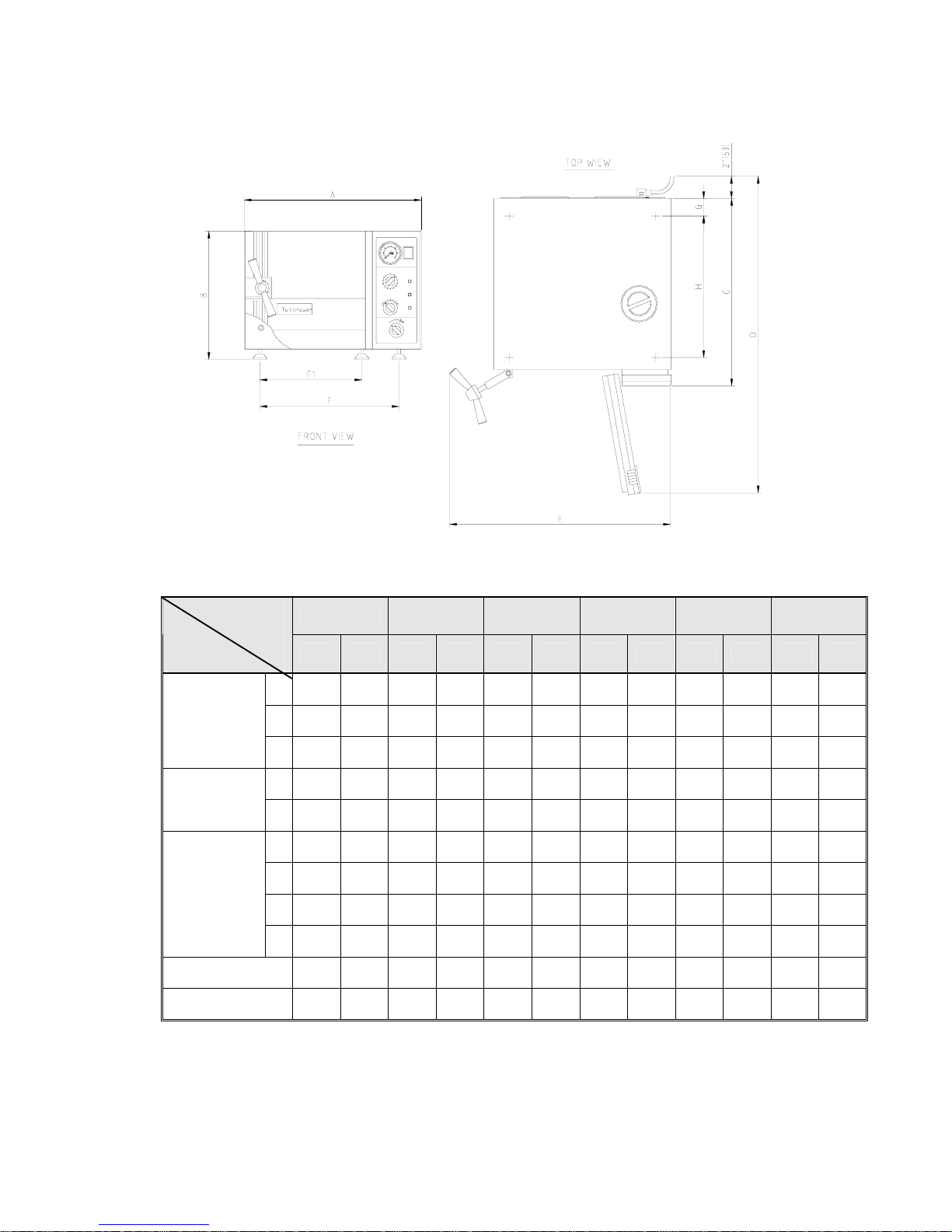
2.9 Dimensions
1730 2340 2540 3545 3850 3870
Model
Dimensions
Inch mm Inch mm Inch mm Inch mm Inch mm Inch mm
A 17.4 440 20.0 510 20.0 510 23.2 590 26.0 660 26.0 660
B 12.0 305 14.4 365 14.4 365 17.7 450 20.7 525 20.7 525
Overall
Dimensions
C 17.9 455 21.5 545 21.5 545 21.9 556 27.5 695 34.5 875
D 29.5 750 35.8 910 35.8 910 39.0 990 45.5 1155 53.0 1335
Maximum
dimensions
(door open)
E 22.0 560 25.8 655 25.8 655 29.7 755 32.0 815 32.0 815
F1 9.2 234 11.8 299 11.8 299 19.2 488 17.7 450 17.7 450
F 13.4 339 16.6 422 16.6 422 14.6 371 22.2 564 22.2 564
G 2.0 50 2.0 50 2.0 50 2.0 50 2.0 50 2.0 50
Distance
between
supporting
legs
F1-front legs
F -rear legs
H 12.4 315 15.8 400 15.8 400 15.2 386 21.8 555 30.5 725
Diameter 6.7 170 9.1 230 10 254 12.3 312 15.1 384 15.1 384
Depth 13.4 340 18.5 470 18.7 475 15.4 391 22.8 580 29.9 760

Page 8 of 63 Pages
Shipping
Volume
0.18 m
3
(6.35 cu.f.)
0.27m
3
(9.4 cu.f.)
0.27m
3
(9.4 cu. f.)
0.35 m
3
(12.4 cu.f)
0.63 m
3
(22.2cu.f.)
0.76m
3
(26.8cu.f)
Shipping
Weight
24.8 kgs.
(54.7 lbs.)
35.7 kgs.
(78.7 lbs.)
47.8 kgs.
(83.3 lbs.)
60 kgs
(132 lbs.)
89 kgs.
(196 lbs.)
102 kgs.
(225 lbs.)
full
2
3
4
10
15
No. of
standard
Cassettes
(Optional)
Half
2
2
3
4
No.
of trays
3
3
4
2
2
2
Tray dimensions
W X D X H
12 x 29.5 x 2 cm
(4.7" x 11.6" x 0.8")
17 x 41.5 x 2cm
(6.7" x 16.3" x 0.8")
17 x 41.5 x 2 cm
(6.7" x 16.3" x0.8")
25.6 x 40.8 x 2.5 cm
(10.1” x 16.1” x 1”)
19.8 x 40.8 x 2.5 cm
(7.8” x 16.1” x 1”)
28 x 50 x 2.5 cm
(11" x 20 " x 1" )
35 x 50 x 2.5cm
(14" x 20 " x 1")
28 x 67 x 2.5cm
( 11" x 26" x 1" )
35 x 67 x 2.5
(14" x 26" x 1")
Volume of
chamber
7.5 liters.
(2 US gal.)
19 liters.
(5 US gal.)
23 liters.
(6 US gal.)
34.4 liters
(7.8 US gal.)
65 liters.
(17US gal)
84 liters.
(22 US gal)
Chamber
dimensions
DIA x D
17 x 34 cm
(6.7" x 13.4")
23 x 47 cm
(9" x 18.5")
25.4 x 47.5cm
(10" x 18.7")
31.2 x 39.1
(12.3” x 15.4”)
38 × 58 cm.
(15" × 23" )
38x76 cm
(15" x 30")
2.10 Technical Specifications
Model
Specifications
1730
2340
2540
3545
3850
3870
Page 9 of 63 Pages
2.11 Electrical Data
Model
Sp
ecifications
1730 2340 2540 3545 3850 3870
Total power model 120V 8.8A 11.7A 11.7A ― ― ―
Total power model 230V 4.6A 6.0A 6.0A 10.4A 10.4A 13A
Heaters W 1050 1400 1400 1800 2400 3000
Protection against electrical shock Class I (IEC 60601-1)
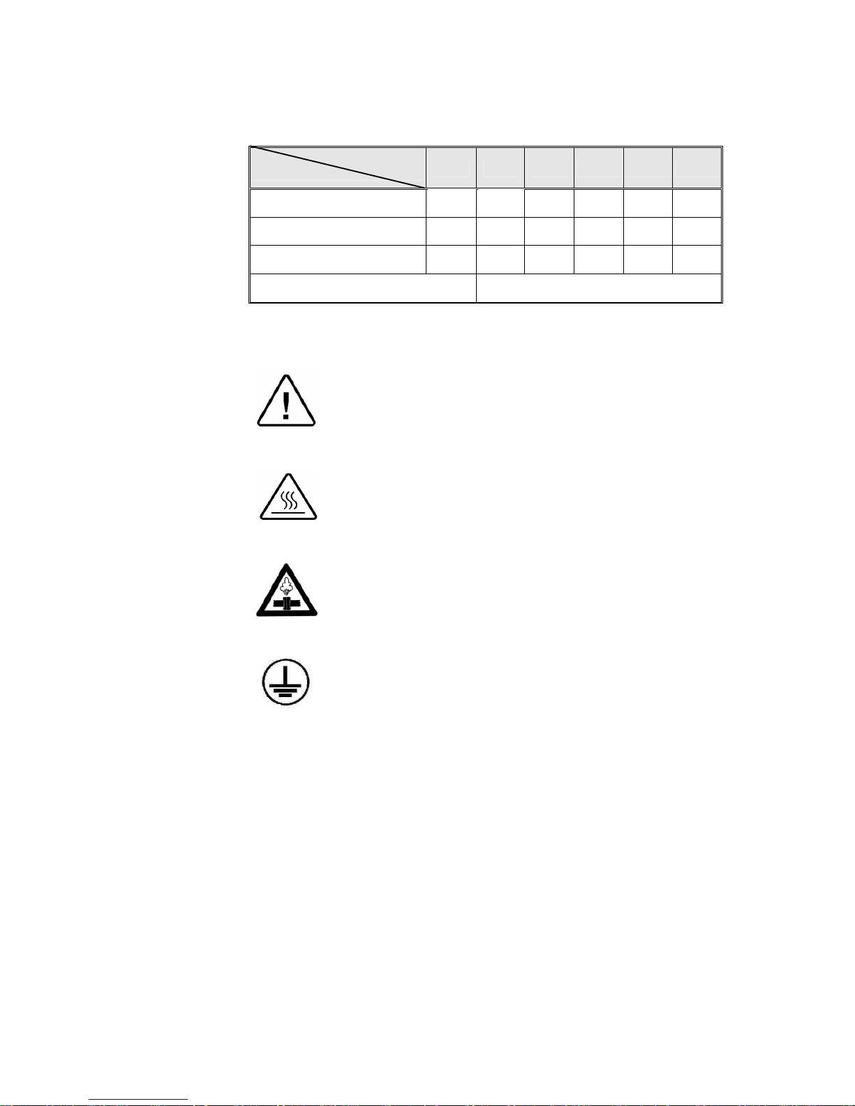
2.12 Symbol Description
Caution! Hot steam.
Caution! Consult accompanying documents
Caution! Hot Surface.
Ground
Page 10 of 63 Pages
FRONT VIEW
1. Front legs
2. Reservoir water drain valve.
3. Door tightening bolt
4. Door Micro-switch
5. Autoclave cover
6. Water reservoir cover
7. Water reservoir
8. Safety valve
9. Air trap jet
10. Pressure gauge
11. Timer
12. Pressure switch (B10) knob
13. Multipurpose valve
14. Heat indicator light
15. Dry indicator light
16. Power indicator light
17. Main power switch
Page 11 of 63 Pages
3. DESCRIPTION OF COMPONENTS
The item numbers refer to the front view in the previous page
3.1 Control Panel
Item
Description Operation
10.
PRESSURE GAUGE
0-60 psi, (0-4bar) indicates the chamber pressure.
11.
TIMER 0-60 min.
Sets the sterilization and drying cycles and
automatically switches off the power supply to
the heating elements when the times reaches “0”.
12.
PRESSURE SWITCH
Sets the sterilization temperature for each desired
material 221-274ºF, (105-134ºC). See page 18.
Position
1. FILL
Water flows from the water reservoir into the
chamber.
2. STE.
Valve closed to all directions.
3. EXH.&
DRY
Exhausts the steam from the chamber into the
water reservoir after the sterilization cycle is
finished.
13.
MULTI-PURPOSE
VALVE
4. “ 0 ”
Heating elements are disconnected, no cycle is in
progress.
14.
HEAT INDICATOR LIGHT
Lights to indicate that the heaters are activated.
They will shut off when the temperature reaches
the desired value.
15.
DRY INDICATOR LIGHT
Lights to indicate that drying cycle is in process.
16.
POWER INDICATOR LIGHT
Light to indicate that the main switch is on.
17.
MAIN SWITCH-
Main power switch, which supplies electric
power to the autoclave.
3.2 Other Components
Item
Description Operation
2.
WATER DRAIN VALVE
Enables the drainage of water from the reservoir.
7.
WATER RESERVOIR
Holds ample water for sterilization and also
serves as a steam condenser.
8.
SAFETY VALVE
Blows off when pressure in the chamber reaches
40psi (2.7Bar) in models 1730, 2340, 2540 and
37psi in models 3545, 3850, 3870. This type of
safety valve is A.S.M.E. approved (located in
water reservoir).
9.
AIR TRAP JET
Prevents air pockets in the chamber to ensure
adequate sterilization (located in the water
reservoir).
♦
SAFETY THERMOSTAT
Prevents over-heating during the drying stage.
♦
CUT-OUT THERMOSTAT
Cuts off the power in case of overheating if the
safety thermostat does not operate. This
thermostat does not reconnect automatically but
must be reset.

Page 12 of 63 Pages
4. INSTALLATION, PLACING AND LEVELING INSTRUCTIONS
Network
Network and connection should comply with the devices
consumption. It must comply with local installation and safety rules
and regulations. The voltage supplied to the device must comply
with the label ± 5%.
Caution:
The sterilizer must be placed on a rigid and leveled surface. The
stand must be able to hold the load of the device and loaded
material.
Note:
Make sure while placing the autoclave, to leave space around the
machine, to give the technician access to service the machine.
In order to avoid any injury by electrical hazard, it is mandatory for the
customer to have installed an earth leakage relay in the electrical board to
which the autoclave is connected.
This relay disconnects all the poles of the electrical power line in case of
accidental contact with the instrument metal enclosure, by the operator or
another person, leading to a dangerous leakage current.
Note: Keep the back and the right side of the autoclave approximately 1”
(25mm) away from the wall to allow for ventilation.
Connect the power cord to the socket on the rear side of the autoclave; plug it
into the supply socket.
4.1 leveling
The legs (2) of the autoclave are factory set for the autoclave to hold
this amount of water when the autoclave stands on a level surface (3).
To check the water level fill a beaker (4) with the recommended
quantity of water, pour the water into the chamber. The water must
reach the indicator groove (1) in front of the chamber.
1730 2340/2540 3545 3850 3870
300 ml.11 ozs. 350 ml.12 ozs. 400 ml.14 ozs. 500 ml.17 ozs. 650 ml.23 ozs.
If it is necessary, raise the front legs in order to get the proper amount
of water.

Page 13 of 63 Pages
4.2 Water quantity for a cycle
The amount of water in the autoclave chamber necessary for each
sterilization cycles as follows:
1730 2340/2540 3545 3850 3870
350
ml.
12
ozs.
450
ml.
16
ozs.
700
ml.
25
ozs.
850
ml.
30
ozs.
1000
ml.
35
ozs.
It is imperative to have the correct amount of water for proper
operation of the autoclave!
4.3 Lifting and Carrying
Caution:
Before moving the autoclave, make sure that the electric cord is
disconnected from the power source and that there is no pressure in
the chamber.
1. Disconnect the power supply cord.
2. Drain the water from the reservoir and vessel.
Lifting and carrying should be done by two people.
Do not drop the device!
4.4 Loading and Unloading the Device
Protective equipment and clothes should be implemented in accordance
to local and national regulations and/or rules!

Page 14 of 63 Pages
5. WATER QUALITY
The distilled or mineral – free water supplied to the autoclave should have the
physical characteristics and maximum acceptable level of contaminants
indicated in the table below:
Physical characteristics and acceptable contaminants levels in water,
for sterlizers
Evaporate residue
≤ 15 mg/l
Silica
≤ 2 mg/l
Iron
≤ 0.2mg/l
Cadmium
≤ 0.005 mg/l
Lead
≤ 0.05 mg/l
Rest of heavy metals
≤ 0.1 mg/l
Chloride
≤ 3 mg/l
Phosphate
≤ 0.5 mg/l
Conductivity
≤ 50 µs/cm
pH 6.5 to 8
Appearance Colourless, clean, without sediment
Hardness
≤ 0.1 mmol/l
Compliance with the above data should be tested in accordance with
acknowledged analytical methods, by an authorized laboratory.
Attention:
We recommend testing the water quality once a month. The use of water for
autoclaves that does not comply with the table above may have severe impact
on the working life of the sterilizer and can invalidate the manufacturer’s
guarantee.

Page 15 of 63 Pages
6. PREPARATION BEFORE STERILIZATION
The purpose of packaging and wrapping of items for sterilization is to provide
an effective barrier against sources of potential contamination in order to
maintain sterility and to permit aseptic removal of the contents of the pack.
Packaging and wrapping materials should permit the removal of air from the
pack, penetration of the sterilizing water vapor into the pack and removal of
the sterilizing vapor.
The basic principle determining the size, mass and contents of instrument and
hollowware packs is that the contents are sterile and dry immediately on
completion of the drying cycle and removal of the pack from the sterilizer
chamber.
Instruments to be sterilized must be clean, free from any residual matter, such
as debris, blood, pads or any other material. Such substances may cause
damage to the contents being sterilized and to the sterilizer.
1. Immediately after use, clean instruments thoroughly to dispose of any
residue.
2. It is recommended to wash instruments with an ultrasonic cleaner, using
detergent and mineral-free water.
3. Launder textile wraps prior to reuse.
4. After cleaning, rinse instruments for 30 seconds. (Follow manufacturer’s
instructions on the use of products for cleaning and lubricating
instruments after using the ultrasonic cleaner).
5. Materials, including materials used for inner wraps, shall be compatible
with the item being packed and the sterilizing method selected.
6. Do not place materials to be sterilized directly on the chamber’s wall.
Place the material only on trays, rack, etc.
7. Before placing an instrument into the sterilizer tray, make sure that
instruments which are not of the same metal, (stainless steel, carbon
steel, etc.) are separated and placed on different trays.
Note: Check manufacturer’s instructions for the sterilization of each
item.
8. In case carbon steel instruments are placed on stainless steel trays, the
trays should be lined with a towel or paper wrap before placing the
instruments on the trays. There should be no direct contact between the
carbon steel and the stainless steel trays.
9. All instruments must be sterilized in an open position.
10. Use single-use wraps once only and discard after use.

Page 16 of 63 Pages
11. Verify that the packaging method is in accordance with good practice
approach and the packaging materials are in accordance with the
applicable standards (e.g. EN868 series).
12. Place a sterilization indicator strip in each tray.
13. Place instruments with ratchets opened and unlocked or clipped on the
first ratchet position.
14. Disassemble or sufficiently loosen multiple-part instruments prior to
packaging to permit the sterilizing agent to come into contact with all
parts of the instrument.
15. Tilt on edge items prone to entrap air and moisture, e.g. hollowware, so
that only minimal resistance to air removal, the steam passage and
condensate will be met.
16. Load items within the boundaries of the tray so that they do not touch
the chamber walls, or fall off when the loaded car is inserted into the
autoclave.
17. The operator may use racks to allow for adequate separation of packaged
instruments.
18. Load trays loosely to capacity.
19. Once a week, use a biological spore test indicator in any load to make
sure sterilization is performed.
20. Make sure that all instruments remain apart during the sterilization cycle.
21. Empty canisters should be placed upside-down, in order to prevent
accumulation of water.
22. Allow a distance of approximately 2.5 cm (1”) between trays to permit
steam circulation.
23. Wrapped Instruments
Wrapped instruments should be packed in material that promotes drying
such as autoclave bag, autoclave paper, and muslin towels.
It is highly recommended to utilize the Tuttnauer Pouch Rack. This
rack allows the operator to place pouches on their side, thus increasing
the capacity of the autoclave significantly and promoting better drying of
the instruments. Contact your dealer for details.
Note:
A table “Suitability of steam sterilization processes for various goods and
method of packing” is added to the accompanying documents.
Pouch Rack

Page 17 of 63 Pages
24. Packs
1. Place packs upright on trays, side by side.
2. Packs should not touch the chamber walls.
3. Pack instrument sets in a manner that prevents damage to delicate
items.
4. Pack hollowware sets so that all openings face the same direction
and so that the contents cannot move inside the pack.
5. Load packs of folded operating room drapes with layers vertical,
allowing air to be removed from the packs rapidly.
6. Do not place packs of hollowware and trays of instruments above
textile packs or soft goods in order to avoid wetting caused by
condensation from items above.
7. Load items packed in flexible packaging materials on edge with
paper to laminate, or flat with the paper surface downwards.
Note:
The manufacturer’s recommendations shall be observed, concerning
the sterilization data for each type of material.
25. Tubing
When placing in a tray, make sure that both ends are open, without sharp
bends or twists.
Wrong
Right

Page 18 of 63 Pages
26. Liquids
Use only heat-proof glass, filled to 2/3 capacity. Ensure that the glass
container is covered, but not sealed to prevent pressure build-up.
Note: A table of suitability steam sterilization process for various
goods and methods of packing is included with accompanying
documents.
Liquids
 Loading...