

Page 1

TECHNICIAN
MANUAL
Laboratory Vertical Steam Sterilizers
models
2540, 3150, 3170, 3850, 3870, 5050, 5075
ELV Standard Autoclave
ELVC
ELVPRC
Cat. No. MAN205-0060000EN Rev.AA
Tuttnauer Europe B.V., Hoeksteen 11 4815 PR P.O. Box 7191 4800 GD Breda, The Netherlands
Tel: 31 (0) 765423510, Fax: 31 (0) 765423540
Including Preparation for Fast Cooling System
Including Fast Cooling System
Page 2

Page 3

TABLE OF CONTENTS
PARAGRAPH PAGE NO.
1. INTRODUCTION
2. SYMBOL DESCRIPTION
3. INSTALLATION INSTRUCTIONS
3.1 Installation Site.................................................................................................6
3.2 Connection of the pressure regulator................................................................6
4. TESTS
4.1 Installation Tests.............................................................................................11
4.2 Periodical Tests...............................................................................................11
5. WATER QUALITY
5.1 Water for Generating Steam ...........................................................................12
5.2 Water for the Vacuum pump and drain cooling..............................................12
5.3 Reverse Osmosis..............................................................................................12
6. DESCRIPTION OF THE CONTROL SYSTEM.
6.1 Digital Board DIG - T2...................................................................................13
6.2 Analog Board ANL-T2....................................................................................15
6.3 AC - Board - AC-T1........................................................................................16
7. CALIBRATION OF TEMPERATURE AND PRESSURE
7.1 Method of Calibration:....................................................................................17
7.2 Temperature Calibration Procedure...............................................................18
7.3 Pressure Calibration Procedure......................................................................20
.......................................................................................................................11
....................................................................................................4
......................................................................................4
.....................................................................5
................................................................................................12
............................................13
............................17
8. TEST POINTS
9. SOFTWARE PROGRAMMING PROCEDURES
9.1 General ...........................................................................................................22
9.2 Changing Cycle Parameters............................................................................22
9.3 Resetting the Autoclave...................................................................................30
9.4 Test Mode........................................................................................................30
10. REPLACING ELEMENTS
10.1 Safety Tests after Repair .................................................................................31
10.2 Replacing the Circuit Breaker.........................................................................32
10.3 Replacing the Safety Valve..............................................................................33
10.4 Replacing the Door Gasket .............................................................................34
10.5 Replacing the electronics board (control panel)..............................................35
10.6 Replacing the Electronics Box........................................................................36
10.7 Cut-Out Thermostat........................................................................................39
10.8 Replacing Heating elements............................................................................40
10.9 Safety Door Locking System for models 2540, 3150, 3170, 3850, 3870 ..........41
10.10 Safety Door Locking System for models 5050, 5075 .......................................43
10.11 Disassembling and Assembling the Door Cover, Models 2540, 3150, 3170,
3850, 3870.......................................................................................................44
........................................................................................................21
............................................22
..................................................................................31
Page 1 of 132 Pages
Page 4

TABLE OF CONTENT (Cont.)
PARAGRAPH PAGE NO.
10.12 Disassembling and Assembling the Door Cover, Models 5050, 5075..............46
10.13 Replacing the locking microswitch (Models 5050, 5075)................................49
10.14 Replacing the safety-opening valve (Models 5050, 5075)................................50
10.15 Replacing the “DOOR CLOSED” microswitch (Models 5050, 5075).............51
10.16 Replacing the solenoid lock (Models 5050, 5075)...........................................52
10.17 Cleaning and Replacing the Water Level Electrodes......................................53
10.18 Replacing the Printer......................................................................................54
10.19 Replacing the Door Switch (models 2540, 3150, 3170, 3850, 3870)................56
10.20 Replacing the Locking Device (models 2540, 3150, 3170, 3850, 3870)...........57
10.21 Replacing the Plunger or Coil of the BACCARA Solenoid Valve...................58
11. IN-OUT TEST
12. TROUBLESHOOTING
12.1 Displayed Messages and Reference to Trouble Shooting................................60
12.2 Pre-process malfunction .................................................................................61
12.3 In Process Malfunction...................................................................................67
12.4 Mechanical malfunction.................................................................................86
13. LIST OF SPARE PARTS
14. PRESSURE VS TEMPERATURE FOR SATURATED STEAM
15. XPCS Manual
16. VALVES NUMBERING
........................................................................................................59
.........................................................................................60
.....................................................................................87
.................97
.......................................................................................................101
.....................................................................................114
Page 2 of 132 Pages
Page 5

TABLE OF CONTENT (Cont.)
DRAWINGS PAGE NO.
Rear View Model 2540........................................................................................................... 7
Rear View Models 3150, 3170 ............................................................................................... 8
Rear View Models 3850, 3870 ............................................................................................... 9
Rear View Models 5050, 5075 ............................................................................................. 10
Control System Block-Diagram........................................................................................... 13
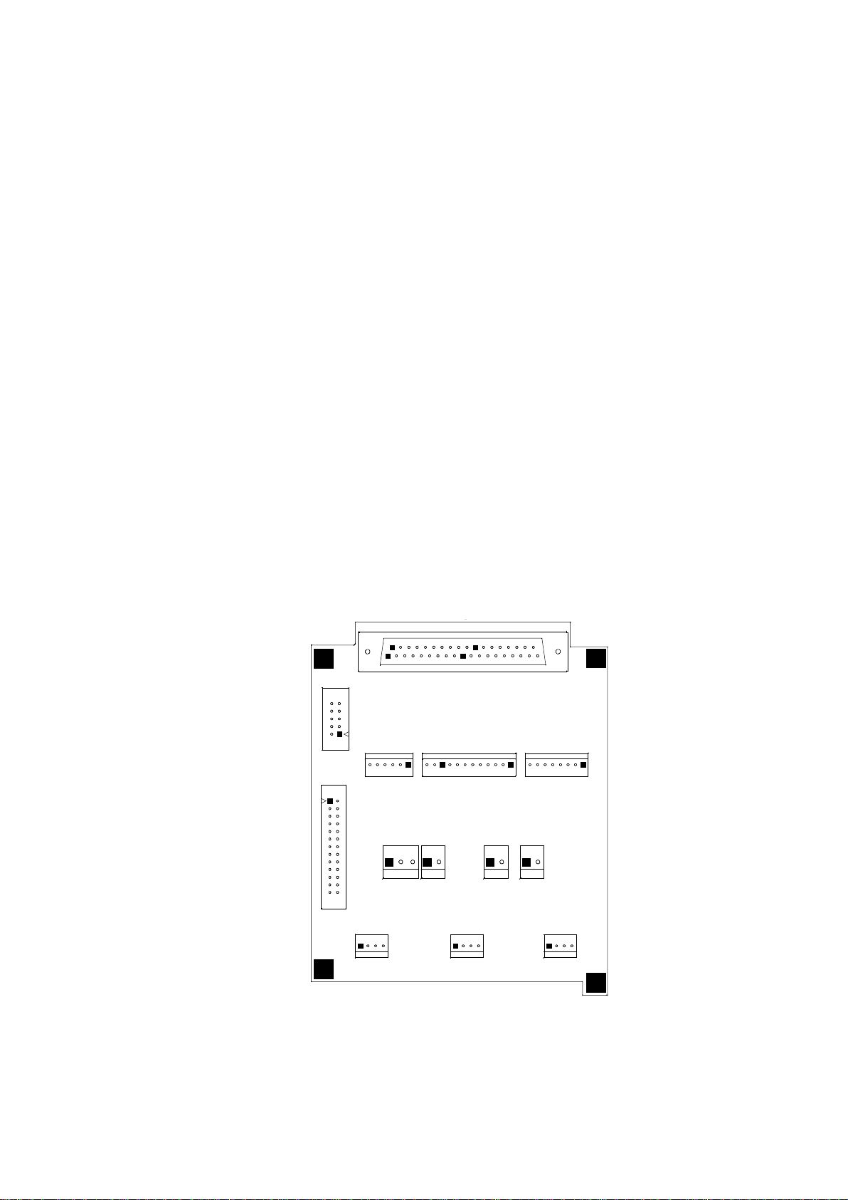
DIG- T2 Board .................................................................................................................... 14
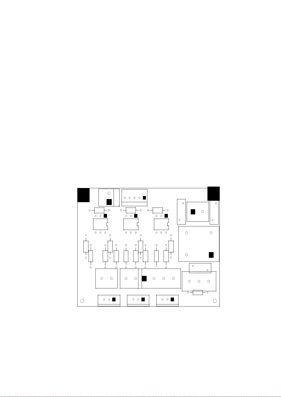
ANL - T2 Board................................................................................................................... 15
AC-T1 Board ....................................................................................................................... 16
Vessel Assembly Models 2540, 3150, 3170, 3850, 3870....................................................... 92
Vessel Assembly Models 5050, 5075.................................................................................... 93
Door Tightening Bolt – Assembly........................................................................................ 94
Door Locking System........................................................................................................... 95
Water Outlet Strainer .......................................................................................................... 96
Piping Drawing: 2540 ELV &, ELVPRC.......................................................................... 116
Piping Drawing: 2540 ELVC............................................................................................. 117
Piping Drawing: 3150, 3170, 3850, 3870 ELV & ELVPRC .............................................. 118
Piping Drawing: 3150, 3170, 3850, 3870 ELVC................................................................ 119
Piping Drawing: 5050, 5075 ELV & ELVPRC.................................................................. 120
Piping Drawing: 5050, 5075 ELVC................................................................................... 121
Electrical Wiring Diagram For Autoclave Model 2540 ELV ............................................ 122
Electrical Wiring Diagram for Autoclave Models 3150/3170 ELV ................................... 123
Electrical Wiring Diagram for Autoclave Models 3850/3870 ELV 3x400V ...................... 124
Electrical Wiring Diagram for Autoclave Models 3850/3870 ELV 3x230V ...................... 125
Electrical Wiring Diagram for Autoclave Models 3850/3870 ELV 3x208V ...................... 126
Electrical Wiring Diagram for Autoclave Models 5050/5070 ELV 3x400V ...................... 127
Electrical Wiring Diagram for Autoclave Models 5050/5070 ELV 3x230V ...................... 128
Electrical Wiring Diagram for Autoclave Models 5050/5070 ELV 3x208V ...................... 129
Switch Box Wiring Diagram.............................................................................................. 130
Open Switch Box............................................................................................................... 131
Closed Switch Box............................................................................................................. 132
Page 3 of 132 Pages
Page 6
1. INTRODUCTION
This manual, together with the operator’s manual, forms the complete edition of the
Operation and Maintenance instructions. This manual is intended for the use of the
technician. It is forbidden for unqualified and unauthorized personnel to service the
autoclave in accordance with the instructions in this manual. Any unauthorized service
may result in the invalidation of the manufacturer’s guarantee.
The qualified technician shall be an authorized electrician with the right qualifications
in electronics and shall be familiar with the local technical/electrical regulations.
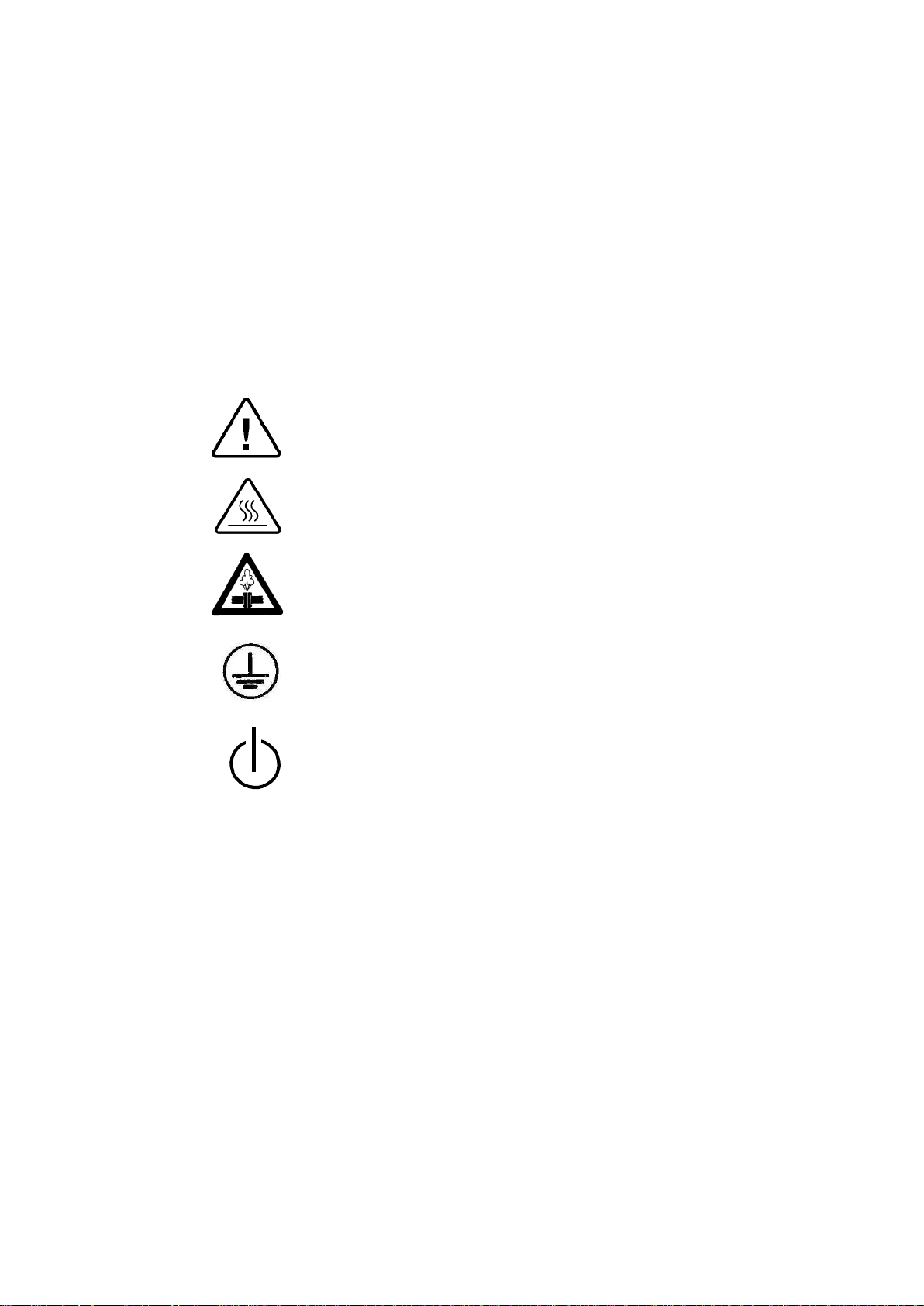
2. SYMBOL DESCRIPTION
Caution! Consult accompanying documents
Caution! Hot surface.
Caution! Hot steam.
Protective earth (Ground)
Stand by
Page 4 of 132 Pages
Page 7
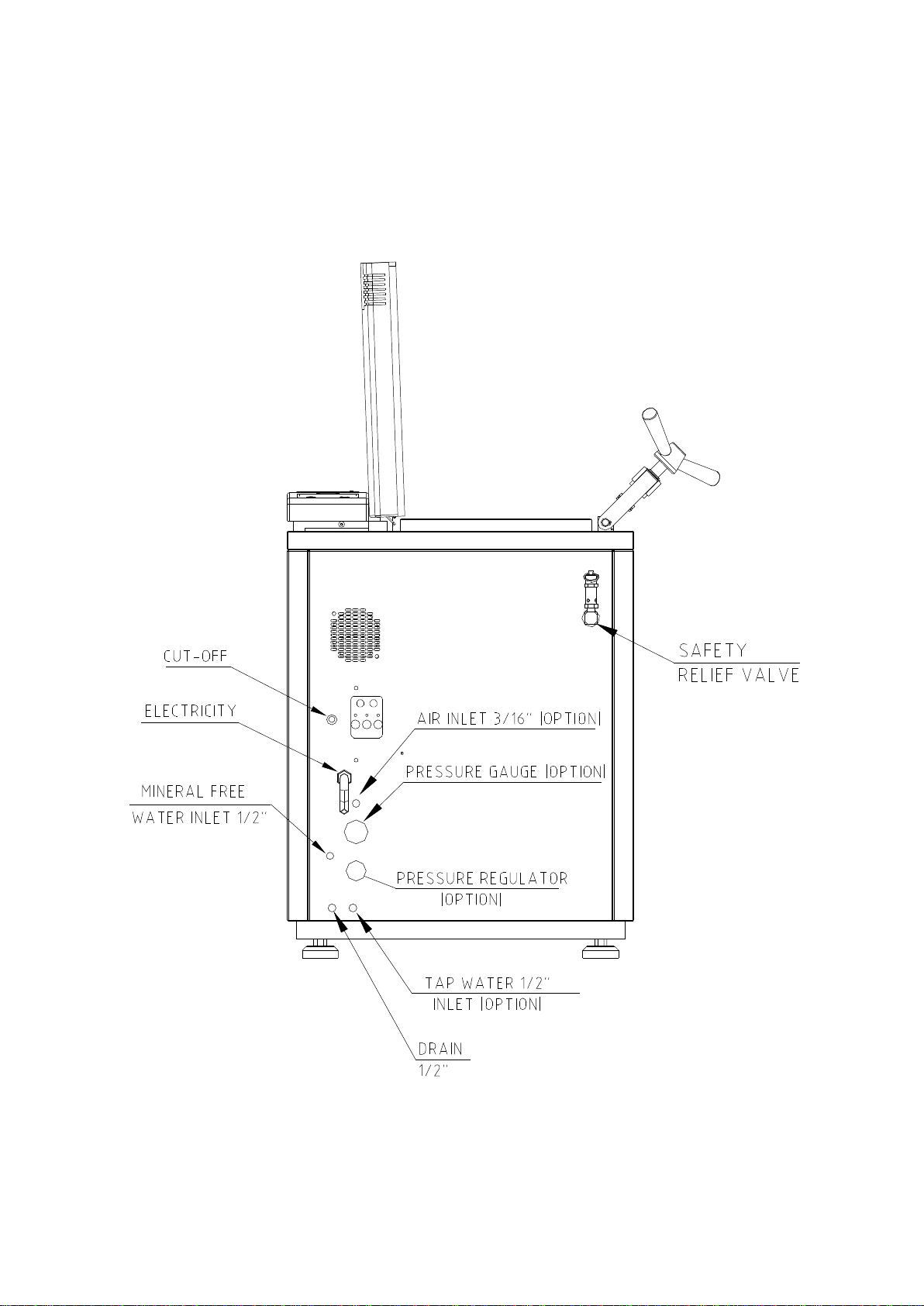
3. INSTALLATION INSTRUCTIONS
Recommended
For all the ELV models, the following utilities have to be connected (Refer to the
drawing below ‘Rear View’ of the autoclave).
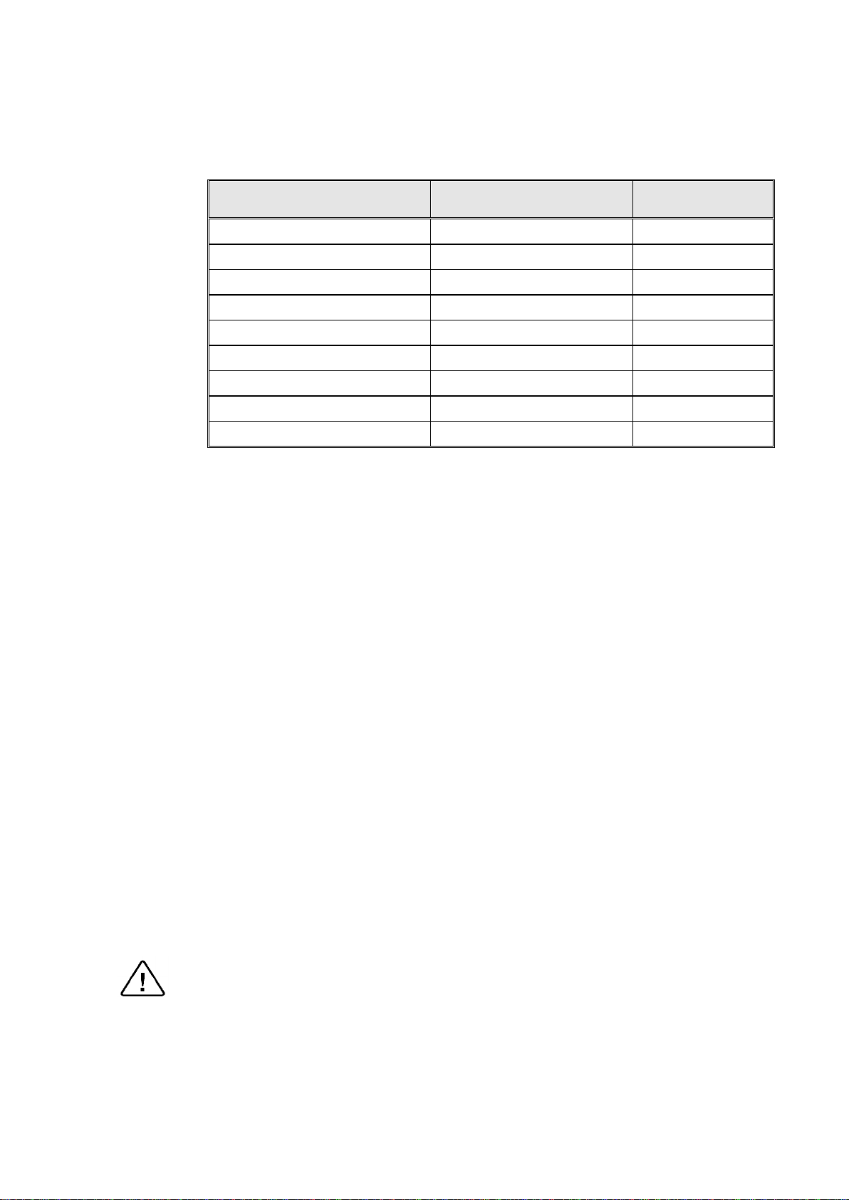
Power outlet, as detailed in the table below:
Model Power
2540
3150/70
3850/70
3850/70
3850/70 with switching box
3850/70, 5050/75
5050/75
5050/75
5050/75 with switching box
If the autoclave is a 3 phase 3870, 5050 or 5075 autoclave and has to be connected
to a one phase power network, 1 x 230V, 50/60Hz., connected the 1ph 230V
power source to the supplied switch box that has a 1 phase input (from the power
source) and a 3 phase output (to the autoclave). See details at the end of this
manual.
The power network must be protected by a current leakage relay.
Mineral-free water having a conductibility lower than 15µs (microsiemens),
through a 1/2” flexible hose.
1Ph, 230V/50/60Hz 20A
1 or 2 Ph, 230V/50/60Hz 25A
3 Ph, 208V/50/60Hz 25A
3 Ph, 230V/50/60Hz 25A
1 or 2 Ph, 230V/50/60Hz 30A
3 Ph, 400V/50/60Hz 20A
3 Ph, 208V/50/60Hz 30A
3 Ph, 230V/50/60Hz 30A
1 or 2 Ph, 230V/50/60Hz 45A
Circuit Breaker
To obtain water quality meeting requirements a deionization column or reverse
osmosis apparatus can be installed. The water must be delivered at a pressure of 23bar. A pressure reducer shall be installed at the water source outlet as instructed
below.
For fast cooling (if this option is provided):
Feed water from the water network, pressure 2-3bars, connected through a 1/2”
pipe. A pressure reducer shall be installed at the water source outlet as instructed
below.
Compressed air, from a mobile compressor or compressed air network at pressure
3-4 bars, will be set at 1.6-2bars at the autoclave inlet is to be connected by a
flexible conduit of 3/16”.
The air must be of instrumental quality filtered at 5µ and free of humidity and oil
drops.
Drain connected by 1/2” pipe, located at the rear of the unit. The chamber exhaust
and coolant water is evacuated to an open waste funnel. The drainage piping must
be heat resistant, to 80ºC, non-continuous flow.
Attention:
Connection of water system to the autoclave must be performed through "BACK
FLOW PREVENTION SYSTEM" installation as per EN 1717:2001 regulations
and local regulations.
.
Page 5 of 132 Pages
Page 8
54321
6
3.1 Installation Site
Pressure Regulator, Water, In
-
Line,
1. Install the autoclave according to the following guidelines:
2. Place the autoclave on the floor. Verify that the surface is leveled.
3. All utility supplies must be prepared in accordance with requirements,
before autoclave installation e.g. mineral-free and tap water, compressed
air, one or three-phase power network, connection to the drain of the
building.
5. Leave the space free around the autoclave for maintenance and service
requirements.
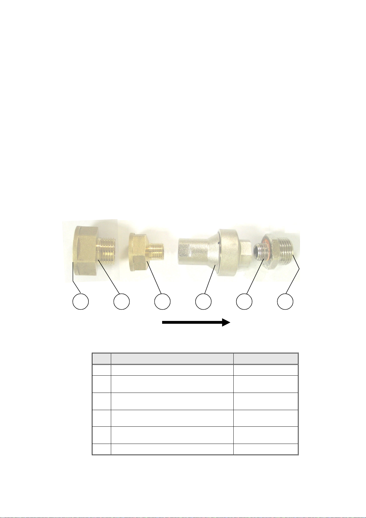
3.2 Connection of the pressure regulator
This paragraph refers to the pressure regulator of the feed water and to the
pressure regulator of the mineral free water.
1. Attach the pressure regulator to the facility's water outlet.
2. Connect the supplied flexible hose to the pressure regulator's assembly
outlet and to the autoclave's water inlet.
3. Verify that the pressure regulator is in right direction. The flow direction is
indicated by an arrow stamped on the pressure regulator.
4. Verify that water flows freely in the feed water and in the mineral free
water lines.
FLOW DIRECTION
No. Description Cat No.
1 Side of water supply source N/A
Reducer, Female 3/4" BSP to Male
2
1/2" BSP, Brass
Reducer, Female 1/2" BSP to Male
3
1/4" BSP, Brass
4
with Strainer, 1/4 x 1.5 bar
Fitting, Adaptor, M 1/2" BSP x M
5
1/4" BSP, Brass Ni plated
FIT100-0424
FIT100-0425
GAU029-0059
PNE100-0042
6 Side of flexible hose (to autoclave N/A
Page 6 of 132 Pages
Page 9
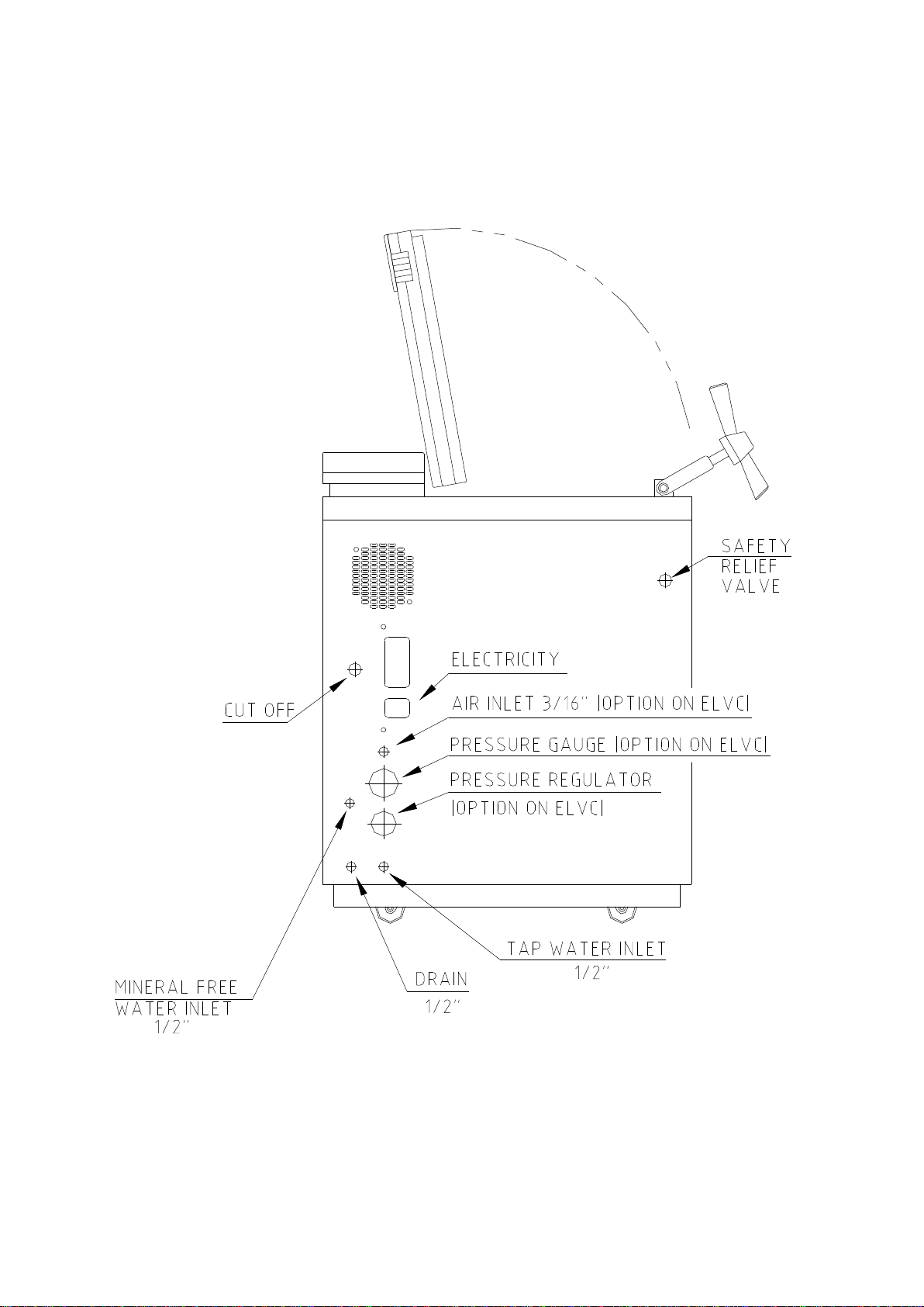
REAR VIEW MODEL 2540
Page 7 of 132 Pages
Page 10
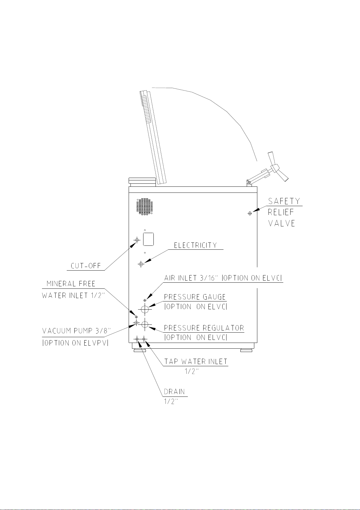
REAR VIEW MODELS 3150, 3170
Page 8 of 132 Pages
Page 11
REAR VIEW MODELS 3850, 3870
Page 9 of 132 Pages
Page 12

REAR VIEW MODELS 5050, 5075
Page 10 of 132 Pages
Page 13
4. TESTS
4.1 Installation Tests
The service technician shall perform the following preliminary checks
before operating the autoclave:
a. Integrity Check
b Leveling Check
c. Leakage current test
d. Continuity Check
At this stage operate the autoclave and continue with the tests:
e. Safety Check
f. Programs Check
g. Validation
After the above steps are performed, the autoclave is ready for operation.
Perform a visual check to verify that there are no dents, scratches,
broken gauges, etc.
Check that the autoclave is leveled.
Check the precise operation of the earth leakage relay.
Check the continuity of the grounding connection.
Check the safety elements; safety valve and the door locking mechanisms.
Run basic programs of the autoclave and check the operation
sequences, the sterilization parameters etc.
Validate the sterilization cycles, taking in consideration the interface of
packaging/goods/autoclave.
4.2 Periodical Tests
PERIOD TEST
2
months
6
months
Test the safety valve by operating it
Remove the cover of the autoclave, tighten the screws of the heaters and
the electrical connections at the heaters, valves and connectors inthe
control box.
Check the continuity of the grounding connections.
Check the temperature and pressure calibration.
Perform validation of the autoclave.
Check the precise operation of the earth leakage relay.
Check that the autoclave is leveled.
Check the safety elements; safety valve, safety and cut-off thermostats
Year
door locking mechanisms.
Run basic programs of the autoclave and check the operation sequences,
the sterilization parameters etc.
Check the water reservoir, piping, plastic parts and electric wires.
Check and tighten the piping joints to avoid leakage.
Check and tighten all screw connections in the control box, heaters and
valves and instrumentation.
Observe the closing device for excessive wear
.
5 years Observe the closing device for excessive wear
Safety tests (pressure vessel, efficiency, electrical) shall be performed in accordance
with local rules or regulations, by an authorized inspector.
Only an authorized technician shall perform the 6-months and yearly tests!
Page 11 of 132 Pages
Page 14

5. WATER QUALITY
5.1 Water for Generating Steam
The distilled or mineral – free water supplied to the sterilizer shall be according
to the table below:
Physical Characteristics and Maximum acceptable contaminants levels
Element Condensate – allowable content
in steam for sterilizers
(According to EN 13060:2004).
Silicium oxide. SiO
2
≤0.1 mg/kg
Iron ≤0.1 mg/kg
Cadmium ≤0.005 mg/kg
Lead ≤ 0.05 mg/kg
Rest of metals except iron,
cadmium, lead
≤0.1 mg/kg
Chloride (Cl) ≤0.1 mg/kg
Phosphate (P2O5) ≤0.1 mg/kg
Conductivity (at 20°C) ≤3 μs/cm
pH value (degree of acidity) 5 to 7
Appearance Colourless clean without sediment
Hardness (Σ Ions of alkaline earth) ≤0.02 mmol/l
Compliance with the above data should be tested in accordance with
acknowledged analytical methods, by an authorized laboratory.
Attention:
We recommend testing the water quality once a month. The use of water that
do not comply with the table above may have severe impact on the working
life of the sterilizer and can invalidate the manufacturer’s guarantee.
5.2 Water for the Vacuum pump and drain cooling
The feed water supplied to the liquid ring vacuum pump must meet the
following requirements:
Hardness: 0.7 - 0.2 mmol/l.
Water temperature: shall not exceed 15°C.
Note:
The use of heavy scaled water for the vacuum pump cooling, can cause
blocking of the rotor and put the pump out of operation. This invalidates the
guarantee for the vacuum pump.
5.3 Reverse Osmosis
A Reverse Osmosis system may be used to improve the quality of the water
used to generate steam in the autoclave chamber. The use of mineral free will
contribute to better performance and longer life of the autoclave.
Page 12 of 132 Pages
Page 15
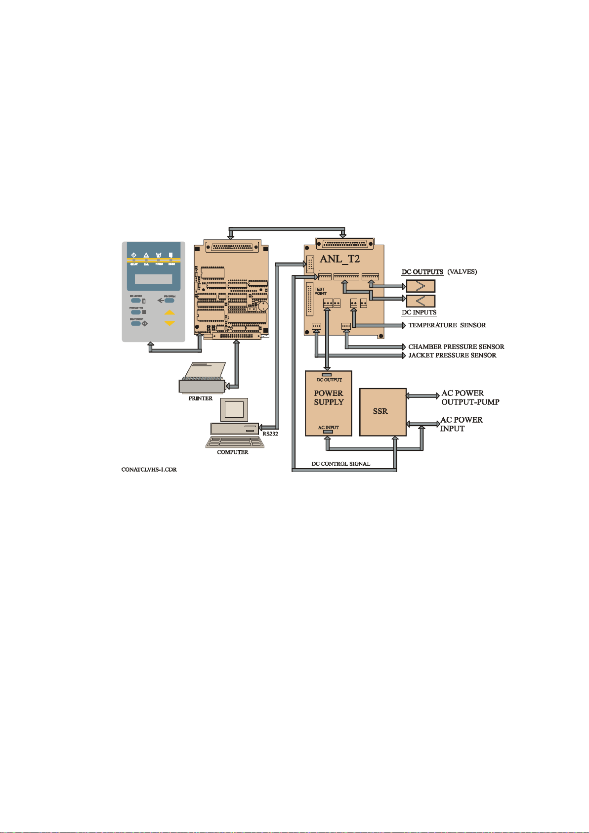
6. DESCRIPTION OF THE CONTROL SYSTEM.
1
JP8
(See CDR Control diagram).
The control system is based on 3 electronic boards designed according to the autoclave
requirements, the digital board DIG-T2 containing the micro-controller memories,
buffers and digital ICs and the analog board ANL-T2 which performs the processing
of signals coming from the sensors and switches. The AC-T1 board consists of filters
and AC drivers. DC voltages 12V and 5V, supplied by a switching type power supply,
powers the 3 electronic boards.
CONTROL SYSTEM BLOCK-DIAGRAM
SKT
20
1
DIG-T2 BOARD
C2
+
U12
R3
C9
U8
R2
U16
R1
U11
U14
C5
U21
U17
DIG T3
1
U3
C3
+
RP1
U15
R9
U22
97-05
C24
C25
D1
C15
8
C23
JP3
C22
U1
2
DS1
1
PLUG
37
JP1
19
C7
U18
C4
R4
U4
C16
C17
Q1
Y1
BZ1
U19
C6
34
33
20
1
P1
1
JP7
JP2
JP3
1
JP12
1
37
19
JP1
12
1
JP6
JP5
JP4
1
1
1
JP9
JP10
1
The system is provided with communication interfaces RS 232 to PC and to parallel
printer.
6.1 Digital Board DIG - T2
— The digital board is connected to the keypad panel, to the parallel printer
and to the analog board ANL-T2.
— The board contains the micro-controller (U15) type 80C32 that runs the
software program of the system.
— On the board, are three types of memories:
1) EPROM memory (U17), part no. 27512 storing the program codes.
2) RAM memory (U21) with a capacity of 32KB for the temporary data
during the running of the program.
3) EPROM memory (U22) that is a fixed serial memory with an
electrical writing and erasing.
— This EPROM serves as a non-volatile memory, enabling the system to
change follow-up tables during running of program codes, and ensuring
this data is not lost in case of power failure.
— The board contains an optimal Real Time Clock (U12), which serves as a
clock to the system, including a back-up battery, which ensures the clock,
runs continuously even when the autoclave is not powered.
Page 13 of 132 Pages
Page 16

This component is optimal because it is related to the operation of the
BZ
1
1
RP
8
1
+
printer, which is also an optional item.
— The board contains a watchdog, which detects any faulty situation in the
running program code. It performs an automatic reset of the microcontroller and stops all the commands to avoid an uncontrolled activation
of any of the heating elements or the valves.
— The board functions as an MMI (Man-Machine Interface). It is connected
to a LCD display of two rows with 16 characters on each row and to the
following light indicators:
— START (autoclave in process),
— FAIL (the process failed),
— WATER (no water in the reservoir),
— DOOR (the door is not closed).
A keyboard connected to the digital board, serves as a control panel containing
the command and programming keys.
— The digital inputs and outputs are transferred to the system, as follows:
— Through the digital board to the analog board by means of buffers
74HC377.
— RS232 interface is performed on the board by the U13 component, the
signal is transmitted to the communication connector located on the ANLT2 board.
— The printer is connected directly to this board, connector DS1 enables to
connect the DPU-20 printer manufactured by SEIKO.
The printer receives the data and the supply voltage directly from this
connector.
The layout of the DIG-T2 board components is provided below
DIG- T2 BOARD
SK
20
R8
JP 3
DIG
U1
C1
U1
C9
U1
U1
C2
R7 R6
C1
C2
C2
C2
DS
C1
+
C2
R3
R2
R1
C5
U2
U1
H2
97 -0 5
1
C1
U5
U1
C1
JP
C8
U 7
U8
U1
U3
C3
RP
U1
R9
U2
D
C1
2
1
U1
37
R5
R1
+
C1
U6
C4
U4
C1
Y1
JP 1
19
C1
C2
U2
R4
C1
C2
R1
R1
U2
C7
U1
Q 1
U1
C6
34
33
Page 14 of 132 Pages
Page 17
6.2 Analog Board ANL-T2
The analog board contains the drivers of the valves, heaters and pump. It
contains the sensors circuits connected to the control system, and serves as a
junction to the autoclave connections.
The input is 12VDC & 5VDC and the output is for all the signals to the
autoclave.
— The power supply provides the DC voltages 12V and 5V through the
connector JP3 to the board and further to the DIG-T2 board.
— The computer is connected to the board through the connector P1, by
RS232 interface.
— The analog and digital inputs, from the temperature sensor, electrode door
switch, etc. are connected through connector JP6, the conversion circuits
of the sensors are located on this board.
— The pressure sensor MPX2200 that measures the chamber pressure is
connected to the board through connector JP8, to the conversion circuit of
the sensor that is located on this board.
— The analog to digital conversion circuit A/D (U5) and the analog
multiplexer (U6) for 8 analog inputs (temperature, pressure, and electrode)
are located on this board and transfer digital signal to the DIG-T2 board.
— All the drivers and power circuits to the solenoids (valves, door locking)
are included on this board.
Layout diagram of the ANL-T2 is provided below.
ANL - T2 BOARD
PLUG
P1
JP2
JP12 JP8
1
ANL T1 BOARD
20
1
JP1
12 1 1
1
JP7
JP3
1
1
JP5
JP4
1
JP9
1
37
19
JP6
JP10
1
JP11
1
Page 15 of 132 Pages
Page 18
6.3 AC - Board - AC-T1
This board receives command signals from ANL-T2 board designated to
activate AC devices. It converts them to AC mode.
The AC-T1 board provides AC filtering for the power supply to the control
system and protection from sharp current fluctuations.
The AC-T1 board includes:
— AC drivers for the AC devices (pump, heaters, etc.) up to 6A.
— AC - input connector JP3.
— Filter circuit based on L1C5, the power transfer from the filter to power
supply via JP2.
— Spike protection - RV1÷3.
— Three - 230/115 VAC output channels, triac control circuit.
Q1 - 16Amp - JP4/1,2
Q2 - 8 Amp - JP7/1
Q3 - 8 Amp - JP7/2
AC-T1 BOARD
(JP3,JP4,JP7 ON THE BOTTOM SIDE OF THE BOARD)
U3
R12
JP5
R9
C3
R11
Q3
1
R10
R8 C2
JP7
U2
JP1
R5
R6
R7 C1
JP4
1
Q2
R4
1
R1
U1
R3
Q1
RV3 RV2
JP2
R2
L1
JP6
JP3
C5
ETYPEAC-97
CAT TECH.
RV1
Page 16 of 132 Pages
Page 19
7. CALIBRATION OF TEMPERATURE AND PRESSURE
a X
Y
310
100
7.1 Method of Calibration:
The calibration of temperature and pressure is performed digitally.
The temperature and pressure measuring circuits are designed with components
having 1% accuracy.
The temperature circuit is linear and has an output of 100mV÷2400mV for a
temperature range 20°C÷150°C.
The pressure circuit is also linear and has an output of 100mV÷2400mV for a
pressure range 0÷400 kPa.
The measuring at the A/D is limited for values higher than 2400mV or below
100mV.
It is obvious that although the accuracy of the circuit components is 1%, the
sum deviation may reach 5%. Therefore calibration is necessary.
The system has a non-volatile memory in which the offset and gain data of the
sensors are stored.
Calibration is performed by use of the keyboard (or the communication port for
computer use).
Following is a description of the calibration of temperature and pressure using
the keyboard. The calibration procedure is identical to all autoclave models.
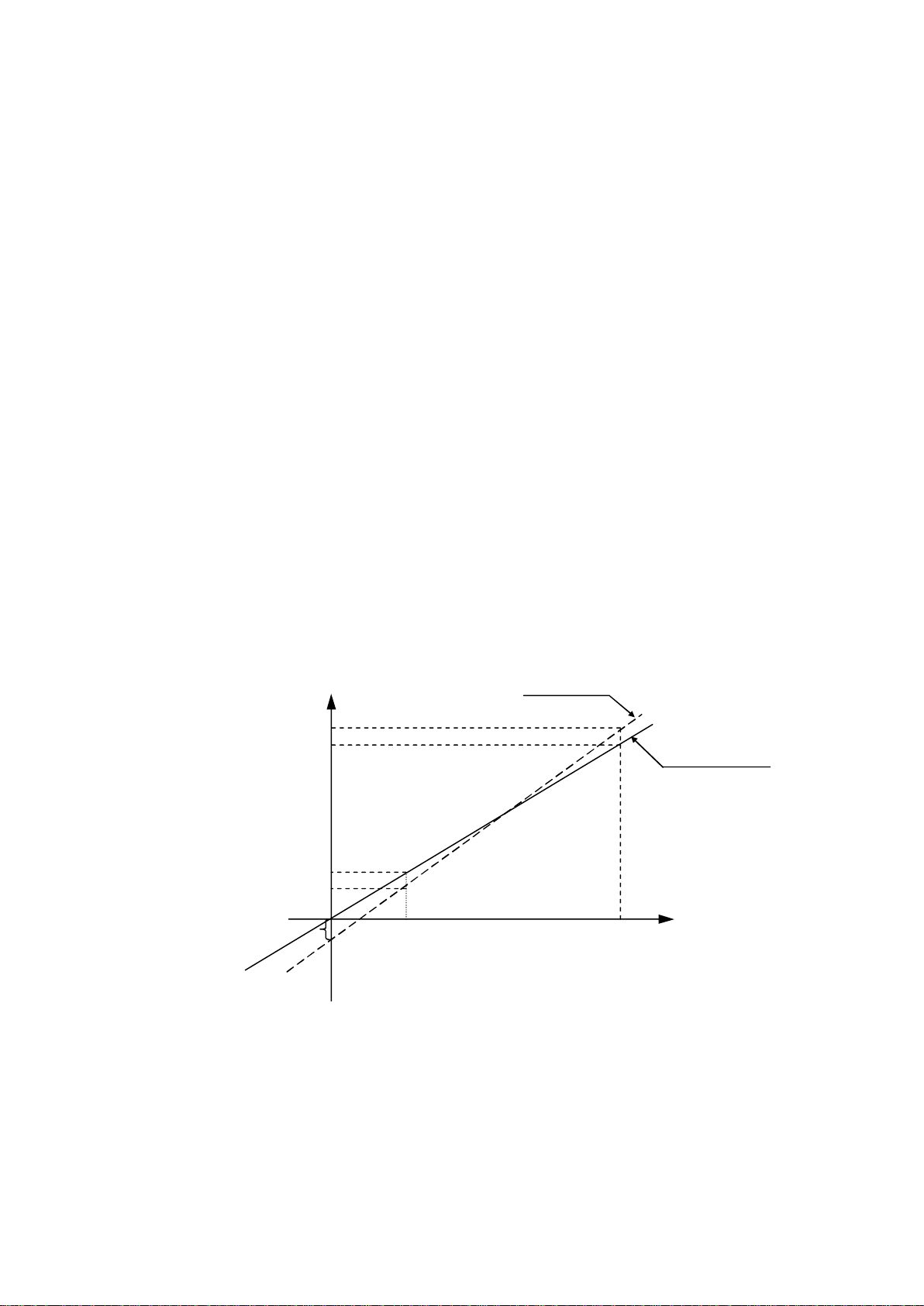
Definition of Gain and Offset:
Every straight line can be defined by the equation ax+b=y. “a” is the deviation
from y=0 and “b” is the slope of the line. In our case a=Gain and b=Offset.
The system is based on calculation of offset and gain of two points as in the
following example
If the actual measured pressures are 100 kPa & 300 kPa and the displayed
pressure are 90 kPa & 310 kPa respectively, the ‘input Vs pressure” graph will
be as follows.
READ
300
90
PRESURE
V
1
INPUT FROM SENSOR
V
2
ACTUAL
The calibration method enables to input this data into the system in order to
perform automatic correction of OFFSET and GAIN.
It is necessary to define the two points, which have to be input to the system,
prior to performing calibration.
Page 17 of 132 Pages
Page 20

7.2 Temperature Calibration Procedure
— Press the PROGRAM key.
— The system enables to set the system’s date the time.
— This operation is skipped by pressing PROGRAM key six times.
—
CODE: will be displayed.
— Select Technician Code (011) by the UP/DN keys and press the
PROGRAM key.
— Select CALIB CODE: 107 to calibrate the system by means of the UP/DN
keys and press the PROGRAM key again until TEMP CAL:
will be displayed.
— Set calibration code to TEMP CAL: 1
— Press the PROGRAM key again and do not change the code.
— The following data will be displayed:
UPPER ROW:
LOWER ROW: A 130.0 R130.0
Enter the actual data (A) and the displayed data (R) for two known points as in
the following example:
The actual temperatures are 70°C & 120°C and the displayed temperatures are
68°C & 120°C respectively. the
Proceed as follows:
— On the upper row, change A60.0 to A 70.0 by means of UP/DN keys.
— Press the PROGRAM key.
— The cursor on the upper row will move to R60.0, change to
R68.0 by means of UP/DN keys.
— Press the PROGRAM key.
— The cursor moves to the lower row to A 130.0, change it to A 120.0 by
means of UP/DN keys.
— Press the
— The cursor on the lower row will move to R130.0
means of keys UP/DN, then press the PROGRAM key
PROGRAM key.
A 60.0 R 60.0
, change to R123.0 by
This completes calibration procedure for temperature.
Page 18 of 132 Pages
Page 21

Remarks:
— When cursor is set under any figure, pressing the START/STOP key stops
calibration.
— When the cursor is set under any figure, it enables to feed this value to the
reading of temperature by pressing the
Example:
If the cursor is set under R68.0 on the upper row and the actual temperature of
the autoclave is now 66.0ºC, by pressing the PARAMETERS key, the
temperature reading will be
corrected from R68.0 to R 66.0.
This calibration method enables the technician to change a certain point
without affecting a second point.
Example:
When the working temperatures are 134ºC and 121ºC but the actual
temperature are 132ºC and 121ºC
The measured temperature for 134ºC must be corrected without changing the
temperature at 121ºC,
Considering the above example, the setting of data can be done as follows:
A 121.0 R 121.0
A 132.0 R 134.0
The system will calibrate the new offset and gain and retain them into the nonerasable memory.
As a result, while running a 134ºC program the correction is automatically
made, while at 121ºC no change is felt.
PARAMETERS key.
Page 19 of 132 Pages
Page 22

7.3 Pressure Calibration Procedure
To perform the pressure calibration two points have to be defined allowing the
calculation of new OFFSET and GAIN values.
— Press the PROGRAM key.
— Skip date and the time setting by pressing the PROGRAM key six
times.
— CODE: will be displayed.
— Select the Technician Code (011) by the UP/DN keys and press the
PROGRAM key.
— Select CALIB CODE: 107 to calibrate the system by means of the
UP/DN keys and press the PROGRAM key again until the system
displays: PRES CAL:
— Press the PROGRAM key.
The following is displayed:
Point 1 – Upper Row A 100 R 100
Point 2 - Lower Row A 300 R 300
— Open the door, do not alter A 100.
— Press the PROGRAM key, the cursor will move to R 100.
— Press the PARAMETERS key. The system performs reading
pressure and displays it instead of R100. E.g. R97 (i.e. the
system reads out 97kPa, when the door is open).
— Press the PROGRAM key.
— The cursor moves to the lower row to A300.
If the system reads out 280kPa, do not change A300. Press the PROGRAM
key to move to R300 and change it to the actual
pressure value 280kPa by means of the keys UP/DN.
— Press the PROGRAM key again.
The system calculates the new values for offset and gain and stores these
values in the non-volatile memory.
This completes the calibration procedure for the pressure.
Page 20 of 132 Pages
Page 23

8. TEST POINTS
The test point list provides testing points on the junctions on board to assist in locating
the malfunction.
NU TP FUNCTION VALVE
TP1
TP2
TP3
TP4
TP5
TP6
TP7
TP8
TP9
TP10
TP11
TP12
TP13
TP14
GND
+5V DC
+12V DC
OUT - HEATERS ON – 5V; OFF –0V
OUT-VACUUM PUMP ON – 5V; OFF –0V
OUT-EXH-2 VALVE ON – 5V; OFF –0V
OUT-AIR VALVE ON – 5V; OFF –0V
OUT-EXH-1 VALVE ON – 5V; OFF –0V
OUT-WATER TO CHAMB. ON – 5V; OFF –0V
OUT-DOOR LOCK ON – 5V; OFF –0V
OUT-AIR RELEASE ON – 5V; OFF –0V
OUT-COMPR. AIR ON – 5V; OFF –0V
OUT-WATER COOLING ON – 5V; OFF –0V
TP15
TP16
TP17
TP18
TP19
TP20
TP21
TP22
TP23
TP24
TP25
TP26
IN –TEMPERATURE (OPTION) 134ºC-1.97v
IN –TEMPERATURE (MAIN) 134ºC-1.97v
IN – PRESSURE 2.0B – 2.031v
IN – ELECRODE LOW ‘0V’ – YES, ‘2.5V’ – NO
IN – ELECTRODE HIGH ‘0V’ – YES, ‘2.5V’ - NO
Page 21 of 132 Pages
Page 24

9. SOFTWARE PROGRAMMING PROCEDURES
9.1 General
The software for the control system of laboratory autoclaves is constructed as
one software for all types of laboratory autoclaves (table and vertical), version
LAB00VN1.
The software contains a table of parameters of which part of them defines the
autoclave, and part defines the processes in the autoclave. This document
describes parameters and their task in the software.
9.2 Changing Cycle Parameters
Access to the program is achieved by inserting the access code.
Access code 1 – This access code enables change of the sterilization
time, sterilization temperature and the drying time.
Access code 11 – changes that may be done by the supervisor.
Enables to change a few parameters
Access code 33 – changes that may be done by the technician.
Enables to change all the parameters
To change the parameters listed below, proceed as follows:
a. Select the cycle.
b. Enable the operation by entering the ACCESS CODE (11).
c. Set the parameter that has to be modified, by pressing successively the
PROGRAM key.
d. Set the desired data by means of the UP/DN keys.
e. Pressing the PROGRAM key enters the modified data into memory, and
moves to the next parameter.
The pre-set parameters values will replace the last default values and become
the updated default values.
9.2.1 STER Temp – Required sterilization temperature
Entry Code – 1
Resolution – 1ºC
Minimum value for the change – 60ºC
Maximum value for the change – 137ºC
Set
value
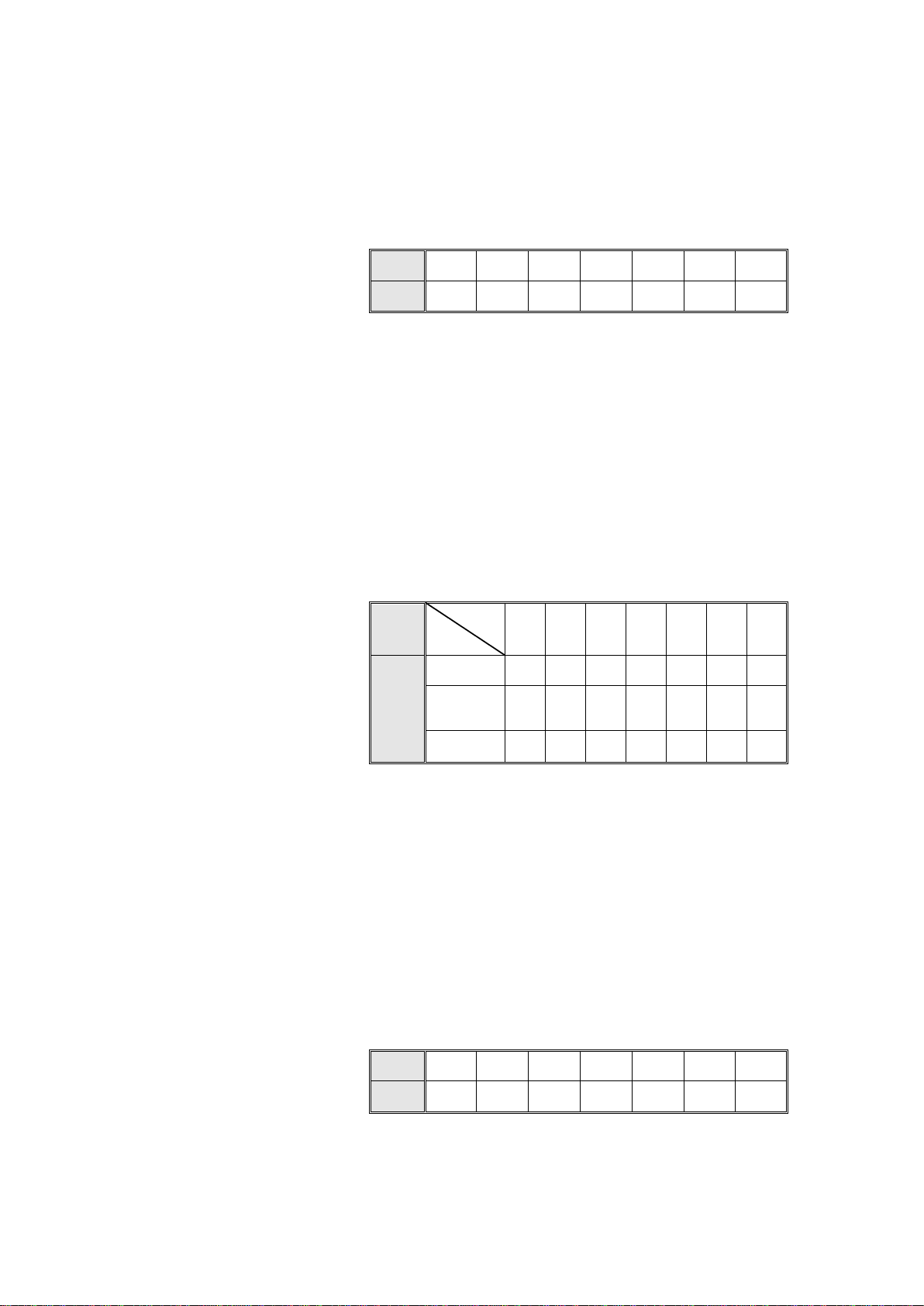
9.2.2 STER Time – Required sterilization time for the process
Entry code – 1
Resolution – 1 minute
Minimum value – 3 minutes
Cycle
Value
1 2 3 4 5 6 7
134 121 121 121 105 121 0
Maximum value – 99 minutes
Set
value
Cycle
Value
1 2 3 4 5 6 7
3 15 20 20 18 30 0
Page 22 of 132 Pages
Page 25

9.2.3 Dry Time – Required drying time for the process
Entry Code – 1
Resolution – 1 minute
Minimum Value – 0 minutes
Maximum Value – 99 minutes
Set
value
9.2.4 Water Time – Time for entering water to the autoclave
This value defines the entry time of the water to the autoclave to
locate the electrode touching the water.
This time will change from process to process and even for different
autoclaves.
When the autoclave is vertical and the defined time is Ø seconds, the
water valve will not open at all.
Entry Code – 11
Resolution – 1 second
Minimum Value – 1 second
Maximum Value – 200 seconds
Set
value
Cycle
Value
Cycle
Value
1 2 3 4 5 6 7
0 0 0 0 0 0 0
1 2 3 4 5 6 7
20 20 20 20 20 20 20
9.2.5 Heat T.O. - The maximum time allowed for the heating stage
(testing)
After this time, if the system does not enter the sterilization stage, it
will receive a ‘Low Heat’ message and the process will abort.
Entry Code – 11
Resolution – 1min
Minimum Value – 20min
Maximum Value – 300 min
Set
value
Cycle
Value
1 2 3 4 5 6 7
60 60 60 90 90 90 0
Page 23 of 132 Pages
Page 26

9.2.6 End Temp - The ending temperature of the process
If at the end of the process the temperature is higher than this
temperature, the process will not end and the door will remain closed.
Entry Code – 11
Resolution – 1ºC
Minimum Value – 40ºC
Maximum value – 137ºC
Set
value
9.2.7 PulsNum. – No. of pulses in the prevacuum stage
Entry Code – 11
Resolution – 1
Minimum Value – 1
Maximum Value – 5
Set
value
9.2.8 VacDip1 – Vacuum value in the first pulse
Defines the vacuum value in pulse no.1 of the prevacuum stage.
Entry Code – 11
Resolution – 1kpa
Minimum Value – 1kpa
Cycle
Value
Cycle
Value
1 2 3 4 5 6 7
120 120 100 85 85 85 134
1 2 3 4 5 6 7
2 1 2 1 1 1 1
Maximum Value – 90kpa
Set
value
9.2.9 VacDip2 – Vacuum value in the remaining pulses
This value defines the vacuum in the remaining pulses in the
prevacuum stage (not just pulse no. 2)
Entry Code – 11
Resolution – 1kpa
Minimum Value – 1kpa
Maximum Value – 90kpa
Set
value
Cycle
Value
Cycle
Value
1 2 3 4 5 6 7
12 20 20 20 20 20 20
1 2 3 4 5 6 7
20 20 20 20 20 20 20
Page 24 of 132 Pages
Page 27

9.2.10 Vac Time 1 – Vacuum Time in the First Pulse
This value defines the time the system will continue to maintain
vacuum after reaching Vac Dip1 for the first pulse.
Entry Code – 11
Resolution – 30sec
Minimum Value – 1sec
Maximum Value – 1800sec
Set
value
9.2.11 VacTime2 – Waiting time for the remaining pulses
In the remaining pulses starting from pulse no. 2 in the prevacuum
stage, after arriving at the VacDip2, stage there is a time delay,
defined as VacTime2 (in seconds), that the vacuum system continues
working.
Entry Code – 11
Resolution – 30 seconds
Minimum Value – 1 second
Maximum Value – 1800 seconds (30 minutes)
Default Value – 240 seconds
Set
value
9.2.12 Ex Mode – The method for exhausting the steam at the end of the
process
Entry Code – 11
Cycle
Value
Cycle
Value
1 2 3 4 5 6 7
30 30 30 30 30 30 30
1 2 3 4 5 6 7
30 30 30 30 30 30 30
Resolution – 1
Ex Mode
Fast Ex 1
N.A. 2
Slow Ex (Waste) 3
Slow Ex (Liquids) 4
Cooling with compressed air 5
Cooling with water circulation 6
Set
value
Cycle
Value
1 2 3 4 5 6 7
1 1 3 4 4 6 1
Page 25 of 132 Pages
Page 28

9.2.13 LimitP add – The allowable addition to the maximum pressure in
every process
If the maximum pressure is 225kpa, the system will not heat beyond
this pressure. If LimitP add will be Ø , the maximum pressure will
remain 225kpa. If LimitP add equals 10, the maximum pressure will
be 235kpa.
Entry Code – 11
Resolutio – 1kpa
Minimum Value – Ø kpa
Maximum Value – 30kpa
Set
value
9.2.14 Calib Code – Calibration Code
This allows entry to the calibration mode.
It must be set on 107 in order to allow the code to be entered.
Entry Code – 11
Resolution – 1
Minimum Value – Ø
Maximum Value – 255
Set
value
9.2.15 Ex Time
This defines the time the exhaust valve should remain open after
reaching a pressure of 127kpa for removing the water in the chamber.
In some autoclaves 15 seconds is enough, and in the large autoclaves
it is possible that there will be a need to extend this to 40 seconds.
Cycle
Value
Cycle
Value
1 2 3 4 5 6 7
0 0 0 0 5 0 0
1 2 3 4 5 6 7
100 100 100 100 100 100 100
Entry Code – 11
Resolution – 10 sec
Minimum Value – Ø sec
Maximum Value – 240 sec
Set
value
Cycle
Model
2540 45 45 30 30 30 30 30
3150/70 45 45 30 30 30 30 30
Value
3850/70 45 45 30 30 30 30 30
5050/75 60 60 60 60 30 45 30
Page 26 of 132 Pages
1 2 3 4 5 6 7
Page 29
9.2.16 VacPump – Does the autoclave have a vacuum pump?
VacPump
There is no vacuum pump in the autoclave Ø
There is a vacuum pump in the autoclave 1
Entry Code – 33
Resolution – 1
Set
value
9.2.17 AutoSize – Size of the Autoclave:
This parameter defines the size of the autoclave by the following
details:
2540 Ø
3850,3870 1
3150,3170 1
5050,5070 2
Entry Code – 33
Resolution – 1
Set
value
Cycle
Value
Value
1 2 3 4 5 6 7
0 0 0 0 0 0 0
AutoSize
Cycle
Model
2540 0 0 0 0 0 0 1
3150/70
3850/70
1 2 3 4 5 6 7
1 1 1 1 1 1 1
9.2.18 Req Prs+
This defines the required addition to the sterilization pressure in kpa.
For example, for a sterilization temperature of 121ºC the required
pressure is 204kpa. Since the system controls the sterilization process
according to pressure and temperature, if Req Prs+ equals Ø , the
system will maintain the pressure at 204kpa. If the value is at 5kpa,
the system will be maintained at 209kpa, and so on.
Entry Code – 33
Resolution – 1
Minimum Value – 0kpa
Maximum Value – 15kpa
Set
value
Cycle
Value
505075 2 2 2 2 2 2 2
1 2 3 4 5 6 7
5 3 1 1 1 1 1
Page 27 of 132 Pages
Page 30

9.2.19 NO Drain
This is intended for vertical autoclaves only, and defines if the water
will drain at the end of the process or not.
Water drains at end of process – Ø
Water remains in the chamber – 1
Entry Code – 11
Resolution – 1
Minimum Value – 0
Maximum Value – 1
Set
value
9.2.20 Water Max
The maximum allowable time in seconds for water entery (generally it
will be 180 seconds).
Entry Code – 11
Resolution – 1 sec.
Minimum Value – 1 sec.
Maximum Value – 1200 sec.
Set
value
9.2.21 Ex Rate
It sets the rate of the exhaust in the slow exhaust. It is possible in
autoclaves that have a top exhaust valve. A combination of natural
exhaust (through the condense valve) and the operation of the top
exhaust valve in Shoot Mode when:
Cycle
Value
Cycle
Value
1 2 3 4 5 6 7
0 0 0 0 0 0 0
1 2 3 4 5 6 7
400 400 400 400 400 400 180
Entry Code – 11
Resolution – 1 (step)
Minimum Value – 0
Maximum Value – 5
Ex Rate Top Exhaust
0 = Closed
1 = 5% of the time Open
2 = 20% of the time Open
3 = 35% of the time Open
4 = 50% of the time Open
5 = 70% of the time Open
Set
value
Cycle
Value
1 2 3 4 5 6 7
0 0 0 0 0 0 0
Page 28 of 132 Pages
Page 31

9.2.22 Factor
This sets the air pressure in the chamber during sterilization and
cooling in the Hot Water method.
For example: if the temperature in the chamber is 121ºC, and the
suitable steam pressure is 205kPa, if the selected factor is 1.5, the
pressure that will be kept in the chamber will be 205 x 1.5 = 307.5kPa.
Entry Code – 33
Resolution – 0.1
Minimum Value – 1
Maximum Value – 2
Set
value
9.2.23 Hot Wtr
Entry Code – 33
Resolution – 1
Minimum Value – 0
Maximum Value – 1
Selections:
Ø – Regular sterilization with water heating the steam
1 – The sterilization will be with a circulation of hot
Set
value
9.2.24 Temp2+
For Hot Water systems, there is an extra sensor placed outside of the
liquid media to measure the temperature of the hot water. If this
temperature rises above the value of the Ster. Temp and
Temp2+combined, then the heating elements will shut down.
Cycle
Value
water and a backup of compressed air.
Cycle
Value
1 2 3 4 5 6 7
1.5 1.5 1.5 1.5 1.5 1.5 1.5
1 2 3 4 5 6 7
0 0 0 0 0 0 0
For example, if Ster Temp is 121C, and Temp2 is 3C, if the hot
water temperature outside the liquid rises above 124C (i.e. 124.1C
or above), the heaters will not activate.
Entry Code – 33
Resolution – 1C
Minimum Value – 1C
Maximum Value – 5C
Set
value
Cycle
Value
1 2 3 4 5 6 7
3 3 3 3 3 3 3
Page 29 of 132 Pages
Page 32

9.2.25 DryPulss
If the system contains a vacuum pump (i.e. the Vac Pump parameter =
1), and a dry stage is required, the air valve will open or close
according to the value of DryPulss.
If DryPulss = 0, the air valve remains closed.
If DryPulss = 1, after 4 minutes of evacuating the chamber during the
dry Stage, the air valve will open in shoot mode of 10 seconds on and
50 seconds off.
Entry Code – 33
Resolution – 1
Minimum Value – 0
Maximum Value – 1
Set
value
9.3 Resetting the Autoclave
Whenever certain data, stored in the back-up memory, must be erased the
system must be reset, in order to restore the system to normal operation or for
situations that follow:
— When the machine is operated for the first time or after a long interruption,
and disorders appear in the operations sequence.
— When operation was stopped in the middle of the cycle, as a result of a
power failure or manual stop and the cycle has not been completed.
To reset the system; proceed as follows:
— Turn the main power switch OFF.
— Turn the main power switch ON, while pressing the SEL. CYCLE key,
until the program parameters are displayed.
After resetting the autoclave, the autoclave is in stand-by mode
9.4 Test Mode
Turn on the main power switch, while pressing the UP key continuously, to
enter the Test mode.
The output test will start (valves, heater, pump), each output will be activated
for one second and its name will be displayed. To switch from one output to
another, press each time the UP key.
Keep pressing the UP key, the inputs test is performed, pressing each time the
UP key the next input is selected.
The same way the temperature and pressure values are displayed.
Cycle
Value 0 0 0 0 0 0 0
1 2 3 4 5 6 7
Page 30 of 132 Pages
Page 33

10. REPLACING ELEMENTS
10.1 Safety Tests after Repair
ATTENTION!
After every repair or dismantling the enclosure, the autoclave should pass
two safety electrical test by the Service Engineer. The following shall be
performed:
1. Enclosure Leakage Current Test.
Every autoclave should pass this test as follows:
1. Remove the service doors.
2. Disconnect receptacle from JP3.
3. Remove all fuses.
4. Connect the electrical cord to the autoclave.
5. Turn on the circuit breaker.
6. Short-circuit the L and N pins on the cord's plug.
7. Connect the Short-circuit pins to the L pole on the Megger.
8. Connect the earth pins to the earth pole on the Megger.
9. Impose an electrical potential of 500-1000V on the tested autoclave.
The insulation resistance should be at least 2 MΩ.
The test is successful if there was no leakage.
2. Protective Earth Impedance Test
1. Connect the grounding pin of the power cord plug to one pole of an
Ohmmeter.
2. Connect any other metallic part (preferable – the metallic part of the
locking screw) to the second pole of the Ohmmeter.
3. The resistance should not exceed 0.3 Ω.
After performing these tests, the Service Engineer should complete and sign
the Work Order.
Page 31 of 132 Pages
Page 34

10.2 Replacing the Circuit Breaker
Caution!
Before starting, disconnect the instrument from the power source.
1. Open the right door.
2. Disconnect the wires from the circuit breaker.
3. Remove four screws connecting the circuit breaker to the panel (1).
4. Replace the circuit breaker with a new one.
5. Reconnect the electrical wires.
6. Reassemble the cover.
7. Turn on the autoclave and verify it operates correctly.
8. Move the circuit breaker’s lever to the “tripped” position and verify
that the autoclave turns off.
Make sure that the correct circuit breaker is installed according to the
table below!
Model Power
2540
3150/70
3850/70
3850/70
3850/70 with switching box
3850/70, 5050/75
5050/75
5050/75
5050/75 with switching box
Circuit breaker
1Ph, 230V/50/60Hz 1Ph/15A
1 or 2 Ph, 230V/50/60Hz 1Ph/20A
3 Ph, 208V/50/60Hz 3Ph/20A
3 Ph, 230V/50/60Hz 3Ph/20A
1 or 2 Ph, 230V/50/60Hz 3Ph/15A
3 Ph, 400V/50/60Hz 3Ph/15A
3 Ph, 208V/50/60Hz 3Ph/25A
3 Ph, 230V/50/60Hz 3Ph/25A
1 or 2 Ph, 230V/50/60Hz 3Ph/15A
For models
2540, 3150, 3170
For models
3858, 3870, 5050, 5075
Page 32 of 132 Pages
Page 35

10.3 Replacing the Safety Valve
For models 5050, 5075
Warning:
Before starting, disconnect the instrument from the power source and
ensure that there is no pressure in the autoclave chamber.
Note:
These instructions are valid for both, CE-marked (as in the drawing
below) and ASME type safety valves.
1. Open the right door.
2. Disconnect the pipe connection.
3. Unscrew the safety valve (including the base For models 2540, 3150,
3170, 3850, 3870 or elbow for models 5050, 5075) and remove from the
autoclave.
4. Replace it with a new safety valve (use an original only).
5. Test autoclave cycles.
1
1
4332
6 3 5
For models 2540, 3850, 3870
Cat. No.
Description
1
CE-marked
2540, 3150,
3170, 3850, 3870
5050, 5075
SVL029-0028 SVL029-0005
Safety valve
1
2 Safety valve base CMV100-0004
ASME
SVL029-0004 SVL029-0007
3 Washer CMT240-0022 LOK505-0001
4 Nut CMT240-0020
5 Street elbow F*M ½*½ 90
6 Male connector ½*½
Page 33 of 132 Pages
FIT100-0065
FIT100-0296
Page 36

10.4 Replacing the Door Gasket
10.4.1 For models 2540, 3150, 3170, 3850, 3870
1. Pull off the gasket from the door groove.
2. Clean the slot
3. Install the new gasket referring to the drawings above 1, 2 and
3.
Caution!
This gasket is designed with a trapezoidal cross section. The
gasket should be placed with the widest side towards the door.
10.4.2 For models 5050, 5075
1. Disassemble the 12 segments (1) attaching the gasket to the
door.
2. Remove the gasket (5) from the door.
3. Clean the door surface.
4. Lay the new gasket on the door.
5. Assemble the segments loosely. Verify that the rim of the
gasket (4) is in the groove in the segments (3).
6. After all the segments are assembled loosely verify that the
gasket lies evenly.
7 tighten all the screws (2) of the segments.
1
2
5
3
4
Page 34 of 132 Pages
Cat. No.DescriptionNo.
LOK507-0021Segment1
BOL191-0092Screw M5 x 122
GAS080-0005Gasket5
Page 37

10.5 Replacing the electronics board (control panel)
Caution!
Make sure that the power cord is disconnected!
If the electronic box was damaged by any liquid that entered the box, do not
attempt to replace it. In this case only the factory technicians may repair the
autoclave.
Allow the autoclave to cool before removing outer covers.
For description of items numbered in brackets see table in para. 10.6.
1. Open the right service door.
2. Unscrew the screws of the electronic box cover (8) and remove the cover
(12).
3. Remove the screws that connected the plastic panel with the digital
electronic board to the autoclave (2).
On model 2540 remove 2 screws placed on the “head” and the “foot”
of the panel.
On models 3150, 3170, 3850, 3870 remove 3 screws placed on the
“head”, the “foot” and the side of the panel
On models 5050, 5075 remove 6 screw both sides of the keyboard
panel
4. Disconnect the flat cable from JP1-DIG-T2 to JP1 ANL-T2 (4).
5. Disconnect the flat cable of communicator from P1-ANL-T2 (6).
6. Disconnect the grounding cable shoe (green cable) (5).
7. If the autoclave is equipped with a printer, disconnect the printer cable.
8. Remove the main switch.
On autoclave model 2540, 3170, 3850, 3850, 3870 disconnect the
main switch (7).
On models 5050, 5075 remove the main switch (7) from the panel
without disconnecting it.
9. Remove the plastic panel, including the electronics board (control panel),
from the autoclave.
10. If replacement of the control panel is required, unscrew four fastening
screws located on the rear of the panel. Remove the control panel from the
plastic panel and replace it with a new one.
Page 35 of 132 Pages
Page 38

10.6 Replacing the Electronics Box
BOL194
-
BOL194
-
BOL194
-
BOL191
-
BOL194
-
BOL194
-
BOL194
-
BOL194
-
BOL194
-
BOL194
-
BOL194
-
BOL194
-
BOL194
-
BOL194
-
BOL194
-
BOL194
-
NUT192
-
NUT192
-
NUT193
-
NUT193
-
NUT193
-
BOL191
-
CMT254
-
CMT315
-
CMT240
-
CMT507
-
Caution!
Make sure that the power cord is disconnected!
If the electronic box was damaged by any liquid that entered the box, do not
attempt to replace it. In this case only the factory technicians may repair the
autoclave.
Allow the autoclave to cool before removing outer covers.
1. Open the right service door.
2. Unscrew the screws adjacent to the fan grid (3).
3. Disconnect all the electric system connectors from the electronics base
(including the MPX connectors).
4. If the autoclave is equipped with a printer, disconnect the printer cable.
5. Unscrew the screws fastening the circuit breaker panel (9) and release the
panel.
On model 2540 release the panel.
On models 3150, 3170, 3850, 3870 remove 2 nuts, washers and spring
washers (10).
On models 5050, 5075 remove 2 screws, nuts, washers and spring
washers (10).
6. Remove electronics box and replace with new one.
7. Re-assemble the instrument. Verify that the grounding connections are
connected correctly.
8. Test any cycle and verify that the autoclave operates as required.
0340
0341
0340
0340
0185
0276
0317
Cat No.
0340
0341
0340
0340
0185
0276
NUT193-
0317
0140
0341
0340
0340
N
o.
Description
2 Screw
3 Screw
8 Screw
9 Screw
Nut
Washer
Spring Washer
10
¼
2540 3150, 3170 3850, 3870 5050, 5075
0340
0341
0340
0340
NUT193-
Star Disk
Screw
Sheet Nut
11
4.8x1.25
12 Cover
NUT192-
0230
0020
NUT192-
0230
0001
NUT192-
Page 36 of 132 Pages
0230
0031
0291
0140
NUT192-
0230
0008
Page 39

11
7
8
12
52
2
1
2
4
3
6
Electronic box 3850, 3870
Page 37 of 132 Pages
Page 40

3870ELV Rear Side
3
9
10
Electronic Box – Internal Front Side
Page 38 of 132 Pages
Page 41

10.7 Cut-Out Thermostat
Warning:
Before starting, disconnect the instrument from the power source and ensure
that there is no pressure in the autoclave chamber.
This thermostat cuts out the power to the autoclave, in the event that all other
safety systems malfunction. For example: if the autoclave operates without
water in the chamber, the PT100 detect this and the control unit cuts the
electricity to the heaters.
If the temperature still rises, then the cut-out thermostat will cut-out the power
to the autoclave. In order to restart the operation press the RESET Button. If
the autoclave is operated according to instructions, and the thermostat cuts out
again, a service technician should be called.
10.7.1 Replacing the Cut-Out Thermostat
1. Disconnect the cut-out sensor (3) from the heating elements
(2).
1. Unscrew the nut fastening the reset button (1).
2. Unscrew the nut (6) from the bushing (5).
3. Remove the faulty thermostat and replace it with a new one
(use an original only).
4. Reconnect the cut-out sensor to the heating elements, using the
fasteners (4).
4. Reinstall the bushing. Use a sealant to ensure sealing.
4 3
1
2
5
Cut-Out Thermostat
Reset button
6
Page 39 of 132 Pages
Page 42

10.8 Replacing Heating elements
HEA012
-
HEA012
-
HEA012
-
HEA012
-
SPR177
-
SPR177
-
SPR177
-
SPR177
-
GAS083
-
GAS083
-
GAS083
-
GAS083
-
Caution:
Before starting, be sure that the electric cord is disconnected from the power
source and that there is no pressure in the autoclave chamber.
1. Turn the autoclave and lay it on its side.
2. Disconnect the cut-out sensor (2) from the heating elements (1).
3. Disconnect the electrical wires (7) from the heating elements.
4. Unscrew the nut fastening the heating element (5) and remove the gasket
(3).
5. Push the heating element inward and take it out.
6. Replace the heating element.
7. Reconnect the cut-out sensor to the heating elements, using the fasteners
(3).
8. Reconnect the electrical wires to the heating elements. Verify that the
isolating tubes (6) are assembled too.
9. After replacing the heating element run a cycle and verify that it operates
as required and that there is no leakage.
10. Close the autoclave’s service door.
11. Test the autoclave by performing a full cycle.
7
.
6 5 34 2
Description 2540
1 Heating element
2 Cut-out sensor
3 Cut-out sensor fastener
4 Gasket ring
3150/31703850/38705050/507
0005
N/A N/A N/A N/A
0014
N/A N/A N/A N/A
0006
0014
0007
0014
0008
0014
1
5
Heating element fastening
5
nut
6 Isolating tubes
Heating elements
7
electrical wire
N/A N/A N/A N/A
0003
N/A N/A N/A N/A
0003
0003
Page 40 of 132 Pages
0003
Page 43

10.9 Safety Door Locking System for models 2540, 3150, 3170, 3850, 3870
Door locking is achieved by means of two safety devices, a pull type solenoid
which must be powered to enable the opening of the door and a pressure activated door locking.
10.9.1 Solenoid Locking Device
The solenoid locks the door in the following situations:
When the control unit is not powered.
a. If power failed or has been turned off while the autoclave is in
operation, even if power has been restored.
b. If operation was stopped before completion of the cycle as a
result of a failure or a manual stop.
c. When the temperature inside the autoclave chamber is higher
than the end of the cycle temperature, preset by the operator;
the opening of the door is possible only when the temperature
has dropped below the pre-set value.
The release of the door locking is done automatically at the
completion of a normal cycle. In case of failure or manual stop,
release the door locking by pressing the STOP key.
For model 2540
For models
3150, 3170,
Page 41 of 132 Pages
Page 44

10.9.2 Replacing the Solenoid Locking Device
Caution!
Before starting, disconnect the instrument from the power source
and ensure that there is no pressure in the autoclave.
For description of the locking device see next page.
1. Remove the door cover.
2. Disconnect the wires from the connector.
3. Unscrew the tightening nut (cat. No. CMT201-0004).
4. Remove the pin, the spring and the solenoid.
5. Replace the damaged items and reinstall according to drawing
below.
6. Operate the autoclave and verify that the pin is retracted when
the cycle reaches “stand-by” stage.
10.9.3 Emergency Door Opening
In order to facilitate the initial installation, the door locking position
is taped in this retracted position at the factory. On completion of all
installation activities this tape must be removed. If for any reason the
door locking mechanism is permanently locked, it is possible to open
the door and provide access for eventual repairs to the locking
mechanism. The swing bolt has a drilled opening located in the lock
catch. By pushing the piston back with a 2mm. pin, the swing bolt
may be turned another 3/4 turn until the position catches again.
Repeat these operations until the bolt can be swung away and the
door opened.
Page 42 of 132 Pages
Page 45

10.10 Safety Door Locking System for models 5050, 5075
To release the door locking to cancel the door locking at the end of operation;
press the UP key
An additional door safety device is fitted to the models, 5050, 5075, which
work with a central closing mechanism. This device is a piston-cylinder
assembly valve, activated by one of the radial locking arms and connecting the
chamber to the open atmosphere, through a small nozzle.
When the first step of opening the door is performed and arms are unlocked
turning the handle counter-clockwise, the arms change direction, the piston is
released and valve opens, chamber is aerated and residual pressure discharged
from the chamber.
Following this, opening the door by pulling it, can be done safely, with no risk
for the operator, of steam or hot water burst.
Safety locking device
Safety opening device
Locking solenoid
Two microswitches ensure that operation cannot be started if autoclave door is
unlocked; one is activated by the door, when it is lowered down to the frame,
the second by one of the arms in position locked. When the two micro-switches
are pressed, the light “DOOR” on the keyboard panel is OFF and operation can
be initiated.
Page 43 of 132 Pages
Page 46

10.11 Disassembling and Assembling the Door Cover, Models 2540, 3150, 3170,
3850, 3870
Caution:
Before starting, be sure that the electric cord is disconnected from the power
source and that there is no pressure in the autoclave chamber.
1. Unscrew the four screws attaching the door cover and remove the door
cover. Since the screw pressing the door microswitch includes two washers
and a spring, be aware not to lose them.
2. Reassemble the new cover.
3. When assembling covers on models 3850/3870 place a washer (7) between
the door cover (6) and the door flange (5) – on all 4 flanges (in the drawing
below the washer is hidden).
4. To assemble the screw that is pressing the door switch, insert screw (1)
until dimension A is approximately 15 mm.
4.1 Please note that on models 3150/70 two washers (3) are placed
between the spring (4) and the door.
5. Perform final adjustment of the screw as follows:
5.1 While the autoclave is disconnected from electricity turn on the
circuit breaker.
5.2 Connect the electrical plug to a multi-meter.
5.3 Press the microswitch and verify that the microswitch functions as
required.
5.4 Close the door and verify that the microswitch operates.
5.5 If the microswitch does not operate unscrew the screw one turn
counter- clockwise and check per para. 4.4. Repeat until microswitch
operates.
5.6 Connect the autoclave to electricity.
5.7 Close the door until the microswitch indicates that the door is closed.
Operate the autoclave and verify that there is no steam or pressure
leak.
5.8 If there is steam leak, stop the autoclave’s operation, reduce steam
pressure, open the door and turn the screw one turn clockwise and
check per para. 5.7. Repeat until leakage ceases.
6. After assembling the door cover stick the model label (see spare parts list)
in the sunken surface.
Page 44 of 132 Pages
Page 47

2540
POL065
-
0053
washer
A
7
6
2
15343
No. Description Model
2540 BOL191-0032 3 washer All models ELE036-0009
1 screw
2 screw
3150, 3170
3850, 3870
2540 BOL191-0033 3150, 3170 COV314-0001
3150, 3170 BOL191-0115 3850, 3870 POL065-0044
3850, 3870 BOL191-0082 7
Cat. No.
BOL191-0091
No. Description Model
4 spring All models SPR177-0012
6 door cover
(hidden)
3850, 3870 NUT193-0270
Cat. No.
Page 45 of 132 Pages
Page 48

10.12 Disassembling and Assembling the Door Cover, Models 5050, 5075
10.12.1 Disassembling the Door Cover
Warning:
Before starting, disconnect the instrument from the power source
and ensure that there is no pressure in the autoclave chamber.
1. Release the two (2) fastening screws (1).
2. Remove the locking handle (10) and the Teflon ring (9).
3. Remove the screws covers (2).
4. Unscrew the cover fastening screws (3, 5) and remove the
screws and the washer (4).
5. Remove the door cover. Be careful not to loose the springs (6)
and the washers (4a) located beneath the door cover. Washer
(7) is a disposable nut and must be replaced buy a new nut
when the door cover is re-assembled.
10.12.2 Assembling the Door Cover
1. Place the Teflon disk (9) on the door handle axis.
2. Place and hold the spring (6) and the washer (4a) on the spacer
(8). Place the door as near as possible to its place and insert the
screw (3) with the washer (4) on the screw, through the hole in
the door, into the spacer (8). Do not tighten the screw.
3. Repeat this operation with the second screw.
4. Open the door.
5. Insert the screw (5) with the washer (4b) on the screw, through
the holes in the door and in the hinge. Screw nut (7) slightly
(do not tighten it).
6. Adjust the door and tighten all four screws.
7. Place the screw caps (2)
8. Place the second Teflon disk (9) on the door handle axis.
9. Install the door handle on the axis and fasten the fastening
screws (1).
Page 46 of 132 Pages
Page 49

Page 47 of 132 Pages
Page 50

No. Description Cat. No.
1 Screw BOL191-0002
2 Screw cover ARM067-0004
3 Screw M5 x 35 mm BOL191-0143
4 Washer 3/16 NUT193-0275
5 Screw M5 x 1” BOL191-0155
6 Spring SPR177-0010
7 Self locking nut M5 NUT192-0221
9 Teflon washer LOK507-0035
11 Cover, Door POL065-0005
Page 48 of 132 Pages
Page 51

10.13 Replacing the locking microswitch (Models 5050, 5075)
Caution!
Before starting, disconnect the instrument from the power source and ensure
that there is no pressure in the autoclave.
1. Remove the door cover (see 10.12 “Disassembling and Assembling the
Door Cover”).
2. Unscrew the 2 screws (6) of the microswitch cover and remove the cover
(7).
3. Disconnect the electrical wires in the microswitch (8).
4. Unscrew the two nuts attaching the microswitch to the door (3) and
remove it.
5. Open the cover of the new microswitch (7).
6. Connect the electrical wires to the new microswitch and close the cover.
7. Assemble the new microswitch to the door.
8. Close, but do not tighten, the fastening nuts (3).
9. Close and lock the door. Adjust the location of the microswitch. Verify
that the door lock LED indicates that the door is closed.
10. Tighten the fastening nuts (3).
11. Reassemble the door cover.
1 2 3
No. Description Cat. No.
2 Washer 3/16 NUT193-0275
3 Nut M5 NUT192-0192
5 Microswitch ELE036-0019
4 Spring washer M5 NUT193-0315
4
5
6
7
8
Page 49 of 132 Pages
Page 52

10.14 Replacing the safety-opening valve (Models 5050, 5075)
3
4
5
621
9
8
7
Caution!
Before starting, disconnect the instrument from the power source and ensure
that there is no pressure in the autoclave.
1. Remove the door cover (see 10.12 “Disassembling and Assembling the
Door Cover”).
2. Unscrew the locking arm guide (1).
3. Unscrew the screw assembled on the valve’s piston rod (9).
4. Remove the side bracket (7).
4. Remove the screw fastening the valve to the side bracket (3, 4, 10).
5. Remove the faulty safety valve (2) by turning it counter-clockwise and
unscrewing it from the autoclave’s cover.
6. Install the new valve
7. Install the screw (9) (with the nut (8) on it) on the piston rod.
8. Re-install the locking arm guide (1). Verify that the right guide is installed,
since this guide and the guide of the arm attached to the safety locking
microswitch defers from the other.
9. Re-install the side bracket (7).
10. Set the locking devise to “lock” position.
11. Adjust the screw on the piston rod (9). Turn the screw while the screw
head touches the bracket welded on the locking arm. When the piston rod
is pressed completely inward secure the setting with the nut (8).
12. Reassemble the door cover.
.
Description Cat. No.
1 Arm guide
-0031 6
No
.
Description Cat. No.
Spring washer
M5
2 Valve PNE195-0054 7 Side bracket
Spring washer
3
¼”
4 Nut ¼”
-0317 8 Nut M6
-0185 9 Screw M6
-0315
-0001
-0193
-0150
5 Nut M5
-0192 10 Screw ¼ x 1½
-0174
Page 50 of 132 Pages
Page 53

10.15 Replacing the “DOOR CLOSED” microswitch (Models 5050, 5075)
325
8
1
476
A
Caution!
Before starting, disconnect the instrument from the power source and ensure
that there is no pressure in the autoclave.
1. Open the left service door.
2 unscrew the two nuts fastening the bracket to the autoclave (1).
3. Remove the bracket with the microswitch and unscrew the two screws
connecting the microswitch to the bracket (2).
4. Unscrew the 4 screws of the microswitch cover (3) and remove the cover.
5. Disconnect the electrical wires in the microswitch (4).
6. Open the cover of the new microswitch.
7. Connect the electrical wires to the new microswitch and close the cover.
8. Assemble the microswitch to the bracket. Verify that the distance between
the microswitch and the edge of the bracket (A
) is 5-6 mm.
9. Reassemble the bracket with the microswitch on the autoclave.
10. Turn on the autoclave and close the door.
11. Verify that the display indicates that the door is closed.
12. If the display does not indicate that he door is closed disassemble the
bracket and increase the gap (A) by 1 mm.
13. Repeat steps 10, 11.
.
Description Cat. No.
1 Nut M5
.
Description Cat. No.
-0192 4 Bolt ¼ x ¾
-0142
2 Washer 3/16
3 Spring washer M5
-0275 5 Nut ¼ with flange
-0315 8 Microswitch ELE036-0004
Page 51 of 132 Pages
-0155
Page 54

10.16 Replacing the solenoid lock (Models 5050, 5075)
3
Caution
Before starting, disconnect the instrument from the power source and ensure
that there is no pressure in the autoclave.
1. Remove the door cover (see 10.12 “Disassembling and Assembling the
Door Cover”).
2. Disconnect the electrical wire from the porcelain connectors (1).
3. Unscrew the locking solenoid (2) from the lock housing.
4. Remove the locking pin (3) with the Teflon ring (4).
5. Remove the spring (5) from the solenoid.
6. Insert the spring in the new solenoid.
7. Check the Teflon ring and verify that it is not damaged. If it is damaged
replaced it with a new Teflon ring. Verify that the ring is placed on
shoulder side facing the solenoid.
8. Insert the solenoid into the lock housing and screw it tightly.
9. Connect the electrical wires.
10. Check the solenoid by connecting one wire to a 12V source and the other
wire to ground. Verify that the pin is retracted.
54
No. Description Cat. No.
1 porcelain connectors ELE039-0049
2 locking solenoid SOL027-0001
3 locking pin LOC507-0001
4 Washer, locking Solenoid Pin LOK387-0017
2
5 Spring, Door Lock, Solenoid SPR177-0017
Page 52 of 132 Pages
Page 55

10.17 Cleaning and Replacing the Water Level Electrodes
The water level electrodes are located at the bottom part of the chamber wall.
10.17.1 Replacing
Caution
Before starting, disconnect the instrument from the power source
and ensure that there isno pressure in the autoclave.
Allow the autoclave to cool before removing outer covers.
1. Open the right service door.
2. Disconnect the wire from the electrode connection.
3. Open the nut that tightens the electrode.
4. Insert a new electrode and tighten the fixing nut to avoid
leakage.
5. Reconnect the wire to the electrode.
6. Test the unit.
10.17.1.1 Cut-off electrode adjustment
1. While the autoclave does not operate let water enter
then chamber until the heating elements are covered.
2. Verify that when the heating elements are covered
there is a gap between the water surface and the cutoff electrode.
3. If there is no gap – readjust the position of the
electrode.
10.17.2 Cleaning
1. Remove the basket from the autoclave.
2. Clean the electrode tip.
3. Test the unit.
Water Level Electrode Assembly Cat No. CMT196-0004
NOTE:
For models 5050/5075 use electrode P/N CMT196-0005. In this assembly
CMV196-0001 replaces CMV196-0002.
Page 53 of 132 Pages
Page 56

10.18 Replacing the Printer
10.18.1 DPU20 Printer
Caution!
Before starting, disconnect the instrument from the power source.
1. Remove the right service door of the autoclave.
2. Disconnect the connector of the flat cable (1) connecting the
electronic box to the printer (2).
3. Unscrew the two screws (3) attaching the fastening bracket (4)
to the printer.
4. Remove the printer and insert the new one.
5. Assemble the fastening bracket to the printer with the two
screws (2) and verify that it "sits" firmly in its seat.
6. Connect the flat cable (1) to the printer.
7. Verify connection of power by performing a self-test.
8. Run a cycle and verify that the printer operates correctly.
No. Cat. No. Description
1 WIR040-0070 Cable, Flat, Printer, DPU20, 25CM, 34P
2 THE002-0005 Printer, DPU-20, Seiko
3 BOL190-0144 Screw, printer tightening
Supplied with the
4
printer
Fastening bracket
1
2
3
4
Page 54 of 132 Pages
Page 57

10.18.2 DPU30 Printer
5, 6, 7
1, 2, 3, 4,
8,
9up10
Caution!
Before starting, disconnect the instrument from the power source.
1. Remove the right service door of the autoclave.
2. Disconnect the connector of the cable (1) connecting the
electronic box to the printer (2).
3. Unscrew the two screws (3) attaching the fastening bracket (4)
to the printer.
4. Remove the printer.
5. Set the dip switches on the new printer, located on the back side
of the printer, as follows:
up
down
down
6. Insert the new printer into its frame.
7. Assemble the fastening bracket to the printer with the two
screws (2) and verify that it is placed firmly.
8. Connect the (1) cable to the printer.
9. Verify connection of power by performing a self-test.
10. Run a cycle and verify that the printer operates correctly.
1
2
3
4
No. Cat. No. Description
1 CTP201-0127 Cable, Printer, DPU-30, 30cm, 34p
2 THE002-0022 Printer, DPU-30, Seiko
3 BOL190-0144 Screw, printer tightening
4 Supplied with the printer Fastening bracket
Page 55 of 132 Pages
Page 58

10.19 Replacing the Door Switch (models 2540, 3150, 3170, 3850, 3870)
231
Caution!
Before starting, disconnect the instrument from the power source and ensure
that there is no pressure in the autoclave.
Allow the autoclave to cool before removing outer covers.
1. Open the left service door
2. Disconnect the wires (1), (2) from the door switch (3).
3. Remove the microswitch and replace it with a new one.
4. Reconnect the wires the microswitch. Verify that the wire is placed on the
isolating cover (4) and does not touch the chamber.
5. Reassemble the door cover.
6. Test the connection with an ohmmeter. In “open” position the ohmmeter
shows disconnection and in “close” position the ohmmeter shows
connection.
Page 56 of 132 Pages
Page 59

10.20 Replacing the Locking Device (models 2540, 3150, 3170, 3850, 3870)
Caution:
Before starting, verify that there is no pressure in the autoclave chamber.
1. Remove the security ring (9) using a special tool.
2. Remove pin (6).
3. Remove locking device. Take care not to lose the Teflon disk (10).
4. Reassemble the new locking device.
5. Insert the pin (6).
6. Reassemble the security ring (9).
CLOSING DEVICE
Cat. No.
No. Description
2540
6 Door locking device pin LOK240-0031 LOK387-0016
9 Closing bridge “c” clip NUT193-0302 NUT193-0303
10 Okolon disc LOK240-0017 LOK387-007
Page 57 of 132 Pages
3150, 3170,
3850, 3870
Page 60

10.21 Replacing the Plunger or Coil of the BACCARA Solenoid Valve
15432
The solenoid valves may be out of order due to faulty plunger or coil. To repair
the solenoid valve – replace the faulty plunger or solenoid
Caution!
Before starting, disconnect the instrument from the power source and
ensure that there is no pressure in the chamber, coil or generator.
Allow the autoclave to cool before removing outer covers.
1. Open the relevant service door to reveal the faulty BACCARA solenoid
valve.
2. Unscrew and remove nut (1).
3. Remove the coil (2).
4. Unscrew the plunger + spring (4) with the plunger housing (3) and replace
it with a new one. The plunger the spring and the housing are replaced as a
kit.
5. Reassemble the coil (2) and the nut (1).
6. Re-install the autoclave cover.
Page 58 of 132 Pages
Page 61

11. IN-OUT TEST
Before performing any trouble shooting on the autoclave, perform an “in-out test”. In
this test the technician tests all the components of the system as follows:
1. Turn on the autoclave and immediately press the Up button until “IN-OUT TEST”
is displayed.
3. Release the button.
4. To proceed, press the UP button. Each time the UP button is pressed the test
advances one step, and the tested component is displayed on the display.
5. When a solenoid is tested, verify that it is activated by touching it with a
screwdriver. If the solenoid is magnetized – it is activated.
6. The autoclave exits the “IN-OUT TEST” when it reaches the last test.
DISPLAYED
NOTICE
Exh On Exhaust valve Exhaust valve is open
Heat on Heating Elements
Water On Water inlet valve Water inlet valve is open
Exh2 On N/A N/A
Air Valve Air inlet valve
Air Release On Air release valve Air release valve is open.
Door Lock On Door lock solenoid
Cool&Circ On Water circulation valve
Comprs Air On Compressed air inlet
Thermostat “0”
Thermostat “1”
ITEM ACTIVATED REMARKS
Heating elements are activated.
Do not perform this test
without water covering the
heating elements
Air inlet valve is open. Applicable
only for ELVC models
Door lock solenoid is open. Verify
that the solenoid has retracted.
Water circulation valve is open.
Applicable only for ELVC.
Compressed air inlet open.
Applicable only for ELVC.
Thermost is in “connected”
Safety thermostat
position
Thermost is in “disconnected”
position
Door Sw “0”
Door switch
Door Sw “1” Door switch open
Electrd-high
255
Electrd-high 13
Electrd-Low
255
Electrd- Low 40
High Water level electrode
High Water level electrode
Page 59 of 132 Pages
Door switch closed
High water level electrode does
not sense water
High water level electrode does
sense water
Low water level electrode does not
sense water
Low water level electrode does
sense water
Page 62

12. TROUBLESHOOTING
12.1 Displayed Messages and Reference to Trouble Shooting
Message Refer to trouble shooting section
Para.
13.2
Low Temp. 1 11, 13
Low Heat 1 4 1 8, 11
High Temp. 1 1 1
Low Pres. 1
High Pres. 1 7, 11,
Add Water 7 10, 28
Door Unlock 2 19
Low Water 1, 2, 3 3 2
Para.
13.3.1
Para.
13.3.2
Para.
13.3.3
Para.
13.3.4
Para.
13.3.5
4, 11,
13, 16
4, 11,
13,
1, 14,
21
13.4
2, 5
2, 4, 5
2, 5
Page 60 of 132 Pages
Page 63

Corrections
connections.
1.1 Replace damaged cord or repair faulty
Possible cause check-up and tests
1.1 Check the power cord and the connections
1.2 Reset cut-off.
at the autoclave input.
1.2 Check the cut-off thermostat.
find out what caused the thermostat to
switch-off.
If operation continues after resetting the cut-off.
“ON” position after fixing the cause for
the short circuit.
1.3 Return the circuit breaker lever to the
there is a short-circuit.
1.3 Check the circuit breaker. If it tripped,
1.4 Check the fuse of the power supply. If the
cause for the short circuit.
1.4 Replace the blown fuse after fixing the
fuse is blown, check if one of the valve
coils or one of the electronic boards
causes a short circuit.
1.5 Check the AC voltages.
system - See Electrical Wiring Diagram.
— The input supplies voltage at the control
— Switch off the power of the unit.
measuring range.
— Set the multitester on the AC voltage
AC-INPUT connector and the positive
probe to pin 1 or 2 on AC-T1 board.
— Connect the negative probe at pin 3 to
instrument must be the same as the power
network voltage. if not:
— Turn on the power. The indication of the
Symptom
system is turned on
12.2 Pre-process malfunction
1. No response when the
Page 61 of 132 Pages
Page 64

Corrections
— Fix connections.
Fasten contacts.
Possible cause check-up and tests
Main power switch\Rocker switch
Restore power source.
— It is possible that the dual power
supplies outputs 12V, but the 5V
circuit is faulty. To identify the faulty
item proceed as follows:
contacts may be loose.
Electrical power source may be faulty.
two electronic boards ANL-T2 and
DIG-T2.
— Check the connection between the
— Check the cable, which transfers the
— Replace faulty cables.
voltage from the AC-T1/JP2
connector to the power supply.
box, at the AC-INPUT connector, on
the AC-T1 board/JP3.
— Check the input voltage of the electric
AC-OUTPUT connector on the AC-
— Check if there is no short-circuit at the
T1 board (JP2).
— Replace faulty connector.
input connector (JP3) or at the output
connector (JP5) on the ANL-T2 board.
— Check if there is no short-circuit at the
Symptom
1. (cont.)
Page 62 of 132 Pages
Page 65

Corrections
— Replace faulty connector.
test board into connector JP5 mounted
Possible cause check-up and tests
system.
Check main power switch.
1.6 Check the DC voltages supply to the
— Plug connector 26 pin FLAT of the
1.6.1 Check the grounding
Replace faulty power switch
on board ANL-T2.
multitester to TP1 on the test board.
— Check with the positive probe of
the multitester the voltage at different
grounding points of the autoclave, on
the ANL-T2 and DIG-T2 boards, on
the enclosure of the electric box and
the main grounding screw of the
machine.
The voltage differences must be less
than 5mV.
Higher voltage may indicate that
ANL-T2 board fastening screws are
loose or that the power supply cable is
loose.
— Connect the negative probe of the
Symptom
1. (cont.)
Page 63 of 132 Pages
Page 66

Corrections
— Tighten loose screws.
Reconnect grounding cable.
Repair or replace the faulty item.
Replace faulty power supply.
Possible cause check-up and tests
Symptom
multitester to TP1 (GND).
— Connect the negative probe of the
multitester to TP3. The indication of
the instrument must be 10.8-12.5V.
— Connect the positive probe of the
disconnect the output connector of the
power supply. If the right value is
achieved ther is a short circuit.
If indication is not as specified,
If instrument indication is below or
above specified range the power
supply is faulty.
Identify and locate the short circuit.
1.6.2 Check the 12VDC voltage.
1. (cont.)
Page 64 of 132 Pages
Page 67

Corrections
internal potentiometer. This operation
must be done with great care to avoid
electrical shock.
1.6.4 calibrate voltage to 2.2V by adjusting the
power supply through the connector
JP2 on the AC - T1 board.
Possible cause check-up and tests
— Check the voltage transfer to the
multitester to TP1 (GND).
— Connect the negative probe of the
multitester to TP2. The indication of
the instrument must be 4.9÷5.3V.
— Connect the positive probe of the
— Check if the fuse of the power supply
— Replace faulty coil and reset fuse.
is blown. It is possible that one of the
valve coils or the electronic board
cause a short circuit.
switch on the unit. If in no-load
condition the power supply delivers
12V and 5V voltages, it can probably
be that there is a problem on one of
the boards, one of the inputs or
outputs.
— Disconnect the power from the AC-
T1 board/connector JP2, and
back to the board and disconnect the
connectors JP6 (inputs), JP5
(outputs), pressure sensor.
— Connect the AV-T1/JP2 connector
Symptom
1.6.3 If neither 12V nor 5V voltages are output:
1. (cont.)
1.6.4 Check the 5VDC voltage.
Page 65 of 132 Pages
Page 68

Corrections
— Replace faulty unit.
board.
Possible cause check-up and tests
— Reapply the power from the ANL-T2
the problem is one of the external
elements connected to the system
(valves, sensors, etc.).
— If the voltages 12V and 5V reappear,
— Replace faulty board.
2.1 Replace the DIG-T2 board
one of the boards is damaged.
Disconnect board DIG-T2 and check
board ANL-T2.
— If voltages 12V and 5V do not appear,
2.1 If the other functions are OK, the display
3.1 Replace DIG-T2 board.
4.1 Replace the keyboard.
4.2 Replace the DIG-T2 board.
is probably damaged.
3.1 DIG-T2 board is faulty.
4.1 Keyboard is faulty.
4.2 DIG-T2 board is faulty.
accuracy during the operation.
5.1 Calibrate sensor and check calibration
5.1 Check if the displayed value is near the
5.2 The sensor is faulty. Replace sensor.
atmospheric pressure.
different from the atmospheric pressure
probably that there is a problem with the
5.2 If the displayed value is significantly
6.1 See symptoms 18 & 19 in para. 13.3.5.
pressure measuring.
position
6.1 Incorrect reading of the door switch
Symptom
not lit.
1. (cont.)
2. System is on and display is
fragmented digits.
3. System on and erroneous or
keys.
4. No response from one of the
the atmospheric pressure,
when the door of the
chamber is open, does not
conform to the actual
absolute pressure.
5. The displayed readout for
does not start the process,
despite the door is closed.
6. Pressing the START key
Page 66 of 132 Pages
Page 69

Corrections
On this point the water must stop inserting
seconds to the water inlet.
2.1 See symptoms 16 in para. 13.3.5.
Possible cause check-up and tests
and simultaneously press START push-
button.
Message Water inlet will appear on the
display and water enters the chamber until
it reaches the grove adjacent to the door.
the chamber.
If the autoclave does not operate as
described above, proceed as follows:
1. Press door switch while the door is open
2.1 Incorrect reading of the water sensing
2.2 Increase the Program interval. Add 5-10
electrode.
2.2 Programmed interval after the electrode
3.1 Clean the piping or the valve.
senses water surface is very short.
This leads to a long filling time.
3.1 Probably water piping or valve is clogged.
12.3.1 Water Inlet Stage
Symptom
12.3 In Process Malfunction
related to inlet water
quantity (Low Water, High
Temp, Low Press or Low
Heat), check the automatic
water filling into the
chamber.
1. If there is any malfunction
short and the water level in
the chamber is low.
2. The water inlet phase is
prolonged and the quantity
of water is not acceptable.
3. The water inlet time is
Page 67 of 132 Pages
Page 70

Corrections
Replace water inlet valve.
4.1 Resume water supply.
4.2 Open main water valve.
4.3 Fix disconnection.
4.4 Replace plunger or complete solenoid.
4.5 Clean water inlet pipe
4.6 See symptoms 2 & 3 in para. 13.3.5.
4.7 Replace plunger or complete solenoid.
4.8 Replace air release valve.
Possible cause check-up and tests
Symptom
Verify command at Test Point TP9 from
electronic box.
4.1 No water supply
4.2 Main water valve closed.
4.3 No voltage at solenoid input.
chamber during “FILL
WATER” stage.
4.4 Solenoid faulty.
4.5 Water inlet pipe is clogged.
4.6 Water inlet valve (21) is faulty.
4.7 Valve’s solenoid is faulty.
4.8 Air release valve (41) is faulty.
4. Water does not enter
Page 68 of 132 Pages
Page 71

Corrections
13.3.5.
1.1 See symptoms 9, 11 and 12 in para.
Possible cause check-up and tests
the temperature sensor.
1.1 The problem is the incorrect reading of
door switch more steadily.
2.1 Close the door more tightly or set the
the heating stage and is pressing on the
door. If the door switch is lightly pressed
it could be turned off.
2.1 The pressure in the chamber rises during
the electrode and set the water level
3.1 If amount of water is not correct, clean
the water surface and the safety
3.1 The process fails if the electrode is above
3.2 See symptom 16 in para. 13.3.5.
thermostat switches off.
Check if the amount of water in the
chamber is over 350cc.
3.2 If the water quantity remains insufficient,
switching point and the time after the
electrode touches the water be prolonged.
3.3 The thermostat must be set at a higher
the problem is a wrong electrode signal.
quantity.
3.3 Process fails despite correct water
exhaust valve.
3.4 Clean or replace water inlet valve and
valve may cause slowdown of the flow.
3.4 Presence of dirt inside the water inlet
12.3.2 Heating Stage
Symptom
the heating stage. message
HIGH TEMP is displayed.
1. Process fails while initiating
is displayed during the
heating stage, although the
door is closed.
2. Message DOOR UNLOCK
displayed during the heating
stage and process fails.
3. LOW WATER message is
Page 69 of 132 Pages
Page 72

Corrections
4.1.1 Clean or replace electrode.
chamber due to dirty electrode,
Possible cause check-up and tests
heating rate is normal.
4.1.1 Excess quantity of water in the
loose electrode connections or
4.1 The heating time is very long and the
4.1.2 Level autoclave.
4.2 See symptoms 8 in para. 13.3.5.
chamber due to unleveled
faulty electrode.
4.1.2 Excess quantity of water in the
autoclave.
4.2 Heating elements damaged.
Symptom
displayed during the heating
stage.
4. Message LOW HEAT is
Page 70 of 132 Pages
Page 73

Corrections
during the sterilisation stage.
symptoms 14 & 15 in para. 13.3.5.) or the
temperature sensor and replace the
defective sensor.
1.1 Calibrate the control unit.
1.2 Fix electrode or replace valve.
1.3 Pinpoint the pressure sensor (See
Possible cause check-up and tests
Generally these problems are a result of
the incompatibility between temperature
and pressure.
1.1 The control unit is not calibrated.
12.3.3 Sterilization Stage
Symptom
TEMP, LOW TEMP, HIGH
PRES, or LOW PRES
1. process fails on HIGH
chamber due to short circuit electrode or
faulty inlet valve.
1.2 Insufficient quantity of water in the
1.3 One of the sensors is defective.
Page 71 of 132 Pages
Page 74

Corrections
Remove the cover protecting the terminals
1.1 Replace exhaust valve or clean pipe.
Possible cause check-up and tests
1.1 Exhaust valve is faulty or pipe is clogged.
The problem may be a mechanical failure of the
valve, the valve driver located on ANL-T2 board
or the control circuit on board DIG-T2.
2.1 Replace the board.
4V and there is control signal to the valve,
DIG-T2 board is faulty.
2.1 Check TP8. If the voltage is higher than
If the voltage is 0VDC the valve is open, the
problem is not the control circuit but some other
connector JP5/4 and the valve.
2.2 Check the connection between the
element of the system.
2.2 Fix the connections.
of the coil and check the voltage when the
2.3
2.3 The valve must be fixed or replaced.
solenoid is connected. If the valve is open
despite the coil voltage less than 2V, there
is a mechanical problem.
requirements, ANL-T2 board is faulty.
2.4 If all items checked above conform to
12.3.4 Exhaust Stage
Symptom
too slow.
1. The fast exhaust operation is
open.
2. Exhaust valve is always
Page 72 of 132 Pages
Page 75

Corrections
en
help, repair the mechanical part of the
valve or replace the valve.
3.1 Replace board DIG-T2.
Possible cause check-up and tests
The problem may be caused by the mechanical
part of the valve or the driver located on board
0VDC, while the valve must be open, th
the problem is on the DIG-T2 board.
3.1 Check TP8. If the voltage is constantly
ANL-T2 or the control circuit on board DIG-T2.
3.2 Fix the connections.
JP5/4 and the valve.
3.2 Check the connection between connector
3.3 Check the coil input voltage with the
3.3 Replace the solenoid. If this does not
solenoid connected to the valve. If the
voltage is higher than 10VDC and the
valve does not open, the solenoid or the
mechanical part of the valve are faulty.
Symptom
closed.
3. Exhaust valve is always
Page 73 of 132 Pages
Page 76

Corrections
help, repair the mechanical part of the
valve or replace the valve.
1.1 Replace the solenoid. If this does not
Possible cause check-up and tests
The problem may be caused by the mechanical
part of the valve, the solenoid, the driver on ANL-
the solenoid connected to the valve. if the
valve is closed despite the voltage being
higher than 10V, the problem could be the
solenoid or a mechanical problem at the
valve.
1.1 Check the solenoid coil input voltage with
T2 board or the control circuit on DIG-T2.
1.2 Check the connection between connector
1.2 Fix the connections.
JP5/5 and the valve.
1.3 Check TP9. If the voltage is constantly
1.3 Replace board DIG-T2.
0VDC while the valve must be open,
DIG-T2 board is faulty.
requirements, ANL-T2 board is faulty.
9.4 If all items checked above conform to
The problem may be caused by the mechanical
part of the valve, the driver located on the ANL-
T2 board or the control circuit on the DIG-T2
board.
2.1 Replace the board.
4V, the control of the valve is OK, and
board DIG-T2 is faulty.
2.1 Check TP9. If the voltage is higher than
If the voltage is 0V and valve is open, the
problem is not the control circuit but other
JP5/5 and the valve.
2.2 Check the connection between connector
elements of the system.
12.3.5 General malfunction
Symptom
closed.
1. Water valve is always
Page 74 of 132 Pages
2. Water valve is always open
Page 77

Corrections
solve the problem, repair or replace the
valve
2.3 Repair or replace the valve.
Possible cause check-up and tests
the solenoid connected. remove the cover
that protects the terminals of the coil. If
the valve is open despite the voltage being
less than 2VDC, there is a mechanical
problem.
2.3 Check the solenoid coil input voltage with
requirements, ANL-T2 board is faulty.
2.4 If all items checked above conform to
The problem may be the mechanical part of the
3.1 Check TP7. If voltage is constantly 0V at
valve, the solenoid, the driver on ANL-T2 board
or the control circuit on DIG-T2 board.
3.1 Replace board DIG-T2.
the stage when the valve must be open
then DIG-T2 board is faulty.
3.2 Check the connection between connector
3.2 Fix the connections.
JP5/3 and the valve.
3.3 Check the voltage coming to the solenoid
3.3 Replace the solenoid. If this does not
coil while the solenoid is connected to the
valve. If the valve is closed despite the
voltage being higher than 10VDC, the
solenoid is faulty, or there is a mechanical
problem with the valve.
requirements, ANL-T2 board is faulty.
3.4 If all items checked above conform to
Symptom
2. (cont.)
3. Air valve is always closed.
Page 75 of 132 Pages
Page 78

Corrections
4.1 Replace board DIG-T2.
Possible cause check-up and tests
The problem could be the mechanical part of the
valve, the driver located on ANL-T2 board or the
4VDC and there is a control signal to the
valve, the problem is on DIG-T2 board.
4.1 Check TP7. If the voltage is higher than
control circuit on DIG-T2 board.
If the voltage is 0VDC and the valve is open, the
problem is not the control circuit but one of the
JP5/3 and the valve.
4.2 Check the connection between connector
other elements of the system.
4.2 Fix the connections.
while the solenoid is connected to the
4.3 Check the voltage at the solenoid coil,
4.3 Repair or replace the valve.
valve, by removing the cover that protects
the terminals of the coil. If the valve is
open despite the voltage being lower than
2VDC, there is a mechanical problem
with the valve.
requirements, ANL-T2 board is faulty.
4.4 If all items checked above conform to
Since the locking device is NORMALLY ON,
If, for any reason, the process failed, the opening
this means that the locking pin is always pushed
out and opening of the door is impossible.
of the door will be possible only after pressing
the STOP key.
Symptom
4. Air valve is always open.
Page 76 of 132 Pages
5. Door lock is always on.
Page 79

Corrections
clogged piping or replace
faulty air valve. If voltage is
higher than 4VDC proceed as
T2
follows:
help, repair or replace the locking
5.1.1 Clean
5.1.3 Replace DIG-T2 board.
5.1.2 Replace faulty pressure sensor.
mechanism.
5.2 Fix the connections.
to faulty air valve or clogged
piping.
Possible cause check-up and tests
If the cause of the trouble is not a cycle failure,
the problem could be in the control circuit on
DIG-T2 board, in the air valve, in the pressure
sensor, in the driver on ANL-T2 board, from
cause may be as follows:
5.1.1 High pressure in the chamber due
5.1 Check TP11. If voltage is 0VDC the
connections or the solenoid.
5.1.2 Pressure sensor is faulty.
ANL-T2 board to the locking solenoid.
5.1.3 DIG-T2 board is faulty.
5.2 Check the connection between JP5/7 on
5.3 Replace the solenoid. If this does not
Check if the cable is not damaged.
intermitting the solenoid. if the voltage is
higher than 10VDC, the problem is the
solenoid or a mechanical problem,
preventing the locking pin from moving
freely inside the solenoid.
5.3 Check the solenoid input voltage, without
5.4 Replace ANL-T2 board.
conform to requirements, ANL-
board is faulty.
5.4 If all items checked above
Symptom
5. (cont.)
Page 77 of 132 Pages
Page 80

Corrections
cables.
6.1 Replace board DIG-T2.
Possible cause check-up and tests
process is higher than 4VDC, the problem
is in the DIG-T2 board.
The door is never locked.
6.1 Check TP11 if the voltage during the
6.2 Fix the connections or replace defective
board ANL-T2 and the locking solenoid.
check if the cable is damaged.
6.2 Check the connection between JP5/7 on
6.3 Repair or replace the locking mechanism.
without disconnecting it.
If the voltage is less than 2VDC and the
locking pin is inside the solenoid there is
a mechanical problem preventing the
plunger to move freely.
6.3 Check the locking solenoid input voltage
Generally, this situation is the result of a control
failure on DIG-T2 board or of the driver to the
heating elements on ANL-T2.
7.1 Replace DIG-T2 board.
higher than 4VDC the problem is on DIG-
T2 board.
7.1 Check TP4. if the voltage is constantly
despite this the heating elements are
7.2 Voltage at TP4 is close to 0VDC and
located inside the electronic box.
7.2 Replace the SSR (solid state relay) board
activated.
requirements, ANL-T2 board is faulty.
7.3 If all items checked above conform to
Symptom
permanently activated.
6. ‘Door lock’ is always off.
Page 78 of 132 Pages
7. The heating elements are
Page 81

Corrections
to par. 8.2 ahead.
8.1 If ac voltage exists – check according
Possible cause check-up and tests
230V) at the AC-OUTPUT on AC-T1/
to par. 8.3 ahead.
If ac voltage exists – check according
8.2 Fix the connections.
JP4. Verify that AC voltage exists and has
the required value.
connections and measure the heating
elements input voltage. If no voltage
reaches the heating elements locate the
interruption between connector AC-
OUTPUT (JP4) and the heating elements.
the SSR the problem is the SSR.
8.3 Replace the SSR.
voltage, but do not work.
9.1 Fix the connections
connections of the sensor to the board.
Check that the wires and connector are in
good condition.
the temperature, replace the temperature
sensor.
9.2 If the resistance does not correlate with
Disconnect the PT100 from the connector
and check its resistance. (at 0ºC, R=100
ohms and the gradient is approx. 0.4
ohms/°C).
Symptom
8.1 Check the rated AC voltage (115V or
work
8. Heating elements do not
8.2 Uncover cautiously the heating elements
8.3 If there is no AC voltage at the output of
Page 79 of 132 Pages
8.4 The heating elements receive the normal
9.1 The sensor switches off. Check the
permanently indicates
temperature higher than
9. The temperature readout
9.2 Temperature sensor is damaged.
140ºC.
Page 82

Corrections
12.3
Replace ANT-T2board.
Calibration).
12.3
System cannot be calibrated.
deviation of ±30. kPa .
symptoms 9.2 in this paragraph).
10.1 Fix the connections.
Possible cause check-up and tests
connections of the sensor to the board.
Make sure that the wires and connectors
are in good condition.
10.1 The sensor is short-circuit. Check the
10.2 Replace The temperature sensor (See
10.2 The temperature sensor is defective.
10.3 Replace ANL-T2 board.
ANL-T2 board is defective,
10.3 The temperature measuring circuit on
10.4 Replace ANL-T2 board
defective.
10.4 The A/D component on ANL-T2 board is
circuit, as described in para. 6.2
(Temperature Calibration).
11.1 Calibrate the temperature measuring
11.1 The system must be calibrated.
11.2 replace ANT-T2board.
12.1 Replace the sensor
on the control unit. If the display is
11.2 System cannot be calibrated.
12.1 Connect a simulator to he PT100 INPUT
12.2 Calibrate the system.
identical to the simulator the sensor
PT100 is faulty.
in the same direction as the PT100
12.2 The display differs from the actual temp.
as described in para. 6.3 (Pressure
13.1 Calibrate the pressure measuring circuit,
13..1 the system must be calibrated.
Symptom
permanently indicates
temperature less than 30ºC,
although chamber
temperature is high.
10. The temperature readout
Page 80 of 132 Pages
not accurate. There is a
deviation of ± 20ºC.
11. The temperature readout is
significantly different from
the actual temperature.
12. The temperature readout is
accurate. There is a
13. The pressure readout is not
Page 83

Corrections
14.4
Replace board ANL-T2.
14.1 Fix the connections.
Possible cause check-up and tests
soldering at the pins of the sensor
connections to ANL - T2 board.
14.1 Check the sensor connections and the
14.2 Replace the pressure sensor.
14.3 Replace board ANL-T2.
T2 board is defective.
14.2 The pressure sensor is defective.
14.3 The pressure measuring circuit on ANL-
14.4 The A/D component on ANL-T2 board is
15.1 Fix the connections.
defective.
soldering at the pins of the sensor
connections to ANL-T2 board.
15.1 Check the sensor connections and the
15.2 Replace the pressure sensor.
15.3 Replace board ANL-T2.
T2 board is defective.
15.2 The pressure sensor is defective.
15.3 The pressure measuring circuit on ANL-
15.4 Replace board ANL-T2.
16.1 Clean the electrode with alcohol.
16.2 Fix the connections.
defective.
15.4 The A/D component on ANL-T2 board is
16.1 The electrode is not clean.
to the board or the electrode is short
circuit to the ground.
16.2 Check if the wire connecting the electrode
16.3 Replace ANL- T2 board.
17.1 Clean electrode with alcohol.
17.2 Fix the connections.
17.3 Replace ANL- T2 board.
is damaged.
16.3 If there is no short circuit, ANL-T2 board
17.1 Electrode is not clean.
17.2 Check wire connecting electrode to board.
is damaged.
17.3 If there is no short circuit, ANL-T2 board
Symptom
indicates permanently
pressure over 350 kPa
14. The pressure readout
indicates permanently
pressure less than 50kPa.
15. The-pressure readout
Page 81 of 132 Pages
there is permanently water in
the chamber although there is
no water.
16. The electrode indicates that
water
17. The electrode does not sense
Page 84

Corrections
20.3
Replace ANL-T2 board.
T2 board
is faulty.
setting point, each time by a quarter turn.
18.1 Replace the door switch.
18.2 Fix the connections.
18.3 Replace board ANL-T2.
19.1 Fix the connections.
19.2 Replace board ANL-T2.
20.1 Replace faulty thermostat.
20.2 Replace damaged wires.
21.1 Calibrate the thermostat by raising the
21.2 Replace the thermostat
Possible cause check-up and tests
Symptom
board. Verify that no short circuit exist on
both connections (to switch and to board)
and on the entire wire.
18.1 Check if door switch is stuck or faulty.
18.2 Check connection of switch to ANL-T2
door is permanently closed.
18. The door switch indicates
on ANL-T2 board is faulty.
18.3 If the switch is in order the input circuit
board. Verify that no short circuit exist on
both connections (to switch and to board)
and on the entire wire.
19.1 Check connection of switch to ANL-T2
door is permanently open.
19. The door switch indicates
Page 82 of 132 Pages
circuit on ANL-T2 board is faulty.
19.2 If the switch is in order the switch-input
and simulate opening the circuit and short
circuit. Watch the system react.
20.1 Disconnect the wires from the thermostat
indicates permanently that
thermostat is ON or OFF.
20. The safety thermostat circuit
ANL-T2 board JP6/3.
20.2 Check the wires from the thermostat to
20.3 If previous checks are OK, ANL-
21.1 Thermostat is not calibrated.
switches off at a very low
21. The safety thermostat
solve the problem the thermostat is faulty.
21.2 If calibrating the thermostat does not
temperature.
Page 85

Corrections
replace the solenoid. If malfunction
3170,
persists repair or replace the valve.
22.1 Replace the faulty gasket.
Possible cause check-up and tests
sure the door closes properly.
22.1 Check if the gasket is smooth, making
23.1 Repair or replace the locking mechanism
23.1 The locking mechanism is faulty.
The problem may be the mechanical part of the
valve, the solenoid, the driver located on the
24.1 Replace DIG-T2 board
24.1 Check TP14. If the voltage is constantly
ANL-T2 board or the control circuit on the DIG-
T2 board.
24.2 Replace board ANL-T2.
0V at the cooling stage, when the valve
must be open, then the problem must be
on DIG-T2 board.
24.3 Fix faulty connections.
voltage is above 10VDC the driver on
ANL-T2 is faulty.
24.2 check the voltage on JP5/10. If the
24.4
connector JP5/10 and the valve.
24.3 Check the connection between the
while the solenoid is connected. if the
valve is closed despite the voltage being
higher than 10VDC, the solenoid is faulty,
or there is a mechanical problem with the
valve.
24.4 Check the solenoid coil input voltage
Symptom
door, despite the fact that
door is tightly closed.
22. Steam leaks through the
3850 and 3870 the door
locking mechanism enables
opening the door, pressure
higher than 150kPa.
23. On models 2540, 3150,
always closed.
24. Cooling water valve is
Page 83 of 132 Pages
Page 86

Corrections
The problem could be the mechanical part of the
T2 board
Check TP13. If the voltage is higher than 4
VDC there is a control signal to the valve.
If the voltage is 0VDC and despite this the valve
is open, the problem is not the control circuit but
check the voltage on JP5/9. If the voltage
T2 is
Check the connection between the
Check the solenoid coil input voltage
while the solenoid is connected. if the
closed despite the voltage being
below than 2VDC, the solenoid is faulty,
or there is a mechanical problem with the
25.1 Replace DIG-T2 board
Possible cause check-up and tests
valve, the driver located on the ANL –
or the control circuit on the DIG-T2 board.
The problem is on the DIG-T2.
25.1
25.2 replace board ANL-T2.
is below 2VDC the driver on ANL-
one of the other elements.
25.2
25.3 Fix faulty connections.
25.4 Repair or replace the valve.
faulty.
connector JP5/9 and the valve.
25.3
valve is
25.4
valve.
Symptom
always open.
25. Compressed air valve is
Page 84 of 132 Pages
Page 87

Corrections
replace the solenoid. If malfunction
The problem could be the mechanical part of the
valve, the solenoid, the driver located on the
Check TP13. If voltage is constantly 0V at
the cooling stage while the valve must be
T2
check the voltage on JP5/9. If the voltage
T2 is
Check the connection between the
Check the solenoid coil input voltage
while the solenoid is connected. if the
valve is closed despite the voltage being
he solenoid is faulty,
or there is a mechanical problem with the
persists repair or replace the valve.
26.1 Replace DIG-T2 board
Possible cause check-up and tests
ANL-T2 board or the control circuit on the DIG-
T2 board.
26.1
26.2 replace board ANL-T2.
open then the problem must be on DIG-
board.
26.2
26.3 Fix faulty connections.
26.4
is above 10VDC the driver on ANL-
faulty
connector JP5/9 and the valve.
26.3
26.4
higher than 10VDC, t
valve.
Symptom
always closed
26. Compressed air valve is
Page 85 of 132 Pages
Page 88

Corrections
1.2
Safety relief valve
is faulty
quality.
1.1 If circulation is not free, remove the block.
1.2 Replace the faulty valve.
Possible cause check-up and tests
circulation is free.
1.1 Check the path of safety valve ensuring
2.1 Replace relief valve and check the water
2.1 Safety relief valve is clogged.
2.2 Replace relief valve
3.1 Replace relief valve
2.2 Safety relief valve is faulty.
3.1 Safety relief valve is faulty.
4.1 Replace relief valve
4.1 Safety relief valve is faulty.
quality.
5.1 Replace relief valve and check the awter
5.1 Safety relief valve is faulty.
6.1 Replace pin and sleeve.
6.1 Wear of components.
7.1 Tighten or replace rubber legs.
7.1 Pump’s rubber legs are loos or damaged.
Symptom
12.4 Mechanical malfunction
release pressure when blow-
off test is performed.
1. The safety valve does not
pressure lower than
specified.
2. Safety relief valve opens at
pressure higher (more than
10%) than specified.
3. Safety relief valve opens at
close in time (2-3 seconds).
4. Safety relief valve does not
constantly.
5. Safety relief valve leaks
bronze sleeve.
6. Locking pin is loose in the
pump.
7. Vibration during operation of
Page 86 of 132 Pages
Page 89

13. LIST OF SPARE PARTS
O-Ring, 2.84 x 8.08, W=2.62,
Thermostat, Cut
-
Off, TY95
-
H,
Microswitch, E13
-
00M, CHEERY
Microswitch, MP320
-
5MAL,
Strainer, Water, 1/4", Y type 192,
Completion for front panel
Description
DPU 20
Printer
DPU 30
DPU 20
Printer paper roll
DPU 30
Sensor, Temperature, PT-100,
5*100, Assy.
EPDM (for PT100)
155C, Campini
Pressure transducer MPX2200
Heater 2400W/230V
Heater, 3300W/230V
Heater 3 x 2000W/230V
Heater 3 x 3000W/230V
Switch, Rocker, 16A
Cat.No.
2540 3150, 3170
THE002-0005
THE002-0003
ELC240-0022 ELC240-0022 ELC240-0022 ELC240-0022
GAS080-0022 GAS080-0022 GAS080-0022 GAS080-0022
THE005-0016 THE005-0016 THE005-0016 THE005-0016
THE006-0003 THE006-0003 THE006-0003 THE006-0003
HEA012-0012 — — —
— HEA012-0006 — —
— — HEA012-0009 —
— — — HEA012-0011
ELE035-0012 ELE035-0012 ELE035-0012 ELE035-0012
THE002-0022 THE002-0022 THE002-0022
THE002-0025 THE002-0025 THE002-0025
3850, 3870 5050, 5075
15A, 125/250VAC, 3/4HP
Microprecision Electronics
Microswitch with Antenna Spring
ITAP
Gauge, Pressure, Steam, 0-60 psi, 2.5"
Handle, Door, Bakelite
DPU20
Base, Control Panel
DPU30
DPU20
Printer opening cover
DPU30
Base, Pressure Gauge, 50xx ELV, Pol.
Polyethylene
Cover, Door With Manometer
Cover, Door
ELE036-0001 ELE036-0001 ELE036-0001 —
— — — ELE036-0019
— — — ELE036-0004
FIL175-0028 FIL175-0028 FIL175-0028 FIL175-0028
— — — GAU029-0003
HAN071-0003 HAN071-0006 HAN071-0006 HAN071-0006
POL062-0002
POL067-0002
— — — POL064-0002
POL063-0002 POL063-0005 POL063-0003 —
POL066-0002 — — —
— POL065-0009 POL065-0003 POL065-0005
POL062-0013 POL062-0003 POL064-0013
POL067-0007 POL067-0007 POL067-0007
—
—
Cover, Validation Port
Gasket, Door, Black, 2540
Gasket, Door, Gray, 31XX
Gasket, Door, Green, 38XX
POL065-0006 POL065-0006 POL065-0006 —
GAS080-0184 — — —
— GAS080-0195 — —
— — GAS080-0198 —
Page 87 of 132 Pages
Page 90

Description
Power supply,
12V,
MPD
-
45A MEAN
Cable, Flat, Printer, DPU20, 25CM,
Cable, Printer, DPU30, 30cm, 34p,
Cable, Flat, 37P, 25cm, DIG T
-
2 to
Nut for Sleeve, Tube 1/4, Thread
Washer, Lock, Serrated, External
Screw, Countersink Flat Head, Cross
Cat.No.
2540 3150, 3170
3850, 3870 5050, 5075
Gasket, Door
Base, safety valve, TTA
TUV
Safety
valve
ASME
1/2” 2. Bar
¼” 2.76 Bar
1/2” 40psi
¼” 40psi
Leg, PVC ,Bolt Type, 60mm
WELL, Assembly for E-Type Control
Fan, Axial, 12VDC, 80mm
Relay, Solid State, 25A/24-280V,
D2425, Crydom
ANL–T2 board
DIG-T2 board
AC-T1 board
34P
— — — GAS080-0043
CMV100-0004 CMV100-0004 CMV100-0004
— — — SVL029-0005
SVL029-0028 SVL029-0028 SVL029-0028 —
— — — SVL029-0007
SVL029-0090 SVL029-0090 SVL029-0090 —
— WHE070-0015 WHE070-0015 WHE070-0015
ELE035-0158 ELE035-0158 ELE035-0158 ELE035-0158
CTP201-0000 CTP201-0000 CTP201-0000 CTP201-0000
CTP201-0065 CTP201-0065 CTP201-0065 CTP201-0065
CTP201-0119 CTP201-0119 CTP201-0119 CTP201-0119
CTP201-0102 CTP201-0102 CTP201-0102 CTP201-0102
CTP201-0096 CTP201-0096 CTP201-0096 CTP201-0096
WIR040-0070 — — —
02830133, CAT
ANL-T2
Cable, Flat, 9P, 56cm, ANL-T2 to
RS232
Base, Pressure Gauge, 50xx ELV,
Pol.
Solenoid, Door Safety Device
Pin, Locking Solenoid
Spring, Door Lock, Solenoid
Washer, locking Solenoid Pin
Nut, Tightening, locking solenoid
pin
7/16-24, Brass
Bushing, water level electrode
Electrode, water level
Nut, Hex, M4, St.St
― CTP201-0127 CTP201-0127 CTP201-0127
CTP201-0083 CTP201-0083 CTP201-0083 CTP201-0083
CTP201-0084 CTP201-0084 CTP201-0084 CTP201-0084
— — — POL064-0002
SOL027-0002 SOL027-0002 SOL027-0001 SOL027-0001
CMT201-0002 CMV100-0001 CMV100-0001 —
SPR177-0004 SPR177-0017 SPR177-0017 SPR177-0017
LOK254-0001 LOK387-0017 LOK387-0017 LOK387-0017
CMT201-0003 CMV100-0002 CMV100-0002 —
FIT100-0226 FIT100-0226 FIT100-0226 FIT100-0226
CMT196-0001 CMT196-0001 CMT196-0001 CMT196-0001
CMV196-0002 CMV196-0002 CMV196-0002 CMV196-0001
NUT192-0191 NUT192-0191 NUT192-0191 NUT192-0191
Teeth, M4
Tube, Teflon, water level electrode
Water level electrode assembly
Recessed, M4x10, St.St., DIN 965
NUT193-0291 NUT193-0291 NUT193-0291 NUT193-0291
GAS086-0001 GAS086-0001 GAS086-0001 GAS086-0001
CMT196-0004 CMT196-0004 CMT196-0004 CMT196-0005
BOL191-0070 BOL191-0070 BOL191-0070 —
Page 88 of 132 Pages
Page 91

Description
Screw, Oval Head, Cross Recessed,
Screw, Pan head, Cross Recessed, ,
Screw, Oval Head, Cross Recessed,
Screw, Pan head, Cross Recessed,
Screw, Set, Hex. Socket, 5/16" NC x
Screw, Pan head, Cross Recessed,
Screw, Pan head, Cross Recessed,
Fastener, Door Gasket, Segment,
Nut, Hex, Flange, 1/4NC,
Steel,
Valve,3 way, PE53
-
11, 1125311040,
Cat.No.
2540 3150, 3170
3850, 3870 5050, 5075
Cover plate
Cover, RS232 port
Cable shoe 68-4
M4x16, St.St
M5x12, St.St.
Spring, Housing, Door, Switch, TTA
Spring for TTA Door Locking M.Sw
M4x25, St.St
M4x12, St.St.
U-Nut 4.8 x 2.0
Screw cover
1", St.St.
1/4NCx3/4, St.St
— LOK240-0032 LOK240-0032 —
POL067-0003 POL067-0003 POL067-0003 POL067-0003
ELE039-0048 ELE039-0048 ELE039-0048 ELE039-0048
BOL191-0032 — — —
— BOL191-0091 BOL191-0091 —
ELE036-0009 ELE036-0009 ELE036-0009 —
SPR177-0012 SPR177-0012 SPR177-0012 —
BOL191-0033 — — —
— BOL191-0140 BOL191-0140 —
— — — NUT192-0214
— — — ARM067-0004
— — — BOL191-0002
— — — BOL191-0142
M5x35, St.St.
Bolt, Hex. Head, St.St., M6x20
Screw, Pan head, Cross Recessed,
M5x20, St.St.
Screw, Hex, 1/4NCx1½", St.St.
locking pin
Porcelain connectors
Bracket, safety valve support
Washer, Okolon, door cover, 50XX
50XX
Nickel Plated
Nut, Hex, 1/4"NC, St.St.
Nut, Hex, M6, St.St.
Nut, Hex, M5, St.St.
Nut, Lock, Nylon Insert, M5, St.St.
— — — BOL191-0143
— — — BOL191-0150
— — — BOL191-0155
— — — BOL191-0174
— — — LOC507-0001
— — — ELE039-0049
— — — HLD505-0001
— — — LOK507-0035
— — — LOK507-0021
— — — NUT192-0155
— — NUT192-0185 NUT192-0185
— — — NUT192-0193
— — — NUT192-0192
— — — NUT192-0221
Washer, Plain, 3/16, St.St.
Washer, Lock, 5/32, St.St.
Washer, Lock, 1/4, St.St.
Bac.
— — — NUT193-0275
— — — NUT193-0315
— — NUT193-0317 NUT193-0317
— — — PNE195-0054
Page 89 of 132 Pages
Page 92

Description
Washer, Okolon, Door Tightening
Filter
, Air, 0.2M, 75mm, 60033,
Relay, Solid State, 25A/24
-
280V,
Valve, Solenoid, 2/2 way,
Switch, Pressure, 5611, C.E.M.E.
Gauge, Pressure, Steam,
-
30+60 psi,
Gauge, Pressure, Steam, 0
-
60 psi,
Check Valve, Spring Disk, 1/4",
Gasket, Silicon, 4mm, for 1/4"
Strainer, Water, Housing + Cap,
Cat.No.
2540 3150, 3170
3850, 3870 5050, 5075
Spring, Door Cover, 57XX
Spring, Door Locking Solenoid
Door locking device pin
Ring, Retaining, for Shafts
Bolt
ARBOR (on ELVC models)
Door tightening bolt assembly
Base, Locking Handle
Housing, Axis, Door Locking
D2425, Crydom
1/4"NPTx4.5, GEM-A-2211, Bac
Plunger 1/4", Solenoid 1.6-4 mm
Solenoid, 12VDC/12W, Bac.
SPA
Valve, Needle, 1/4", Bronze
— — — SPR177-0010
— — — SPR177-0017
LOK240-0035 LOK387-0016 LOK387-0016 —
NUT193-0339 NUT193-0300 NUT193-0300 —
LOK240-0017 LOK387-0037 LOK387-0037 LOK387-0037
FIL175-0011 FIL175-0011 FIL175-0011 FIL175-0011
LOK240-0034 LOK387-0029 LOK387-0029 —
LOK240-0030 LOK387-0031 LOK387-0031 —
LOK240-0013 LOK387-0036 LOK387-0031 —
CTP201-0065 CTP201-0065 CTP201-0065 CTP201-0065
SOL026-0005 SOL026-0005 SOL026-0005 SOL026-0005
SOL026-0015 SOL026-0015 SOL026-0015 SOL026-0015
SOL026-0019 SOL026-0019 SOL026-0019 SOL026-0019
THE006-0010 THE006-0010 THE006-0010 THE006-0010
VLV170-0022 VLV170-0022 VLV170-0022 VLV170-0022
Valve, Manual, Ball, Mini, 1/4"
Male-Female, Viton, 6325, Aignep
Steam trap, 1/4"BSP, St. St.,
MST21, Spirax-Sarco
Pressure Regulator, Water, InLine, with Strainer, 1/4 x 1.5 Bar
Reducer, Female 3/4" BSP to
Male 1/2" BSP, Brass
Reducer, Female 1/2" BSP to
Male 1/4" BSP, Brass
Fitting, Adaptor, M 1/2" BSP x
M 1/4" BSP, Brass Ni plated
Pressure regulator, Air, EAR20F02. SMC (ELVC models only)
1.5"
Red Pointer
St.St., Mondeo
Cap for ¼” water strainer
ARM100-0139 ARM100-0139 ARM100-0139 ARM100-0139
GAU029-0059 GAU029-0059 GAU029-0059
FIT100-0424 FIT100-0424 FIT100-0424
FIT100-0425 FIT100-0425 FIT100-0425
PNE100-0042 PNE100-0042 PNE100-0042
GAU029-0074 GAU029-0074 GAU029-0074 GAU029-0074
GAU029-0009 GAU029-0012 GAU029-0012 GAU029-0012
ARM172-0007 ARM172-0007 ARM172-0007 ARM172-0007
FIL175-0027 FIL175-0027 FIL175-0027 FIL175-0027
VLV170-0153
GAU029-0005
Screen, 400 Micron, For Strainer 1/4"
strainer
Long 1/4
FIL175-0046 FIL175-0046 FIL175-0046 FIL175-0046
GAS082-0008 GAS082-0008 GAS082-0008 GAS082-0008
FIL175-0051 FIL175-0051 FIL175-0051 FIL175-0051
Page 90 of 132 Pages
Page 93

Description
Circuit Breaker, B
-
Series, 1PH, 15A,
Circuit Breaker, B
-
Series, 1PH, 20A,
Circuit Breaker, B
-
Series, 3PH, 15A,
Circuit Breaker, B
-
Series, 3PH, 20A,
Circuit Breaker, B
-
Series, 3PH, 25A,
Screw, Pan head, Cross Recessed,
Screw, Pan
head, Cross Recessed,
Cat.No.
2540 3150, 3170
3850, 3870 5050, 5075
Carlingswitch
Carlingswitch
Carlingswitch
Carlingswitch
Carlingswitch
Control Unit, Electronic, 2540 ELV
Control Unit, Electronic, 3140 ELV
Control Unit, Electronic, 38XX ELV
Control Unit, Electronic, 50XX ELV
Cover, protection, electronic box,
2540ELV
Cover, protection, electronic box,
31XX ELV
Cover, protection, electronic box,
38XX ELV
Cover, protection, electronic box,
50XX ELV
ELE035-0021
CTP200-0012
CMT254-0020
ELE035-0068
CTP200-0059
CMT315-0001
ELE035-0052 ELE035-0052
ELE035-0053
CTP200-0061
CMT240-0031
ELE035-0086
CTP200-0028
CMT507-0008
Tapping, 4.8x13, Steel Nickel Plated
Tapping, 4.8x19, Steel Nickel Plated
Washer, Plain, 1/4, St.St.
Switch Box, 3 Phase To 1 Phases
BOL194-0340 BOL194-0340 BOL194-0340 BOL191-0140
BOL194-0341 BOL194-0341 BOL194-0341 BOL194-0341
NUT193-0276 NUT193-0276
400N, E2E2-40-180-
Gas
spring
445-011, Bansbach, PED
approved autoclave
500N, E2E2-40-180-445012, Bansbach, ASME
approved autoclave
Piston, Door Lift, Retco
Drawer Lock 8031
Seat, basket
Tube, White, Reinforced PVC,
1/2"x2M, 50C, RHWW-01
Tube, Black, Reinforced Rubber,
2M long, Nut 1/2" BSP on one side
LOC030-0001 LOC030-0001 LOC030-0001 LOC030-0001
CMT254-0111 CMT315-0005 CMT387-0099 CMT507-0089
GAS084-0025 GAS084-0025 GAS084-0025 GAS084-0025
GAS084-0031 GAS084-0031 GAS084-0031 GAS084-0031
ELC258-0001 ELC258-0001
PNE195-0150
PNE195-0151
PNE195-0043
Page 91 of 132 Pages
Page 94

VESSEL ASSEMBLY MODELS 2540, 3150, 3170, 3850, 3870
Page 92 of 132 Pages
Page 95

VESSEL ASSEMBLY MODELS 5050, 5075
Page 93 of 132 Pages
Page 96

DOOR TIGHTENING BOLT – ASSEMBLY
Cat. No.
No. Description
1 Bushing LOK240-0003 LOK387-0003
2 Door tightening bolt assembly LOK240-0034 LOK387-0029
3 Locking screw housing LOK240-0043 LOK387-0042
4 Locking base LOK240-0030 LOK387-0031
5 Locking housing axe LOK240-0013 LOK387-0036
6 Door locking device pin LOK240-0035 LOK387-0016
7 Bakelite handle HAN071-0016 HAN071-0015
8 Closing bridge “c” clip NUT193-0302 NUT193-0303
9 Cotter pin LOK692-0039 LOK692-0039
10 Okolon disc LOK240-0017 LOK387-0037
Door tightening bolt – Door with locking
solenoid, assembly
2540
LOK240-0028 LOK387-0028
3150, 3170,
3850, 3870
Page 94 of 132 Pages
Page 97

For models 5050, 5075
DOOR LOCKING SYSTEM
Page 95 of 132 Pages
Page 98

WATER OUTLET STRAINER
Cap
Cap for ¼” strainer FIL175-0027
Strainer element FIL175-0046
Teflon gasket 4 mm GAS082-0008
Strainer Housing + Cap FIL175-0051
Gasket
Description Cat. No.
Strainer
element
Strainer
Housing
Page 96 of 132 Pages
Page 99

14. PRESSURE VS TEMPERATURE FOR SATURATED STEAM
104.3
117.9
1.18
219.7
2.4
17.1
45.8100.10
114.5
2.95
1.5
104.4
118.6
1.18
219.9
2.5
17.254.1150.15
129.3
4.44
2.2
104.5
118.6
1.19
220.1
2.5
17.2
60.1200.20
140.2
5.90
2.9
104.6
119.3
1.19
220.3
2.6
17.365.0250.25
149.1
7.39
3.6
104.7
120.0
1.20
220.5
2.7
17.4
68.9300.30
156.4
8.86
4.4
104.8
120.0
1.20
220.6
2.7
17.4
72.7350.35
162.9
10.34
5.1
104.9
120.4
1.20
220.8
2.8
17.5
75.9400.40
168.6
11.81
5.8
105.0120.7
1.21
221.0
2.8
17.5
78.8450.45
173.8
13.30
6.5
105.1
121.3
1.21
221.2
2.9
17.6
81.3500.50
178.4
14.76
7.3
105.2
122.0
1.22
221.4
3.0
17.7
105.4
122.7
1.23
221.7
3.1
17.8
100.0
101.3
1.01
212.0
0.0
14.7
105.5
122.7
1.23
221.9
3.1
17.8
100.1
101.7
1.02
212.2
0.1
14.8
105.6
123.4
1.23
222.1
3.2
17.9
100.2
102.1
1.02
212.4
0.1
14.8
105.7
124.1
1.24
222.3
3.3
18.0
100.3
102.4
1.02
212.5
0.2
14.9
105.8
124.1
1.24
222.4
3.3
18.0
100.4
102.8
1.03
212.7
0.2
14.9
105.9
124.7
1.24
222.6
3.4
18.1
100.5
103.2
1.03
212.9
0.3
15.0
106.0
125.1
1.25
222.8
3.5
18.2
100.6
103.6
1.04
213.1
0.3
15.0
106.1
125.5
1.26
223.0
3.5
18.2
100.7
104.0
1.04
213.3
0.4
15.1
106.2
126.0
1.26
223.2
3.6
18.3
100.8
104.3
1.04
213.4
0.4
15.1
106.3
126.2
1.26
223.3
3.6
18.3
100.9
104.7
1.05
213.6
0.5
15.2
106.4
126.8
1.27
223.5
3.7
18.4
101.0
105.1
1.05
213.8
0.5
15.2
106.5
127.2
1.27
223.7
3.8
18.5
101.1
105.4
1.05
214.0
0.6
15.3
106.6
127.7
1.28
223.9
3.818.5
101.2
105.8
1.06
214.2
0.7
15.4
106.7
128.1
1.28
224.1
3.9
18.6
101.3
106.2
1.06
214.3
0.7
15.4
106.8
128.5
1.29
224.2
3.9
18.6
101.4
106.6
1.07
214.5
0.8
15.5
106.9
129.0
1.29
224.4
4.0
18.7
101.5
106.9
1.07
214.7
0.8
15.5
107.0
129.6
1.29
224.6
4.118.8
101.6
107.3
1.07
214.9
0.9
15.6
107.1
129.9
1.30
224.8
4.2
18.9
101.7
107.7
1.08
215.1
0.9
15.6
107.2
130.4
1.30
225.0
4.2
18.9
101.8
108.1
1.08
215.2
1.0
15.7
107.3
130.8
1.31
225.1
4.3
19.0
101.9
108.4
1.08
215.4
1.0
15.7
107.4
131.3
1.31
225.3
4.3
19.0
102.0
108.8
1.09
215.6
1.1
15.8
107.5
131.7
1.32
225.5
4.4
19.1
102.1
109.2
1.09
215.8
1.1
15.8
107.6132.2
1.32
225.7
4.5
19.2
102.2
109.6
1.10
216.0
1.2
15.9
107.7
132.6
1.33
225.9
4.6
19.3
102.4
110.0
1.10
216.3
1.3
16.0
107.8
133.1
1.33
226.0
4.6
19.3
102.5
110.7
1.11
216.5
1.4
16.1
107.9
133.5
1.34
226.2
4.7
19.4
102.6
111.1
1.11
216.7
1.4
16.1
108.0
134.0
1.34
226.4
4.7
19.4
102.7
111.5
1.12
216.9
1.5
16.2
108.1
134.4
1.34
226.6
4.8
19.5
102.8
111.9
1.12
217.0
1.5
16.2
108.2
134.9
1.35
226.8
4.9
19.6
102.9
112.3
1.12
217.2
1.6
16.3
108.3
135.3
1.35
226.9
4.9
19.6
103.0
112.7
1.13
217.4
1.7
16.4
108.4
135.8
1.36
227.1
5.0
19.7
103.1
113.1
1.13
217.6
1.7
16.4
108.5
136.2
1.36
227.3
5.1
19.8
103.2
113.5
1.14
217.8
1.8
16.5
108.6
136.7
1.37
227.5
5.1
19.8
103.3
114.0
1.14
217.9
1.8
16.5
108.7
137.1
1.37
227.7
5.2
19.9
103.4
114.3
1.14
218.1
1.9
16.6
108.8
137.6
1.38
227.8
5.2
19.9
103.5
114.7
1.15
218.3
1.9
16.6
108.9
138.1
1.38
228.0
5.3
20.0
103.6
115.1
1.15
218.5
2.0
16.7
109.0
138.5
1.39
228.2
5.4
20.1
103.7
115.6
1.16
218.7
2.1
16.8
109.1
139.0
1.39
228.4
5.5
20.2
103.8
116.0
1.16
218.8
2.1
16.8
109.2
139.5
1.39
228.6
5.6
20.3
103.9
116.3
1.16
219.0
2.2
16.9
109.3
140.0
1.40
228.7
5.6
20.3
104.0
116.7
1.17
219.2
2.2
16.9
109.4
140.5
1.40
228.9
5.7
20.4
104.1
117.1
1.17
219.4
2.3
17.0
109.5
140.9
1.41
229.1
5.7
20.4
104.2
117.5
1.18
219.6
2.4
17.1
°CkPaBar°Fpsigpsia°CkPaBar°FInHgpsia
°CkPaBar°Fpsigpsia
105.3122.01.22221.53.017.7
Page 97 of 132 Pages
Page 100

°CkPaBar°Fpsigpsia°CkPaBar°Fpsigpsia
115.2
170.21.70
239.4
10.0
24.7
109.7
142.0
1.42
229.5
5.9
20.6
115.3
170.8
1.71
239.5
10.0
24.7
109.8
142.4
1.42
229.6
5.9
20.6
115.4
171.3
1.71
239.7
10.1
24.8
109.9
142.9
1.43
229.8
6.0
20.7
115.5
171.8
1.72
239.9
10.2
24.9
110.0
143.3
1.43
230.0
6.1
20.8
115.6
172.4
1.72
240.1
10.3
25.0
110.1
143.9
1.44
230.2
6.2
20.9
115.7
173.1
1.73
240.3
10.4
25.1
110.2
144.3
1.44
230.4
6.3
21.0
115.8
173.6
1.74
240.4
10.5
25.2
110.3
144.8
1.45
230.5
6.3
21.0
115.9
174.1
1.74
240.6
10.6
25.3
110.4
145.3
1.45
230.7
6.4
21.1
116.0
174.7
1.75
240.8
10.6
25.3
110.5
145.8
1.46
230.9
6.4
21.1
116.1
175.3
1.75
241.0
10.7
25.4
110.6
146.2
1.46
231.1
6.5
21.2
116.2
175.9
1.76
241.2
10.8
25.5
110.7
146.7
1.47
231.3
6.6
21.3
116.3
176.4
1.76
241.3
10.9
25.6
110.8
147.2
1.47
231.4
6.6
21.3
116.4
177.0
1.77
241.5
11.0
25.7
110.9
147.7
1.48
231.6
6.7
21.4
116.5
177.6
1.78
241.7
11.1
25.8
111.0
148.2
1.48
231.8
6.8
21.5
116.6
178.2
1.78
241.9
11.2
25.9
111.1
148.6
1.49
232.0
6.9
21.6
116.7
178.7
1.79
242.1
11.2
25.9
111.2
149.6
1.49
232.2
7.0
21.7
116.8
179.3
1.79
242.2
11.3
26.0
111.3
149.6
1.50
232.3
7.0
21.7
116.9
180.0
1.80
242.4
11.4
26.1
111.4
150.3
1.50
232.5
7.1
21.8
117.0
180.5
1.80
242.6
11.5
26.2
111.5
151.0
1.51
232.7
7.2
21.9
117.1
181.1
1.81
242.8
11.6
26.3
111.6
151.0
1.51
232.9
7.2
21.9
117.2
181.6
1.82
243.0
11.7
26.4
111.7
151.7
1.52
233.1
7.3
22.0
117.3
182.2
1.82
243.1
11.7
26.4
111.8
152.2
1.52
233.2
7.4
22.1
117.4
182.8
1.83
243.3
11.8
26.5
111.9
152.7
1.53
233.4
7.4
22.1
117.5
183.4
1.83
243.5
11.9
26.6
112.0
153.2
1.53
233.6
7.5
22.2
117.6
184.0
1.84
243.7
12.0
26.7
112.1
153.8
1.54
233.8
7.6
22.3
117.7
184.5
1.85
243.9
12.1
26.8
112.2
154.3
1.54
234.0
7.7
22.4
117.8
185.1
1.85
244.0
12.1
26.8
112.3
154.8
1.55
234.1
7.7
22.4
117.9
185.7
1.86
244.2
12.2
26.9
112.4
155.3
1.55
234.3
7.8
22.5
118.0
186.3
1.86
244.4
12.3
27.0
112.5
155.8
1.56
234.5
7.9
22.6
118.1
186.9
1.87
244.6
12.4
27.1
112.6
156.3
1.56
234.7
8.0
22.7
118.2
187.5
1.88
244.8
12.5
27.2
112.7
156.8
1.57
234.9
8.1
22.8
118.3
188.2
1.88
244.9
12.6
27.3
112.8
157.3
1.57
235.0
8.1
22.8
118.4
188.8
1.89
245.1
12.7
27.4
112.9
157.9
1.58
235.2
8.2
22.9
118.5
189.4
1.89
245.3
12.8
27.5
113.0
158.4
1.58
235.4
8.3
23.0
118.6
190.0
1.90
245.5
12.9
27.6
113.1
158.9
1.59
235.6
8.4
23.1
118.7
190.6
1.91
245.7
13.0
27.7
113.2
159.4
1.59
235.8
8.4
23.1
118.8
191.2
1.91
245.8
13.0
27.7
113.3
159.9
1.60
235.9
8.5
23.2
118.9
191.8
1.92
246.0
13.1
27.8
113.4
160.4
1.60
236.1
8.6
23.3
119.0
192.4
1.92
246.2
13.2
27.9
113.5
160.0
1.61
236.3
8.7
23.4
119.1
193.0
1.93
246.4
13.3
28.0
113.6
161.5
1.62
236.5
8.7
23.4
119.2
193.7
1.94
246.6
13.4
28.1
113.7
162.1
1.62
236.7
8.8
23.5
119.3
194.3
1.94
246.7
13.5
28.2
113.8
162.6
1.63
236.8
8.9
23.6
119.4
194.9
1.95
246.9
13.6
28.3
113.9
163.1
1.63
237.0
9.0
23.7
119.5
195.5
1.95
247.1
13.7
28.4
114.0
163.7
1.64
237.2
9.0
23.7
119.6
196.1
1.96
247.3
13.8
28.5
114.1
164.2
1.64
237.4
9.1
23.8
119.7
196.7
1.97
247.5
13.9
28.6
114.2
164.8
1.65
237.6
9.2
23.9
119.8
197.3
1.97
247.6
13.9
28.6
114.3
165.3
1.65
237.7
9.3
24.0
119.9
197.9
1.98
247.8
14.0
28.7
114.4
165.9
1.66
237.9
9.4
24.1
120.0
198.5
1.99
248.0
14.1
28.8
114.5
166.4
1.66
238.1
9.4
24.1
120.1
199.2
1.99
248.2
14.2
28.9
114.6
167.0
1.67
238.3
9.5
24.2
120.2
199.8
2.00
248.4
14.3
29.0
114.7
167.5
1.67
238.5
9.6
24.3
120.3
200.5
2.00
248.5
14.4
29.1
114.8
168.0
1.68
238.6
9.7
24.4
120.4
201.1
2.01
248.7
14.5
29.2
114.9
168.6
1.69
238.8
9.7
24.4
120.5
201.8
2.02
248.9
14.6
29.3
115.0
169.1
1.69
239.0
9.8
24.5
115.1169.71.70239.29.924.6109.6141.41.41229.35.820.5
Page 98 of 132 Pages
 Loading...