

Tuttnauer 2540 ELV, 3850 ELV, 3850 ELVC, 3870 ELVC, 3870 ELV Operation & Maintenance Manual
...
OPERATION
&
MAINTENANCE
MANUAL
Laboratory Vertical Steam Sterilizers
(with cooling option)
models
2540, 3850, 3870 ELV
and
2540, 3850, 3870 ELVC
Cat. No. MAN205-0350001EN Rev G
Heidolph Brinkmann, LLC, 1241 Jarvis Avenue, Elk Grove Village, IL 60007, 856-786-1448, Toll Free: 866-650-9604, Fax: 856-949-1167
Brinkmann Instruments (Canada) Ltd. 4160 Sladeview Crescent #6, Mississauga, Ontario L5N 2L8, (905) 569-0664, Toll Free: (866) 260-6069,
Fax: (905) 569-0665


Paragraph Page No.
TABLE OF CONTENTS
1
GENERAL ............................................................................................................4
1.1 Incoming Inspection....................................................................................4
1.2 Warranty ......................................................................................................4
1.3 Ordering Information..................................................................................4
2
TECHNICAL DATA.............................................................................................6
2.1 Introduction.................................................................................................6
2.2 Operating Conditions...................................................................................7
2.3 Directives and Standards.............................................................................7
2.4 Environment Emission Information ...........................................................7
2.5 Specifications...............................................................................................8
2.6 Loading Capacities ......................................................................................9
2.7 Utility ...........................................................................................................9
2.8 Marking .....................................................................................................10
2.9 Water Quality.............................................................................................15
2.10 Safety Features ..........................................................................................16
3
STERILIZATION PROGRAMS ........................................................................19
3.1 Program 1 – Unwrapped Instruments .......................................................20
3.2 Program 2 – Unwrapped Delicate Instruments.........................................21
3.3 Program 3 – Liquid....................................................................................22
3.4 Program 4 – Liquid + Cooling...................................................................23
4
KEYBOARD (Keys and Display) ........................................................................24
4.1 Description and Functions of the Front Panel Keyboard.........................25
4.2 Displayed Error and Operational Messages..............................................27
5
CHECKING AND CHANGING PARAMETERS AND OTHER DATA...........29
5.1 Main Menu ................................................................................................29
5.2 Parameters.................................................................................................30
5.3 Setting the Clock........................................................................................31
5.4 History........................................................................................................32
6
PRINTER............................................................................................................33
6.1 Printer Operation.......................................................................................33
6.2 Printer Output............................................................................................34
This page has been re-written................................Error! Bookmark not defined.
6.3 DPU 30 Printer Handling..........................................................................35
7
PREPARATION BEFORE STERILIZATION ..................................................36
7.1 Instruments................................................................................................36
7.2 Textiles.......................................................................................................37
7.3 Empty containers” .....................................................................................37
7.4 Tubing........................................................................................................38
7.5 Liquids .......................................................................................................38
7.6 Loading ......................................................................................................38
Page 1 of 51

8
OPERATION ......................................................................................................39
8.1 Turning on the Autoclave..........................................................................39
8.2 Verification Before Operating the Autoclave............................................39
8.3 Loading ......................................................................................................39
8.4 Operations..................................................................................................39
8.5 End of the Cycle.........................................................................................40
8.6 Unloading ..................................................................................................40
8.7 Stopping the Process..................................................................................41
8.8 Safety..........................................................................................................41
9
DOOR SAFETY SYSTEM..................................................................................42
9.1 Solenoid Locking Safety Device ................................................................42
9.2 Emergency Release....................................................................................42
10 SERVICE AND MAINTENANCE.....................................................................43
10.1 Preventive Maintenance ............................................................................43
10.2 Replacing the Air Filter (ELVC only).......................................................45
10.3 Replacing the Door Gasket........................................................................46
10.4 Checking the Safety Valve.........................................................................47
10.5 Cleaning Water Outlet Strainer.................................................................48
11 TROUBLESHOOTING ......................................................................................49
12 SPARE PARTS LIST..........................................................................................51
13 ACCESSORIES ..................................................................................................51
Page 2 of 51

TABLE OF CONTENT
Drawings Page No.
Overall Dimensions Drawing for 2540 ELV/ELVC ....................................................13
Overall Dimensions Drawing for 3850 / 3870 ELV/ELVC .........................................14
Top View - Details........................................................................................................17
Rear View - Details ......................................................................................................18
Baskets and Containers ...............................................................................................50
Page 3 of 51

1 GENERAL
1.1 Incoming Inspection
Upon receiving your Tuttnauer Autoclave carefully inspect the outside of
the shipping carton for signs of damage. If any damage to the carton is
found note the location with respect to the autoclave and check that area of
the autoclave carefully once it is fully unpacked. Observe packing method
and retain packing materials until the unit has been inspected. Mechanical
inspection involves checking for signs of physical damage such as:
scratched panel surfaces, broken knobs, etc.
If any damage is found contact your dealer as soon as possible so that
they can file a claim with the shipping carrier and also notify
Tuttnauer.
All Tuttnauer products are carefully inspected prior to shipment and all
reasonable precautions are taken in preparing them for shipment to assure
safe arrival at their destination.
Note: Lifting and carrying should always be done by two people.
1.2 Warranty
To activate your warranty or for warranty information on this unit please
contact your dealer or Heidolph Brinkmann at one of the #'s listed below:
Heidolph Brinkmann, LLC, 1241 Jarvis Avenue, Elk Grove Village, IL
60007, 856-786-1448, Toll Free: 866-650-9604, Fax: 856-949-1167
Brinkmann Instruments (Canada) Ltd. 4160 Sladeview Crescent #6,
Mississauga, Ontario L5N 2L8, Ph: (905) 569-0664,
Toll Free: (866) 260-6069, Fax: (905) 569-0665
Tuttnauer USA Co., Ltd., 25 Power Drive Hauppauge, NY 11788, USA
(800) 624 5836, (631) 737 4850, Fax: (631) 737 0720
Note:
If you have any questions or there are any difficulties with this instrument
Do not attempt to service this instrument yourself.
1.3 Ordering Information
Several items must be specified when ordering the unit from your dealer.
e-mail:info@tuttnauerUSA.com.
and the solution is not covered in this manual, please contact your dealer
or Heidolph Brinkmann.
• The chamber diameter and chamber depth required
• Please specify the supply voltage available (i.e. 115v/208v; 1Ph/3Ph)
• The temperature scale needed (Celsius or Fahrenheit).
• The pressure scale needed (kPa or psi)
Page 4 of 51

1.3.1 Options
• Printer - An optional, built in, thermal printer is available
• Rapid Cooling – these units are available with or without
Rapid Cooling for liquid cycles.
ο The cooling option requires an additional water and
compressed air connection.
ο While cooling water is circulated around the outside of
the chamber compressed air is used inside the chamber to
maintain the liquid at a high boiling point.
1.3.2 Accessories
• Baskets – Different size baskets are available for these units
(see pages 49 & 50).
The baskets are made of stainless steel wire and have a
handle. The basket allows the operator to load a large
quantity of materials into the chamber.
• Stainless steel containers - Different size containers are
available for these units (see pages 49 & 50).
The containers are designed for sterilizing waste material.
The containers have vent holes along the upper rim.
Page 5 of 51

2 TECHNICAL DATA
2.1 Introduction
Models 2540, 3850, 3870, ELV/ELVC are vertical sterilizers designed
especially for sterilization of instruments, liquids and other materials in
laboratories, research institutes, food laboratories and pharmaceutical
A special feature of the ELVC sterilizer is the ability is to rapidly cool
The sterilizer provides four fully automatic programs eliminating any need
A safety valve, mounted at the back top of the autoclave, is set to 40psig
The autoclave is equipped with a pressure gauge (for reference only) that
According to the standard for laboratory autoclaves these units are
This manual is intended to give the user a general understanding of how
After reading this manual, operating the autoclave should be straight
Only technical personnel having proper qualifications, holding technical
facilities.
down a liquid load at the end of the sterilizing portion of the cycle.
for operator intervention during a cycle. A computerized control unit
enables precise control and monitoring of physical parameters and clear
documentation of the sterilization cycles.
and protects the system from excessive pressure.
can be used in case there is any problem with the electricity supply during
the sterilization cycle. The pressure gauge can verify if there is pressure in
the chamber before an attempt is made to open the door.
equipped with two temperature sensors that control the cycle and prevent
the opening of the door if the temperature is too high.
the autoclave works and indicates best ways to operate and maintain it in
order to obtain optimum results and a trouble free operation.
forward. However, since the autoclave is built using high technology
sensitive components, no attempt should be made by the user or any other
unauthorized person to repair or re-calibrate it.
documentation and having adequate test instrumentation, are authorized to
install or undertake repair or service.
Page 6 of 51

2.2 Operating Conditions
• The autoclave is for “Indoor use” only.
• Only autoclavable materials shall be used.
• The ambient temperature shall be in the range of 50°F - 104°F (10°C -
40°C) and a relative humidity up to 85%.
• The operation altitude of this autoclave is restricted to 6600ft
(2000m).The ambient pressure shall not be lower than 11.6psi (80kPa)
• The autoclave shall not be used in a manner not specified in this
manual!
Caution
Waste water should be brought into the public net in accordance
with the local rules or requirements i.e. only non-hazardous liquids
shall be disposed in public sewage!
2.3 Directives and Standards
Every autoclave meets the following Standards:
2.3.1 Technical Standards
1. The pressure vessel is an integral part of the equipment
and complies with the ASME code, Section VIII div.1 for
unfired pressure vessels
2. UL-61010–2-041 & UL-61010–1: Safety requirements for
medical device.
3.
– 1998 Software in Programmable Components
UL
2.3.2 Quality standards
The manufacturing plant meets the following quality standards:
1. EN ISO 9001:2000– Quality System
2. ISO 13485-2003 – Quality systems – Medical devices.
2.4 Environment Emission Information
A. Peak sound level generated by the sterilizer is
a back sound level of 60 dBA.
B. Total heat transmitted by the sterilizer is less than 300 W/h
less than 70 / dBA with
Page 7 of 51
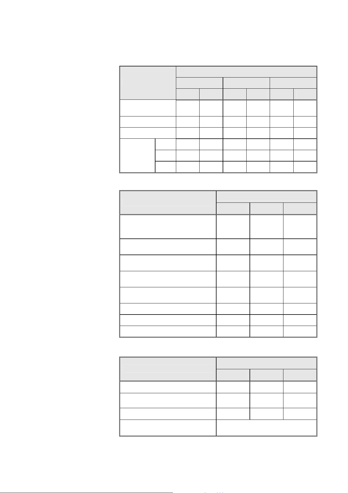
2.5 Specifications
h
2.5.1 Dimensions
MODEL
DIMENSIONS
2540 3850 3870
mm inch mm inch mm inch
Chamber
diameter
254 10.0 380 15.0 380 15.0
Chamber depth 419 16.5 480 19.9 680 26.8
Chamber volume 23 lit. 6.1 gal. 65 lit.17.2 gal. 85 lit.22.5 gal.
Height 643 25.3 745 29.4 925 3.4
Overall
dimensions
Width 496
Lengt
333 13.1 500 19.7 500 19.7
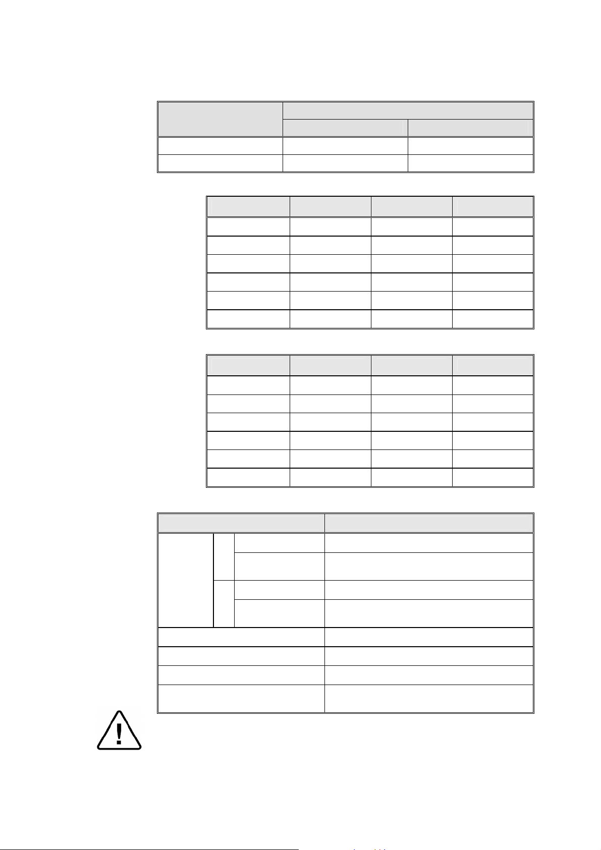
2.5.2 Technical Data
19.5
650 25.6 650 25.6
MODEL
PROPERTY
2540 3850 3870
Chamber material
Door material
Air supply pressure (ELVC only)
after pressure reducer - psi (Bar)
Feed water pressure (ELVC only)
after pressure reducer - psi (Bar)
Mineral free water pressure after
pressure reducer - psi (Bar)
St. St.
316 Ti
(1.4571)
ST.ST.
304L
45-58
(3.1-4.0)
17.4-26.1
(1.2-1.8)
17.4-26.1
(1.2-1.8)
St. St.
316 Ti
(1.4571)
ST.ST.
304L
45-58
(3.1-4.0)
17.4-26.1
(1.2-1.8)
17.4-26.1
(1.2-1.8)
St. St.
316 Ti
(1.4571)
ST.ST.
304L
45-58
(3.1-4.0)
17.4-26.1
(1.2-1.8)
17.4-26.1
(1.2-1.8)
Net weight lb (kg) 105 (48) 187 (85) 220 (100)
Shipping volume ft3 (m3) 7.1 (0.21) 19.8 (0.56) 19.8 (0.56)
Shipping weight lb (kg) 125 (57) 222 (101) 255 (116)
2.5.3 Electrical Data:
MODEL
PROPERTY
2540 3850 3870
Ampere 10A 15A 15A
Voltage
1Ph,
208V/60Hz
3Ph,
208V/60Hz
3Ph,
208V/60Hz
Power (Watts) 2400 W 6000 W 6000 W
Protection against electrical
shock
Page 8 of 51
Class I (IEC 60601-1)
2.6 Loading Capacities
Model
2540 10 liters 22 lb
3850/70 20 liters 44 lb
2.6.1 Erlenmeyer Flasks
SIZE 2540 3850 3870
250 ml 2 x 5 3 x 12 4 x 12
500 ml 2 x 4 2 x 7 3 x 7
1000 ml 1 2 x 4 2 x 4
2000 ml 1 3 2 x 3
3000 ml 1 2 2 x 2
5000 ml 1 1 1
2.6.2 Medium Flasks (Schott)
SIZE 2540 3850 3870
Maximum load
liquid instrument
250 ml. 2 x 8 3 x 18 4 x 18
500 ml 2 x 5 2 x 11 3 x 11
1000 ml 4 2 x 8 2 x 8
2000 ml 1 4 2 x 4
5000 ml 1 2 2
2.7 Utility
10000 ml
1 1
Utility Value
Power
Recommended
Electrical
data
2540
Circuit Breaker
Power
Recommended
3850/70
Circuit Breaker
Compressed Air (ELVC only)
Tap water (ELVC only)
Mineral free water
Drain
1/2", 60-120psi (4.1-8.3 Bar), 60 l/min
Must be able to withstand a minimum
1Ph, 208V/60Hz
20A
3 Ph, 208V/60Hz
3x20A
1/2", 30-45 psi (2.1-3.1 Bar)
1/2", 30-45 psi (2.1-3.1 Bar)
temp. of 190°F (88°C) min.
Attention:
The electrical net must be protected with a current leakage safety relay.
The electrical network must comply with local rules or regulations.
Page 9 of 51
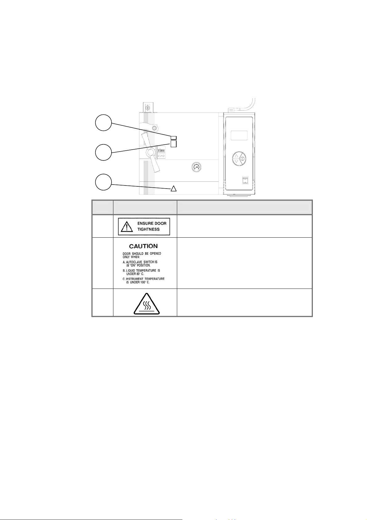
2.8 Marking
1
2
3
No. Marking Explanation
MARKING ON TOP VIEW
1
This sticker provides a safety instruction for
closing the door before beginning the cycle.
2
This sticker provides safety instructions for
opening the door at the end of the cycle.
3 The meaning of this symbol is “Caution, hot
surface!” It is to alert the user that the door
may be very hot.
Page 10 of 51
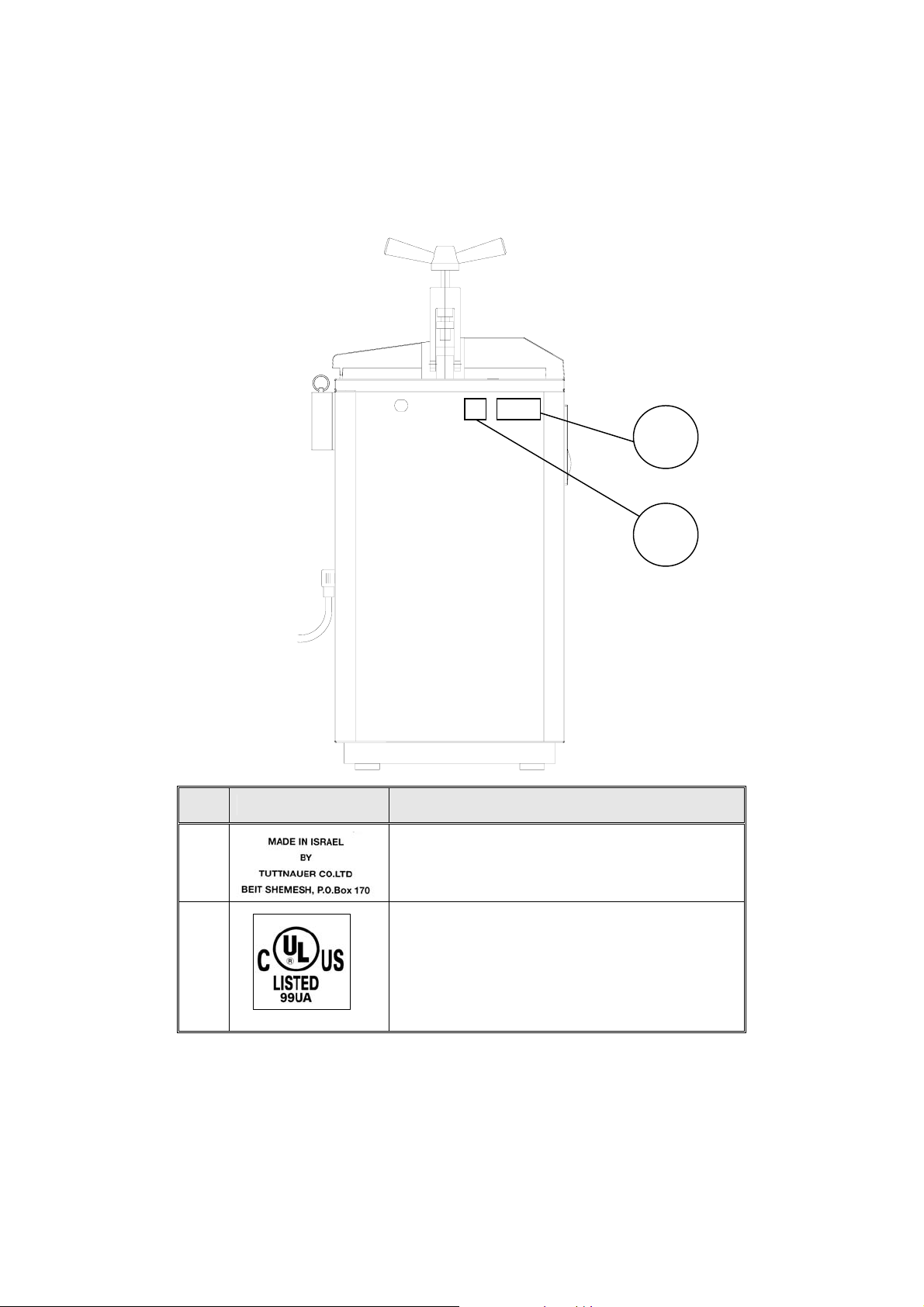
MARKING ON SIDE VIEW
1
2
No. Marking Explanation
1
This sticker provides the Manufacturer’s name
and address.
2
This sticker indicates that the autoclave is UL
and CSA approved.
Page 11 of 51
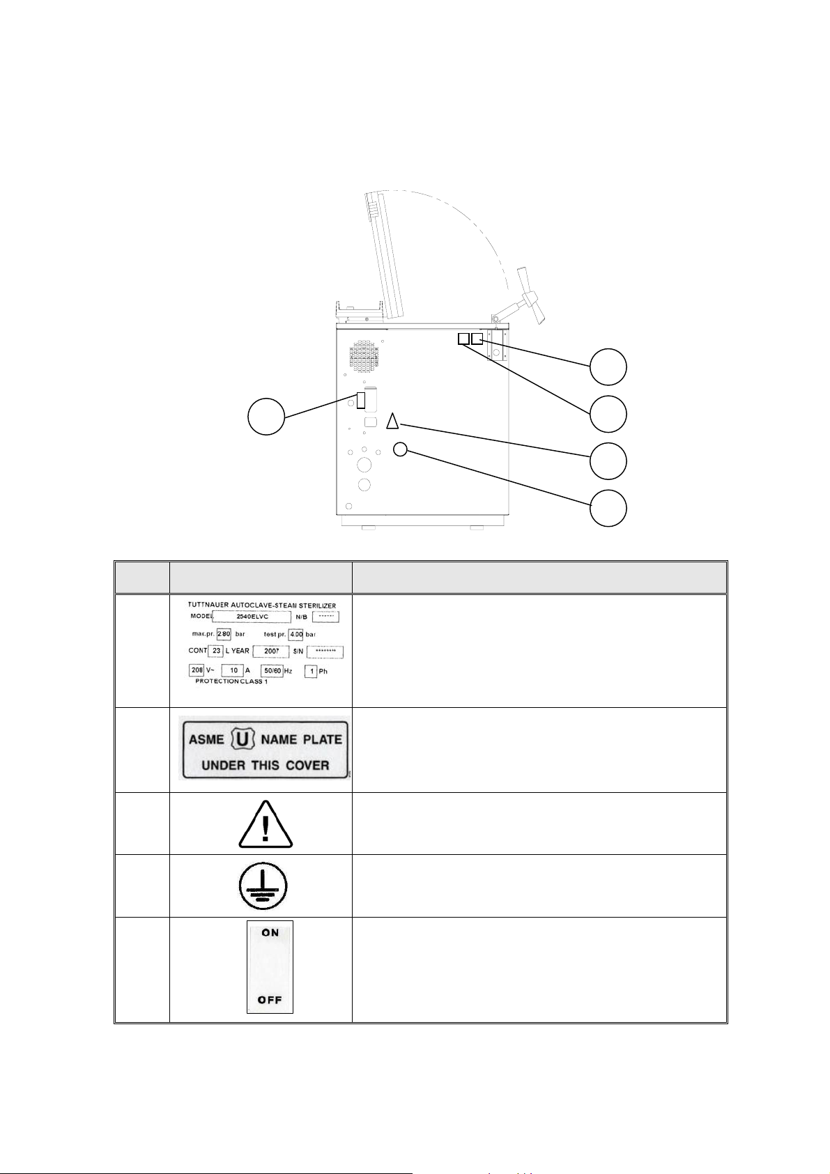
MARKING ON REAR VIEW
5
1
2
3
4
No. Marking Explanation
1 This sticker provides the following technical data:
1. Model name.
2. Nature of electrical supply.
3. Rated value of the supply voltage.
4. Maximum rated input current.
5. Autoclave's serial number.
2
This sticker indicates that the pressure vessel of the
autoclave is ASME approved.
3
The operator has to refer to the user manual.
4
5
This sticker indicated the place of the ground
connection to the body of the autoclave.
This sticker shows the on-position and the off-position
of the circuit breaker.
Page 12 of 51
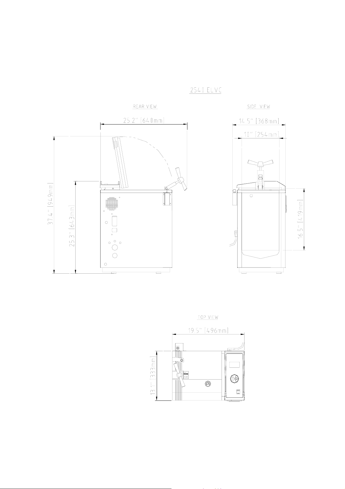
OVERALL DIMENSIONS DRAWING FOR 2540 ELV/ELVC
Page 13 of 51
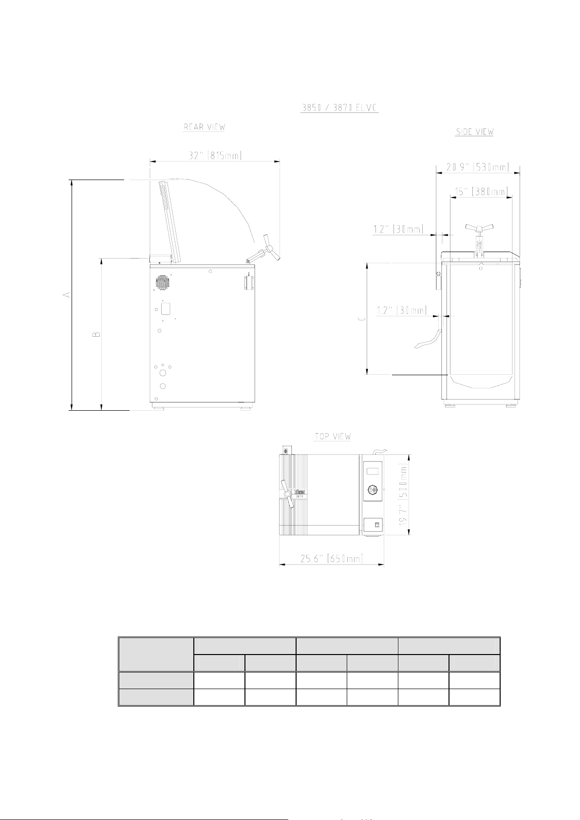
OVERALL DIMENSIONS DRAWING FOR 3850 / 3870 ELV/ELVC
Note:
The dimensions A, B and C are different for the models 3850 and 3870, as
indicated below
TYPE
A B C
mm inch mm inch mm inch
3850
3870
1220 48.0 745 29.4 480 19.9
1400 55.1 925 36.4 680 26.8
Page 14 of 51
 Loading...