

Tuttnauer E Series, 1730EK, 2340EK, 2540EK, 2340E Technical Manual
...
www.shanghaidelan.com
TECHNICIAN
MANUAL
E-type
models
Electronic
Table -Top Autoclaves
1730, 2340, 2540, 3140, 3850, 3870
E, EK, EA & EKA
Cat. No. MAN205-0064000EN Rev. H
Tuttnauer Europe b.v., Paardeweide 36, 4824 EH, Breda, P.O. Box 7191, 4800 GD Breda, Netherlands. +31/76-5423510, Fax:
+31/76-5423540

www.shanghaidelan.com

www.shanghaidelan.com
TABLE OF CONTENTS
PARAGRAPH PAGE NO.
1. INTRODUCTION .............................................................................................. 4
2. SYMBOL DESCRIPTION................................................................................. 4
3. TESTS ................................................................................................................ 5
3.1
3.2
4. WATER QUALITY ............................................................................................ 6
4.1. Water quality........................................................................................... 6
4.2. Reverse Osmosis ..................................................................................... 6
5. DESCRIPTION OF THE CONTROL SYSTEM............................................... 7
5.1
5.2
5.3
6. CALIBRATION OF TEMPERATURE AND PRESSURE............................. 11
6.1
6.2
6.3
7. TEST POINTS ................................................................................................. 15
8. SOFTWARE PROGRAMMING PROCEDURES........................................... 16
8.1
8.2
8.3
9. REPLACEMENT OF COMPONENTS........................................................... 21
9.1
9.2
9.3
9.4
9.5
9.6
9.7
9.8
9.9
9.10 Replacing the Cut-Off Thermostat ....................................................... 31
9.11 Cleaning and Replacing the Water Level Electrodes........................... 32
9.12 Replacing the Drain Valve.................................................................... 33
9.13 Replacing the Pressure Gauge ............................................................. 34
9.14 Replacing the Locking Solenoid........................................................... 35
9.15 Replacing the Printer............................................................................ 36
9.16 Replacing the Door Switch ................................................................... 38
9.17 Cleaning water inlet strainer................................................................ 39
Installation Tests .................................................................................... 5
Periodical Tests....................................................................................... 5
Digital Board DIG - T2........................................................................... 7
Analog Board ANL-T2 ........................................................................... 9
AC - Board - AC-T1.............................................................................. 10
Method of Calibration: ......................................................................... 11
Temperature Calibration Procedure .................................................... 12
Pressure Calibration Procedure ........................................................... 14
General ................................................................................................. 16
Changing Cycle Parameters ................................................................. 16
Resetting the Autoclave ........................................................................ 20
Safety Tests after Repair....................................................................... 21
Dismantling the Outer Covers of the Autoclave................................... 22
Replacing the Safety Valve ................................................................... 23
Replacing the Air Jet ............................................................................ 24
Replacing the Air Relief-safety relief Valve block ............................... 25
Replacing the electronics board (control panel) .................................. 26
Replacing the Electronics Box ............................................................. 26
Replacing Heating elements ................................................................. 29
Replacing the Temperature Safety Thermostat.................................... 30
1

www.shanghaidelan.com
9.18 Replacing the circuit breaker ............................................................... 40
9.19 Fuses and Circuit Breaker Data........................................................... 41
9.20 Replacing the water pump .................................................................... 42
9.21 Replacement of the Door Cover............................................................ 43
9.22 Replacing the Locking Device .............................................................. 44
9.23 Validation.............................................................................................. 45
9.24 Emergency Door Opening .................................................................... 46
10. IN-OUT TEST.................................................................................................. 47
11. TROUBLESHOOTING ................................................................................... 48
11.1 Displayed Messages and Reference to Trouble Shooting .................... 48
11.2 Pre-process malfunction....................................................................... 49
11.3 In Process Malfunction ........................................................................ 54
11.4 Mechanical malfunction....................................................................... 69
11.5 Water pump malfunction...................................................................... 70
12. LIST OF SPARE PARTS................................................................................. 71
13. PRESSURE VS TEMPERATURE FOR SATURATED STEAM ................... 82
14. XPCS Manual .................................................................................................. 86
15. VALVES NUMBERING.................................................................................. 99
2

www.shanghaidelan.com
TABLE OF CONTENT (cont.)
DRAWINGS PAGE NO.
Control System Block-Diagram...................................................................................7
DIG- T2 Board ............................................................................................................8
ANL - T2 Board........................................................................................................... 9
AC-T1 Board .............................................................................................................10
Front View................................................................................................................. 76
Vessel Assembly......................................................................................................... 78
Door Tightening Bolt – Assembly ............................................................................. 79
Outer Cabinet - Assembly.......................................................................................... 80
Water Outlet Strainer ................................................................................................ 81
Electrical Wiring Diagram: Models: 1730 120/230V ............................................ 103
Electrical Wiring Diagram: Models: 1730 120/230V .............................................104
Electrical Wiring Diagram: Models: 2340/2540E 120/230V.................................. 105
Electrical Wiring Diagram: Models: 2340/2540EA 120/230V ............................... 106
Electrical Wiring Diagram: Models: 3140E 230V.................................................. 107
Electrical Wiring Diagram: Models: 3870/3850E 120/230V.................................. 108
Electrical Wiring Diagram: Models: 3870/3850EA 120/230V ............................... 109
3
www.shanghaidelan.com
1. INTRODUCTION
This manual, together with the operator’s manual, forms the complete edition of
the Operation and Maintenance instructions. This manual is intended for the use
of the technician. It is forbidden for unqualified and unauthorized personnel to
service the autoclave in accordance with the instructions in this manual. Any
unauthorized service may result in the invalidation of the manufacturer’s
guarantee.
The qualified technician shall be an authorized electrician with the right
qualifications in electronics and shall be familiar with the local
technical/electrical regulations.
2. SYMBOL DESCRIPTION
Caution! Consult accompanying documents
Caution! Hot surface.
Caution! Hot steam.
Protective earth (Ground)
On-Off
4
www.shanghaidelan.com
3. TESTS
3.1 Installation Tests
The service technician shall perform the following preliminary checks
before operating the autoclave:
a. Integrity Check
Perform a visual check to verify that there are no dents, scratches,
b Leveling Check
Check that the autoclave is leveled.
c. Leakage current test
Check the precise operation of the earth leakage relay.
d. Continuity Check
Check the continuity of the grounding connection.
At this stage operate the autoclave and continue with the tests:
e. Safety Check
Check the safety elements; safety valve and the door locking
f. Programs Check
Run basic programs of the autoclave and check the operation
g. Validation
Validate the sterilization cycles, taking in consideration the interface
After the above steps are performed, the autoclave is ready for operation.
broken gauges, etc.
mechanisms.
sequences, the sterilization parameters etc.
of packaging/goods/autoclave.
3.2 Periodical Tests
PERIOD
1 months Test the safety valve by operating it.
Remove the cover of the autoclave, tighten the screws of the
6 months
Year
5 years Observe the closing device for excessive wear
Safety tests (pressure vessel, efficiency, electrical) shall be performed in
accordance with local rules or regulations, by an authorised inspector.
heaters and the electrical connections at the heaters, valves
and connectors in the control box.
Check the continuity of the grounding connections.
Check the temperature and pressure calibration.
Perform validation of the autoclave.
Check the precise operation of the earth leakage relay.
Check that the autoclave is levelled.
Check the safety elements; safety valve, safety and cut-off
thermostats door locking mechanisms.
Run basic programs of the autoclave and check the operation
sequences, the sterilization parameters etc.
Check the water reservoir, piping, plastic parts and electric
wires.
Check and tighten the piping joints to avoid leakage.
Check and tighten all screw connections in the control box,
heaters and valves and instrumentation.
TEST
Only an authorized technician shall perform the 6-months and yearly
tests!
5
www.shanghaidelan.com
4. WATER QUALITY
4.1. Water quality
The distilled or mineral – free water supplied to the sterlizer shall be
according to the table below:
Physical Characteristics and Maximum acceptable contaminants levels
Evaporate residue ≤ 10 mg/l
Silicate (SiO2) ≤ 1 mg/l
Iron ≤ 0.2mg/l
Cadmium ≤ 0.005 mg/l
Lead ≤ 0.05 mg/l
Rest of heavy metals except iron,
cadmium, lead
Chloride (Cl) ≤ 2 mg/l
Phosphate (P2O5) ≤ 0.5 mg/l
Conductivity (at 25°C) ≤ 15 µs/cm
pH value (degree of acidity) 5 to 7.5
Hardness (Σ ions of alkaline earth) ≤ 0.02 mmol/l
Appearance
Compliance with the above data should be tested in accordance with
acknowledged analytical methods, by an authorized laboratory.
Attention:
We recommend testing the water quality once a month. The use of
water that does not comply with the table above may have severe impact
on the working life of the sterilizer and can invalidate the
manufacturer’s guarantee.
4.2. Reverse Osmosis
A Reverse Osmosis system may be used to improve the quality of the
water used to generate steam in the autoclave chamber. The use of
mineral free will contribute to better performance and longer life of the
autoclave.
in water or steam for sterilizers
(According to EN 285:2006).
≤ 0.1 mg/l
Colourless, clean, without
sediments
6
www.shanghaidelan.com
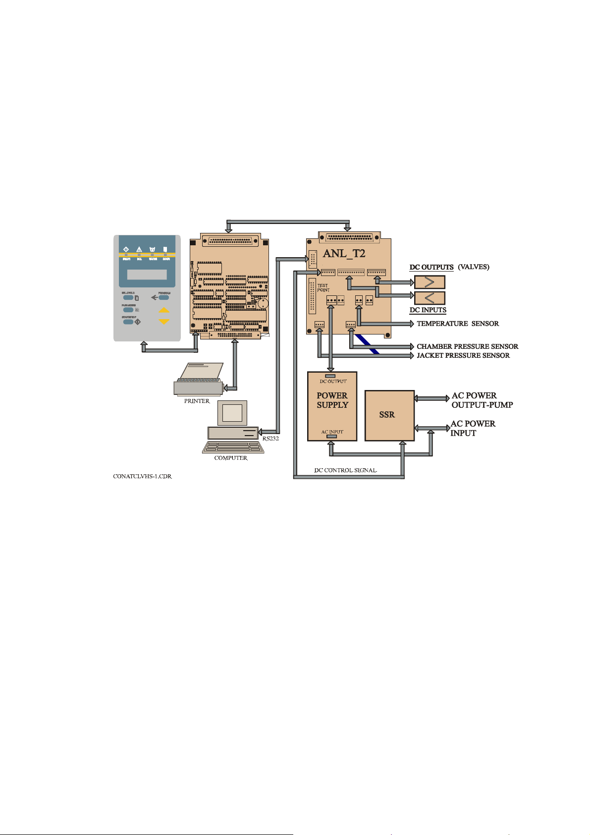
5. DESCRIPTION OF THE CONTROL SYSTEM.
(See CDR Control diagram).
The control system is based on 3 electronic boards designed according to the
autoclave requirements, the digital board DIG-T2 containing the microcontroller memories, buffers and digital ICs and the analog board ANL-T2
which performs the processing of signals coming from the sensors and switches.
The AC-T1 board consists of filters and AC drivers. DC voltages 12V and 5V,
supplied by a switching type power supply, powers the 3 electronic boards.
CONTROL SYSTEM BLOCK-DIAGRAM
PLUG
SKT
20
1
DIG-T2 BOARD
C2
+
U12
R3
C9
R2
U16
R1
U11
U14
C5
U21
U17
DIG T3
U22
97-05
C24
C25
8
C23
1
JP3
C22
2
DS1
1
37
JP1
19
U8
U3
C3
+
RP1
U15
R9
D1
C15
U1
C7
U18
C4
R4
U4
C16
C17
Q1
Y1
BZ1
U19
C6
34
33
20
1
P1
1
JP7
JP2
JP3
1
1
JP12
1
37
19
JP1
12
1
JP6
JP5
JP4
1
JP8
1
1
JP9
JP10
1
The system is provided with communication interfaces RS 232 to PC and to
parallel printer.
5.1 Digital Board DIG - T2
— The digital board is connected to the keypad panel, to the parallel
printer and to the analog board ANL-T2.
— The board contains the micro-controller (U15) type 80C32 that runs
the software program of the system.
— On the board, are three types of memories:
1) EPROM memory (U17), part no. 27512 storing the program
codes.
2) RAM memory (U21) with a capacity of 32KB for the temporary
data during the running of the program.
3) EPROM memory (U22) that is a fixed serial memory with an
electrical writing and erasing.
— This EPROM serves as a non-volatile memory, enabling the system
to change follow-up tables during running of program codes, and
ensuring this data is not lost in case of power failure.
7
www.shanghaidelan.com
— The board contains an optimal Real Time Clock (U12), which serves
as a clock to the system, including a back-up battery, which ensures
the clock, runs continuously even when the autoclave is not
powered.
This component is optimal because it is related to the operation of
the printer, which is also an optional item.
— The board contains a watchdog, which detects any faulty situation in
the running program code. It performs an automatic reset of the
micro-controller and stops all the commands to avoid an
uncontrolled activation of any of the heating elements or the valves.
— The board functions as an MMI (Man-Machine Interface). It is
connected to a LCD display of two rows with 16 characters on each
row and to the following light indicators:
— START (autoclave in process),
— FAIL (the process failed),
— WATER (no water in the reservoir),
— DOOR (the door is not closed).
A keyboard connected to the digital board, serves as a control panel
containing the command and programming keys.
— The digital inputs and outputs are transferred to the system, as
follows:
— Through the digital board to the analog board by means of buffers
74HC377.
— RS232 interface is performed on the board by the U13 component,
the signal is transmitted to the communication connector located on
the ANL-T2 board.
— The printer is connected directly to this board, connector DS1
enables to connect the DPU-20 printer manufactured by SEIKO.
The printer receives the data and the supply voltage directly from
this connector.
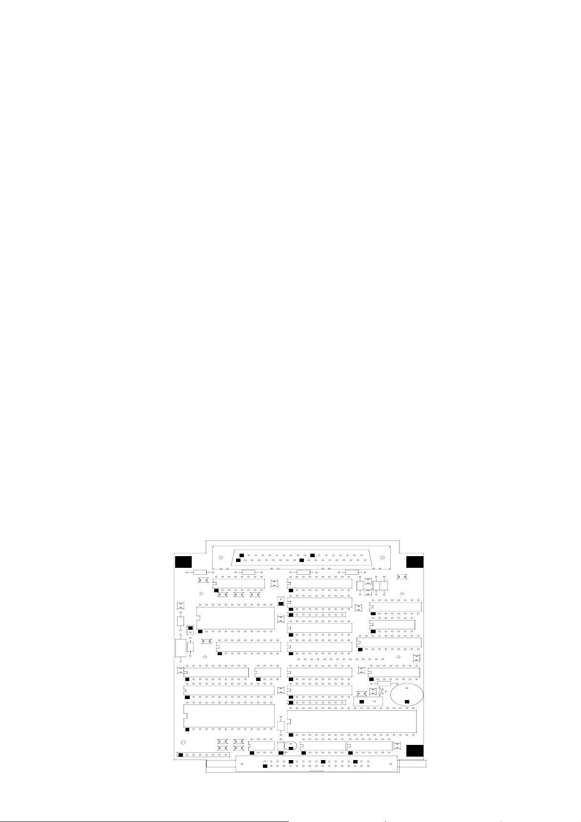
The layout of the DIG-T2 board components is provided below
DIG- T2 BOARD
SK
+
C5
C2
R3
R1
C1
R2
R8
U1
U1
C1
C9
U1
U1
20
1
R7 R6
C1
U1
C1
C1
U5
U1
JP
C8
U7
R5
RP
U8
U3
C1
R1
U6
C4
37
19
+
U2
C1
C2
R1
U1
JP1
C2
R1
U2
C7
R4
U2
U1
H2
1
DIG
97-05
JP3
C2
C2
+
C3
RP
U1
R9
U2
C2
8
C2
DS
D1
C1
2
1
U1
Y1
U4
C1
C1
Q1
BZ1
U1
C6
34
33
8
www.shanghaidelan.com
5.2 Analog Board ANL-T2
The analog board contains the drivers of the valves, heaters and pump. It
contains the sensors circuits connected to the control system, and serves
as a junction to the autoclave connections.
The input is 12VDC & 5VDC and the output is for all the signals to the
autoclave.
— The power supply provides the DC voltages 12V and 5V through the
connector JP3 to the board and further to the DIG-T2 board.
— The computer is connected to the board through the connector P1, by
RS232 interface.
— The analog and digital inputs, from the temperature sensor, electrode
door switch, etc. are connected through connector JP6, the
conversion circuits of the sensors are located on this board.
— The pressure sensor MPX2200 that measures the chamber pressure is
connected to the board through connector JP8, to the conversion
circuit of the sensor that is located on this board.
— The analog to digital conversion circuit A/D (U5) and the analog
multiplexer (U6) for 8 analog inputs (temperature, pressure, and
electrode) are located on this board and transfer digital signal to the
DIG-T2 board.
— All the drivers and power circuits to the solenoids (valves, door
locking) are included on this board.
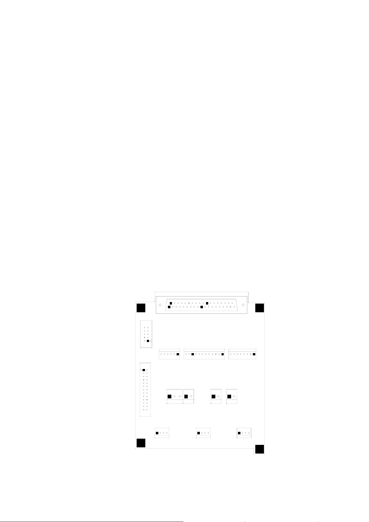
Layout diagram of the ANL-T2 is provided below.
ANL - T2 BOARD
PLUG
P1
JP2
JP12 JP8
1
ANL T1 BOARD
20
1
JP1
1211
1
JP4
JP5
JP9
1
1
JP7
JP3
1
1
37
19
JP6
JP10
1
JP11
1
9
www.shanghaidelan.com
5.3 AC - Board - AC-T1
This board receives command signals from ANL-T2 board designated to
activate AC devices. It converts them to AC mode.
The AC-T1 board provides AC filtering for the power supply to the
control system and protection from sharp current fluctuations.
The AC-T1 board includes:
— AC drivers for the AC devices (pump, heaters, etc.) up to 6A.
— AC - input connector JP3.
— Filter circuit based on L1C5, the power transfer from the filter to
power supply via JP2.
— Spike protection - RV1÷3.
— Three - 230/115 VAC output channels, triac control circuit.
Q1 - 16Amp - JP4/1,2
Q2 - 8 Amp - JP7/1
Q3 - 8 Amp - JP7/2
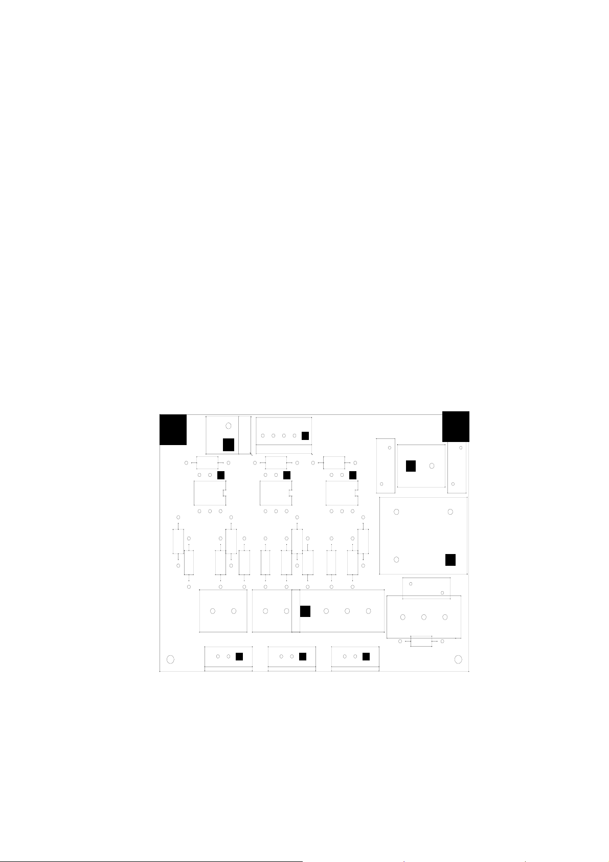
AC-T1 BOARD
(JP3,JP4,JP7 ON THE BOTTOM SIDE OF THE BOARD)
JP5
R9
U3
R12
C3
Q3
R11
JP7
1
R10
R8 C2
U2
JP1
R5
R6
R7 C1
R4
JP4
1
Q2
1
U1
R1
Q1
R3
RV3 RV2
JP2
R2
L1
JP6
JP3
C5
ETYPEAC-97
CAT TECH.
RV1
10
www.shanghaidelan.com
6. CALIBRATION OF TEMPERATURE AND PRESSURE
6.1 Method of Calibration:
The calibration of temperature and pressure is performed digitally.
The temperature and pressure measuring circuits are designed with
components having 1% accuracy.
The temperature circuit is linear and has an output of 100mV÷2400mV
for a temperature range 20°C÷150°C.
The pressure circuit is also linear and has an output of 100mV÷2400mV
for a pressure range 0÷400 kPa.
The measuring at the A/D is limited for values higher than 2400mV or
below 100mV.
The system has a non-volatile memory in which the offset and gain data
of the sensors are stored.
Calibration is performed by use of the keyboard (or the communication
port for computer use).
Following is a description of the calibration of temperature and pressure
using the keyboard. The calibration procedure is identical to all autoclave
models.
Definition of Gain and Offset:
Every straight line can be defined by the equation ax+b=y. “a” is the
deviation from y=0 and “b” is the slope of the line. In our case a=Gain
and b=Offset.
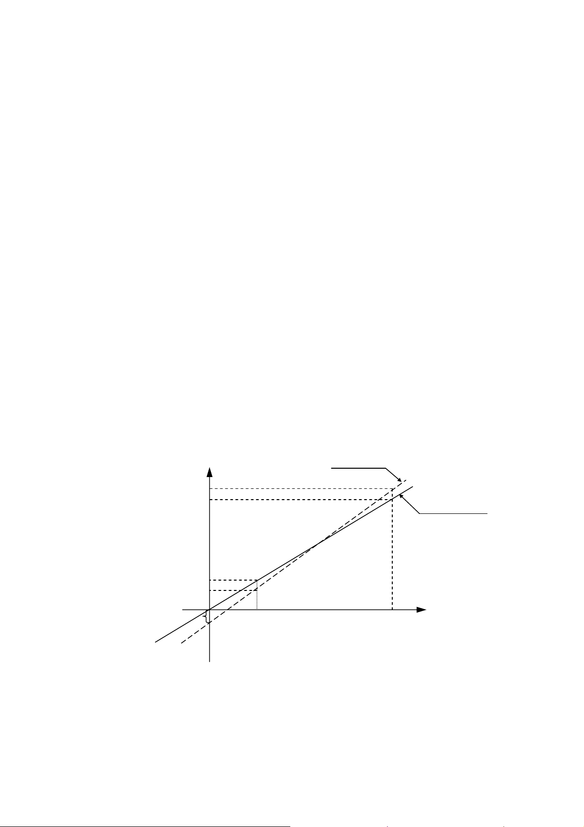
The system is based on calculation of offset and gain of two points as in
the following example
If the actual measured pressures are 100 kPa & 300 kPa and the
displayed pressures are 90 kPa & 310 kPa respectively, the ‘input Vs
pressure” graph will be as follows.
READ
310
300
Y
ACTUAL
100
90
PRESURE
a
V
1
X
INPUT FROM SENSOR
V
2
The calibration method enables to input this data into the system in order
to perform automatic correction of OFFSET and GAIN.
It is necessary to define the two points, which have to be input to the
system, prior to performing calibration.
11

www.shanghaidelan.com
6.2 Temperature Calibration Procedure
— Press the PROGRAM
— The system enables to set the system’s date the time.
— This operation is skipped by pressing PROGRAM key
six times.
— CODE: ∅∅∅ will be displayed.
— Select Technician Code (011) by the UP/DN keys and press the
PROGRAM
— Select CALIB CODE: 107 to calibrate the system by means of the
UP/DN keys and press the PROGRAM key again until TEMP
CAL: ∅∅∅ will be displayed.
— Set calibration code to TEMP CAL: ∅∅1
— Press the PROGRAM
— The following data will be displayed:
UPPER ROW: A 60.0 R 60.0
LOWER ROW: A 130.0 R130.0
Enter the actual data (A) and the displayed data (R) for two known points
as in the following example:
The actual temperatures are 70°C & 120°C and the displayed
temperatures are 68°C & 120°C respectively.
Proceed as follows:
— On the upper row, change A60.0 to A 70.0 by means of UP/DN
keys.
key.
key.
key again and do not change the code.
— Press the PROGRAM
— The cursor on the upper row will move to R60.0, change to R68.0 by
means of UP/DN keys.
— Press the PROGRAM
— The cursor moves to the lower row to A 130.0
by means of UP/DN keys.
— Press the PROGRAM
— The cursor on the lower row will move to R130.0, change to R123.0
by means of keys UP/DN, then press the PROGRAM
This completes calibration procedure for temperature.
key.
key.
, change it to A 120.0
key.
key
12

www.shanghaidelan.com
Remarks:
— When cursor is set under any figure, pressing the START/STOP
key stops calibration.
— When the cursor is set under any figure, it enables to feed this value
to the reading of temperature by pressing the PARAMETERS key.
Example:
If the cursor is set under R68.0 on the upper row and the actual
temperature of the autoclave is now 66.0ºC, by pressing the
PARAMETERS
R68.0 to R 66.0.
This calibration method enables the technician to change a certain point
without affecting a second point.
Example:
When the working temperatures are 134ºC and 121ºC but the actual
temperature are 132ºC and 121ºC
The measured temperature for 134ºC must be corrected without
changing the temperature at 121ºC,
Considering the above example, the setting of data can be done as
follows:
A 121.0 R 121.0
A 132.0 R 134.0
The system will calibrate the new offset and gain and retain them into the
non-erasable memory.
As a result, while running a 134ºC program the correction is
automatically made, while at 121ºC no change is felt.
key, the temperature reading will be corrected from
13

www.shanghaidelan.com
6.3 Pressure Calibration Procedure
To perform the pressure calibration two points have to be defined
allowing the calculation of new OFFSET and GAIN values.
— Press the PROGRAM
key.
— Skip date and the time setting by pressing the PROGRAM key
six times.
— CODE: ∅∅∅ will be displayed.
— Select the Technician Code (011) by the UP/DN keys and press the
PROGRAM
key.
— Select CALIB CODE: 107 to calibrate the system by means of the
UP/DN keys and press the PROGRAM key again until the
system displays: PRES CAL: ∅∅∅
— Press the PROGRAM
key.
The following is displayed:
Point 1 – Upper Row A 100 R 100
Point 2 - Lower Row A 300 R 300
— Open the door, do not alter A 100.
— Press the PROGRAM key, the cursor will move to R
100.
— Press the PARAMETERS key. The system performs reading
pressure and displays it instead of R100. E.g. R97 (i.e. the system
reads out 97kPa, when the door is open).
— Press the PROGRAM
key.
— The cursor moves to the lower row to A300.
If the system reads out 280kPa, do not change A300. Press the
PROGRAM
key to move to R300 and change it to the actual
pressure value 280kPa by means of the keys UP/DN.
— Press the PROGRAM
key again.
The system calculates the new values for offset and gain and stores
these values in the non-volatile memory.
This completes the calibration procedure for the pressure.
14
www.shanghaidelan.com
7. TEST POINTS
The test point list provides testing points on the junctions on board to assist in
locating the malfunction.
NU TP FUNCTION VALVE
TP1
TP2
TP3
TP4
TP5
TP6
TP7
TP8
TP9
TP10
TP11
TP12
TP13
TP14
TP15
GND
+5V DC
+12V DC
OUT - HEATERS ‘0’V-Off 5V-On
OUT-AIR-VALVE 0V-Off 5V-On
OUT-EXH-VALVE 0V-Off 5V-On
OUT-WATER-VALVE 0V-Off 5V-On
OUT-DRY-VALVE 0V-Off 5V-On
OUT-DOOR-VALVE 0V-Off 5V-On
TP16
TP17
TP 18
TP19
TP20
TP21
TP22
TP23
TP24
TP25
TP26
IN-TEMPERATURE
0÷2.5V
IN-PRESSURE
IN-ELECTR. 2.5V NO WATER
0 ÷2.5V
15

www.shanghaidelan.com
8. SOFTWARE PROGRAMMING PROCEDURES
8.1 General
The software for the control system of E-Type autoclaves is AS
FOLLWS:
EaEn3WP20 for standard autoclaves.
EaEn3WP20AR for autoclaves designed to operate at high altitude
(above 2500 m.
The software contains a table of parameters of which part of them defines
the autoclave, and part defines the processes in the autoclave. This
document describes parameters and their task in the software.
8.2 Changing Cycle Parameters
Access to the program is achieved by inserting the access code.
Access code 1 – This access code enables change of the sterilization
time, sterilization temperature and the drying time.
Access code 11 – changes that may be done by the supervisor.
Enables to change a few parameters
Access code 33 – changes that may be done by the technician.
Enables to change all the parameters
To change the parameters listed below, proceed as follows:
a. Select the cycle.
b. Enable the operation by entering the ACCESS CODE (11).
c. Set the parameter that has to be modified, by pressing successively
the PROGRAM key.
d. Set the desired data by means of the UP/DN keys.
e. Pressing the PROGRAM key enters the modified data into memory,
and moves to the next parameter.
The pre-set parameters values will replace the last default values and
become the updated default values.
8.2.1 SteTemp – Required sterilization temperature for the process
Entry Code – 1
Resolution – 1ºC
Minimum value for the change – 60ºC
Maximum value for the change – 137ºC
Set value
Cycle
Value
8.2.2 SteTime – Required sterilization time for the process
Entry code – 1
1 2 3 4 5
134 121 134 121 121
Resolution – 1 minute
Minimum value – 3 minutes
Maximum value – 99 minutes
Set value
Cycle
Value
1 2 3 4 5
3 15 7 20 30
16

www.shanghaidelan.com
8.2.3 Heat Standby – Heating elements operation in Standby Mode
Access Code – 1
Resolution – 1
Value – 0 or 1
— If Heat Standby = 0, the heating elements will not
operate in the Standby Mode.
— If Heat Standby = 1, the heating elements will operate in
the Standby mode, in a shoot mode of 1 second on, 59
seconds off.
8.2.4 Dry Time – Required drying time for the process
Entry Code – 1
Resolution – 1 minute
Minimum Value – Ø minutes
Maximum Value – 99 minutes
Cycle
Set value
8.2.5 Heat T.O. - Maximum time allowed for the heating stage
(testing)
After this time, if the system does not enter the sterilization stage,
it will receive a ‘Low Heat’ message and the process will abort.
Entry Code – 11
Resolution – 1min
Minimum Value – 20min
Maximum Value – 120 min
Set value
8.2.6 Ex Mode – The method for exhausting the steam at the end
of the process
Entry Code – 11
Value
per
model
Cycle
Value
E, EK
EA, EKA
1 2 3 4 5
60 60 60 60 90
1 2 3 4 5
0 0 30 30 0
1 1 30 30 0
Resolution – 1
Ex Mode
Fast Ex 1
N.A. 2
Slow Ex (Waste) 3
Slow Ex (Liquids) 4
Set value
Cycle
Value
1 2 3 4 5
1 1 1 1 4
17

www.shanghaidelan.com
8.2.7 End Temp - The ending temperature of the process
If at the end of the process the temperature is higher than this
temperature, the process will not end and the door will remain
closed.
Entry Code – 11
Resolution – 1ºC
Minimum Value – 40ºC
Maximum value – 137ºC
Set value
Cycle
Value
8.2.8 Air Temp – Controls the closing of the air valve
Defines the temperature of the chamber’s outlet at which the
valve closes.
Access Code - 11
Resolution - 1
Minimum Value - 50°C
Maximum Value - 99°C
Factory pre-set 90°C
Cycle
Set value
Value
8.2.9 Calib Code – Calibration Code
This allows entry to the calibration mode.
It must be set on 107 in order to allow the code to be entered.
1 2 3 4 5
125 121 125 134 95
1 2 3 4 5
90 90 90 90 90
Entry Code – 11
Resolution – 1
Minimum Value – Ø
Maximum Value – 255
Set value
Cycle
Value
1 2 3 4 5
100 100 100 100 100
18
www.shanghaidelan.com
8.2.10 Water Time – Time for entering water to the autoclave
This value defines the entry time of the water to the autoclave to
locate the electrode touching the water.
This time will change from process to process and even for
different autoclaves.
When the autoclave is vertical and the defined time is Ø
seconds, the water valve will not open at all.
Entry Code – 11
Resolution – 1 second
Minimum Value – 1 second
Maximum Value – 90 seconds
Cycle
1730
2340
Set value
8.2.11 LimitP add – The allowable addition to the maximum
pressure in every process
If the maximum pressure is 225kpa, the system will not heat
beyond this pressure. If LimitP add will be Ø, the maximum
pressure will remain 225kpa. If LimitP add equals 10, the
maximum pressure will be 235kpa.
Entry Code – 11
Resolution – 1kpa
Minimum Value – Økpa
Maximum Value – 30kpa
Value
per
model
2540
3140
3850
3870
1 2 3 4 5
50 50 50 50 50
30 30 30 30 30
40 40 40 40 40
45 45 45 45 45
60 60 60 60 60
Set value
8.2.12 EA Type – The autoclave contains a drying pump for the Dry
Stage
Access Code – 33
Resolution – 1
Value – 0 or 1
Autoclave contains Drying Pump = 1
Autoclave does not contain a Drying Pump = 0
Set value
Cycle
Value
Cycle
Value
per
model
1 2 3 4 5
0 0 0 0 0
1 2 3 4 5
E, EK
EA, EKA
19
0 0 0 0 0
1 0 0 0 0

www.shanghaidelan.com
8.2.13 Req Prs+
This defines the required addition to the sterilization pressure in
kpa.
For example, for a sterilization temperature of 121ºC the
required pressure is 204kpa. Since the system controls the
sterilization process according to pressure and temperature, if
Req Prs+ equals Ø, the system will maintain the pressure at
204kpa. If the value is at 5kpa, the system will be maintained at
209kpa, and so on.
Entry Code – 33
Resolution – 1
Minimum Value – 0kpa
Maximum Value – 15kpa
Cycle
1730
Set value
8.2.14 Auto. Num – Autoclave serial number
This parameter is used to set the serial number in the facility.
This number enables the operator to identify each autoclave.
This number is printed on the autoclave’s printout.
Access Code – 13
Resolution – 1
Minimum Value – 1
Maximum Value – 99
8.3 Resetting the Autoclave
Whenever certain data, stored in the back-up memory, must be erased the
system must be reset, in order to restore the system to normal operation
or for situations that follow:
Value
per
model
2340
2540
3140
3850
3870
1 2 3 4 5
7 5 7 5 5
9 9 9 9 9
— When the machine is operated for the first time or after a long
interruption, and disorders appear in the operations sequence.
— When operation was stopped in the middle of the cycle, as a result of
a power failure or manual stop and the cycle has not been completed.
To reset the system; proceed as follows:
— Turn the main power switch OFF.
— Turn the main power switch ON, while pressing the SEL. CYCLE
key, until the program parameters are displayed.
After resetting the autoclave, the autoclave is in stand-by mode
20

www.shanghaidelan.com
9. REPLACEMENT OF COMPONENTS
9.1 Safety Tests after Repair
ATTENTION!
After every repair or dismantling the enclosure, the autoclave should
pass two safety electrical test by the Service Engineer. The following
shall be performed:
1. Enclosure Leakage Current Test.
Every autoclave should pass this test as follows:
1. Remove the outer cover (see para. 9.2 “Dismantling the Outer
Covers of the Autoclave”).
2. Disconnect receptacle from JP3.
3. Remove all fuses
4. Connect the electrical cord to the autoclave.
5. Turn on the circuit breaker.
6. Short-circuit the L and N pins on the cord's plug.
7. Connect the Short-circuit pins to the L pole on the Megger.
8. Connect the earth pins to the earth pole on the Megger.
9. Impose an electrical potential of 500-1000V on the tested
autoclave. The insulation resistance should be at least 2 MΩ.
The test is successful if there was no leakage.
2. Protective Earth Impedance Test
1. Connect the grounding pin of the power cord plug to one pole of
an Ohmmeter.
2. Connect any other metallic part (preferable – the metallic part of
the locking screw) to the second pole of the Ohmmeter.
3. The resistance should not exceed 0.3 Ω.
After performing these tests, the Service Engineer should complete and
sign the Work Order.
21
www.shanghaidelan.com
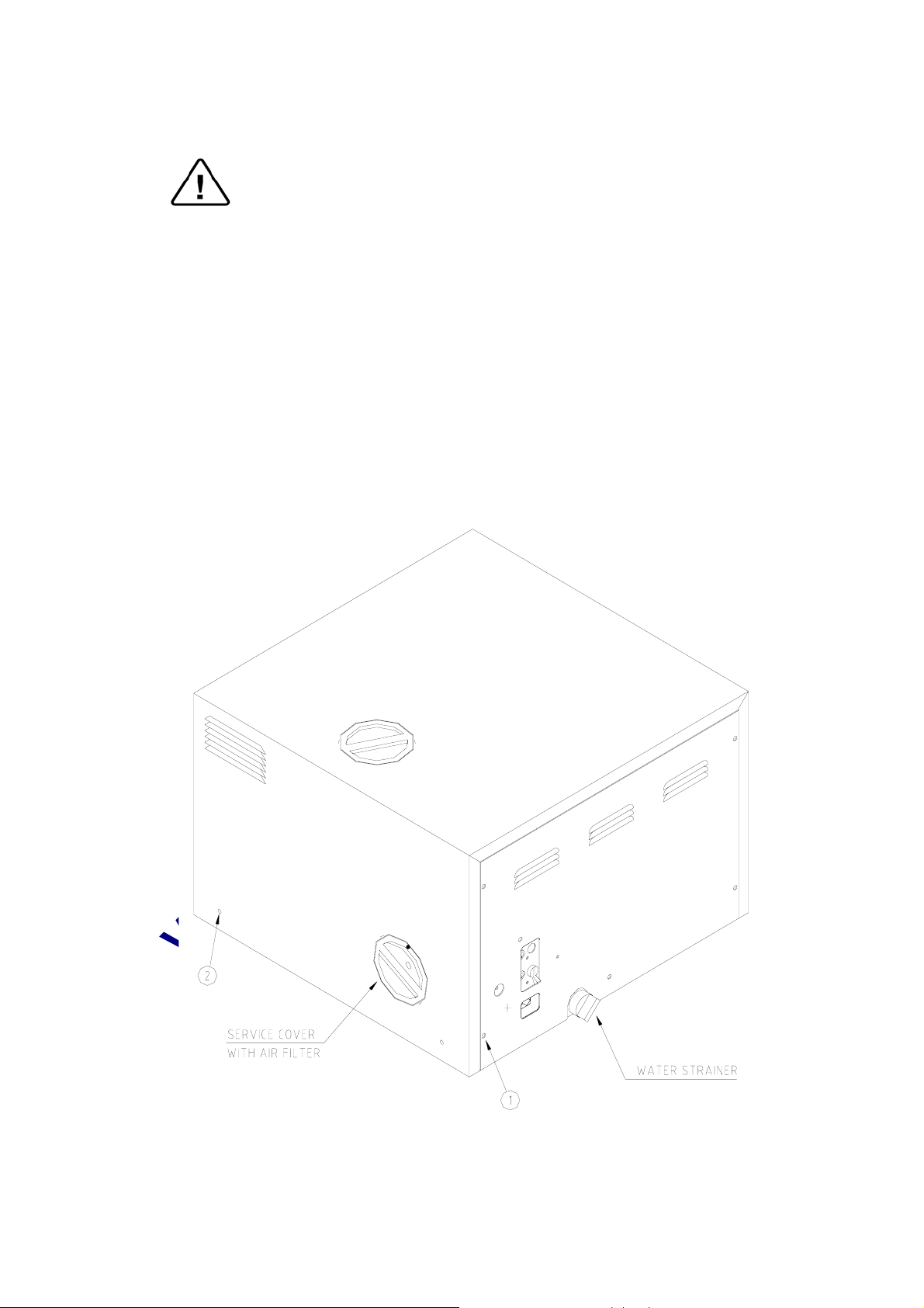
9.2 Dismantling the Outer Covers of the Autoclave
Caution!
Before starting, disconnect the instrument from the power source and
ensure that there is no pressure in the autoclave.
Allow the autoclave to cool before removing outer covers.
1. Remove the screws holding the rear cover (1).
2. Remove the screws holding the cover to the base (2).
3. On EA and EKA models dismantle the air filter from the service
opening cover (3).
3.1. Remove the screws holding the filter cover (on EA, EKA).
4. Remove the grounding wires from the cover.
5. Pull the cover upwards.
22
www.shanghaidelan.com
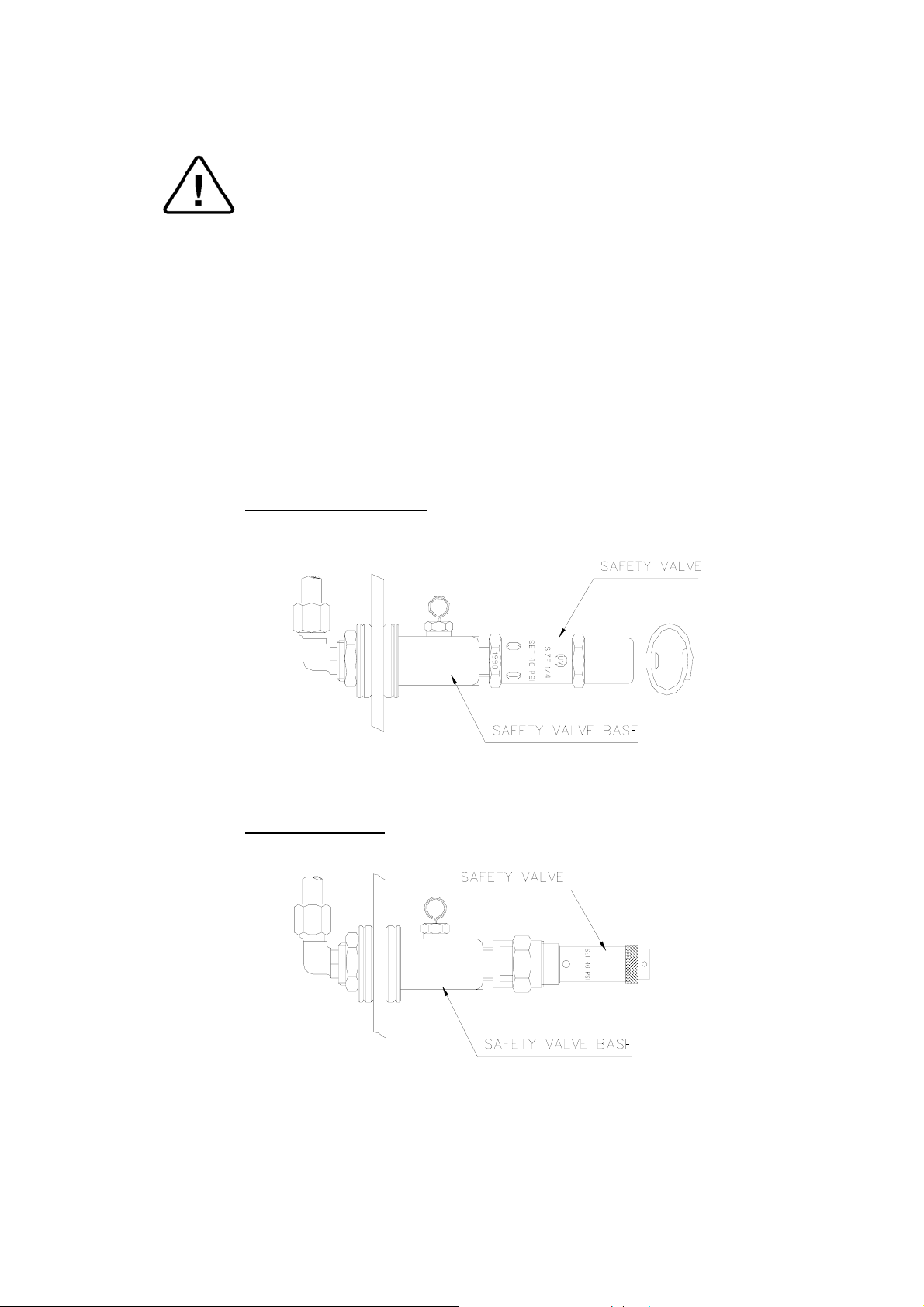
9.3 Replacing the Safety Valve
Caution!
Before starting, be sure that the electric cord is disconnected and that
there is no pressure in the autoclave.
Note:
These instructions are valid for both, PED and ASME type safety
valves.
1. Remove the autoclave cover (see para. 9.2 “Dismantling the Outer
Covers of the Autoclave”).
2. Remove the water reservoir cover.
3. Unscrew the safety valve and remove it from the safety valve base.
4. Replace the valve with a new safety valve (install an original only!).
use Teflon tape for sealing the thread.
5. Perform one cycle and verify that the valve operates correctly.
ASME approved Type
CE marked Type
23

www.shanghaidelan.com
9.4 Replacing the Air Jet
Caution!
Before starting, be sure that the electric cord is disconnected and that
there is no pressure in the autoclave.
1. Remove the autoclave cover (see para. 9.2 “Dismantling the Outer
Covers of the Autoclave”).
2. Remove the water reservoir cover.
3. Remove the water reservoir silicon gasket.
4. Unscrew the air Jet with a 10 mm wrench and remove it from the
safety valve base.
5. Replace the valve with a new air Jet (install an original only!). use
Teflon tape for sealing the thread.
6. Test any autoclave cycle to verify that the valve operates correctly.
AIR JET
24

www.shanghaidelan.com
9.5 Replacing the Air Relief-safety relief Valve block
Caution!
Before starting, be sure that the electric cord is disconnected and that
there is no pressure in the autoclave.
In case the water reservoir is deeply contaminated (soil, lime stone.
etc.) it is recommended to replace the entire unit.
1. Remove the autoclave cover (see para. 9.2 “Dismantling the Outer
Covers of the Autoclave”).
2. Remove the water reservoir cover.
3. Remove the water reservoir silicon gasket.
4. Unscrew and remove nut (1) with a ½” wrench.
5. Remove angle 1/8”-1/4” (2) from the relief valve base.
6. Unscrew and remove nut (3).
7. Remove the air-relief-safety valve block (4).
8. Install the new unit using Teflon tape for sealing the thread.
9. Perform one cycle and verify that the valve operates correctly.
25

www.shanghaidelan.com
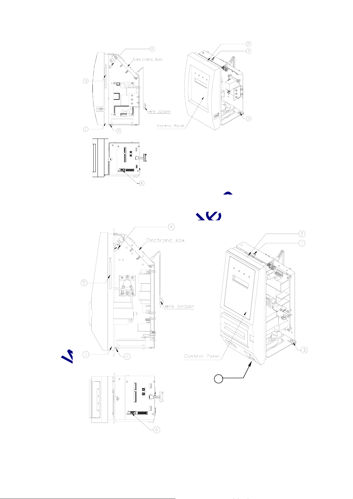
9.6 Replacing the electronics board (control panel)
Caution!
Make sure that the power cord is disconnected!
If the electronic box was damaged by any liquid that entered the box, do
not attempt to replace it. In this case only the factory technicians may
repair the autoclave.
Allow the autoclave to cool before removing outer covers.
1. Remove the autoclave cover (see para. 9.2 “Dismantling the Outer
Covers of the Autoclave”).
2. Remove the two screws that connected the plastic panel with the
digital electronic board to the autoclave (2).
3. Disconnect the flat cable from JP1-DIG-T2 to JP1 ANL-T2 (4).
4. Disconnect the flat cable of communicator from P1-ANL-T2 (6).
5. Disconnect the grounding cable shoe (5).
6. On autoclave models 2340 and 2540 disconnect the main switch.
7. Remove the plastic panel, including the electronics board (control
panel), from the autoclave.
8. Disconnect the control panel from the plastic panel and replace it
with a new one.
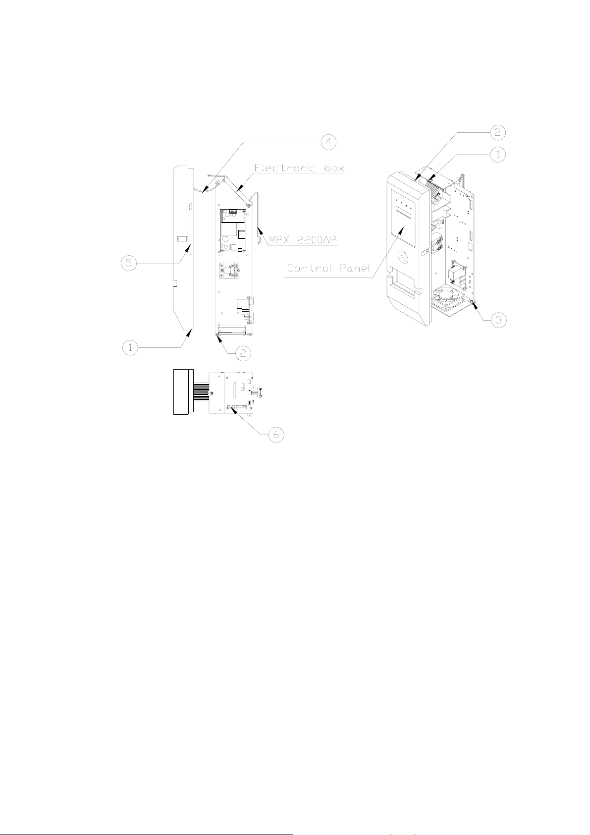
9.7 Replacing the Electronics Box
Caution!
Make sure that the power cord is disconnected!
If the electronic box was damaged by any liquid that entered the box, do
not attempt to replace it. In this case only the factory technicians may
repair the autoclave.
Allow the autoclave to cool before removing outer covers.
1. Remove the autoclave cover (see para. 9.2 “Dismantling the Outer
Covers of the Autoclave”).
2. Remove two screws from the bottom side and from the top (1, 3).
3. Disconnect all the electric system connectors from the electronics
base (including the MPX connectors).
4. Remove electronics box and replace with new one.
5. Re-assemble the instrument. Verify that the grounding connections
are connected correctly.
6. Test any cycle and verify that the autoclave operates as required.
26
www.shanghaidelan.com
Electronic box: 1730
7
Electronic box: 2340/2540
27
www.shanghaidelan.com
Electronic box: 3140/3850/3870
28
 Loading...