

Tuttnauer 2540 EHS, 3870 EHS Operation & Maintenance Manual
OPERATION
&
MAINTENANCE
MANUAL
Electronic Table-Top Pre and Post Vacuum
Autoclave
models 2540, 3870 EHS
Cat. No. MAN205-0034005EN Rev. D
Tuttnauer USA Co., Ltd., 25 Power Drive Hauppauge, NY 11788, USA, : (800) 624 5836, (631) 737 4850, Fax: (631) 737 0720
e-mail: info@tuttnauerUSA.com


1
TABLE OF CONTENT
DRAWINGS PAGE NO.
1 GENERAL
...........................................................................................................
4
1.1 Incoming Inspection
.................................................................................
4
1.2 Warranty
....................................................................................................
4
1.3 Warranty Statement
..................................................................................
4
2 GENERAL INFORMATION
..............................................................................
6
2.1 Introduction
...............................................................................................
6
2.2 Operating Conditions
................................................................................
8
2.3 Stand – by heating mode
...........................................................................
8
2.4 Utilities
.......................................................................................................
8
2.5 Overall Dimensions for the 2540 model
.................................................
11
2.6 Overall Dimensions for the 3870 model
.................................................
12
2.7 Technical Specifications
.........................................................................
13
2.8 Electrical Specifications
.........................................................................
13
2.9 Construction
............................................................................................
14
2.10 Water quality
...........................................................................................
14
2.11 Environment Emission Information
......................................................
15
2.12 Symbol Description
.................................................................................
15
2.13 Directives and Standards
........................................................................
16
3 STERILIZATION PROGRAMS
.......................................................................
19
3.1 Program 1 - Unwrapped Instruments (1 - Flash 273)
...........................
19
3.2 Program 2 (2 - WDry 273)
......................................................................
20
3.3 Program 3 (3-WDry 250)
........................................................................
21
3.4 Program 4
................................................................................................
22
3.5 Program 5 (5 - B&D Test)
......................................................................
24
3.6 Program 6 (6 – Vacuum Leakage Test)
.................................................
25
4 KEYBOARD (keys and display)
........................................................................
26
4.1 Description and Functions of the Front Panel Keyboard
.....................
27
4.2 Description of the Operational Messages
..............................................
30
4.3 Description of Displayed Error Messages and Safety Measures
..........
32
5 PRINTER
...........................................................................................................
34
5.1 Printer Operation
....................................................................................
34
5.2 DPU 20 Printer Handling
.......................................................................
36
5.3 DPU 30 Printer Handling
.......................................................................
37
6 PREPARATION BEFORE STERILIZATION
................................................
38
7 DENTAL HANDPIECE STERILIZATION
....................................................
41
8 OPERATION
.....................................................................................................
43
8.1 Operating Instructions
............................................................................
43
8.2 Lifting and carrying
................................................................................
44
8.3 Loading and unloading the Device
.........................................................
44
2
TABLE OF CONTENT (Cont.)
DRAWINGS PAGE NO.
9 MAINTENANCE INSTRUCTIONS
................................................................
46
9.1 Preventive and Scheduled Maintenance
................................................
46
9.2 Draining the Reservoir
............................................................................
47
9.3 Replacing the Air Filter
..........................................................................
48
9.4 Replacing the Door Gasket
.....................................................................
49
9.5 Replacing the Cartridge Fuse
.................................................................
50
9.6 Checking the Safety Valve
......................................................................
51
9.7 Cleaning water outlet strainer
................................................................
52
10 TROUBLESHOOTING FOR THE OPERATOR
............................................
53
11 SPARE PARTS LIST
........................................................................................
56
12 ACCESSORIES
.................................................................................................
56

3
TABLE OF CONTENT (Cont.)
DRAWINGS PAGE NO.
Suggested Site Drain Drawing
......................................................................................
10
Front View
.....................................................................................................................
17
Rear View
.......................................................................................................................
18
Front Panel Keyboard
...................................................................................................
26
4
1 GENERAL
Read the Operating Instructions carefully, before beginning any operation on the
autoclave!
1.1 Incoming Inspection
Upon receiving your Tuttnauer Autoclave carefully inspect the outside
of the shipping carton for signs of damage. If any damage to the carton
is found note the location with respect to the autoclave and check that
area of the autoclave carefully once it is fully unpacked. Observe
packing method and retain packing materials until the unit has been
inspected. Mechanical inspection involves checking for signs of
physical damage such as: scratched panel surfaces, broken knobs, etc.
If any damage is found contact your dealer as soon as possible so that
they can file a claim with the shipping carrier and also notify Tuttnauer.
All Tuttnauer products are carefully inspected prior to shipment and all
reasonable precautions are taken in preparing them for shipment to
assure safe arrival at their destination.
Note: Lifting and carrying should always be done by two people.
1.2 Warranty
We certify that this instrument is guaranteed to be free from defects in
material and workmanship for one year against faulty components and
assembly.
This warranty does not include routine cleaning and preventive
maintenance to be performed according to instructions in section 9.1
(Preventive and Scheduled Maintenance).
Tuttnauer warrantees all new EHS autoclaves for a period of one full
year, covering both parts and labor. This one-year warranty covers
defects in materials and workmanship on every part in the autoclave.
This warranty does not apply to any instrument that has been subjected
to misuse, neglect, accident or improper installation or application, nor
shall it extend to autoclaves that have been repaired or altered outside
the factory without prior authorization from Tuttnauer.
Tuttnauer’s obligation is limited to the repair or replacement of parts for
the autoclave. This warranty will be void if the unit is not purchased
from an authorized Tuttnauer dealer. No other warranties or obligations
are expressed or implied.
The Autoclave should only be used in a manner described in this
manual!
1.3 Warranty Statement
To activate the warranty, the registration card must be completed and
returned to Tuttnauer within fourteen (14) days of purchase or you may
call our customer service department at the number listed below.
For service on this product contact your dealer or Tuttnauer USA Co.
No product will be received or accepted for repair without prior return
authorization from Tuttnauer. All transportation charges to and from
Tuttnauer must be paid by the owner of the autoclave. During the first
90 days after purchase of an autoclave, Tuttnauer will pay shipping
costs on an individually evaluated basis and ONLY with pre-approval.

5
Note:
If you have any questions or there are any difficulties with this
instrument and the solution is not covered in this manual, please contact
your dealer or Tuttnauer USA Co. Do not attempt to service this
instrument yourself.
Tuttnauer USA Co. 25 Power Drive Hauppauge, NY, 11788, USA
: (800) 624 5836, (631) 737 4850, Fax: (631) 737 0720
e-mail:info@tuttnauer.com
6
2 GENERAL INFORMATION
2.1 Introduction
The EHS is a high speed, high vacuum, high capacity, hospital grade
sterilizer with FDA cleared flash cycle. A built in vacuum pump and
steam generator allows for increased load size and dramatically reduces
total cycle time. The closed door drying system provides a faster and
more thorough drying cycle. Six automatic cycles are available. Four
sterilization cycles and two test cycles. EHS models are available in a
10” or 15” chamber.
The EHS autoclave, models 2540 and 3870 are designed for the
sterilization of wrapped and unwrapped instruments and related items
found in dental, medical and veterinary clinics, first aid rooms,
hospitals, laboratories etc. They are electrically – heated pre and post
vacuum sterilizers, using steam as the sterilizing agent. A computerized
control unit ensures a fully automatic sterilization cycle, and the control
and monitoring of physical parameters.
The EHS pre / post vacuum sterilizer has the following features:
¾ It is a Class B sterilizer in accordance with the European standard
prEN 13060-2
¾ It has a pre-vacuum conditioning stage
¾ It has a post-vacuum drying phase.
¾ It has a jacketed chamber
¾ It has a dual compartment water reservoir
¾ It has a complete water discharge system
¾ It has a PC friendly communication system
The advantages of this pre / post vacuum sterilizer are:
¾ Dramatically faster overall cycle time
¾ Better and deeper steam penetration into loads
¾ Increased load size
¾ More thorough and efficient drying of materials
¾ Automatically maintained water reservoirs
¾ Immediate availability of steam for sterilization
¾ Non recycled water reduces maintenance
The Vacuum pump:
The pre and post vacuum stages are achieved with the use of a high
volume liquid ring vacuum pump.
The advantage of the pre-vacuum stage is felt during the sterilization
stage. Vacuum removal of at least 99.5% of the air in the chamber
allows the steam to penetrate deeper into packed materials. Deeper
penetration allows for larger loads to be sterilized, thus saving time by
having to run fewer cycles.
The advantage of the post-vacuum stage is an efficient and thorough
drying of bagged and wrapped items. This is accomplished by the
combined use of a heated chamber and the vacuum removal of residual
moisture.
7
The Jacketed chamber:
This autoclave has a jacketed stainless steel chamber. The space
between the walls of the chamber and jacket is used to generate and
provide the steam required by the autoclave. The heating elements are
located inside this cavity as is the mineral free water supplied by the
reservoir. Steam is produced and maintained here as long as the unit is
turned on, thereby eliminating waiting time and making possible steam
on demand.
This autoclave’s reservoir is divided into two compartments:
The front compartment is for supplying the steam generator with
mineral free water. It is replenished from a mineral free water source
and is maintained automatically by high and low sensors and a computer
controlled solenoid valve.
The rear compartment is for supplying the liquid ring vacuum pump
with tap water. It is replenished from a tap water source and is
maintained automatically by high and low sensors and a computer
controlled solenoid valve.
Printer option:
This autoclave can be equipped with an optional printer that prints the
preset and actual parameters of each cycle (temperature, pressure and
vacuum with respect to time).
Computer interface:
An outstanding feature of this autoclave is the communication system.
This system allows interfacing with a personal computer for control and
monitoring of the autoclave by means of a special software program.
This communication system also enables the transmission of data from
the autoclave through a modem - to a remote center for data logging or
subsequent processing.
This manual is intended for the user. It gives the user a general
understanding of the instrument and the best ways to operate and take
care of it, in order to obtain optimum effective results.
After reading this manual, operating and maintaining the autoclave will
be simple and easy. However since this instrument is built with high
technology sensitive components, no attempt should be made by the
user or any other unauthorized person to repair or recalibrate it.
Only technical personnel having proper qualifications and holding
technical documentation (including a technician manual) and adequate
information are authorized to service the apparatus.
8
2.2 Operating Conditions
This device is for indoor use only!
The sterilizer should be loaded only with autoclavable material!
The environment shall not exceed an ambient temperature of 104ºF
(40ºC) and a relative humidity of 85% respectively.
For optimal results from the first sterilization cycle, it is recommended to
perform a B & D cycle (cycle # 5) at the beginning of each working day.
2.3 Stand – by heating mode
While the autoclave is in the jacket heating stage, “St.By” is displayed in
the upper right corner of the LCD screen. This announcement is
maintained until the jacket reaches its working pressure, at which time
the message will change to “READY”. When the unit is first turned on it
will take approximately 10 - 20 minutes for the jacket to reach its
working pressure and temperature.
2.4 Utilities
For proper operation, these are the required utilities that need to be
supplied:
Site requirements for installation of a 2540 EHS
1. Counter top
able to support a minimum 200 lb. * (the unit is shipped
with a suitable stand - 26”W x 33”D x 34”H)
2. Counter space
minimum 20”W x 32”D x 20”H * (see unit dimensions
below)
3. City water
supply 15 – 58 psi with shut off valve having ½” NPT male
end. Higher rates of pressure will require the installation of a pressure
reducer (58 psi max) The minimum flow rate required is 0.66 gal/min.
(2.5 lit./min.). Installation of the valve should be 2” above counter height
at the rear of the unit.
4. Mineral Free water
supply 7 – 30 psi with shut off valve and ½” NPT
male end. If the water pressure, at the autoclave inlet, is higher then 58
psi (4 bar), adjust the shut off valve for a low water flow into the mineral
free water reservoir. The minimum rate of flow is 0.26 gal/min (1
lit/min). Installation of the valve should be 2” above counter height at the
rear of the unit.
* (an optional R.O. water system is available).
5. Electrical power
20A – 208V single phase. Connection required; flush
mount receptacle 6-20R, within 1 foot of the rear of the unit.
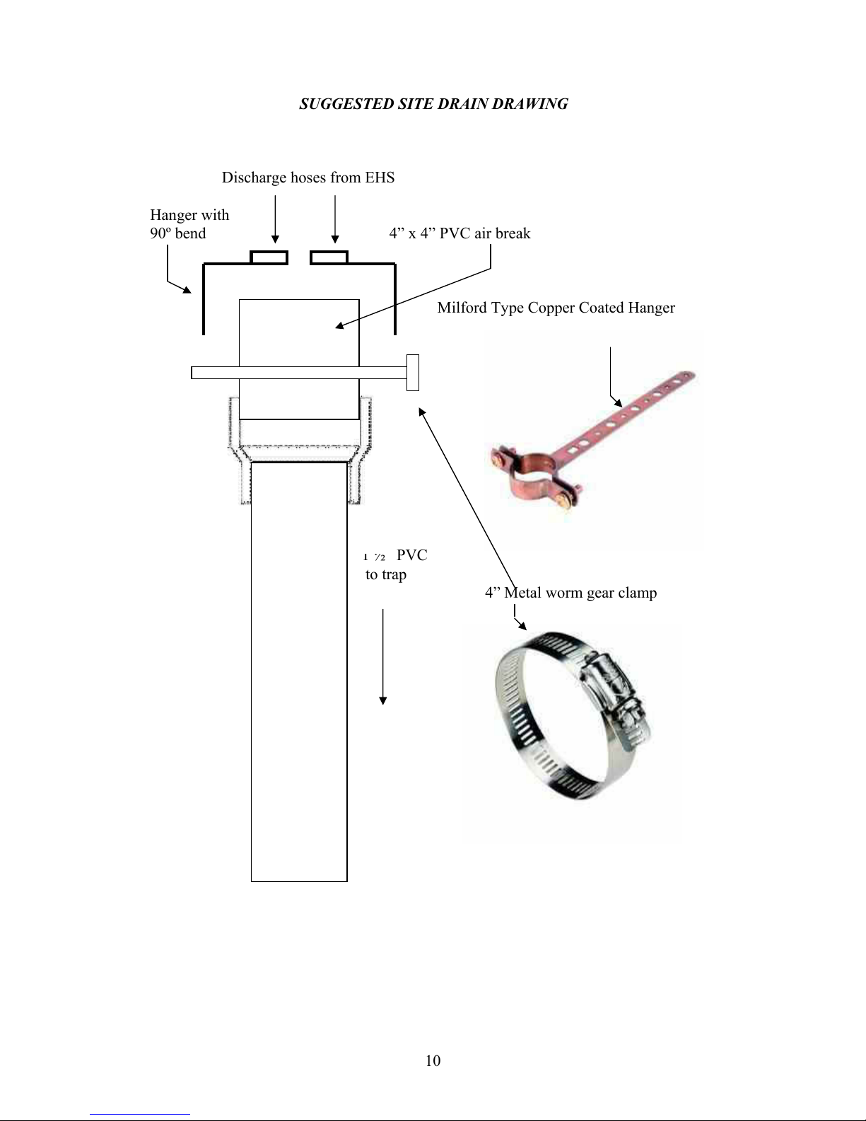
6. Drainage
should be to a 4” high 4” diameter air break, reducing down to
a 1 ½” vented line with a trap. All drainage components must be able to
withstand a non-continuous temperature of 140°F (60°C). Drain opening
should be within 1 foot of the rear of the unit and no higher than 16”
above the floor. The use of two ½”x 6" Milford Type Copper Coated
Hangers is required for the positioning of the two drain hoses over the
center of the air break and a 4” metal worm gear clamp to secure the
hangers. The hangers will need to be bent at a 90º angle to allow for
proper positioning and securing with the clamp.
* (see attached drawing)
9
Site requirements for installation of a 3870 EHS
1. Counter top
able to support a minimum 400 lb. * (the unit is shipped
with a suitable stand - 26”W x 33”D x 34”H)
2. Counter space
minimum 26”W x 39”D x 24”H * (see unit dimensions
below)
3. City water
supply 15 – 58 psi with shut off valve having ½” NPT male
end. Higher rates of pressure will require the installation of a pressure
reducer (58 psi max) The minimum flow rate required is 0.66 gal/min.
(2.5 lit./min.). Installation of the valve should be 2” above counter
height at the rear of the unit.
4. Mineral Free water
supply 7 – 30 psi with shut off valve and ½” NPT
male end. If the water pressure, at the autoclave inlet, is higher then 58
psi (4 bar), adjust the shut off valve for a low water flow into the
mineral free water reservoir. The minimum rate of flow is 0.26 gal/min
(1 lit/min). Installation of the valve should be 2” above counter height at
the rear of the unit. * (an optional R.O. water system is available)
5. Electrical power
20A - 208V three phase, three power lines plus a
ground. Connection required; flush mount receptacle or drop line with
NEMA # L1520R, this is a twist lock connector, within 1 foot of the rear
of the unit.
6. Drainage
should be to a 4” high 4” diameter air break, reducing down
to a 1 ½” vented line with a trap. All drainage components must be able
to withstand a non-continuous temperature of 140°F (60°C). Drain
opening should be within 1 foot of the rear of the unit and no higher
than 16” above the floor. The use of two ½”x 6" Milford Type Copper
Coated Hangers is required for the positioning of the two drain hoses
over the center of the air break and a 4” metal worm gear clamp to
secure the hangers. The hangers will need to be bent at a 90º angle to
allow for proper positioning and securing with the clamp.
* (see
attached drawing)
Caution!
Wastewater should be brought into the public sewage network in
accordance with the local rules or requirement i.e. only non-
hazardous liquids shall be disposed in public sewage!
10
SUGGESTED SITE DRAIN DRAWING
Discharge hoses from EHS
Hanger with
90º bend 4” x 4” PVC air break
Milford Type Copper Coated Hanger
1 ½” PVC
to trap
4” Metal worm gear clamp
11
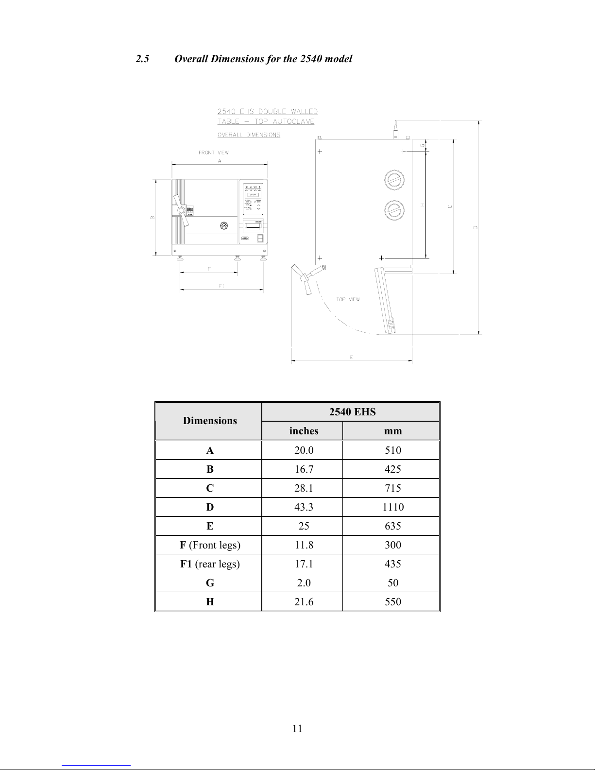
2.5 Overall Dimensions for the 2540 model
2540 EHS
Dimensions
inches mm
A
20.0 510
B
16.7 425
C
28.1 715
D
43.3 1110
E
25 635
F (Front legs)
11.8 300
F1 (rear legs)
17.1 435
G
2.0 50
H
21.6 550
12
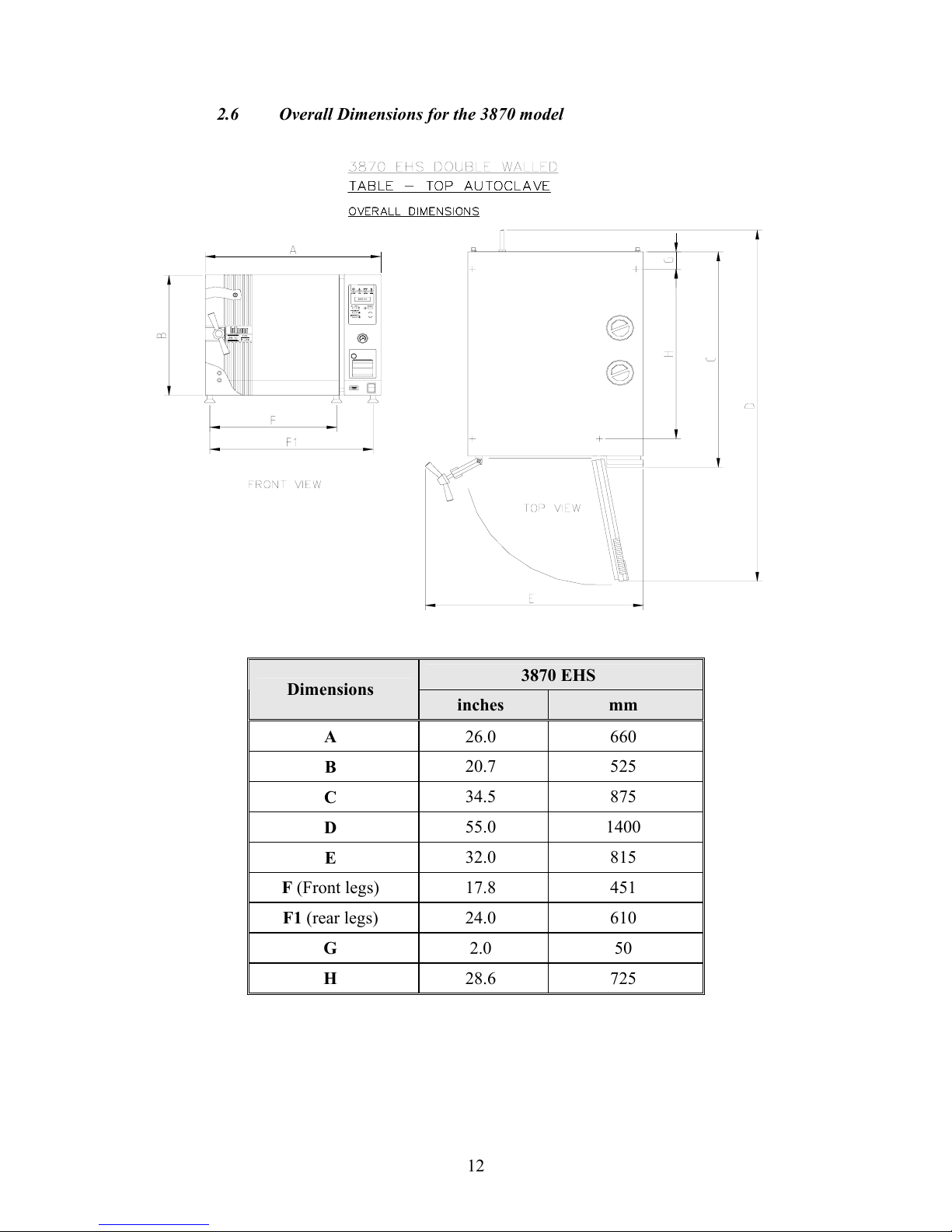
2.6 Overall Dimensions for the 3870 model
3870 EHS
Dimensions
inches mm
A
26.0 660
B
20.7 525
C
34.5 875
D
55.0 1400
E
32.0 815
F (Front legs)
17.8 451
F1 (rear legs)
24.0 610
G
2.0 50
H
28.6 725
13
2.7 Technical Specifications
Value
Property
2540 3870
Dia. 10” (254 mm) 15” (380 mm)
Chamber
Depth 18.7” (475 mm) 30” (760mm)
Chamber volume 6.1 gal (23 lit.) 22.2 gal (84 lit.)
Jacket volume 2.3 gal (8.5 lit.) 4.0 gal (15 lit.)
Shipping weight 165 lb (75 kg) 313 lb (142 kg)
Shipping volume 21.5 ft3 (0.6 m3)
27.2 ft
3
(0.77
m
3
)
Vacuum
pump
0.7 gal (2.5 lit.) 0.7 gal (2.5 lit.)
Reservoir
volume (upper
float switch)
Jacket 0.7 gal (2.5 lit.) 0.7 gal (2.5 lit.)
Max. Allowable Working
pressure (MAWP)
40 psi (2.76 bar) 40 psi (2.76 bar)
W
14” (35 cm)
H
1” (2.5 cm)
H
Big
2
6” (67 cm)
W 6.7” (17 cm) 11” (28 cm)
H 0.8” (2 cm) 1” (2.5 cm)
Tray dimensions
(Internal)
L 16.3” (41.5 cm)
Small
2
6” (67 cm)
No. of trays
2 2
IMS cassettes (optional)
3 full & 3 half 15 full
Load No. counter Counting from 0 to 9999 and nullifies.
2.8 Electrical Specifications
Value
Property
2540 3870
Heaters Power 3000W 6000W
Total Power 3200W 6200W
Voltage (VAC)
2ph +ground
208 VAC 50/60 Hz
3ph +ground
208 VAC 50/60 Hz
Amperage (A) 15 15
Frequency (Hz) 50/60 50/60
Protection against
electrical shock
Class I (IEC 60601-1)
14
2.9 Construction
The main parts of the autoclave are made of materials as indicated
below:
♦ Chamber is built of stainless steel 316 L.
♦ Door is made of stainless steel 304.
♦ Trays are made of stainless steel 304.
♦ Water reservoir is made of hard plastic material.
♦ Door handle is made of hard plastic material, which is safe to touch
and thermo-insulated.
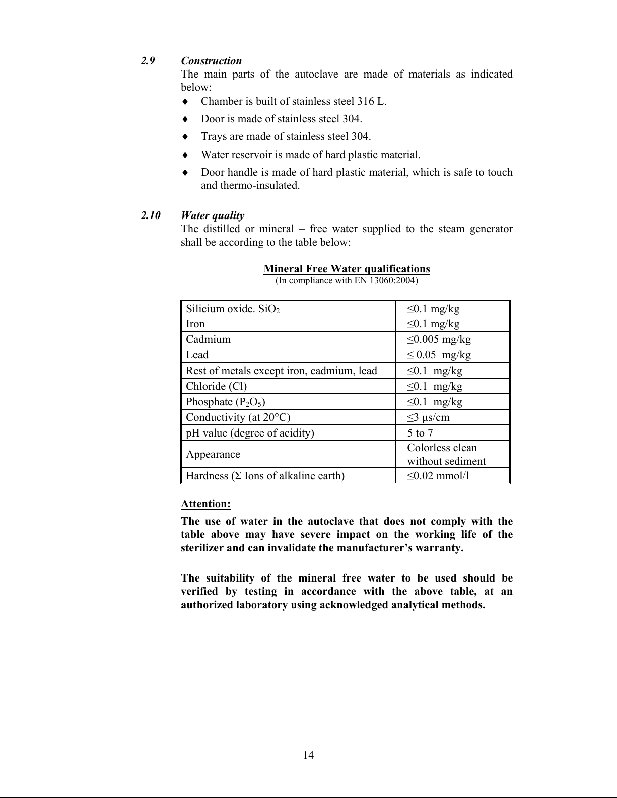
2.10 Water quality
The distilled or mineral – free water supplied to the steam generator
shall be according to the table below:
Mineral Free Water qualifications
(In compliance with EN 13060:2004)
Silicium oxide. SiO
2
≤0.1 mg/kg
Iron ≤0.1 mg/kg
Cadmium ≤0.005 mg/kg
Lead ≤ 0.05 mg/kg
Rest of metals except iron, cadmium, lead ≤0.1 mg/kg
Chloride (Cl) ≤0.1 mg/kg
Phosphate (P2O5) ≤0.1 mg/kg
Conductivity (at 20°C) ≤3 µs/cm
pH value (degree of acidity) 5 to 7
Appearance
Colorless clean
without sediment
Hardness (Σ Ions of alkaline earth) ≤0.02 mmol/l
Attention:
The use of water in the autoclave that does not comply with the
table above may have severe impact on the working life of the
sterilizer and can invalidate the manufacturer’s warranty.
The suitability of the mineral free water to be used should be
verified by testing in accordance with the above table, at an
authorized laboratory using acknowledged analytical methods.

15
2.10.1 Water for the vacuum system and the Drain Cooling
The feed water supplied to the liquid ring vacuum pump must
meet the following requirements:
♦ Hardness: 0.7 - 2 mmol/l.
♦ Water temperature: shall not exceed 59°F (15°C).
Note:
The use of hard water in the vacuum pump may invalidate the
warranty for the vacuum pump, since it can cause blocking of
the rotor, which can damage the pump.
2.11 Environment Emission Information
A. The peak sound level generated by the sterilizer is < 70 / dBA with
background noise of 60 dB.
B. The total heat transmitted by the sterilizer is:
< 100 W / h (341 btu) for 2540 EHS
< 150 W / h (512 btu) for 3870 EHS.
2.12 Symbol Description
Caution! Consult accompanying documents
Caution! Hot surface.
Caution! Hot steam.
Protective earth (Ground)
On-Off
16
2.13 Directives and Standards
Every autoclave meets the provisions of the following Directives and is
designed, manufactured and tested in compliance with the following
Standards:
2.13.1 Technical Directives
1. Medical device directive MDD/93/42/EEC.
2.13.2 Technical Standards
1. A.S.M.E. Code section VIII division 1 for pressure
vessels.
2. UL3101-1 for Laboratory use Electrical Equipment.
3. UL/IEL/EN 61010-1 – Safety of electrical equipment
…General requirement.
4. UL/IEL/EN 61010-2-041 – Particular requirement for steam
autoclaves.
5. UL listed E206879
6. ANSI/AAMI ST-55 Table-Top Steam Sterilizer
2.13.3 Quality standards
The manufacturing meets the following quality standards:
1. EN ISO 9001:2000 Quality System
2. ISO 13485:2003 Quality systems – Medical devices
– Particular requirements for the
application of ISO 9001.
3. 21CFR820 GMP for Medical Devices
The manufacturer retains all supporting documentation.
Both models were tested in accordance with ANSI/AAMI ST-55.
 Loading...