

Page 1

OPERATION
&
MAINTENANCE
MANUAL
Laboratory Vertical Steam Sterilizers
models
2540, 3150, 3170, 3850, 3870, 5050, 5075
ELV
Standard Autoclave
ELVC
Including Fast Cooling System
ELVPRC
Including Preparation for Fast Cooling System
Cat. No. MAN205-0036000EN Rev AA
Tuttnauer Europe B.V., Hoeksteen 11 4815 PR P.O. Box 7191 4800 GD Breda, The Netherlands
Tel: 31 (0) 765423510, Fax: 31 (0) 765423540
Page 2

Page 1 of 58 Pages
TABLE OF CONTENTS
PARAGRAPH PAGE NO.
1 GENERAL......................................................................................................................4
1.1 Incoming Inspection...........................................................................................4
1.2 Warranty...............................................................................................................4
1.3 Warranty Statement ............................................................................................4
1.4 Ordering Information.........................................................................................5
2 SAFETY INSTRUCTIONS..........................................................................................6
3 TECHNICAL DATA.....................................................................................................8
3.1 Introduction..........................................................................................................8
3.2 Operating Conditions..........................................................................................9
3.3 Directives and Standards....................................................................................9
3.4 Environment Emission Information.................................................................9
3.5 Electrical Data:.................................................................................................10
3.6 Specifications....................................................................................................10
3.7 Loading Capacities...........................................................................................11
3.8 Utility..................................................................................................................11
3.9 Symbol Description ..........................................................................................12
3.10 Water Quality....................................................................................................17
3.11 Safety Features .................................................................................................18
3.12 Description of Operation.................................................................................19
4 STERILIZATION PROGRAMS..............................................................................20
4.1 Program 1 – Unwrapped Instruments (1 – Instruments)............................20
4.2 Program 2 (2- Instruments)............................................................................21
4.3 Program 3 (3 –Waste)......................................................................................22
4.4 Program 4 – (4 – Liquid).................................................................................23
4.5 Program 5 (5- Liquid)...................................................................................... 24
4.6 Program 6 (6-Liquid + Cool) – option on ELVC only.................................25
5 KEYBOARD (keys and display)...............................................................................26
5.1 Description and Functions of the Front Panel Keyboard ..........................27
5.2 Description of the Operational Messages .....................................................30
5.3 Displayed Error Messages and Safety Measures.........................................32
6 PRINTER ....................................................................................................................34
6.1 Printer Operation.............................................................................................34
6.2 DPU-20 Printer Handling ...............................................................................36
6.3 DPU 30 Printer Handling ...............................................................................37
7 PREPARATION BEFORE STERILIZATION......................................................38
7.1 Instruments .......................................................................................................38
7.2 Tubing................................................................................................................39
7.3 Liquids................................................................................................................39
7.4 Loading.............................................................................................................. 39
Page 3

Page 2 of 58 Pages
8 OPERATION ..............................................................................................................40
8.1 Operating Instructions.....................................................................................40
8.2 Moving the Autoclave......................................................................................41
8.3 Loading and Unloading the Device ...............................................................41
9 DOOR SAFETY SYSTEM ........................................................................................43
9.1 Solenoid locking device ................................................................................... 43
9.2 Door Safety System for models 5050, 5075...................................................43
9.3 Piston Lifting Device For 3850/3870/5050/5075 ELV ................................47
10 SERVICE AND MAINTENANCE..........................................................................48
10.1 Preventive Maintenance..................................................................................48
10.2 Replacing the Air Filter...................................................................................49
10.3 Replacing the Door Gasket ............................................................................. 50
10.4 Checking the Safety Valve...............................................................................50
10.5 Cleaning water outlet strainer........................................................................53
11 TROUBLESHOOTING.............................................................................................54
12 SPARE PARTS LIST.................................................................................................58
13 ACCESSORIES..........................................................................................................58
Page 4

Page 3 of 58 Pages
TABLE OF CONTENT (Cont.)
DRAWINGS PAGE NO.
Overall Dimensions 2540 ELV...........................................................................................13
Overall Dimensions Drawing for the 3150 / 3170 ELV..................................................14
Overall Dimensions Drawing for the 3850 / 3870 ELV..................................................15
Overall Dimensions Drawing for the 5050/ 5075 ELV...................................................16
Front Panel Keyboard.........................................................................................................26
Baskets and Containers.......................................................................................................56
Page 5

Page 4 of 58 Pages
1 GENERAL
1.1 Incoming Inspection
The autoclave should be unpacked and inspected for mechanical damage
upon receipt. Observe packing method and retain packing materials until
the unit has been inspected. Mechanical inspection involves checking for
signs of physical damage such as: scratched panel surfaces, broken knobs,
etc.
If damage is apparent, contact your dealer or point of purchase, so that
they may notify the manufacturer and file a claim with the appropriate
carrier.
All
Tuttnauer products are carefully inspected prior to shipment and all
reasonable precautions are taken in preparing them for shipment to assure
safe arrival at their destination.
1.2 Warranty
We certify that this instrument is guaranteed to be free from defects in
material and workmanship for one year against faulty components and
assembly with the exception of glassware, lamps and heaters.
The warranty does not include and does not replace routine treatment
and preventive maintenance to be performed according to instructions
in paragraph 10.1 (Preventive Maintenance).
Our obligation is limited to replacing the instrument or parts, after our
examination, if within one year after the date of shipment they prove to be
defective. This warranty does not apply to any instrument that has been
subjected to misuse, neglect, accident or improper installation or
application, nor shall it extend to products that have been repaired or
altered outside the factory without prior authorization from us.
The Autoclave should not be used in a manner not described in this
manual!
1.3 Warranty Statement
The warranty registration must be completed and returned to our service
departments; within fourteen (14) days of purchase or the warranty will be
void.
Our Technical Service Depts can be reached at:
Tuttnauer Europe b.v., Hoeksteen 11, 4815 PR Breda, Netherlands.
+31/76-5423510,
Fax: +31/76-5423540, E-mail: info@tuttnauer.nl
Rudolf Gunz & Co. PTY LTD:
Service Department, 26-34 Dunning Avenue, Ros, 2018, Sydney,
Australia.
Service Department, Locked bag 690, Beaconsfield, NSW 2014,
Australia.
+61-2-99356600 Fax: +61-2-99356650
Page 6

Page 5 of 58 Pages
Note:
If there is any difficulty with this instrument, and the solution is not
covered in this manual, contact our representative or us first. Do not
attempt to service this instrument yourself. Describe the difficulty as
clearly as possible so we may be able to diagnose the problem and provide
a prompt solution.
If the autoclave is equipped with a printer, send along a copy of the last
printout for our inspection. If replacement parts are needed, stipulate the
model and serial number of the machine.
No products will be accepted for repair without proper authorization from
us. All transportation charges must be paid both ways by the owner. This
warranty will be void if the unit is not purchased from an authorized full
service
Tuttnauer dealer.
1.4 Ordering Information
Several items must be specified when ordering the unit from the dealer.
Exact model number (depending on desired chamber size).
Please specify the supply voltage available, 230/380V; 1PH or 3PH.
Temperature scale: Specify Centigrade or Fahrenheit.
Pressure scale: Specify kPa or psi.
1.4.1 Options
Printer option
Hanging temperature control probe for use with liquids, to
be placed directly inside a sample solution.
Cooling option - specify cooling method: with or without
compressed air. Air is used to balance the chamber
pressure during the cooling stage.
1.4.2 Accessories
Basket accessories: A set of two baskets is available for the unit.
The baskets are made of stainless steel wire and have a handle.
The basket allows the operator to load a large quantity of
materials into the chamber.
The pressure scale, printer option and cooling method can be set
up at any time by a technician.
Stainless steel containers: A stainless steel container, for waste
products, is available. This container has vent holes on its upper
part
Page 7

Page 6 of 58 Pages
2 SAFETY INSTRUCTIONS
The autoclave has unique characteristics. Please read and understand the operation
instructions before first operation of the autoclave. The following issues may
require instructions guidance provided by the manufacturer: how to operate the
autoclave, the door safety mechanism, the dangers involved in circumventing
safety means, how to ensure that the door is closed, and how to select a correct
sterilization program.
Make sure that you know where the main power switch is, where the water cut-off
valve is and where the compressed air disconnection valves (if applicable) is
located.
Autoclave maintenance is crucial for the correct and efficient function of the
device. We enclose a log booklet that includes maintenance recommendations,
with every device.
The weekly spore test is part of the preventive maintenance plan, along with the
annual validation of the sterilization processes that ensures appropriate
temperature dispersion within the chamber.
Never use the autoclave to sterilize corrosive products, such as: acids, bases and
phenols, volatile compounds or solutions such ethanol, methanol or chloroform
nor radioactive substances.
1. Never start using a new autoclave before the safety, licensing and
authorization department has approved it for use.
2. All autoclave users must receive training in proper usage from an
experienced employee. Every new employee must undergo a training
period under an experienced employee.
3. A written procedure must be established for autoclave operation,
including: daily safety tests, seal inspection and door hinge inspection,
smooth action of the closing mechanism, chamber cleaning, prevention of
clogging and preservation from corrosion, what is permitted and what is
prohibited for sterilization and choosing a sterilization program.
4. Liquids may be sterilized only with the “liquids” program. The container
must be covered but not sealed. Sealed bottles may only be sterilized using
a special program. The bottle must be either Pyrex or a Borosilicate glass
bottle.
5. When sterilizing plastic materials, make sure that the item can withstand
sterilization temperature. Plastic that melts in the chamber is liable to
cause a great deal of damage.
6. Individual glass bottles may be placed within an appropriate container that
will be placed in a basket. Never place glass bottles on the floor of the
autoclave. Never fill more than 2/3 of the bottle volume.
7. On closing the autoclave's door, make sure it is properly locked before
activating.
8. Before withdrawing baskets, wear heat resistant gloves.
9. Before opening the door, verify that there is no pressure in the chamber
(chamber pressure gauge is located on the autoclave's front panel or door,
depends on model).
10. Open the door slowly to allow steam to escape and wait 5 minutes before
you remove the load. When sterilizing liquids, wait 10 minutes.
Page 8

Page 7 of 58 Pages
11. Once a month, ensure that the safety valves are functioning, and once
annually a certified tester must conduct pressure chamber safety tests.
12. Once annually, or more frequently, effective tests must be performed, i.e.,
calibration and validation.
13. Examine the condition of assemblies on a regular basis. Make sure there
are no leaks, breaks, blockages, whistles or strange noises.
14. It is required to conduct maintenance operations as instructed.
15. Immediately notify the person in charge of any deviation or risk for the
proper function of the device.
Page 9

Page 8 of 58 Pages
3 TECHNICAL DATA
3.1 Introduction
Models 2540, 3150, 3170, 3850, 3870, 5050 and 5075, 5090 ELV are
vertical sterilizers designed especially for sterilization of instruments,
liquids and other materials in hospital laboratories, medical laboratories,
research institutes, food laboratories and pharmaceutical facilities.
A special feature of this sterilizer is the fast cooling operation, provided as
an option for the liquids sterilization cycle.
The sterilizer is fully automatic with a choice of six programs, eliminating
any need for operator intervention during a cycle. The sixth program is an
optional program including a cooling stage (program 7 is for leakage test
only). A computerized control unit enables precise control and monitoring
of physical parameters and clear documentation of the sterilization cycles.
The autoclave is equipped with a safety valve, which blows off at an
overpressure of over 25 psi, which is located on the rear of the autoclave.
The control system provides adequate protection, to ensure the safety of
personnel and reliable operation with a minimum of down time.
On all models (except 1730), a printer is an optional addition to the
autoclave. The printer prints the preset and actual parameters of the cycle
(temperature, time and pressure/vacuum).
The autoclave is equipped with a pressure gauge designed for reference
only. In case that there is any problem with electricity supply during a
sterilization cycle the pressure gauge will be used to verify that there is
pressure in the chamber.
This manual provides information for the following models:
ELV – this is the basic model of the vertical laboratory autoclave.
ELVC – this model includes a cooling system that enables cycles with
fast cooling.
ELVPRC – this model includes only the cooling coil as a preparation
for a cooling system but performs as ELV. A Tuttnauer technician can
upgrade this model to ELVC.
This manual is intended to give the user a general understanding of how
the autoclave works and indicates best ways to operate and maintain it in
order to obtain optimum results and a trouble free operation.
After reading this manual, operating the autoclave should be straight
forward. However, since the autoclave is built using high technology
sensitive components, no attempt should be made by the user or any other
unauthorized person to repair or re-calibrate it.
Only technical personnel having proper qualifications, holding technical
documentation and adequate test instrumentation, are authorized to
undertake repair or service.
Page 10

Page 9 of 58 Pages
3.2 Operating Conditions
The autoclave is intended to work in ‘indoor’ conditions only.
Only autoclavable materials shall be used.
The ambient temperature shall not exceed 40ºC and a relative
humidity up to 85%.
The autoclave shall not be used in a manner not specified in this
manual!
Do not use the autoclave in the presence of dangerous gases.
The packed or unpacked device shall be stored in ‘indoor’ conditions.
Caution
Waste water should be brought into the public net in
accordance with the local rules or requirements i.e. only nonhazardous liquids shall be disposed in public sewage!
3.3 Directives and Standards
Every autoclave meets the provisions of the following Directives and is
constructed in compliance with the following Standards:
3.3.1 Technical Directives
1. Pressure Equipment Directive 97/23/EC.
2. Council Directive for voltage limits 73/23/EEC.
3. Electromagnetic Compatibility Requirements Directive
89/336/EC.
3.3.2 Technical Standards
1. ASME code (models 2540, 3150, 3850, 3870).
2. EN 13445 (models 5050, 5075).
3. IEC-61010-1 & IEC-61010-2-040 - Safety requirements for
medical device.
4. EN 61326 – EMC Requirements .
3.3.3 Quality standards
The manufacturing plant meets the following quality standards:
1. EN ISO 9001:2008– Quality System
2. ISO 13485:2003 – Quality systems – Medical devices.
3.4 Environment Emission Information
A. Peak sound level generated by the sterilizer is « 70 / dBA with a back
sound level of 60 dBA.
B. Total heat transmitted by the sterilizer is < 100 W/h
Page 11

Page 10 of 58 Pages
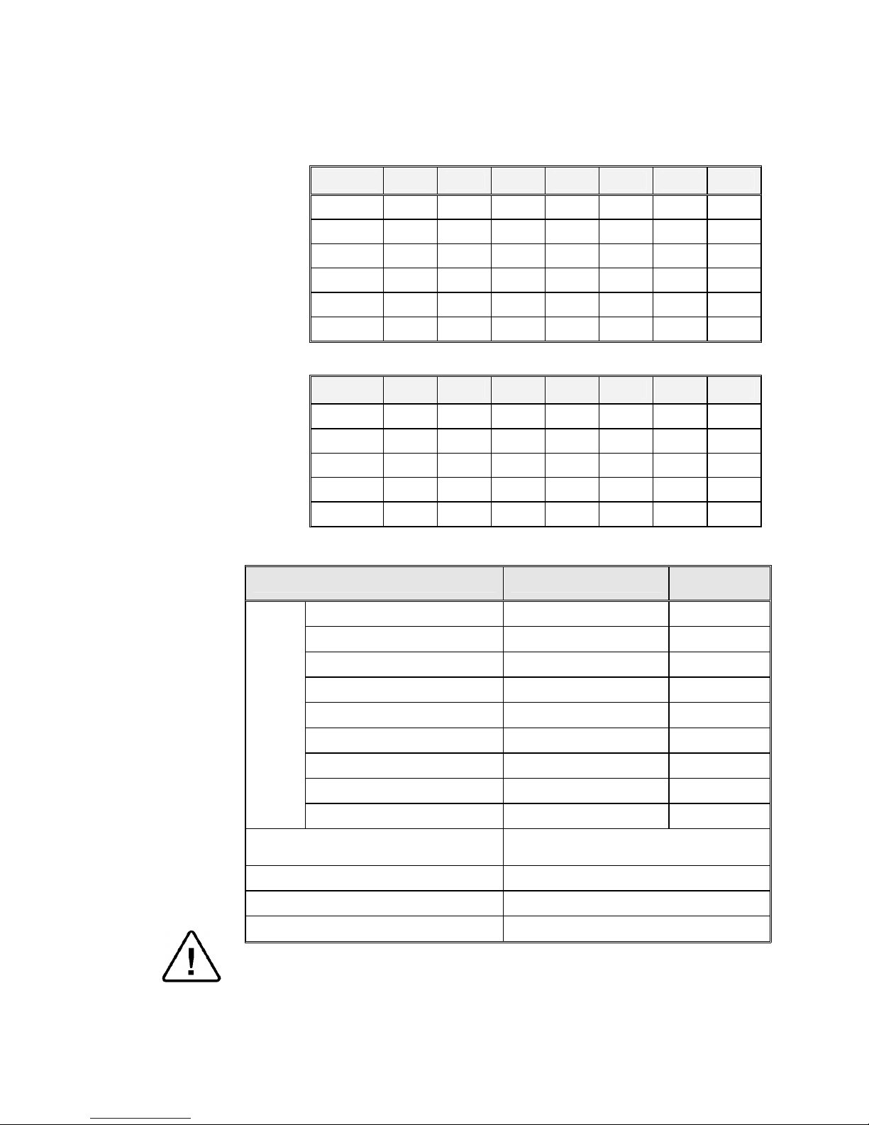
3.5 Electrical Data:
2540 3150 3170 3850 3870 5050 5075
Ampere (A) at 1Ph/230V/50/60 Hz
26 26 39 39
Ampere (A) at 3Ph/380V/50/60 Hz
8.7 8.7 13.0 13.0
Ampere (A) at 3Ph/230V/50/60 Hz
17 17 23 23
Ampere (A) at 3Ph/208V/50/60 Hz
17 17 23 23
Watts (W) 2400 3300 3300 6000 6000 9000 9000
Protection against electrical shock Class I
Models 3850/70, 5050/75 are equipped with a switching box for 1 or 2 h to 3Ph
3.6 Specifications
3.6.1 Dimensions
DIMENSIONS
MODEL
2540 3150 3170 3850 3870 5050 5075
Chamber diameter in mm. 250 310 310 380 380 500 500
Chamber depth in mm. 400 550 730 480 680 520 750
Chamber volume (lit.) 23 40 59 65 85 110 160
Overall
dimensions
Height (mm) 665 780 960 760 960 770 1000
Width (mm) 500 580 580 650 650 700 700
Length (mm.) 335 420 420 500 500 880 880
3.6.2 Technical Data
PROPERTY
MODEL
2540 3150 3170 3850 3870 5050 5075
Chamber material
St. St.
316 Ti
(1.4571)
St. St.
316 Ti
St. St.
316 Ti
St. St.
316 Ti
St. St.
316 Ti
St. St.
316 Ti
St. St.
316 Ti
Door material
ST.ST.
304L
ST.ST.
304L
ST.ST.
304L
ST.ST.
304L
ST.ST.
304L
St. St.
316 Ti
St. St.
316 Ti
Air supply pressure
to be regulated (Bar)
3-8 3-8 3-8 3-8 3-8 3-8 3-8
Feed water pressure
To be regulated (Bar)
2-3 2-3 2-3 2-3 2-3 2-3 2-3
Net weight (kg)
48 45 53 85 100 171 190
Shipping volume (m
3
)
0.21 0.56 0.56 0.56 0.56 1.35 1.35
Shipping weight (kg)
57 85 93 101 116 204 223
Chamber insulation
-
Fiber glass with reinforced material
Outer Cabinet - Stainless Steel
Page 12
Page 11 of 58 Pages
3.7 Loading Capacities
3.7.1 Erlenmeyer Flasks
SIZE 2540 3150 3170 3850 3870 5050 5075
250 ml 2 x 4 3 x 7 3 x 7 2 x 12 3 x 12 2 x 21 3 x 21
500 ml 1 x 2 2 x 4 3 x 4 2 x 8 3 x 8 2 x 14 3 x 14
1000 ml 1 2 x 2 3 x 2 1 x 5 2 x 5 2 x 8 3 x 8
2000 ml 1 1 2 x 1 1x2 2 x 2 1x5 2 x 5
3000 ml 1 1 2 x 1 1 2 x 1 1x4 2 x 4
5000 ml — 1 1 1 1 1x2 1x2
3.7.2 Medium Flasks (Schott)
SIZE 2540 3150 3170 3850 3870 5050 5075
250 ml. 2 x 7 3 x 11 3 x 11 2 x 19 3 x 19 2 x 32 3 x 32
500 ml 1 x 4 2 x 7 3 x 7 2 x 12 3 x 12 2 x 21 3 x 21
1000 ml 1x3 1 x 5 2 x 5 1 x 8 2 x 8 2 x 15 3 x 15
2000 ml 1 31x2 2 x 2 1x4 2 x 4 1x8 2 x 8
5000 ml 1 1 1 1 1 1x4 2 x 4
3.8 Utility
Utility Power
Recommended
Circuit Breaker
Power
Supply
2540
1Ph, 230V/50/60Hz 20A
3150/70
1 or 2 Ph, 230V/50/60Hz 25A
3850/70
3 Ph, 208V/50/60Hz 25A
3850/70
3 Ph, 230V/50/60Hz 25A
3850/70 with switching box
1 or 2 Ph, 230V/50/60Hz 30A
3850/70, 5050/75
3 Ph, 400V/50/60Hz 20A
5050/75
3 Ph, 208V/50/60Hz 30A
5050/75
3 Ph, 230V/50/60Hz 30A
5050/75 with switching box
45A
Compressed Air (ELVC models
only)
1/2" 3-4 Bar
Tap water
1/2", 2-3 Bar
Mineral free water
1/2", 2-4 Bar
Drain
Withstanding temp. of 80°C
Attention:
The electrical net must be protected with a current leakage safety relay.
The electrical network must comply with local rules or regulations.
Page 13

Page 12 of 58 Pages
3.9 Symbol Description
Caution! Consult accompanying documents
Caution! Hot surface.
Caution! Hot steam.
Protective earth (Ground)
On-Off
Page 14
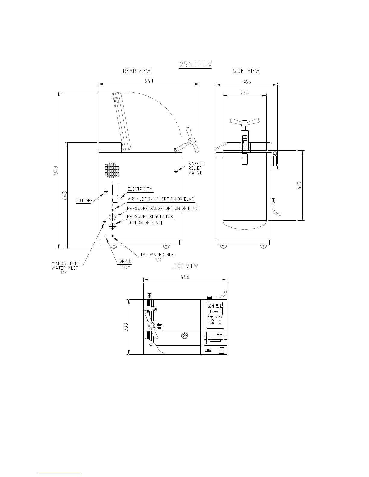
Page 13 of 58 Pages
OVERALL DIMENSIONS 2540 ELV
Page 15
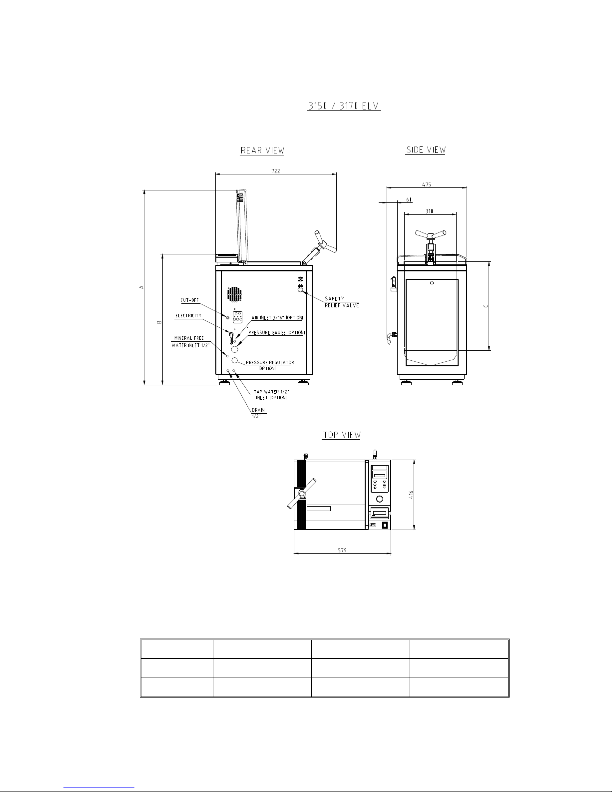
Page 14 of 58 Pages
OVERALL DIMENSIONS DRAWING FOR THE 3150 / 3170 ELV
Note:
The dimensions A, B and C are different for the models 3150 and 3170, as
indicated below
TYPE A B C
3150
1165 780 530
3170
1345 960 710
Page 16
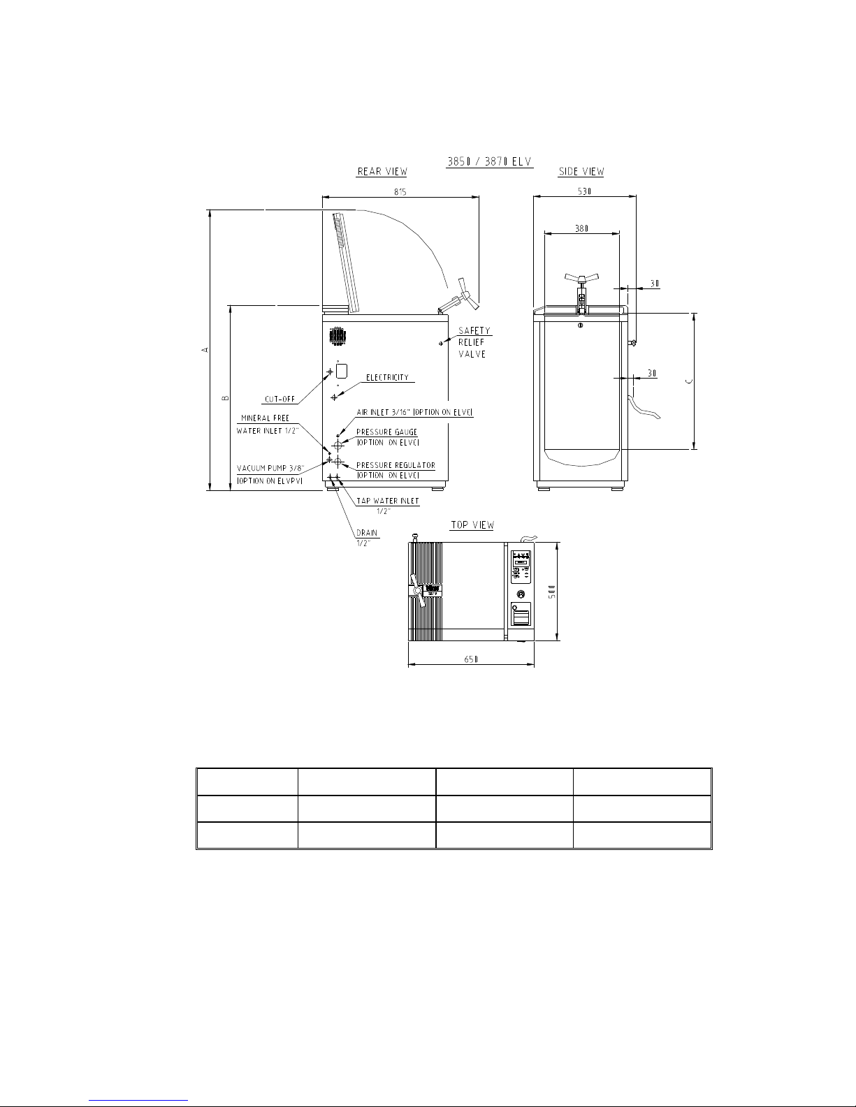
Page 15 of 58 Pages
OVERALL DIMENSIONS DRAWING FOR THE 3850 / 3870 ELV
Note:
The dimensions A, B and C are different for the models 3850 and 3870, as
indicated below
TYPE A B C
3850
1220 745 500
3870
1400 925 680
Page 17
Page 16 of 58 Pages
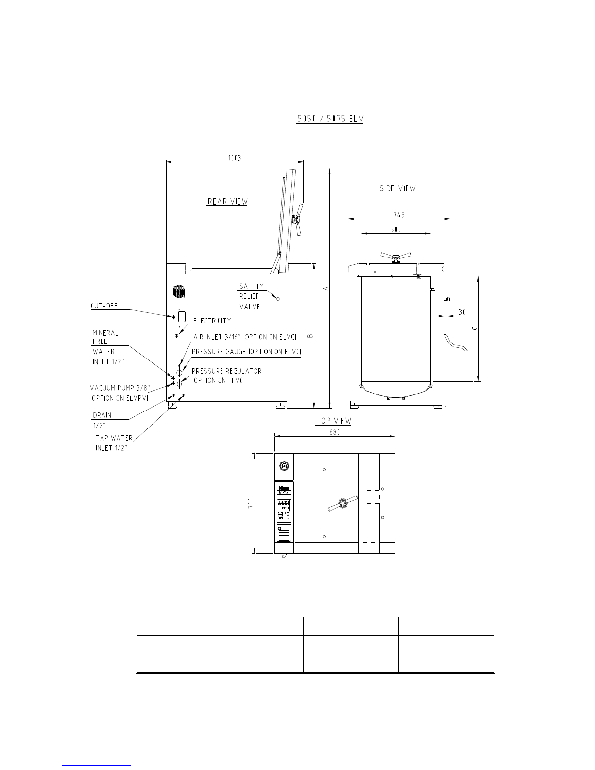
OVERALL DIMENSIONS DRAWING FOR THE 5050/ 5075 ELV
Note:
The dimensions A, B and C are different for the models 5050 and 5075, as
indicated below
TYPE A B C
5050
1440 780 503
5075
1670 1010 733
Page 18
Page 17 of 58 Pages
3.10 Water Quality
3.10.1 Water for Steam Generation
The distilled or mineral – free water supplied to the autoclave
should have the physical characteristics and maximum
acceptable level of contaminants indicated in the table below:
Physical Characteristics and Maximum acceptable
contaminants levels in steam for sterlizers
(According to EN 13060:2004).
Element
Condensate
–
allowable
content
Silicium oxide. SiO
2
≤0.1 mg/kg
Iron ≤0.1 mg/kg
Cadmium ≤0.005 mg/kg
Lead ≤ 0.05 mg/kg
Rest of metals except iron,
cadmium, lead
≤0.1 mg/kg
Chloride (Cl) ≤0.1 mg/kg
Phosphate (P2O5) ≤0.1 mg/kg
Conductivity (at 20°C) ≤3 μs/cm
pH value (degree of acidity) 5 to 7
Appearance
Colourless clean without
sediment
Hardness (Σ Ions of alkaline
earth)
≤0.02 mmol/l
Compliance with the above data should be tested in accordance
with acknowledged analytical methods, by an authorized
laboratory.
Attention:
We recommend testing the water quality once a
month. The use of water for autoclaves that does not comply
with the table above may have severe impact on the working
life of the sterilizer and can invalidate the manufacturer’s
guarantee.
3.10.2 Drain Cooling
The feed water supplied to the drain cooling must meet the
following requirements:
Hardness: 0.7 - 0.2 mmol/l.
Water temperature shall not exceed 15°C.
Page 19

Page 18 of 58 Pages
3.10.3 Reverse Osmosis
A Reverse Osmosis (RO) system may be used to improve the
quality of the water used to generate steam in the autoclave
chamber.
In RO, the water is forced through a semi-penetrable membrane,
which filters out contaminants to a high degree of efficiency. In
deionisation (DI) ions and charged particles are removed either
by electric fields or by ion exchange in resin beds.
Although the RO cannot normally attain the degree of purity
possible with the DI methods, it is more than adequate for the
feed water intended for clean-steam generators.
Moreover the RO has several advantages:
1. RO is cheaper to install and to run than DI.
2. RO removes particulate matter, organic molecules and
pyrogens that DI cannot remove
3. RO water is less corrosive to steel and copper than DI
water.
4. RO maintenance requirements are less demanding than
those of the DI units.
Therefore the use of mineral free water will contribute to better
performance and longer life of the autoclave.
3.11 Safety Features
This autoclave includes built-in safety features such as:
Error message display.
Temperature dependent door locking according to European standards.
Electronic pressure and temperature measurement.
Safety relief valve to avoid build-up of excessive pressure.
Door switch enabling operation to be started only when the door is
closed.
Water level safety device.
Excess temperature protection.
Page 20

Page 19 of 58 Pages
3.12 Description of Operation
3.12.1 Heat
The ELV vertical autoclaves are equipped with immersion type,
heating elements. After water has been introduced to the
chamber and the unit has been activated, the heating elements
begin to heat. The temperature and pressure in the chamber
increase until appropriate levels are reached. Sensors located
inside the chamber control the temperature and pressure levels.
3.12.2 Sterilization
The sterilization temperature is factory set at 134C (273F) for
instruments and at 121
C (250F) and 105C (221F) for liquids
and other materials for which this temperature is appropriate.
These settings may be modified before each cycle. When
sterilization temperature is reached, the timed sterilization cycle
begins.
3.12.3 Exhaust
When the timed sterilization cycle is complete, the unit enters
into the exhaust stage, provided that a program other than the
liquid program was selected. The steam is exhausted from the
chamber, bringing the internal pressure down to atmospheric
pressure.
3.12.4 Cooling
The autoclave is designed to operate two liquid cooling cycles,
as follows:
3.12.5 Sealed bottles (cooling with compressed air)
On completion of the sterilization stage, feed water starts
flowing through the cooling coil mounted around the outer side
of the chamber.
Compressed air is injected inside the chamber and keeps a
constant air pressure to balance the internal pressure of the
liquids inside the bottles. Compressed air is passed through a
0.2µ microbiological filter. When temperature of the liquids
reaches the final set temperature, the cooling stage is completed,
flowing water and compressed air is stopped, pressure in the
chamber goes down to atmospheric pressure.
At this stage, the door of the autoclave can be opened and the
sterilized materials can be taken out of the chamber.
3.12.6 Unsealed bottles (cooling without compressed air)
On completion of sterilization, steam is exhausted from the
chamber at a slow rate. When chamber pressure goes down to
atmospheric pressure, water starts flowing through the cooling
coil mounted around the outer side of the chamber. On
conclusion of the cycle the water flow is stopped automatically,
process is completed and it is possible to open the door and take
out the sterilized goods from the chamber.
Page 21

Page 20 of 58 Pages
4 STERILIZATION PROGRAMS
The autoclave offers 6 sterilization programs without drying +1 test program.
4.1 Program 1 – Unwrapped Instruments (1 – Instruments)
Program 1 is recommended for sterilizing unwrapped instruments and
materials for immediate use and preventing cross infection at temperature
134
ºC.
Nominal Parameters
Sterilization temperature: 134ºC (273ºF)
Sterilization time: 3 mins.
Operations Sequence
Heating phase; water enters the chamber and warms up until the
sterilization temperature is reached.
Fast exhaust phase (Ex. Mode=1); steam is rapidly exhausted from
the chamber, until pressure equalizes atmospheric pressure.
Note:
The sterility of instruments processed in unwrapped cycles cannot be
maintained if exposed to non-sterile environment.
TIME
PRESSURE (kPa)
TEMPERATURE
Ambient Pressure
and Temperature
t1 t2
t3
t1 = Heating stage
t2 = Sterilization stage
t3 = Drying Stage
= Temperature
= Pressure
Page 22

Page 21 of 58 Pages
4.2 Program 2 (2- Instruments)
Program 2 is recommended for sterilizing unwrapped instruments and
materials for immediate use and preventing cross infection at temperatures
of 121ºC.
Nominal parameters
Sterilization temperature: 121ºC (250ºF).
Sterilization time: 15 mins.
Operations Sequence
Heating phase; water enters the chamber and warms up until the
sterilization temperature is reached.
Sterilization phase; temperature is maintained constant at the
preset level for the sterilization time.
Fast exhaust phase (Ex Mode=1); steam is rapidly exhausted from
the chamber, until pressure equalizes atmospheric pressure.
Note:
The sterility of instruments processed in unwrapped cycles cannot
be maintained if exposed to non-sterile environment.
TIME
PRESSURE (kPa)
TEMPERATURE
Ambient Pressure
and Temperature
t1 t2
t3
t1 = Heating stage
t2 = Sterilization stage
t3 = Drying Stage
= Temperature
= Pressure
Page 23

Page 22 of 58 Pages
4.3 Program 3 (3 –Waste)
For waste materials when the manufacturer recommends autoclaving at a
temperature of 121ºC.
Nominal Parameters
Sterilization temp.: 121ºC (250ºF)
Sterilization time: 20 mins.
Operations Sequence
Heating phase; water enters the chamber and heats up until the
sterilization temperature is reached.
Sterilization phase; temperature is maintained constant at the
preset level for the sterilization time.
Slow exhaust (Ex. Mode =3); steam is slowly exhausted from the
chamber, until it reaches a temperature of 100ºC. At this point the
exhaust valve is opened.
The options available are described in paragraph 2. (Technical data).
TIME
PRESSURE (kPa)
TEMPERATURE
Ambient Pressure
and
Temperature
t1 t2 t3
t1 =
Heating
stage
t2 = Sterilization stage
t3 = Slow Exhaust Stage
= Pressure
= Temperature
1000C
Page 24

Page 23 of 58 Pages
4.4 Program 4 – (4 – Liquid)
For liquids when the manufacturer recommends autoclaving at
temperatures of 121ºC with no drying cycle.
Nominal Parameters
Sterilization temperature: 121ºC (250ºF).
Sterilization time: 20 mins.
Operations Sequence
Heating phase; The water enters the chamber and heats up until
the sterilization temperature is reached.
Sterilization phase; temperature is maintained constant at preset
level for the sterilization time.
Slow exhaust phase (Ex. Mode=4); steam is slowly exhausted
from the chamber, until it reaches the required temperature of
around 85ºC and the pressure equals the atmospheric pressure.
TIME
PRESSURE (kPa)
TEMPERATURE
Ambient Pressure
and Temperature
t1 t2 t3
t1 =
Heating
stage
t2 = Sterilization stage
t3 = Slow Exhaust S tage
= Pressure
= Temperature
Page 25

Page 24 of 58 Pages
4.5 Program 5 (5- Liquid)
For liquids when the manufacturer recommends autoclaving at
temperatures of 105ºC with no drying cycle.
Nominal Parameters
Temperature:105ºC (225ºF).
Time: 18 mins.
Operations Sequence
Heating phase; The water enters the chamber and heats up until
the sterilization temperature is reached.
Sterilization phase; temperature is maintained constant at the
preset level for the sterilization time.
Slow exhaust phase (Ex. Mode = 4); steam is slowly exhausted
from the chamber, until it reaches the required temperature of
approximately 85ºC and the pressure equals the atmospheric
pressure.
TIME
PRESSURE (kPa)
TEMPERATURE
Ambient Pressure
and Temperature
t1 t2 t3
t1 =
Heating
stage
t2 = Sterilization stage
t3 = Slow Exhaust Stage
= Pressure
= Temperature
Page 26

Page 25 of 58 Pages
4.6 Program 6 (6-Liquid + Cool) – option on ELVC only
For materials when the manufacturer recommends sterilization to
temperatures of 121ºC with no drying cycle.
Nominal Parameters
Sterilization temperature: 121ºC (250ºF).
Sterilization time: 30 mins.
Operations Sequence
Heating phase; the water enters the chamber and heats up until the
sterilization temperature is reached.
Sterilization phase; temperature is maintained constant at the
preset level for the sterilization time.
Forced cooling, to minimize the pressure difference between the
bottle with the liquid and chamber. This is done by supplying
compressed air into the chamber. The temperature decreases to
85°C and the pressure decreases until it is close to atmospheric
pressure. The forced cooling shortens the cooling stage
significantly.
Slow exhaust phase (Ex. Mode=6); until the pressure equals the
atmospheric pressure.
TIME
PRESSURE (kPa)
TEMPERATURE
Ambient Pressure
and Temperature
t1 t2
t3
t1 =
Heating
stage
t2 = Sterilization stage
t3 = Forced cooling Stage
t4 = Slow Exhaust S tage
= Pressure
= Temperature
Page 27

Page 26 of 58 Pages
5 KEYBOARD (keys and display)
Front Panel Keyboard
Page 28

Page 27 of 58 Pages
5.1 Description and Functions of the Front Panel Keyboard
The command panel is comprised of 3 sections:
On the lower section there are 6 keys; 3 command keys and 3
programming keys.
The middle section consists of the LCD display with two rows and 16
characters on each line.
The top section consists of 4 signal lights that indicate the status of the
autoclave.
1. Sel. Cycle (select cycle) key
This key enables selecting the desired program out of 6 programs.
Pressing this key advances the selected program to the next (e.g. from
program 2 to 3).
If the system is set to program 6, pressing the key returns to program
1.
This autoclave has the following available programs:
1. Unwrapped Instruments with fast exhaust without drying 134
ºC
(273
ºF)/ 3 minutes.
2. Unwrapped Instruments with fast exhaust without drying 121
ºC
(250
ºF) /15minutes.
3. Waste 121
ºC (250ºF)/20 minutes without drying.
4. Liquids 121
ºC (250ºF)/20 minutes without drying.
5. Liquids 105
ºC (221ºC)/18minutes with slow exhaust.
6. Special material 121ºC (250ºC)/30 minutes with cooling and slow
exhaust (on model ELVC only)
2. Parameters key
This key displays for 3 seconds the three parameters of the program.
After selecting the program, it is possible to have the parameters
displayed by pressing this key; the top line reads the following data:
Sterilization Temp
St
erilization Time
Dry Time
134ºC
S = 3m.
D=Ø
The data is erased automatically after 3 seconds, or if the parameter
key is pressed again during these three seconds.
Page 29

Page 28 of 58 Pages
3. Start/ Stop key
This key commands the following 3 functions:
Starting the process.
Stopping the process.
Canceling the FAIL message from the command panel and
opening the electric door locking if available.
Note:
This key cannot be used during the EXE stage/
Starting the process:
It is active while the autoclave is in standby position, if the door
is closed and water level in the reservoir is normal, pressing this
key starts the selected process.
Stopping the process:
It is active while the autoclave is in process, pressing this key at
any stage of the process stops operation.
Canceling the FAIL message
The end of an aborted process, the FAIL light is turned on and
an error message is displayed on the screen indicating the cause
of the failure.
Pressing this key cancels the displayed message and switches off
the FAIL light.
4. Program key
This key is designed for programming the clock and setting different
parameters by the service technician by means of the UP (5) DOWN
(6) keys.
When the PROGRAM key is pressed, the date is displayed with the
cursor under the day. Pressing the PROGRAM key again moves the
cursor under the month and then on to the year.
After pressing the PROGRAM key again the time of the day will be
displayed with the cursor under the hour. Pressing the PROGRAM
key again moves the cursor to the minutes parameter. Each time the
UP/DN key is pressed, the value of the parameter above the cursor is
changed.
After the date and time parameters are set, pressing the PROGRAM
key shows CODE: 000.
A code known to the technical personnel will be set to change certain
parameters and perform a digital calibration of the system, as
described in detail in the technician section.
Page 30

Page 29 of 58 Pages
5. UP key
This key enables increasing the value displayed above the cursor, at
the clock programming and for setting of certain parameters by the
technician.
6. DN key
This key enables decreasing the value displayed above the cursor, at
the clock programming and for setting of certain parameters by the
technician.
7. START LED indicator
When the “START” LED indicator is on it; indicates that the system
is running a program.
8. FAIL LED indicator
When the “FAIL” LED indicator is on; it indicates that the cycle has
failed
either as a result of exceeding the allowable limits or the STOP
key has been pressed.
9. WATER LED indicator
When the “WATER” LED indicator is on; it indicates that there is no
water in the chamber.
10. DOOR LED indicator
If the “Start” key is pressed and the door is unlocked the light will
signal
twice and the buzzer will sound four times.
If a cycle is in progress and fails on door unlocked “FAIL” LED
indicator
will lit and a message “Door Unlock” will be displayed.
Page 31

Page 30 of 58 Pages
5.2 Description of the Operational Messages
The display is comprised of 2 rows, each row has 16 characters.
5.2.1 The upper row:
On the right side of the upper row, 6 characters are allotted for
displaying the stage in progress
ST. BY - not in operation.
WATER - water inlet stage.
HEAT - heating stage.
STER - sterilization stage.
EXH - exhaust stage
COOL – forced cooling (if applicable)
On the left side of the upper row, 10 characters are allotted for
the selected programs.
1-Instruments (FAST 134) - fast exhaust
2- Instruments (FAST 121) - fast exhaust
3-Waste (Waste 121) - slow exhaust
4-Liquids (liquids 121) - slow exhaust.
5-Liquids (liquids 105) - slow exhaust.
6-Liquid+Cool (Slow 121) - slow exhaust (ELVC only).
When the PARAMETERS key is pressed; the parameters of the
selected program are displayed on the upper row.
5.2.2 The lower row:
On the right side of the lower row, 5 characters are allotted for
chamber pressure display.
The actual pressure is continuously displayed at all stages of the
process and between processes (standby).
On the left side, of the lower row the temperature is
displayed; 5 characters are allotted for the display of
temperature in
ºC or ºF, in the form 134ºC or 273ºF.
In case the process is aborted, the diagnosis of the fail is
displayed on the left of the lower row, instead of the
temperature. 11 characters are allotted for this error message.
On completion of the process, the END message is displayed
in the interval between the readouts of temperature and
pressure.
At the sterilization stage, the countdown of the time left to
the completion of the stage will be displayed in the interval
between the readouts of temperature and pressure. The format
of the display will be MM: SS (two digits for minutes and
two digits for seconds).
The time between 2 complete cycles must be at least 10
minutes, in order to give the machine time to cool. If the
machine is started within 10 minutes after completion of the
Page 32

Page 31 of 58 Pages
previous cycle, a countdown of time left until the 10 minutes
elapse will be displayed in the interval between the readouts
of temperature and pressure.
When a cycle is started by means of pressing the START
key, the load number is displayed for 2 seconds on the left of
the lower row.
Examples
Example 1:
Autoclave between processes, the program No.1 has
been selected.
Example 2:
The autoclave in the sterilization stage, program No.3 is
running. The time left to completion of 3 minutes and
14 seconds.
Example 3:
The process failed due to temperature drop in the
sterilization stage in program No.2.
2 - Instruments EXH.
LOW TEMP. 178K
1 - Instruments ST.BY
35C 100K
Temperature Timer Pressure
Selected program Waste Stage
3 - Waste STER
122ºC 03:14 212K
Page 33

Page 32 of 58 Pages
5.3 Displayed Error Messages and Safety Measures
Low Temp. Message is displayed, FAIL indicator lights and cycle is
aborted, if the temperature drops for more than 5 seconds
below the sterilization temperature.
Low Heat Message is displayed and sterilization does not start if the
autoclave has not reached sterilization temperature after
heating for 30 minutes (except in slow exhaust program), and
60 minutes for the slow exhaust program.
High Temp. Message is displayed, FAIL indicator lights and the cycle is
aborted in one of the following cases:
If the temperature rises 3°C (6°F) above the sterilization
temperature during the sterilization stage.
If the temperature sensor is damaged, this message
appears during the HEAT stage.
Low Pres. Message is displayed, FAIL indicator lights, and the cycle is
aborted if the pressure drops for more than 5 seconds below
the pressure correlated to the sterilization temperature.
High Pres. This message is displayed, FAIL indicator lights, and the cycle
is aborted if pressure rises above the pressure correlated to the
sterilization temperature +3°C (6°F) for more than 5 seconds.
Man. Stop Message is displayed and the FAIL indicator lights after the
STOP key is pressed for longer than 1 second.
Power Dn Message is displayed if a power failure occurred during the
STERILIZATION stage. When power resumes, the system
automatically returns to the point of power failure. This
message is displayed for several seconds and the printer prints
POWER DN. If the temperature does not fall below the
sterilization temperature, sterilization resumes automatically.
When power returns, and if temperature falls below the
sterilization temperature, the cycle will stop and exhaust will
be performed according to the program requirements the
system returns to the heat stage and the POWER DN message
is displayed and printed.
If a power failure occurred during Program 6 (slow 121), the
system does not allow fast exhaust (as exhaust valve is
normally closed) during a power failure or when power is
back on.
If a power failure occurs during the HEAT stage, heating
resumes (provided there is enough water in the chamber). If
not, the cycle aborts. Exhaust stages automatically resume
operation once the power is back on.
Door Unlock Message is displayed and the DOOR LED indicator flashes if
the door is improperly closed. The START button should be
pressed to start the desired cycle. If the door accidentally
opens during any stage of the cycle, the same message and
indicator appears, and the system reacts as if the
START/STOP key was pressed.
Page 34

Page 33 of 58 Pages
Low Water Message is displayed, FAIL indicator lights and the program s
aborted.
If the electrode sensor indicates no water and the safety
thermostat cuts-off during the heating stage.
If the thermostat cuts off, and the micro-controller
presumes the electrode sensor is damaged.
If a power failure occurred during the HEAT or STE.
stage, the cycle will resume when power returns, provided
there is enough water in the chamber. If not the cycle will
abort, the message LOW WATER displayed, and the red
FAIL indicator lights up.
Electrode Message is displayed if the water level electrode is dirty. In
this case the message “clean electrode will be printed at the
end of the cycle on the printer’s output.
No Liquids! Message is displayed, on the bottom row, after pressing the
START/ STOP key to start cycles 1 or 2 (Instruments). This
massage is intended to remind the operator not to sterilize
liquids with these two programs. The message disappears after
pressing again the START/ STOP key.
Page 35

Page 34 of 58 Pages
6 PRINTER
6.1 Printer Operation
The autoclave is equipped with a character printer, which prints a detailed
history of each cycle performed by the instrument (for the record or for
subsequent consideration).
The printing is made on thermal paper with 24 characters per line and
contains the following information:
Software version
Real time
Selected program
Sterilization pressure
Sterilization temperature
Sterilization time
Summary of performed cycle and identification hints.
When the sterilization cycle begins the printer starts printing the above
data.
After the preliminary printing, the autoclave starts performing the
sequence of operations of the cycle. The measured values of temperature
and pressure are printed at fixed time intervals, according to the phase of
the process, as shown in the table below.
The data is printed from the bottom up, beginning with the date and ending
with “O.K.” for a complete cycle or “FAIL” for an aborted cycle.
For an example of a typical printout, see next page.
Page 36

Page 35 of 58 Pages
PRINTER OUTPUT DESCRIPTION
Autoclave:1 Number of autoclave.
Operator :___________ To be filled in manually by operator.
05/01/2010 10:14:20 Date and time sterilization cycle ended.
Load number: 0002 Load number. Useful to determine when to clean the chamber.
Cycle ended
E30:35 118.1°C 105.0k The time, temperature and pressure during exhaust.
----------------------S28:23 135.0°C 309.6k The time, temperature and pressure during sterilization.
*
* Prints sterilization data every 1 minute.
*
S19:23 134.9°C 310.6k The time, temperature and pressure during sterilization.
S18:23 134.2°C 307.8k The time, temperature and pressure during sterilization.
---------------------H16:08 125.2°C 243.8k The time, temperature and pressure during heating.
---------------------H01:08 020.5°C 097.8k The time, temperature and pressure during heating.
---------------------W00:00 020.6°C 098.0k The time, temperature and pressure during water inlet.
01/01/2000 05:14:56 Date and time sterilization cycle begun.
Dry time: 000min Drying time for selected program (not applicable in these
models.
Ster time: 010min Sterilization time for selected program.
Ster Temp: 134°C Sterilization temperature in chamber for selected program.
Cyc: 1-Instruments Selected program: 1 Unwrapped Instruments 134 cycle
Ver = Lab00Vn1 Number and version of the program
Legend
W
Water inlet stage
H Heating stage
S Sterilization stage
E Exhaust stage
C Only on program 6
k kPa
Page 37

Page 36 of 58 Pages
6.2 DPU-20 Printer Handling
If the autoclave is equipped with a DPU-20 printer refer to this paragraph.
The printer is driven and controlled automatically by the control unit,
while the autoclave performs a sterilization program.
Figure 1 Figure 2
To set the paper roll in the printer perform the following steps:
6.2.1 Gently push the clips for removing the front panel, remove the
panel and pull out the printer gently.
6.2.2 Set the paper roll on the shaft (See Figure 1). Since the outer and
inner surfaces of the paper are different set the roll so that the
printing surface is the outer.
6.2.3 Gently push the paper face down into insertion opening (A) in
Figure 2. Keep pressing the feed switch (B) until the paper
comes out from the print head (C).
6.2.4 When the paper emerges from the print head, insert it in the
paper cutter (the slot in the front panel) and reassemble the front
panel on the unit.
The paper roll is set inside the unit and the printer is ready for use..
NOTE: If the paper is not pulled in by the rollers even when you press
the feed switch (B) push the paper in.
6.2.5 To ensure a reliable operation of the printer perform the
following:
6.2.5.1 Turn the main switch to the OFF position.
6.2.5.2 Turn the main switch to the ON position; press the
feed switch at the same time. Verify that the printer
performs an operation test by printing all the built-in
characters
The following precautions have to be taken ensuring the proper
operation of the printer:
Avoid contact between the paper and the hot parts of the
autoclave, as the paper will be blackened.
Do not pull out the paper roll from the paper insertion opening.
Use only the 58mm. wide thermal paper rolls, supplied by your
dealer.
Page 38

Page 37 of 58 Pages
6.3 DPU 30 Printer Handling
6.3.1 Setting Paper
If the autoclave is equipped with A DPU 30 printer, follow the
instructions in this paragraph.
1. Press the paper cover open button, and open the paper cover.
Handle the paper cutter carefully not to cut your hand.
2. Set a paper roll as shown in the figure.
3. Close the paper cover by pressing both ends of the cover with the
tip end of the paper emerging from the cutter.
6.3.2 Maintenance
1. Wipe off the soiling on the printer surface with a dry soft cloth with
a weak neutral detergent. After that, wipe the printer with a dry
cloth.
3.
Caution: Never disassemble the printer. Failure to follow this
instruction may cause overheating or burning of the printer or the
AC adapter. Or an electric shock, which may lead to fires or
accidents.
4. Never use the printer in a place of extreme humidity or any place
where it can possibly be splashed by any liquids. If any liquids get
into the printer, it could lead to fire, electric shock, or other serious
accidents.
5. Never touch the thermal head immediately after printing because it
becomes very hot. Make sure that the thermal head is cool before
setting papers or cleaning the thermal head.
6. Power OFF the printer in any of the following cases:
The printer does not recover from an error.
Smoke, strange noise or smells erupt from the printer.
A piece of metal or any liquid touches the internal parts or slot of
the printer.
7. Notes on treatment of thermal papers:
Store the papers in a dry, cool and dark place.
Do not rub the papers with hard substance.
Keep the papers away from organic solvent.
Page 39

Page 38 of 58 Pages
7 PREPARATION BEFORE STERILIZATION
The purpose of packaging and wrapping of items for sterilization is to provide an
effective barrier against sources of potential contamination in order to maintain
sterility and to permit aseptic removal of the contents of the pack. Packaging and
wrapping materials should permit the removal of air from the pack, penetration of
the sterilizing water vapor into the pack and removal of the sterilizing vapor.
The basic principle determining the size, mass and contents of instrument and
hollowware packs is that the contents are sterile and dry immediately on
completion of the sterilization cycle and removal of the pack from the sterilizer
chamber.
Instruments to be sterilized must be clean, free from any residual matter, such as
debris, blood, pads or any other material. Such substances may cause damage to
the contents being sterilized and to the sterilizer.
1. Immediately after use, clean instruments thoroughly to dispose of any residue.
2. Follow the instrument manufacturer instructions.
3. It is recommended to wash instruments with an ultrasonic cleaner, using
detergent and mineral-free water.
4. Launder textile wraps prior to reuse.
5. After cleaning, rinse instruments for 30 seconds. (Follow manufacturer’s
instructions on the use of products for cleaning and lubricating instruments
after using the ultrasonic cleaner).
6. Materials, including materials used for inner wraps, shall be compatible with
the item being packed and the sterilizing method selected.
7. Use single-use wraps once only and discard after use.
8. If the unit is equipped with a printer, verify if a new roll of paper is necessary.
7.1 Instruments
1. Before placing an instrument onto the sterilizer baskets, ensure that
instruments that are not constructed of the same metal (stainless steel,
carbon steel, etc.) are separated and placed in a different place.
2. Place empty containers upside down to prevent accumulation of water.
3. In case carbon steel instruments are placed in stainless steel baskets, the
baskets should be lined with a towel or paper wrap before placing the
instruments on the baskets. There should be no direct contact between
the carbon steel and the stainless steel baskets.
4. All instruments must be sterilized in an open position.
5. Place a sterilization indicator strip in each basket.
6. Place instruments with ratchets opened and unlocked or clipped on the
first ratchet position.
7. Disassemble or sufficiently loosen multiple-part instruments prior to
packaging to permit the sterilizing agent to come into contact with all
parts of the instrument.
8. Tilt on edge items prone to entrap air and moisture, e.g. hollowware, so
that only minimal resistance to removal of air, the passage of steam and
condensate will be met.
Page 40

Page 39 of 58 Pages
9. Once a week, use a biological spore test indicator in any load to make
sure sterilization is performed.
10. Make sure that all instruments remain apart during the sterilization cycle.
11. Load the basket loosely to capacity.
7.2 Tubing
Clean tubing and rinse with pyrogen - free water. Ensure both ends of the
tube are open, and free of any sharp bends, twists or kinks.
7.3 Liquids
1. Use only heat- proof glass containers, filled to 2/3 capacity.
2. For Slow exhaust cooling (without air) the glass container should be
covered but unsealed.
7.4 Loading
The loading of goods and instruments is done by means of two stacked
baskets. The baskets are provided with handles for the convenience of the
operator.
There are 2 types of baskets:
1. Baskets that are fully perforated.
2. Baskets that are not perforated except one row of holes adjacent to the
basket’s top. These baskets are intended for waste cycles, to avoid
clogging of the vessel’s drainage pipe by overflowing liquids.
RightWrong
Page 41

Page 40 of 58 Pages
8 OPERATION
8.1 Operating Instructions
1. Verify that the mineral free water supply is connected to the mineral
free water inlet.
NOTE: The electrical conductivity of the water must not exceed
15 micro-siemens.
2. Load the chamber or the basket (optional accessory) with the materials
that to be sterilized.
3. If liquids are being sterilized, insert the temperature probe into one of
the bottles with liquid. If other materials are being sterilized, let the
probe hang freely in the chamber.
4. Close the door, proceeding as follows:
Models 2540, 3150, 3170, 3850 and 3870 are equipped with a side
closing mechanism. To close the door, lift the handle of the tightening
bolt in vertical position, then rotate it clockwise, until the bolt is hand
tight.
Models 5050 and 5075 are equipped with a central closing system. To
close the door, turn the handle clockwise, until radial arms are locked.
The “
DOOR CLOSED“ light is turned OFF, indicating the door is
closed and autoclave is ready for operation. Once the sterilization cycle
is in progress, a safety device locks the door and makes it impossible to
open it until completion of the cycle.
NOTE: (Except for models 5050, 5075)
Due to the inherent elasticity of the door gasket, the
CLOSE DOORindicatorlightmay be turned off before a
complete sealis made between the door and the chamber.
In order to ensure the door is fully sealed, when the Door
light has been turned off continue to tighten the door
bolt until “hand-tight”. Do not over-tighten the bolt as
this may result in damage to the gasket.
Should the autoclave fail to reach sterilizing
temperature/pressure, always check first that the door is
fully sealed. If not, tighten the door bolt further, as
described above, until a complete seal is made.
5. Turn on the main power switch located at the bottom of the front right
corner of the panel, to power the electric system of the autoclave.
6. Set the clock if necessary for the correct date and time, by means of the
keys
PROGRAM, UP and DOWN, as indicated in Chapter 4.1,
‘Description and Functions of the Keyboard’.
7. Select the required program by means of the key
SEL. CYCLE.
Pressing the
PARAMETERS key, the main parameters of the selected
program,
STER. TEMPERATURE and STER. TIME will be
displayed for 3 seconds.
Page 42

Page 41 of 58 Pages
8. Press the START/ STOP key to begin operation. If program 1 or 2
were selected a warning message "No Liquids!" will be displayed on
the bottom row. After verifying that the load is not liquids, press again
the
START/ STOP key to start the cycle. The START signal light is
lit; indicating the machine is running a cycle.
9. At the end of the cycle the
START light is turned off, the END
message is displayed. In case the cycle has failed, the FAIL light is lit,
six beeps will be output, the diagnosis of the failure is displayed and the
buzzer sounds one beep.
10. Open the door to remove the sterilized material from the autoclave. For
models 2540, 3150, 3170, 3850 and 3870 rotate the handle of the
tightening bolt counter-clockwise to the end then lower the bolt at right
angle, parallel to the front cover. Lift the door in vertical position,
ensuring it is stable, before leaving it in this position. For models 5050,
5075 press the UP key to cancel the door locking, at the end of the
operation. Rotate the handle counter-clockwise to pull out the locking
arms from the retaining brackets. Lift the door in vertical position,
ensure it is stable, before leaving it in this position.
8.2 Moving the Autoclave
1. Disconnect the power supply cord.
2. Disconnect the water and drain hoses.
3. Disconnect the compressed air hoses.
4. Drain the water from the chamber.
To avoid injuries, lifting and carrying of model 2540 should be done
by two people. Moving models 3150, 3170, 3850, 3870, 5050, 5075
should be done by using a forklift.
Caution:
Before moving the autoclave, verify that the electrical, air and
water connections have been disconnected, and there is no pressure in
the chamber.
Do not drop this device!
8.3 Loading and Unloading the Device
8.3.1 Safety
Protective equipment and clothes and other safety instructions
should be implemented in accordance with local and national
regulations and/or rules!
For proper sterilization - Do not overload the chamber. Only
autoclavable products shall be used; please refer to the manufacturer
instructions for sterilization of unknown materials or instruments.
Page 43

Page 42 of 58 Pages
8.3.2 Loading
Correct loading of the autoclave is essential to successful sterilizing
for several reasons. Efficient air removal from the chamber and the
load will permit effective steam penetration and saturation, and
allow proper drainage of condensate. Additionally, correct loading
will prevent damage to packs and their contents and maximize
efficient use of the sterilizer.
For detailed loading instructions, see para. 6 (Preparation before
sterilization)
8.3.3 Unloading
On completion of the cycle, take out the load immediately from the
sterilizer. Do not remove the load from the basket until its
temperature reduces to the room temperature. Let the load cool
down in an area without air movement (air conditioning, etc.) and
with minimum people passing by to avoid possibility of touching
the hot load. Do not touch the hot load since hot load absorbs
moister and, therefor, may absorb bacteria from your hand. Do not
transfer hot load to metal shelves for cooling. Perform a visual
inspection to ascertain that sterilizing indicators have made the
required colour change, and that the load is dry.
The load shall be rejected if:
a. The package has been compressed.
b. The package is torn.
c. The load is suspected to be wet.
d. The load fell on the floor.
e. Condensed drops can be detected on the load.
To avoid injuries use heat resistant gloves while unloading the
autoclave.
Page 44

Page 43 of 58 Pages
9 DOOR SAFETY SYSTEM
The door opening is ensured by two means:
1. The closing device prevents an incidental opening of the door.
2. A pull-type solenoid that in inactivated position locks the door and must be
electrically powered to release the locking and enable the opening of the door.
9.1 Solenoid locking device
The solenoid locks the door in the following situations:
1. When the control unit is not powered.
2. If power failed or has been turned off while the autoclave is in
operation, even if power has been restored.
3. If operation was stopped before completion of the cycle as a result of
a failure or a manual stop.
4. When the temperature inside the autoclave chamber is higher than the
“end of cycle” temperature, preset by the operator; the opening of the
door is possible only when the temperature has dropped below preset
value.
For cases described at points 2 and 3, press START/STOP key to cancel
the door locking at the end of the operation.
If, for any reason, the locking mechanism does not open, call for Tuttnauer
service.
Warning!
Do not use force to open the door
.
9.2 Door Safety System for models 5050, 5075
9.2.1 Door Components
A circular frame with a “C” cross section is welded on the
topside of the vessel. When the door is closed it lays on the
“bottom leg” of the frame.
The door plate mechanism consist the following:
a. A centric shaft welded to the doorplate (2).
b. An arm housing (3) that holds the 8 arms and is able to
swivel on a thrust bearing. The housing is secured.
c. Bakelite handle (4), which is operated by the operator,
is installed directly on the housing.
d. 8 arms (5), which are held in the arm housing in such a
way that they, are rotatable. These arms are freely
located in a guide (6), which enable them to move in an
angular movement due to the rotation of the arm holder.
Note: the drawing provided below describes the door in the
“locked” position: The handle is positioned in
10:00-4:00 (hour) angle, and the arms are pushed
radially into the circular frame.
The “open” position is when the handle is located in
7:00-1:00 (hour) angle. In this position the arms are
Page 45

Page 44 of 58 Pages
retracted from the circular frame due to the rotary
movement of the arm holder to a position which is
described in dotted lines.
9.2.2 Safety means
The door is equipped with three safety means as follows:
9.2.2.1 Locking solenoid (7)
This solenoid is a “Normally pushed” pin type and is
located on an adjustable base (8). The solenoid’s pin is
spring loaded in such a way that when it is not
activated, the pin is pushed out.
A bracket with a hole is attached on the arm holder.
The hole is located in such a way that the solenoid pin,
when pushed, will be trapped in the hole.
An inclined tongue is welded to the bracket. This
tongue assists the pin to retract when the locking
mechanism is turned to the “unlocked position”. When
the pin is in the “locking position” it prevents the arm
holder from any angular movement.
9.2.2.2 Safety locking microswitch (10)
This microswitch is activated when the arms are in a
radial – “locked” position.
The microswitch signal one of the following:
a. Arms are locked – cycle can be activated
b. Arms are in a non-locked position
. It is possible to
start a cycle and the door can be opened.
9.2.2.3 DOOR CLOSED microswitch (13)
This microswitch is located under the circular frame (1)
and has an activating rod piercing through the frame.
When the door is closed it presses the micro-switch’s
rod. At this stage the microswitch sends a signal that the
door is closed.
The two micro-switches (10 and 13) ensure that
operation cannot be started if autoclave door is
unlocked. When the two micro-switches are activated,
the light “Door Closed” on the keyboard panel is ON and
operation can be initiated.
Page 46

Page 45 of 58 Pages
Page 47

Page 46 of 58 Pages
9.2.2.4 Safety opening device (11)
This Safety device is a 3/2 operating pneumatic spring
loaded valve (2 position, 3 ports) that is connected to
the safety port of the door. An angular bracket (12),
which is attached to one of the arms, will push the
valve’s piston to a position that at the instant that the
arms are locked, the safety port of the door is blocked.
At the instant that the arms moves backward the valve
changes its position and the chamber is vented. After
the pressure in the chamber equalizes the ambient
pressure the autoclave’s door can be opened with no
risk for the operator, of steam or hot water burst.
9.2.3 Safety Process Description
9.2.3.1 The user closes the door and rotates the handle
clockwise aprox. 90
a. At the end of the circular movement of the arms
holder, the pin of the locking solenoid slides to its
locking position.
b. When the arms moves the last radial 15 mm, one
arm activate the microswitch, while another arm
(on which there is the angular bracket) pushes the
piston of the 3/2 valve to a position that the
venting port of the door is blocked.
9.2.3.2 The user start a sterilization cycle by pressing a “start”
key on the operating panel.
9.2.3.3 Cycle completion.
There are 6 sterilization programs:
a. Program 1 and 2 will end if the cycle is
completed and
the pressure in the chamber is
below 115 kPa (abs).
b. Programs 3 to 6 will end if the cycle is completed,
the pressure decreases below 115 kPa (abs) and
the chamber temperature decreases below 85C.
9.2.3.4 After all completion conditions are fulfilled, the
operator must rotate the handle a little bit
counterclockwise to activate the microswitch (10).
Activating the microswitch will cause the “door” light
to flash a few times.
When the first step of opening the door is performed
and arms are unlocked turning the handle counterclockwise, the arms change direction, the piston is
released and valve opens, chamber is aerated and
residual pressure discharged from the chamber.
This way, the second step, opening the door by pulling
it, can be done safely, with no risk for the operator, of
steam or hot water burst.
Page 48

Page 47 of 58 Pages
After the ”door light” had signaled the operator will
press the “up” key and the solenoid will retract.
At this stage the unlocking operation is completed and
the operator can open the door.
9.3 Piston Lifting Device For 3850/3870/5050/5075 ELV
In order to ensure the stability of the door in the open position and avoid a
sudden jolt downwards of the door which can hurt the operator, a hydropneumatic safety device, is provided to ensure the smooth lifting and
lowering of the door, facilitating the handling of it.
The device is a gas-pressurized spring, which incorporates a cylindrical
barrel filled with oil and nitrogen gas. The spring force, that damps the
door movement, is produced by the compressed nitrogen filling. A pistonrod is telescopically guided within the cylindrical barrel and fixed by the
side of the door to the rear.
There is one cylinder for the models 3850/3870 and two cylinders for the
models 5050/5075.
Page 49

Page 48 of 58 Pages
10 SERVICE AND MAINTENANCE
10.1 Preventive Maintenance
The maintenance operations described in this chapter must be fulfilled
periodically in order to keep the autoclave in good working condition and to
reduce the breakdown time to a minimum.
The user’s maintenance personnel, according to the following instructions can
easily execute these operations.
The owner of the autoclave is responsible to order an authorized technician to
perform the periodical tests and preventive maintenance operations, as
specified in the technician manual.
Use only mineral-free water as detailed in para. 2.10 (water quality).
Warning
Before carrying out any preventive maintenance operation, ensure
that theelectricalcord is disconnected and there is no pressure in the
autoclave.
10.1.1 Daily
Clean the door gasket with a soft cloth. The gasket should be clean
and smooth.
10.1.2 Weekly
1. Remove the baskets (if applicable). Clean the chamber and
baskets with a cleaning agent & water and with a cloth sponge.
You may use diluted lemon acid (25-50 CC lemon acid in 1 liter
of water) as cleaning agent. If detergent is used, rinse baskets
immediately with water to avoid stains on the metal.
Caution
Do not use steel wool or steel brush as this can damage the
chamber!
2. Put a few drops of oil on the two door pins and door tightening
bolts.
3. Clean outer parts of the autoclave with a soft cloth.
4. Drain out the vessel and clean the electrode with a soft cloth.
10.1.3 Periodically
1. Every 6 months replace the air filter, (if installed) according to
para. 10.2.
2. Every 6 months clean the electronic box with compressed air,
from inside outward.
3. Check the door gasket every 12 months and replace it if required
(see para. 10.3).
4. Once a year check and tighten the piping joints to avoid leakage.
5. Once a year check and tighten all screw connections in the control
box, heaters, valves and instrumentation.
6. Once a month clean the strainer as per para. 10.5. Cleaning
frequency may be reduced according to experience.
Page 50

Page 49 of 58 Pages
10.1.4 Periodical Tests
1. Once every month activate the safety valve (see para. 10.4).
10.2 Replacing the Air Filter
In order to increase the pressure during the fast cooling stage, compressed
filtered air enters the chamber via a solenoid valve. The filtration of the air
is performed by the bacteriological filter that is placed at the inlet of the
chamber, through a solenoid valve.
The filter is mounted at the right side of the autoclave. .
To replace the filter proceed as follows:
1. Open the right service door of the autoclave.
2. Unscrew the fittings (upper and lower fitting) connecting the filter to
the piping.
3. Replace the filter with a new one and reconnect the fittings.
4. Close the service door.
Air filter
Page 51

Page 50 of 58 Pages
10.3 Replacing the Door Gasket
(For models 2540, 3150, 3170, 3850, 3870)
(Gaskets of models 5050, 5075 shall be replaced by a technician. See
technician manual)
Pull off the gasket from the door groove and install the new gasket
referring to the drawings as above points 1, 2 and 3.
Caution!
This gasket is designed with a trapezoidal cross section. The
gasket should be placed with the widest side towards the door.
10.4 Checking the Safety Valve
The safety valve is located on the rear side of the autoclave
In order to prevent the safety valve from a blockage, operate it once a
month.
Page 52

Page 51 of 58 Pages
10.4.1 PED-approved type safety valve
1. Operate the sterilization cycle according to the manual.
2. Allow a pressure of approximately 200 kPa (29 psi) to build up
in the chamber.
3. Turn the safety valve pressure-regulating nut counterclockwise
for 2 seconds. Be careful not to burn your hands.
Attention:
Use protective gloves in order not to burn your
hands with the hot steam.
4. Return the nut to its original position.
5. Press the STOP key to interrupt the operation, and exhaust
steam from chamber.
6. Wait until the pressure decreases to zero, only then can the
door be opened.
Rear Wall
Pressure-Regulating Nut
Page 53

Page 52 of 58 Pages
10.4.2 ASME-approved type safety valve
1. Operate the sterilization cycle according to the manual.
2. Allow a pressure of approximately 300 kPa (29-psi) to build up
in the chamber.
3. Operate the safety valve:
3.1 On models 2540, 3150, 3170, 3850, 3870 pull the ring of
the safety valve using a tool, i.e. screwdriver, hook etc
and lift the safety valve ring for 2 seconds. Be careful not
to burn your hands.
3.2 On models 5050, 5075 press the valve’s handle and
verify that steam escapes from the valve.
4. Press the STOP key to pause operation, and exhaust steam
from chamber.
5. Wait until pressure goes down to zero, only then can the door
be opened.
Attention:
Use protective gloves in order not to burn your
hands with the hot steam.
6. Press the STOP key to interrupt the operation, and exhaust
steam from the chamber.
7. Wait until the pressure decreases to zero, only then can the
door be opened.
For models 5050, 5075
For models 2540, 3150, 3170, 3850, 3870
Valve’s handle
Safety valve ring
Page 54

Page 53 of 58 Pages
10.5 Cleaning water outlet strainer
Caution!
Before proceeding, Make sure that the electric cord is
disconnected and there is no pressure in the autoclave.
1. Open the left service door.
2. Open the strainer cover.
3. Remove the strainer element.
4. Rinse the strainer with water, using a brush if necessary.
5. Reinstall the strainer element.
6. Close the strainer cover.
7. Close the left service door.
Attention:
Ensure the gasket is not misplaced, as this will prevent using
the autoclave.
Strainer
Cap
Strainer
element
Strainer
housing
Silicon
gasket
Page 55

Page 54 of 58 Pages
11
TROUBLESHOOTING
This troubleshooting chart enables the user to solve minor malfunctions, prior to contacting our service department.
Only technical personnel having proper qualifications and holding technical documentation (including a technician
manual) and adequate information are authorized to service the apparatus.
Solution
1.1 Check the power source and verify that it is according to specifications.
1.2 Verify that the main switch is in the ‘On’ position.
(see top view drawing).
1.3 Make sure the power cord is properly connected to the machine and the mains.
(see rear view drawing)
1.4 Check the reset button on the cut-out thermostat. Reset if necessary.
1.5 Make sure the circuit breaker has not tripped and reactivate it if necessary.
2.1 Make sure the machine has the proper amount of sterilization load.
3.1 Check the door for leakage and replace the door gasket if necessary.
(see para. 10.3 Replacing the Door Gasket)
3.2 Verify that no instrument makes contact with the electrode by protruding
through the holes of the basket. Rearrange the instruments in the basket and
restart the cycle.
4.1 Clean the water level electrode inside the vessel.
5.1 Clean the water level electrode inside the vessel.
Problem
1. The machine is not responding
2. ‘Low Heat’ is displayed
3. ‘Low Pres’ is displayed
4. ‘High Temp’ is displayed
5. ‘High Pres’ is displayed
Page 56

Page 55 of 58 Pages
Solution
A problem with the printer paper often prevents the operator from changing programs.
To rectify the problem, perform the following:
Turn off the main switch.
Remove the printer paper as described in the Chapter on “Printer Handling”.
At this point the no paper indicator on the printer lights.
Turn the main switch on. The cycle should return to the previous stage.
At this point insert the printer paper, verifying that it is inserted properly.
If the cycle does not return to its former stage, the technician must perform a
memory reset as described in this manual.
After performing a reset, insert the printer paper with care.
7.1 Make sure the paper is mounted in the right way. Only one side of the paper is
printable.
(see para. 6.2, Printer handling)
8.1 Make sure the paper is inserted in the printer.
(see para. 6.2, Printer handling)
8.2 Switch off the machine and switch it back on while pressing the feed button on
the printer. If the printer prints a test printout, the printer is O.K. and there is a
problem with the electronics. Contact your dealer to solve the problem.
If the printer does not print the test printout, there is a problem with the printer.
Contact your dealer to solve the problem.
9.1 Make sure the ‘feed button’ on the printer is not stuck.
Problem
6. You cannot change programs and the
FAIL light remains on.
7. The printer prints, but
nothing is printed on the
paper.
8. The printer does not print.
9. When the machine is
switched on, the printer
feeds paper all the time.
If
equipped
with a
printer
Page 57

Page 56 of 58 Pages
Solution
10.1 Make sure the door is tightened enough.
Replace the door gasket.
(see para. 10.3 Replacing the Door Gasket)
11.1 If you are running a ‘liquids’ program this is normal.
(see, PROGRAM 5)
12.1 Clean strainer according to instructions.
If the above recommendations did not correct the malfuncti
on, or if any problems not discussed in this section were encountered,
please contact your dealer or point of purchase for further assistance.
Problem
10. Steam leaks at the machine’s door
11. When running a cycle, the exhaust
stage takes a very long time.
12. Water does not exit chamber due to
clogged outlet strainer.
BASKETS AND CONTAINERS
Page 58

Page 57 of 58 Pages
Type Stainless steel wire baskets
Stainless steel container for waste
products, with vent holes
Dia. x Height (mm) Capacity Dia. x Height (mm) Capacity
2540
227 x 350 1 236 x 190 2
227 x 178 2 236 x 350 1
3150
284 x 225 2 292 x 225 2
284 x 325 2 292 x 340 1
3170
284 x 225 2 292 x 225 3
284 x 325 2 292 x 340 2
3850
357 x 220 2 366 x 330 1
357 x 330 1 366 x 220 2
3870
357 x 330 2 366 x 330 2
357 x 220 3 366 x 220 3
5050
465 x 235 2 474 x 350 1
465 x 350 1 474 x 235 2
5075
465 x 350 2 474 x 350 2
465 x 235 3 474 x 235 3
High Basket
Container for waste products
Low Basket
Page 59

Page 58 of 58 Pages
12 SPARE PARTS LIST
Description
Cat.No.
2540 3150/3170 3850, 3870 5050, 5075
Cord + plug + socket EUR 230V
WIR040-0003 WIR040-0002 — —
Cap for ¼” strainer
FIL175-0027 FIL175-0027 FIL175-0027 FIL175-0027
Strainer element FIL175-0046 FIL175-0046 FIL175-0046 FIL175-0046
Teflon gasket 4 mm
GAS082-0008 GAS082-0008 GAS082-0008 GAS082-0008
Door gasket GAS080-0003 GAS080-0029 GAS080-0004
13 ACCESSORIES
Description
Cat. No.
2540 3150/3170 3850, 3870 5050, 5075
Paper, Roll, Printer, DPU-20
THE002-0003 THE002-0003
— —
Paper, Roll, Printer, DPU-30
— — THE002-0025 THE002-0025
Stainless steel wire basket
High
BSK254-0001 BSK314-0001 BSK387-0001 BSK507-0001
Low
BSK254-0004 BSK314-0002 BSK387-0002 BSK507-0003
Stainless steel container for
waste products, with vents
holes
High BSK254-0005 BSK314-0003 BSK387-0005 BSK507-0009
Low
BSK254-0003 BSK314-0004 BSK387-0003 BSK507-0002
 Loading...