

Page 1

www.shanghaidelan.com
TECHNICIAN
MANUAL
E-type
models
Electronic
Table -Top Autoclaves
1730, 2340, 2540, 3140, 3850, 3870
E, EK, EA & EKA
Cat. No. MAN205-0064000EN Rev. H
Tuttnauer Europe b.v., Paardeweide 36, 4824 EH, Breda, P.O. Box 7191, 4800 GD Breda, Netherlands. +31/76-5423510, Fax:
+31/76-5423540
Page 2

www.shanghaidelan.com
Page 3

www.shanghaidelan.com
TABLE OF CONTENTS
PARAGRAPH PAGE NO.
1. INTRODUCTION .............................................................................................. 4
2. SYMBOL DESCRIPTION................................................................................. 4
3. TESTS ................................................................................................................ 5
3.1
3.2
4. WATER QUALITY ............................................................................................ 6
4.1. Water quality........................................................................................... 6
4.2. Reverse Osmosis ..................................................................................... 6
5. DESCRIPTION OF THE CONTROL SYSTEM............................................... 7
5.1
5.2
5.3
6. CALIBRATION OF TEMPERATURE AND PRESSURE............................. 11
6.1
6.2
6.3
7. TEST POINTS ................................................................................................. 15
8. SOFTWARE PROGRAMMING PROCEDURES........................................... 16
8.1
8.2
8.3
9. REPLACEMENT OF COMPONENTS........................................................... 21
9.1
9.2
9.3
9.4
9.5
9.6
9.7
9.8
9.9
9.10 Replacing the Cut-Off Thermostat ....................................................... 31
9.11 Cleaning and Replacing the Water Level Electrodes........................... 32
9.12 Replacing the Drain Valve.................................................................... 33
9.13 Replacing the Pressure Gauge ............................................................. 34
9.14 Replacing the Locking Solenoid........................................................... 35
9.15 Replacing the Printer............................................................................ 36
9.16 Replacing the Door Switch ................................................................... 38
9.17 Cleaning water inlet strainer................................................................ 39
Installation Tests .................................................................................... 5
Periodical Tests....................................................................................... 5
Digital Board DIG - T2........................................................................... 7
Analog Board ANL-T2 ........................................................................... 9
AC - Board - AC-T1.............................................................................. 10
Method of Calibration: ......................................................................... 11
Temperature Calibration Procedure .................................................... 12
Pressure Calibration Procedure ........................................................... 14
General ................................................................................................. 16
Changing Cycle Parameters ................................................................. 16
Resetting the Autoclave ........................................................................ 20
Safety Tests after Repair....................................................................... 21
Dismantling the Outer Covers of the Autoclave................................... 22
Replacing the Safety Valve ................................................................... 23
Replacing the Air Jet ............................................................................ 24
Replacing the Air Relief-safety relief Valve block ............................... 25
Replacing the electronics board (control panel) .................................. 26
Replacing the Electronics Box ............................................................. 26
Replacing Heating elements ................................................................. 29
Replacing the Temperature Safety Thermostat.................................... 30
1
Page 4

www.shanghaidelan.com
9.18 Replacing the circuit breaker ............................................................... 40
9.19 Fuses and Circuit Breaker Data........................................................... 41
9.20 Replacing the water pump .................................................................... 42
9.21 Replacement of the Door Cover............................................................ 43
9.22 Replacing the Locking Device .............................................................. 44
9.23 Validation.............................................................................................. 45
9.24 Emergency Door Opening .................................................................... 46
10. IN-OUT TEST.................................................................................................. 47
11. TROUBLESHOOTING ................................................................................... 48
11.1 Displayed Messages and Reference to Trouble Shooting .................... 48
11.2 Pre-process malfunction....................................................................... 49
11.3 In Process Malfunction ........................................................................ 54
11.4 Mechanical malfunction....................................................................... 69
11.5 Water pump malfunction...................................................................... 70
12. LIST OF SPARE PARTS................................................................................. 71
13. PRESSURE VS TEMPERATURE FOR SATURATED STEAM ................... 82
14. XPCS Manual .................................................................................................. 86
15. VALVES NUMBERING.................................................................................. 99
2
Page 5

www.shanghaidelan.com
TABLE OF CONTENT (cont.)
DRAWINGS PAGE NO.
Control System Block-Diagram...................................................................................7
DIG- T2 Board ............................................................................................................8
ANL - T2 Board........................................................................................................... 9
AC-T1 Board .............................................................................................................10
Front View................................................................................................................. 76
Vessel Assembly......................................................................................................... 78
Door Tightening Bolt – Assembly ............................................................................. 79
Outer Cabinet - Assembly.......................................................................................... 80
Water Outlet Strainer ................................................................................................ 81
Electrical Wiring Diagram: Models: 1730 120/230V ............................................ 103
Electrical Wiring Diagram: Models: 1730 120/230V .............................................104
Electrical Wiring Diagram: Models: 2340/2540E 120/230V.................................. 105
Electrical Wiring Diagram: Models: 2340/2540EA 120/230V ............................... 106
Electrical Wiring Diagram: Models: 3140E 230V.................................................. 107
Electrical Wiring Diagram: Models: 3870/3850E 120/230V.................................. 108
Electrical Wiring Diagram: Models: 3870/3850EA 120/230V ............................... 109
3
Page 6
www.shanghaidelan.com
1. INTRODUCTION
This manual, together with the operator’s manual, forms the complete edition of
the Operation and Maintenance instructions. This manual is intended for the use
of the technician. It is forbidden for unqualified and unauthorized personnel to
service the autoclave in accordance with the instructions in this manual. Any
unauthorized service may result in the invalidation of the manufacturer’s
guarantee.
The qualified technician shall be an authorized electrician with the right
qualifications in electronics and shall be familiar with the local
technical/electrical regulations.
2. SYMBOL DESCRIPTION
Caution! Consult accompanying documents
Caution! Hot surface.
Caution! Hot steam.
Protective earth (Ground)
On-Off
4
Page 7
www.shanghaidelan.com
3. TESTS
3.1 Installation Tests
The service technician shall perform the following preliminary checks
before operating the autoclave:
a. Integrity Check
Perform a visual check to verify that there are no dents, scratches,
b Leveling Check
Check that the autoclave is leveled.
c. Leakage current test
Check the precise operation of the earth leakage relay.
d. Continuity Check
Check the continuity of the grounding connection.
At this stage operate the autoclave and continue with the tests:
e. Safety Check
Check the safety elements; safety valve and the door locking
f. Programs Check
Run basic programs of the autoclave and check the operation
g. Validation
Validate the sterilization cycles, taking in consideration the interface
After the above steps are performed, the autoclave is ready for operation.
broken gauges, etc.
mechanisms.
sequences, the sterilization parameters etc.
of packaging/goods/autoclave.
3.2 Periodical Tests
PERIOD
1 months Test the safety valve by operating it.
Remove the cover of the autoclave, tighten the screws of the
6 months
Year
5 years Observe the closing device for excessive wear
Safety tests (pressure vessel, efficiency, electrical) shall be performed in
accordance with local rules or regulations, by an authorised inspector.
heaters and the electrical connections at the heaters, valves
and connectors in the control box.
Check the continuity of the grounding connections.
Check the temperature and pressure calibration.
Perform validation of the autoclave.
Check the precise operation of the earth leakage relay.
Check that the autoclave is levelled.
Check the safety elements; safety valve, safety and cut-off
thermostats door locking mechanisms.
Run basic programs of the autoclave and check the operation
sequences, the sterilization parameters etc.
Check the water reservoir, piping, plastic parts and electric
wires.
Check and tighten the piping joints to avoid leakage.
Check and tighten all screw connections in the control box,
heaters and valves and instrumentation.
TEST
Only an authorized technician shall perform the 6-months and yearly
tests!
5
Page 8

www.shanghaidelan.com
4. WATER QUALITY
4.1. Water quality
The distilled or mineral – free water supplied to the sterlizer shall be
according to the table below:
Physical Characteristics and Maximum acceptable contaminants levels
Evaporate residue ≤ 10 mg/l
Silicate (SiO2) ≤ 1 mg/l
Iron ≤ 0.2mg/l
Cadmium ≤ 0.005 mg/l
Lead ≤ 0.05 mg/l
Rest of heavy metals except iron,
cadmium, lead
Chloride (Cl) ≤ 2 mg/l
Phosphate (P2O5) ≤ 0.5 mg/l
Conductivity (at 25°C) ≤ 15 µs/cm
pH value (degree of acidity) 5 to 7.5
Hardness (Σ ions of alkaline earth) ≤ 0.02 mmol/l
Appearance
Compliance with the above data should be tested in accordance with
acknowledged analytical methods, by an authorized laboratory.
Attention:
We recommend testing the water quality once a month. The use of
water that does not comply with the table above may have severe impact
on the working life of the sterilizer and can invalidate the
manufacturer’s guarantee.
4.2. Reverse Osmosis
A Reverse Osmosis system may be used to improve the quality of the
water used to generate steam in the autoclave chamber. The use of
mineral free will contribute to better performance and longer life of the
autoclave.
in water or steam for sterilizers
(According to EN 285:2006).
≤ 0.1 mg/l
Colourless, clean, without
sediments
6
Page 9
www.shanghaidelan.com
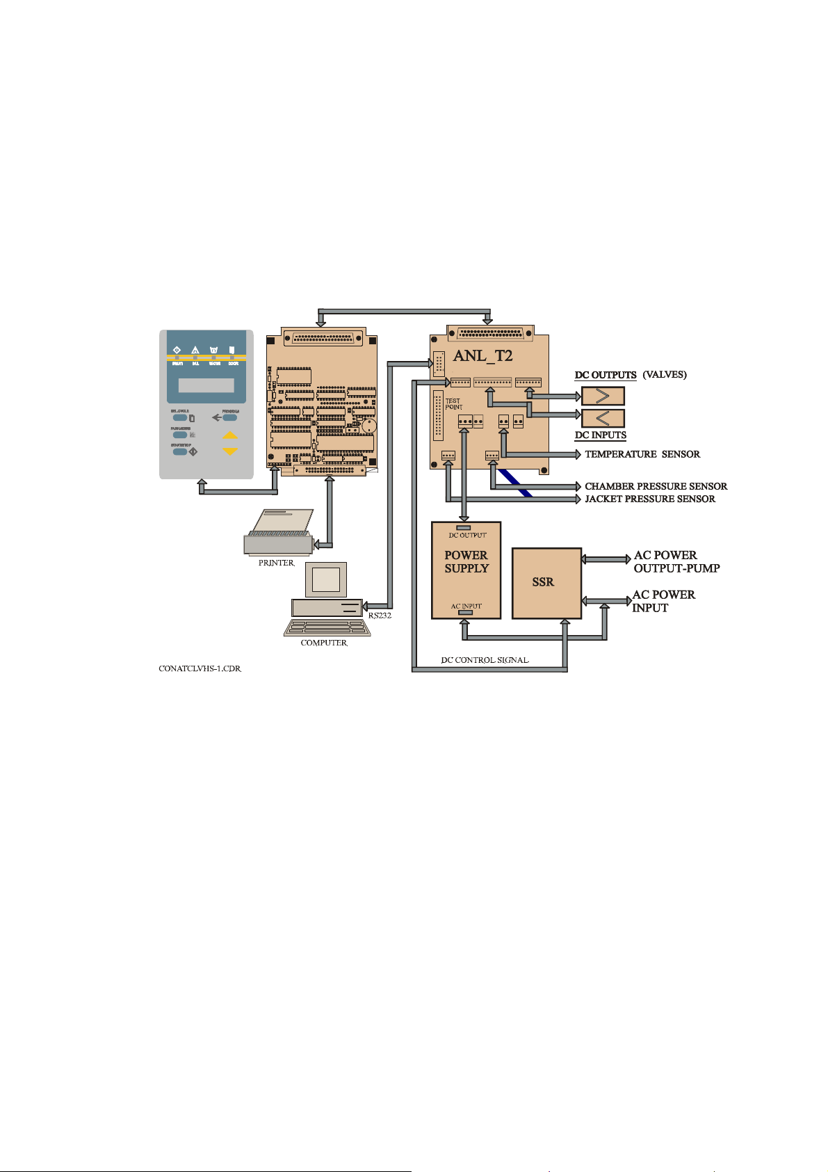
5. DESCRIPTION OF THE CONTROL SYSTEM.
(See CDR Control diagram).
The control system is based on 3 electronic boards designed according to the
autoclave requirements, the digital board DIG-T2 containing the microcontroller memories, buffers and digital ICs and the analog board ANL-T2
which performs the processing of signals coming from the sensors and switches.
The AC-T1 board consists of filters and AC drivers. DC voltages 12V and 5V,
supplied by a switching type power supply, powers the 3 electronic boards.
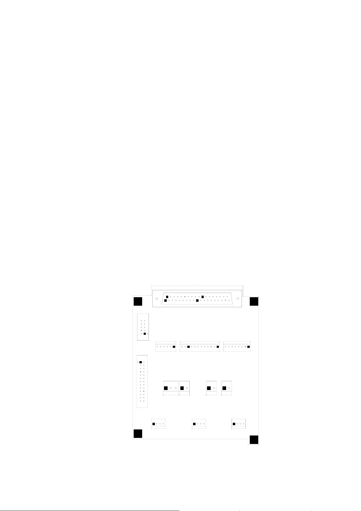
CONTROL SYSTEM BLOCK-DIAGRAM
PLUG
SKT
20
1
DIG-T2 BOARD
C2
+
U12
R3
C9
R2
U16
R1
U11
U14
C5
U21
U17
DIG T3
U22
97-05
C24
C25
8
C23
1
JP3
C22
2
DS1
1
37
JP1
19
U8
U3
C3
+
RP1
U15
R9
D1
C15
U1
C7
U18
C4
R4
U4
C16
C17
Q1
Y1
BZ1
U19
C6
34
33
20
1
P1
1
JP7
JP2
JP3
1
1
JP12
1
37
19
JP1
12
1
JP6
JP5
JP4
1
JP8
1
1
JP9
JP10
1
The system is provided with communication interfaces RS 232 to PC and to
parallel printer.
5.1 Digital Board DIG - T2
— The digital board is connected to the keypad panel, to the parallel
printer and to the analog board ANL-T2.
— The board contains the micro-controller (U15) type 80C32 that runs
the software program of the system.
— On the board, are three types of memories:
1) EPROM memory (U17), part no. 27512 storing the program
codes.
2) RAM memory (U21) with a capacity of 32KB for the temporary
data during the running of the program.
3) EPROM memory (U22) that is a fixed serial memory with an
electrical writing and erasing.
— This EPROM serves as a non-volatile memory, enabling the system
to change follow-up tables during running of program codes, and
ensuring this data is not lost in case of power failure.
7
Page 10
www.shanghaidelan.com
— The board contains an optimal Real Time Clock (U12), which serves
as a clock to the system, including a back-up battery, which ensures
the clock, runs continuously even when the autoclave is not
powered.
This component is optimal because it is related to the operation of
the printer, which is also an optional item.
— The board contains a watchdog, which detects any faulty situation in
the running program code. It performs an automatic reset of the
micro-controller and stops all the commands to avoid an
uncontrolled activation of any of the heating elements or the valves.
— The board functions as an MMI (Man-Machine Interface). It is
connected to a LCD display of two rows with 16 characters on each
row and to the following light indicators:
— START (autoclave in process),
— FAIL (the process failed),
— WATER (no water in the reservoir),
— DOOR (the door is not closed).
A keyboard connected to the digital board, serves as a control panel
containing the command and programming keys.
— The digital inputs and outputs are transferred to the system, as
follows:
— Through the digital board to the analog board by means of buffers
74HC377.
— RS232 interface is performed on the board by the U13 component,
the signal is transmitted to the communication connector located on
the ANL-T2 board.
— The printer is connected directly to this board, connector DS1
enables to connect the DPU-20 printer manufactured by SEIKO.
The printer receives the data and the supply voltage directly from
this connector.
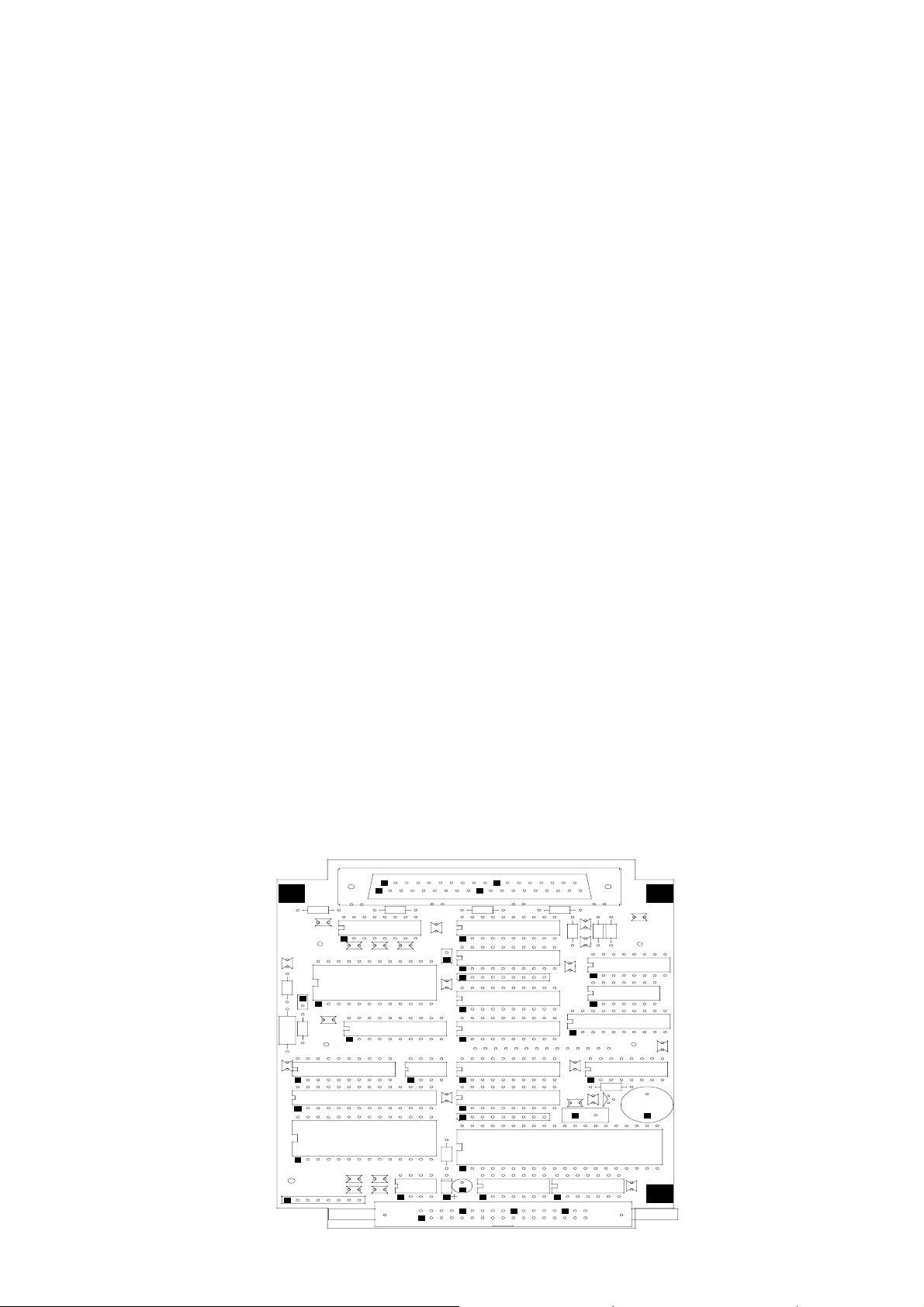
The layout of the DIG-T2 board components is provided below
DIG- T2 BOARD
SK
+
C5
C2
R3
R1
C1
R2
R8
U1
U1
C1
C9
U1
U1
20
1
R7 R6
C1
U1
C1
C1
U5
U1
JP
C8
U7
R5
RP
U8
U3
C1
R1
U6
C4
37
19
+
U2
C1
C2
R1
U1
JP1
C2
R1
U2
C7
R4
U2
U1
H2
1
DIG
97-05
JP3
C2
C2
+
C3
RP
U1
R9
U2
C2
8
C2
DS
D1
C1
2
1
U1
Y1
U4
C1
C1
Q1
BZ1
U1
C6
34
33
8
Page 11
www.shanghaidelan.com
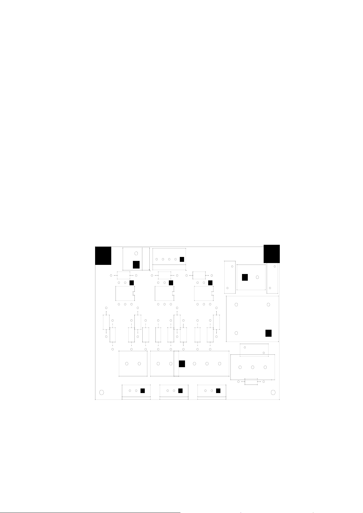
5.2 Analog Board ANL-T2
The analog board contains the drivers of the valves, heaters and pump. It
contains the sensors circuits connected to the control system, and serves
as a junction to the autoclave connections.
The input is 12VDC & 5VDC and the output is for all the signals to the
autoclave.
— The power supply provides the DC voltages 12V and 5V through the
connector JP3 to the board and further to the DIG-T2 board.
— The computer is connected to the board through the connector P1, by
RS232 interface.
— The analog and digital inputs, from the temperature sensor, electrode
door switch, etc. are connected through connector JP6, the
conversion circuits of the sensors are located on this board.
— The pressure sensor MPX2200 that measures the chamber pressure is
connected to the board through connector JP8, to the conversion
circuit of the sensor that is located on this board.
— The analog to digital conversion circuit A/D (U5) and the analog
multiplexer (U6) for 8 analog inputs (temperature, pressure, and
electrode) are located on this board and transfer digital signal to the
DIG-T2 board.
— All the drivers and power circuits to the solenoids (valves, door
locking) are included on this board.
Layout diagram of the ANL-T2 is provided below.
ANL - T2 BOARD
PLUG
P1
JP2
JP12 JP8
1
ANL T1 BOARD
20
1
JP1
1211
1
JP4
JP5
JP9
1
1
JP7
JP3
1
1
37
19
JP6
JP10
1
JP11
1
9
Page 12
www.shanghaidelan.com
5.3 AC - Board - AC-T1
This board receives command signals from ANL-T2 board designated to
activate AC devices. It converts them to AC mode.
The AC-T1 board provides AC filtering for the power supply to the
control system and protection from sharp current fluctuations.
The AC-T1 board includes:
— AC drivers for the AC devices (pump, heaters, etc.) up to 6A.
— AC - input connector JP3.
— Filter circuit based on L1C5, the power transfer from the filter to
power supply via JP2.
— Spike protection - RV1÷3.
— Three - 230/115 VAC output channels, triac control circuit.
Q1 - 16Amp - JP4/1,2
Q2 - 8 Amp - JP7/1
Q3 - 8 Amp - JP7/2
AC-T1 BOARD
(JP3,JP4,JP7 ON THE BOTTOM SIDE OF THE BOARD)
JP5
R9
U3
R12
C3
Q3
R11
JP7
1
R10
R8 C2
U2
JP1
R5
R6
R7 C1
R4
JP4
1
Q2
1
U1
R1
Q1
R3
RV3 RV2
JP2
R2
L1
JP6
JP3
C5
ETYPEAC-97
CAT TECH.
RV1
10
Page 13
www.shanghaidelan.com
6. CALIBRATION OF TEMPERATURE AND PRESSURE
6.1 Method of Calibration:
The calibration of temperature and pressure is performed digitally.
The temperature and pressure measuring circuits are designed with
components having 1% accuracy.
The temperature circuit is linear and has an output of 100mV÷2400mV
for a temperature range 20°C÷150°C.
The pressure circuit is also linear and has an output of 100mV÷2400mV
for a pressure range 0÷400 kPa.
The measuring at the A/D is limited for values higher than 2400mV or
below 100mV.
The system has a non-volatile memory in which the offset and gain data
of the sensors are stored.
Calibration is performed by use of the keyboard (or the communication
port for computer use).
Following is a description of the calibration of temperature and pressure
using the keyboard. The calibration procedure is identical to all autoclave
models.
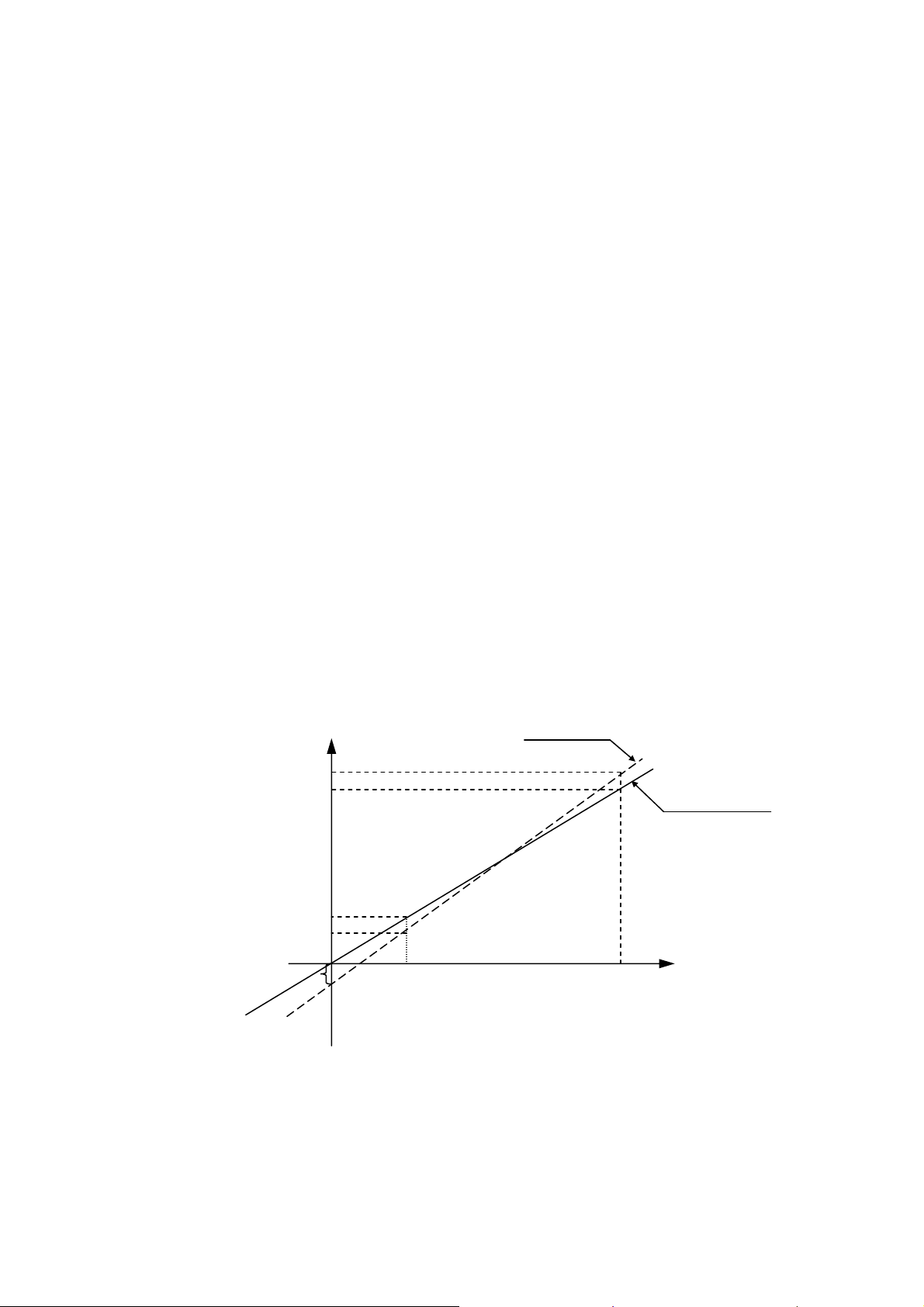
Definition of Gain and Offset:
Every straight line can be defined by the equation ax+b=y. “a” is the
deviation from y=0 and “b” is the slope of the line. In our case a=Gain
and b=Offset.
The system is based on calculation of offset and gain of two points as in
the following example
If the actual measured pressures are 100 kPa & 300 kPa and the
displayed pressures are 90 kPa & 310 kPa respectively, the ‘input Vs
pressure” graph will be as follows.
READ
310
300
Y
ACTUAL
100
90
PRESURE
a
V
1
X
INPUT FROM SENSOR
V
2
The calibration method enables to input this data into the system in order
to perform automatic correction of OFFSET and GAIN.
It is necessary to define the two points, which have to be input to the
system, prior to performing calibration.
11
Page 14

www.shanghaidelan.com
6.2 Temperature Calibration Procedure
— Press the PROGRAM
— The system enables to set the system’s date the time.
— This operation is skipped by pressing PROGRAM key
six times.
— CODE: ∅∅∅ will be displayed.
— Select Technician Code (011) by the UP/DN keys and press the
PROGRAM
— Select CALIB CODE: 107 to calibrate the system by means of the
UP/DN keys and press the PROGRAM key again until TEMP
CAL: ∅∅∅ will be displayed.
— Set calibration code to TEMP CAL: ∅∅1
— Press the PROGRAM
— The following data will be displayed:
UPPER ROW: A 60.0 R 60.0
LOWER ROW: A 130.0 R130.0
Enter the actual data (A) and the displayed data (R) for two known points
as in the following example:
The actual temperatures are 70°C & 120°C and the displayed
temperatures are 68°C & 120°C respectively.
Proceed as follows:
— On the upper row, change A60.0 to A 70.0 by means of UP/DN
keys.
key.
key.
key again and do not change the code.
— Press the PROGRAM
— The cursor on the upper row will move to R60.0, change to R68.0 by
means of UP/DN keys.
— Press the PROGRAM
— The cursor moves to the lower row to A 130.0
by means of UP/DN keys.
— Press the PROGRAM
— The cursor on the lower row will move to R130.0, change to R123.0
by means of keys UP/DN, then press the PROGRAM
This completes calibration procedure for temperature.
key.
key.
, change it to A 120.0
key.
key
12
Page 15

www.shanghaidelan.com
Remarks:
— When cursor is set under any figure, pressing the START/STOP
key stops calibration.
— When the cursor is set under any figure, it enables to feed this value
to the reading of temperature by pressing the PARAMETERS key.
Example:
If the cursor is set under R68.0 on the upper row and the actual
temperature of the autoclave is now 66.0ºC, by pressing the
PARAMETERS
R68.0 to R 66.0.
This calibration method enables the technician to change a certain point
without affecting a second point.
Example:
When the working temperatures are 134ºC and 121ºC but the actual
temperature are 132ºC and 121ºC
The measured temperature for 134ºC must be corrected without
changing the temperature at 121ºC,
Considering the above example, the setting of data can be done as
follows:
A 121.0 R 121.0
A 132.0 R 134.0
The system will calibrate the new offset and gain and retain them into the
non-erasable memory.
As a result, while running a 134ºC program the correction is
automatically made, while at 121ºC no change is felt.
key, the temperature reading will be corrected from
13
Page 16

www.shanghaidelan.com
6.3 Pressure Calibration Procedure
To perform the pressure calibration two points have to be defined
allowing the calculation of new OFFSET and GAIN values.
— Press the PROGRAM
key.
— Skip date and the time setting by pressing the PROGRAM key
six times.
— CODE: ∅∅∅ will be displayed.
— Select the Technician Code (011) by the UP/DN keys and press the
PROGRAM
key.
— Select CALIB CODE: 107 to calibrate the system by means of the
UP/DN keys and press the PROGRAM key again until the
system displays: PRES CAL: ∅∅∅
— Press the PROGRAM
key.
The following is displayed:
Point 1 – Upper Row A 100 R 100
Point 2 - Lower Row A 300 R 300
— Open the door, do not alter A 100.
— Press the PROGRAM key, the cursor will move to R
100.
— Press the PARAMETERS key. The system performs reading
pressure and displays it instead of R100. E.g. R97 (i.e. the system
reads out 97kPa, when the door is open).
— Press the PROGRAM
key.
— The cursor moves to the lower row to A300.
If the system reads out 280kPa, do not change A300. Press the
PROGRAM
key to move to R300 and change it to the actual
pressure value 280kPa by means of the keys UP/DN.
— Press the PROGRAM
key again.
The system calculates the new values for offset and gain and stores
these values in the non-volatile memory.
This completes the calibration procedure for the pressure.
14
Page 17

www.shanghaidelan.com
7. TEST POINTS
The test point list provides testing points on the junctions on board to assist in
locating the malfunction.
NU TP FUNCTION VALVE
TP1
TP2
TP3
TP4
TP5
TP6
TP7
TP8
TP9
TP10
TP11
TP12
TP13
TP14
TP15
GND
+5V DC
+12V DC
OUT - HEATERS ‘0’V-Off 5V-On
OUT-AIR-VALVE 0V-Off 5V-On
OUT-EXH-VALVE 0V-Off 5V-On
OUT-WATER-VALVE 0V-Off 5V-On
OUT-DRY-VALVE 0V-Off 5V-On
OUT-DOOR-VALVE 0V-Off 5V-On
TP16
TP17
TP 18
TP19
TP20
TP21
TP22
TP23
TP24
TP25
TP26
IN-TEMPERATURE
0÷2.5V
IN-PRESSURE
IN-ELECTR. 2.5V NO WATER
0 ÷2.5V
15
Page 18

www.shanghaidelan.com
8. SOFTWARE PROGRAMMING PROCEDURES
8.1 General
The software for the control system of E-Type autoclaves is AS
FOLLWS:
EaEn3WP20 for standard autoclaves.
EaEn3WP20AR for autoclaves designed to operate at high altitude
(above 2500 m.
The software contains a table of parameters of which part of them defines
the autoclave, and part defines the processes in the autoclave. This
document describes parameters and their task in the software.
8.2 Changing Cycle Parameters
Access to the program is achieved by inserting the access code.
Access code 1 – This access code enables change of the sterilization
time, sterilization temperature and the drying time.
Access code 11 – changes that may be done by the supervisor.
Enables to change a few parameters
Access code 33 – changes that may be done by the technician.
Enables to change all the parameters
To change the parameters listed below, proceed as follows:
a. Select the cycle.
b. Enable the operation by entering the ACCESS CODE (11).
c. Set the parameter that has to be modified, by pressing successively
the PROGRAM key.
d. Set the desired data by means of the UP/DN keys.
e. Pressing the PROGRAM key enters the modified data into memory,
and moves to the next parameter.
The pre-set parameters values will replace the last default values and
become the updated default values.
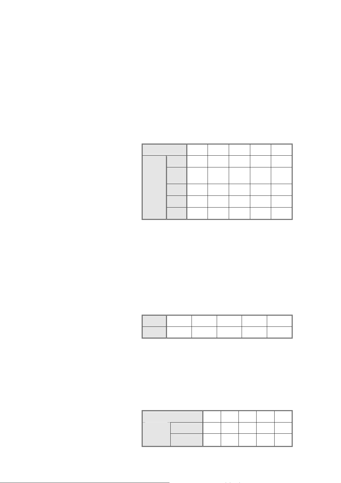
8.2.1 SteTemp – Required sterilization temperature for the process
Entry Code – 1
Resolution – 1ºC
Minimum value for the change – 60ºC
Maximum value for the change – 137ºC
Set value
Cycle
Value
8.2.2 SteTime – Required sterilization time for the process
Entry code – 1
1 2 3 4 5
134 121 134 121 121
Resolution – 1 minute
Minimum value – 3 minutes
Maximum value – 99 minutes
Set value
Cycle
Value
1 2 3 4 5
3 15 7 20 30
16
Page 19

www.shanghaidelan.com
8.2.3 Heat Standby – Heating elements operation in Standby Mode
Access Code – 1
Resolution – 1
Value – 0 or 1
— If Heat Standby = 0, the heating elements will not
operate in the Standby Mode.
— If Heat Standby = 1, the heating elements will operate in
the Standby mode, in a shoot mode of 1 second on, 59
seconds off.
8.2.4 Dry Time – Required drying time for the process
Entry Code – 1
Resolution – 1 minute
Minimum Value – Ø minutes
Maximum Value – 99 minutes
Cycle
Set value
8.2.5 Heat T.O. - Maximum time allowed for the heating stage
(testing)
After this time, if the system does not enter the sterilization stage,
it will receive a ‘Low Heat’ message and the process will abort.
Entry Code – 11
Resolution – 1min
Minimum Value – 20min
Maximum Value – 120 min
Set value
8.2.6 Ex Mode – The method for exhausting the steam at the end
of the process
Entry Code – 11
Value
per
model
Cycle
Value
E, EK
EA, EKA
1 2 3 4 5
60 60 60 60 90
1 2 3 4 5
0 0 30 30 0
1 1 30 30 0
Resolution – 1
Ex Mode
Fast Ex 1
N.A. 2
Slow Ex (Waste) 3
Slow Ex (Liquids) 4
Set value
Cycle
Value
1 2 3 4 5
1 1 1 1 4
17
Page 20

www.shanghaidelan.com
8.2.7 End Temp - The ending temperature of the process
If at the end of the process the temperature is higher than this
temperature, the process will not end and the door will remain
closed.
Entry Code – 11
Resolution – 1ºC
Minimum Value – 40ºC
Maximum value – 137ºC
Set value
Cycle
Value
8.2.8 Air Temp – Controls the closing of the air valve
Defines the temperature of the chamber’s outlet at which the
valve closes.
Access Code - 11
Resolution - 1
Minimum Value - 50°C
Maximum Value - 99°C
Factory pre-set 90°C
Cycle
Set value
Value
8.2.9 Calib Code – Calibration Code
This allows entry to the calibration mode.
It must be set on 107 in order to allow the code to be entered.
1 2 3 4 5
125 121 125 134 95
1 2 3 4 5
90 90 90 90 90
Entry Code – 11
Resolution – 1
Minimum Value – Ø
Maximum Value – 255
Set value
Cycle
Value
1 2 3 4 5
100 100 100 100 100
18
Page 21
www.shanghaidelan.com
8.2.10 Water Time – Time for entering water to the autoclave
This value defines the entry time of the water to the autoclave to
locate the electrode touching the water.
This time will change from process to process and even for
different autoclaves.
When the autoclave is vertical and the defined time is Ø
seconds, the water valve will not open at all.
Entry Code – 11
Resolution – 1 second
Minimum Value – 1 second
Maximum Value – 90 seconds
Cycle
1730
2340
Set value
8.2.11 LimitP add – The allowable addition to the maximum
pressure in every process
If the maximum pressure is 225kpa, the system will not heat
beyond this pressure. If LimitP add will be Ø, the maximum
pressure will remain 225kpa. If LimitP add equals 10, the
maximum pressure will be 235kpa.
Entry Code – 11
Resolution – 1kpa
Minimum Value – Økpa
Maximum Value – 30kpa
Value
per
model
2540
3140
3850
3870
1 2 3 4 5
50 50 50 50 50
30 30 30 30 30
40 40 40 40 40
45 45 45 45 45
60 60 60 60 60
Set value
8.2.12 EA Type – The autoclave contains a drying pump for the Dry
Stage
Access Code – 33
Resolution – 1
Value – 0 or 1
Autoclave contains Drying Pump = 1
Autoclave does not contain a Drying Pump = 0
Set value
Cycle
Value
Cycle
Value
per
model
1 2 3 4 5
0 0 0 0 0
1 2 3 4 5
E, EK
EA, EKA
19
0 0 0 0 0
1 0 0 0 0
Page 22

www.shanghaidelan.com
8.2.13 Req Prs+
This defines the required addition to the sterilization pressure in
kpa.
For example, for a sterilization temperature of 121ºC the
required pressure is 204kpa. Since the system controls the
sterilization process according to pressure and temperature, if
Req Prs+ equals Ø, the system will maintain the pressure at
204kpa. If the value is at 5kpa, the system will be maintained at
209kpa, and so on.
Entry Code – 33
Resolution – 1
Minimum Value – 0kpa
Maximum Value – 15kpa
Cycle
1730
Set value
8.2.14 Auto. Num – Autoclave serial number
This parameter is used to set the serial number in the facility.
This number enables the operator to identify each autoclave.
This number is printed on the autoclave’s printout.
Access Code – 13
Resolution – 1
Minimum Value – 1
Maximum Value – 99
8.3 Resetting the Autoclave
Whenever certain data, stored in the back-up memory, must be erased the
system must be reset, in order to restore the system to normal operation
or for situations that follow:
Value
per
model
2340
2540
3140
3850
3870
1 2 3 4 5
7 5 7 5 5
9 9 9 9 9
— When the machine is operated for the first time or after a long
interruption, and disorders appear in the operations sequence.
— When operation was stopped in the middle of the cycle, as a result of
a power failure or manual stop and the cycle has not been completed.
To reset the system; proceed as follows:
— Turn the main power switch OFF.
— Turn the main power switch ON, while pressing the SEL. CYCLE
key, until the program parameters are displayed.
After resetting the autoclave, the autoclave is in stand-by mode
20
Page 23

www.shanghaidelan.com
9. REPLACEMENT OF COMPONENTS
9.1 Safety Tests after Repair
ATTENTION!
After every repair or dismantling the enclosure, the autoclave should
pass two safety electrical test by the Service Engineer. The following
shall be performed:
1. Enclosure Leakage Current Test.
Every autoclave should pass this test as follows:
1. Remove the outer cover (see para. 9.2 “Dismantling the Outer
Covers of the Autoclave”).
2. Disconnect receptacle from JP3.
3. Remove all fuses
4. Connect the electrical cord to the autoclave.
5. Turn on the circuit breaker.
6. Short-circuit the L and N pins on the cord's plug.
7. Connect the Short-circuit pins to the L pole on the Megger.
8. Connect the earth pins to the earth pole on the Megger.
9. Impose an electrical potential of 500-1000V on the tested
autoclave. The insulation resistance should be at least 2 MΩ.
The test is successful if there was no leakage.
2. Protective Earth Impedance Test
1. Connect the grounding pin of the power cord plug to one pole of
an Ohmmeter.
2. Connect any other metallic part (preferable – the metallic part of
the locking screw) to the second pole of the Ohmmeter.
3. The resistance should not exceed 0.3 Ω.
After performing these tests, the Service Engineer should complete and
sign the Work Order.
21
Page 24
www.shanghaidelan.com
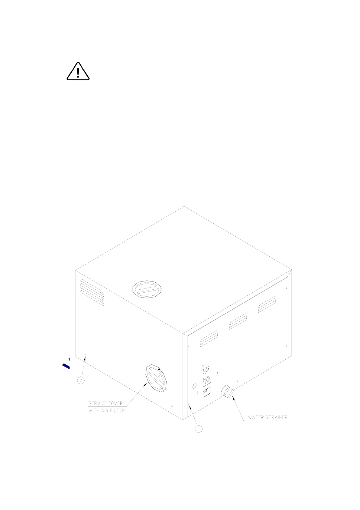
9.2 Dismantling the Outer Covers of the Autoclave
Caution!
Before starting, disconnect the instrument from the power source and
ensure that there is no pressure in the autoclave.
Allow the autoclave to cool before removing outer covers.
1. Remove the screws holding the rear cover (1).
2. Remove the screws holding the cover to the base (2).
3. On EA and EKA models dismantle the air filter from the service
opening cover (3).
3.1. Remove the screws holding the filter cover (on EA, EKA).
4. Remove the grounding wires from the cover.
5. Pull the cover upwards.
22
Page 25
www.shanghaidelan.com
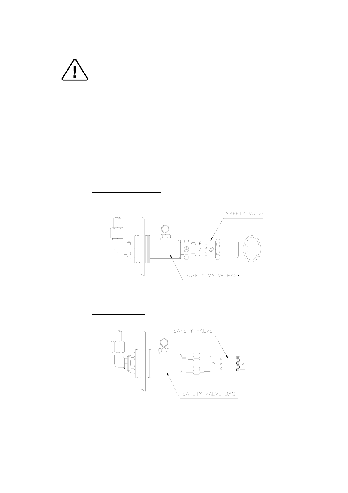
9.3 Replacing the Safety Valve
Caution!
Before starting, be sure that the electric cord is disconnected and that
there is no pressure in the autoclave.
Note:
These instructions are valid for both, PED and ASME type safety
valves.
1. Remove the autoclave cover (see para. 9.2 “Dismantling the Outer
Covers of the Autoclave”).
2. Remove the water reservoir cover.
3. Unscrew the safety valve and remove it from the safety valve base.
4. Replace the valve with a new safety valve (install an original only!).
use Teflon tape for sealing the thread.
5. Perform one cycle and verify that the valve operates correctly.
ASME approved Type
CE marked Type
23
Page 26

www.shanghaidelan.com
9.4 Replacing the Air Jet
Caution!
Before starting, be sure that the electric cord is disconnected and that
there is no pressure in the autoclave.
1. Remove the autoclave cover (see para. 9.2 “Dismantling the Outer
Covers of the Autoclave”).
2. Remove the water reservoir cover.
3. Remove the water reservoir silicon gasket.
4. Unscrew the air Jet with a 10 mm wrench and remove it from the
safety valve base.
5. Replace the valve with a new air Jet (install an original only!). use
Teflon tape for sealing the thread.
6. Test any autoclave cycle to verify that the valve operates correctly.
AIR JET
24
Page 27

www.shanghaidelan.com
9.5 Replacing the Air Relief-safety relief Valve block
Caution!
Before starting, be sure that the electric cord is disconnected and that
there is no pressure in the autoclave.
In case the water reservoir is deeply contaminated (soil, lime stone.
etc.) it is recommended to replace the entire unit.
1. Remove the autoclave cover (see para. 9.2 “Dismantling the Outer
Covers of the Autoclave”).
2. Remove the water reservoir cover.
3. Remove the water reservoir silicon gasket.
4. Unscrew and remove nut (1) with a ½” wrench.
5. Remove angle 1/8”-1/4” (2) from the relief valve base.
6. Unscrew and remove nut (3).
7. Remove the air-relief-safety valve block (4).
8. Install the new unit using Teflon tape for sealing the thread.
9. Perform one cycle and verify that the valve operates correctly.
25
Page 28

www.shanghaidelan.com
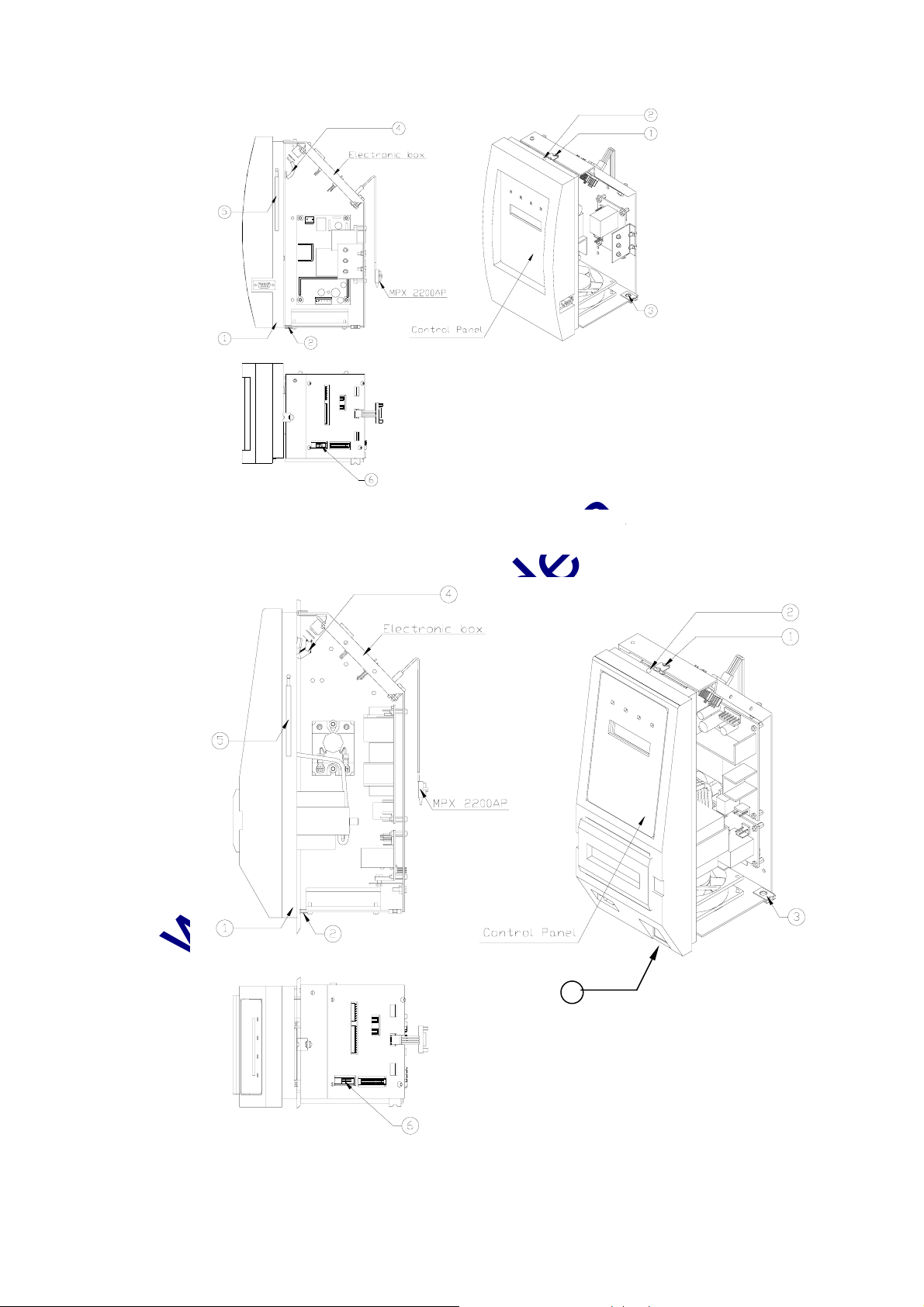
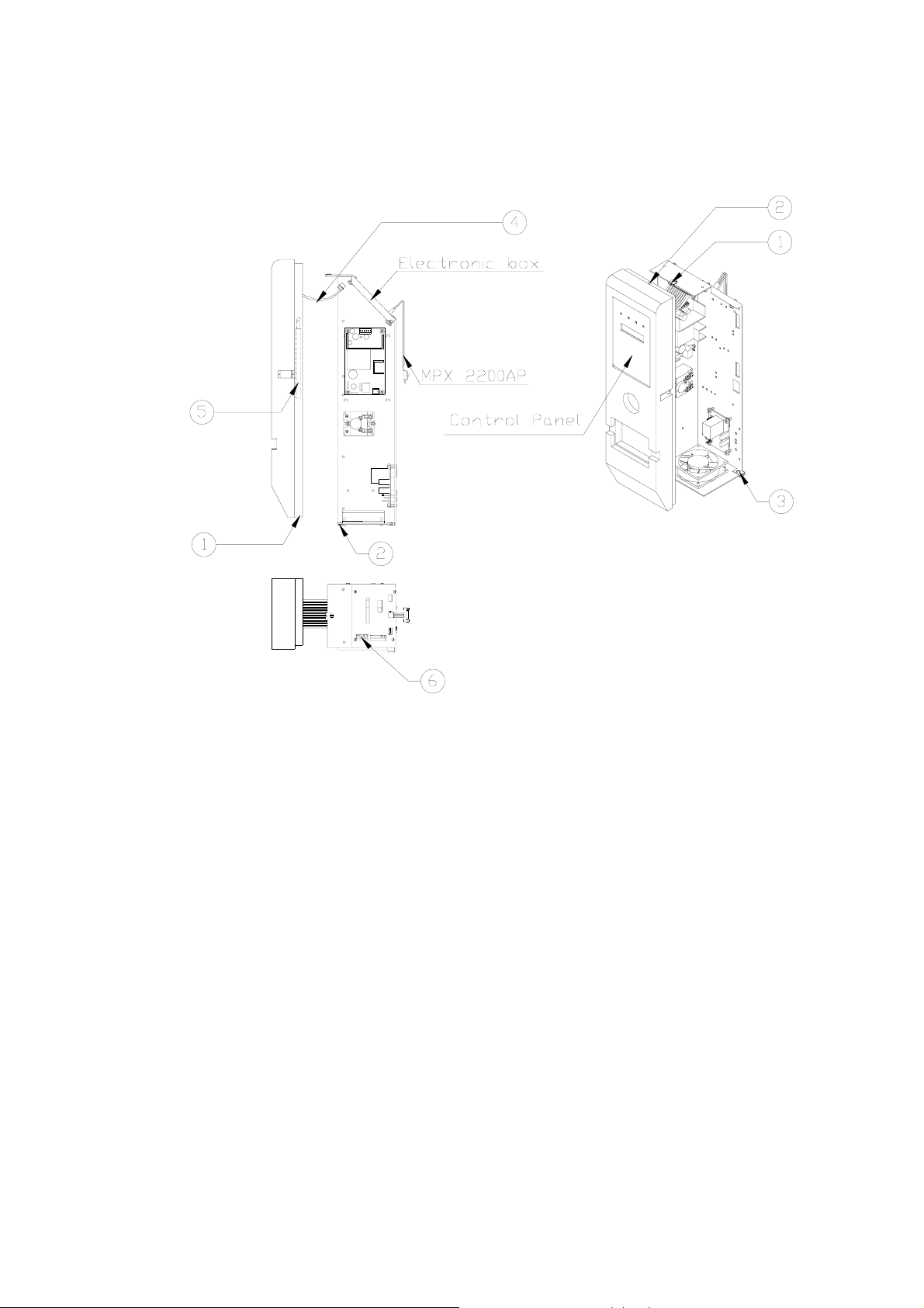
9.6 Replacing the electronics board (control panel)
Caution!
Make sure that the power cord is disconnected!
If the electronic box was damaged by any liquid that entered the box, do
not attempt to replace it. In this case only the factory technicians may
repair the autoclave.
Allow the autoclave to cool before removing outer covers.
1. Remove the autoclave cover (see para. 9.2 “Dismantling the Outer
Covers of the Autoclave”).
2. Remove the two screws that connected the plastic panel with the
digital electronic board to the autoclave (2).
3. Disconnect the flat cable from JP1-DIG-T2 to JP1 ANL-T2 (4).
4. Disconnect the flat cable of communicator from P1-ANL-T2 (6).
5. Disconnect the grounding cable shoe (5).
6. On autoclave models 2340 and 2540 disconnect the main switch.
7. Remove the plastic panel, including the electronics board (control
panel), from the autoclave.
8. Disconnect the control panel from the plastic panel and replace it
with a new one.
9.7 Replacing the Electronics Box
Caution!
Make sure that the power cord is disconnected!
If the electronic box was damaged by any liquid that entered the box, do
not attempt to replace it. In this case only the factory technicians may
repair the autoclave.
Allow the autoclave to cool before removing outer covers.
1. Remove the autoclave cover (see para. 9.2 “Dismantling the Outer
Covers of the Autoclave”).
2. Remove two screws from the bottom side and from the top (1, 3).
3. Disconnect all the electric system connectors from the electronics
base (including the MPX connectors).
4. Remove electronics box and replace with new one.
5. Re-assemble the instrument. Verify that the grounding connections
are connected correctly.
6. Test any cycle and verify that the autoclave operates as required.
26
Page 29
www.shanghaidelan.com
Electronic box: 1730
7
Electronic box: 2340/2540
27
Page 30
www.shanghaidelan.com
Electronic box: 3140/3850/3870
28
Page 31

www.shanghaidelan.com
9.8 Replacing Heating elements
Caution:
Before starting, be sure that the electric cord is disconnected from the
power source and that there is no pressure in the autoclave chamber.
1. Remove the autoclave cover (see para. 9.2 “Dismantling the Outer
Covers of the Autoclave”).
2. Remove the insulation.
3. Remove the heating element tightening bolts (1).
4. Release the two terminal wires from the heating element.
5. Replace the heating element (s)
5.1 Verify that the upper thermo-couple tube is connected to the
upper (cut-off) thermostat and that the lower thermo-couple tube
is connected to the lower (safety) thermostat.
6. Ensure that the heating element strap is well tightened to the
autoclave body, ensuring proper heat dissipation from the heating
element.
7. After replacing one or more heating elements run a cycle and verify
that it operates as required.
8. Retighten the fixing screws of the heaters. This operation is done
with the autoclave hot, but with the power cord disconnected from
the power outlet and autoclave door open, to ensure that the chamber
is not pressurized.
9. Re-assemble the autoclave insulation and cover.
29
Page 32

www.shanghaidelan.com
9.9 Replacing the Temperature Safety Thermostat
The autoclave is supplied with a temperature thermostat, which protects
the heaters and autoclave against overheating, during the dry cycle.
This device reconnects automatically when the chamber cools down.
Caution
Before starting, disconnect the instrument from the power source and
ensure that there is no pressure in the autoclave.
Allow the autoclave to cool before removing outer covers.
The temperature safety thermostat is located on the lower side of the fuse
and socket panel on the rear of the autoclave.
1. Remove the rear cover.
2. Loosen the heating band.
3. Unscrew the thermostat and replace it with a new one.
4. Perform any dry cycle to verify that the temperature safety
thermostat disconnects the heating units.
(ON EA, EKA MODELS)
30
Page 33

www.shanghaidelan.com
9.10 Replacing the Cut-Off Thermostat
This thermostat cuts out power to the autoclave, in the event that all other
safety means do not function.
For example: If the safety thermostat is defective and the temperature
continues to rise, then the cut-off thermostat cuts out the power to the
autoclave. In order to restart the operation press the Reset Button. If the
autoclave is operated according to the instructions, and the thermostat
again cuts out, the Cut-Off Thermostat must be replaced.
Caution
Before starting, disconnect the instrument from the power source and
ensure that there is no pressure in the autoclave.
Allow the autoclave to cool before removing outer covers.
The Cut-Off Thermostat is located on the upper side of the fuse and
socket panel on the rear of the autoclave.
1. Remove the rear cover.
2. Loosen the heating band.
3. Unscrew the thermostat and replace it with a new one.
(ON EA, EKA MODELS)
31
Page 34

www.shanghaidelan.com
9.11 Cleaning and Replacing the Water Level Electrodes
The water level electrode is located at the rear bottom area of the
chamber.
9.11.1 Replacing
Caution
Before starting, disconnect the instrument from the power
source and ensure that there is no pressure in the autoclave.
Allow the autoclave to cool before removing outer covers.
1. Remove the rear cover.
2. Disconnect the wire from the electrode connection.
3. Open the nut that tightens the electrode.
4. Insert a new electrode and tighten the fixing nut to avoid
leakage.
5. Reconnect the wire to the electrode.
6. Test the unit.
9.11.2 Cleaning
1. Pull out the trays and tray holder.
2. Clean the electrode tip.
3. Test the unit.
Water level electrode assembly
Cat No. CMT196-0004
32
Page 35

www.shanghaidelan.com
9.12 Replacing the Drain Valve
Caution!
Before starting, disconnect the instrument from the power source and
ensure that there is no pressure in the autoclave.
Allow the autoclave to cool before removing outer covers.
1. Remove the autoclave cover (see para. 9.2 “Dismantling the Outer
Covers of the Autoclave”).
2. Disconnect the drainpipe from the valve, using a 9/16” wrench.
3. Remove the nut (3) and the “ring for drain valve” (2).
4. Remove the drain valve (1) from the panel.
5. Install a new valve according to the drawing below.
6. Verify that there is no leakage.
CMT240-0020 CMT240-0003 VLV170-0066
Item Cat No.
1 GAS082-0020
2 GAS082-0021
33
Page 36

www.shanghaidelan.com
9.13 Replacing the Pressure Gauge
Caution!
Before starting, disconnect the instrument from the power source and
ensure
that there is no pressure in the autoclave.
9.13.1 Models 2340, 2540
1. Remove the door cover (see para. 9.20 “Dismantling the
Autoclave’s Door Cover”).
2. Remove the pressure gauge from the door.
3. Install the new pressure gauge using Teflon tape for
sealing the thread. Verify that the gauge’s tube does not
protrude from the door inner surface.
4. Operate the autoclave and verify that there is no leakage.
5. Install the door cover.
9.13.2 Models 3140, 3850, 3870
The gauge is located in adjacent to the electronic box
1. Remove the autoclave cover (see para. 9.2 “Dismantling
the Autoclave’s Outer Covers”).
2. Remove the pressure gauge.
3. Install the new pressure gauge using Teflon tape for
sealing the thread.
4. Reassemble the electronic box and the control panel.
5. Reassemble the autoclave’s cover.
6. Operate the autoclave and verify that there is no leakage.
34
Page 37

www.shanghaidelan.com
9.14 Replacing the Locking Solenoid
Caution!
Before starting, disconnect the instrument from the power source and
ensure that there is no pressure in the autoclave.
1. Remove the door cover.
2. Disconnect the wires from the connector.
3. Unscrew the tightening nut (cat. No. CMV100-0002 or
CMT201-0005 as appropriate).
4. Remove the pin, the spring and the solenoid.
5. Replace the damaged items and reinstall according to drawing
below.
6. Operate the autoclave and verify that the pin is retracted when the
cycle reaches “stand-by” stage.
For models
1730, 2340, 2540
For models
3140, 3850, 3870
35
Page 38

www.shanghaidelan.com
9.15 Replacing the Printer
9.15.1 DPU20 Printer
Caution!
Before starting, disconnect the instrument from the power
source.
1. Remove the autoclave cover (see para. 9.2 “Dismantling
the Outer Covers of the Autoclave”).
2. Disconnect the connector of the flat cable (1) connecting
the electronic box to the printer (2).
3. Unscrew the two screws (3) attaching the fastening
bracket (4) to the printer.
4. Remove the printer and insert the new one.
5. Assemble the fastening bracket to the printer with the two
screws (2) and verify that it "sits" firmly in its seat.
6. Connect the flat cable (1) to the printer.
7. Verify connection of power by performing a self-test.
8. Run a cycle and verify that the printer operates correctly.
No. Cat. No. Description
1 WIR040-0070 Cable, Flat, Printer, DPU20, 25CM, 34P
2 THE002-0005 Printer, DPU-20, Seiko
3 BOL190-0144 Screw, printer tightening
Supplied with
4
the printer
Fastening bracket
1
2
3
4
36
Page 39

www.shanghaidelan.com
9.15.2 DPU30 Printer
Caution!
Before starting, disconnect the instrument from the power
source.
1. Remove the autoclave cover (see para. 9.2 “Dismantling
the Outer Covers of the Autoclave”).
2. Disconnect the connector of the cable (1) connecting the
electronic box to the printer (2).
3. Unscrew the two screws (3) attaching the fastening
bracket (4) to the printer.
4. Remove the printer.
5. Set the dip switches on the new printer, located on the
back side of the printer, as follows:
1, 2, 3, 4,
up
6. Insert the new printer into its frame.
7. Assemble the fastening bracket to the printer with the two
screws (2) and verify that it is placed firmly.
8. Connect the (1) cable to the printer.
9. Verify connection of power by performing a self-test.
10. Run a cycle and verify that the printer operates correctly.
5, 6, 7, 8
down
up
9
10
down
1
2
3
4
No. Cat. No. Description
1 CTP201-0127 Cable, Printer, DPU-30, 30cm, 34p
2 THE002-0022 Printer, DPU-30, Seiko
3 BOL190-0144 Screw, printer tightening
Supplied with
4
the printer
Fastening bracket
37
Page 40

www.shanghaidelan.com
9.16 Replacing the Door Switch
Caution!
Before starting, disconnect the instrument from the power source and
ensure that there is no pressure in the autoclave.
Allow the autoclave to cool before removing outer covers.
1. Take off the autoclave cover (see para. 9.2 “Dismantling the Outer
Covers of the Autoclave ").
2. Disconnect the wires (1), (3) from the door microswitch (2).
3. Remove the microswitch and replace it with a new one.
4. Reconnect the black ground wire (3) to the microswitch.
5. Test the connection with an ohmmeter. Connect the ohmmeter to the
common terminal of the microswitch and chassis ground. In the
“door open” position the ohmmeter should show no continuity and in
“door close” position the ohmmeter should show a complete circuit.
5.1 If it fails the test then check that the ground wire is connected to
the correct terminal. If it is then replace the microswitch.
5.2 If it passes the test then connect the green wire from the
electronic box to the common terminal (1) of the switch
6. Reassemble the autoclave cover.
1
3
2
4
38
Page 41

www.shanghaidelan.com
9.17 Cleaning water inlet strainer
Caution!
Before proceeding, make sure that the electric cord is disconnected and
there is no pressure in the autoclave.
1. Remove the cover of the autoclave.
2. Drain the water from the water reservoir.
3. Remove the water filter from the silicon tube.
4. Open the filter by unscrewing the two filter parts.
5. Clean the filter by flushing it under running water for a few minutes.
6. Replace the filter parts and reconnect it to the silicon tube.
7. Open the water valve.
Water Reservoir Filter (FIL175-0020)
39
Page 42

www.shanghaidelan.com
9.18 Replacing the circuit breaker
Caution!
Before starting, disconnect the instrument from the power source.
1. Remove the autoclave cover (see para. 9.2 “Dismantling the Outer
Covers of the Autoclave”).
2. Disconnect the wires from the circuit breaker.
3. Remove the four screws connecting the circuit breaker to the panel
(1).
4. Replace the circuit breaker with a new one.
5. Reconnect the electrical wires.
6. Reassemble the cover.
7. Turn on the autoclave and verify it operates correctly.
8. Move the circuit breaker’s lever to the “tripped” position and verify
that the autoclave turns off.
Make sure that the correct circuit breaker is installed as marked in
para. 9.19 (Fuses and Circuit Breaker Data)!
1
40
Page 43

www.shanghaidelan.com
9.19 Fuses and Circuit Breaker Data
AUTOCLAVE TYPE
DESCRIPTION
Circuit breaker (A)
Air pump fuse (A)
Water pump fuse (A)
Circuit breaker (A)
Air pump fuse (A)
Water pump fuse (A)
Circuit breaker (A)
Air pump fuse (A)
Water pump fuse (A)
The drawing below refers to models EKA, EA. Models E, EK do not have an
air pump fuse. Model 1730 does not have any fuse.
E EA EK EKA
120V 230V 120V 230V 120V 230V 120V 230V
1730
15 10
15 10 15 10
1.25 1.25 1.25 1.25
15
1.25
2340/2540
3.15 1.25
3140/3850/3870
15
1.25
1.25
15 10
15
1.25
15
1.25
1.25
41
Page 44

www.shanghaidelan.com
0
9.20 Replacing the water pump
Caution!
Before starting, disconnect the instrument from the power source.
1. Remove the autoclave cover (see para. 9.2 “Dismantling the Outer
Covers of the Autoclave”).
2. Disconnect the wires from the pump
3. Empty the water reservoir.
4. Disconnect the piping from the pump.
5. Remove the pump from the rubber shock absorbers.
5.1 If the rubber shock absorbers are damaged, replace them. Note
that on models 2340/2540 the shock absorber’s bases are
pointed outward and on models 3140/3850/3870 they are
pointed inward.
6. Replace the damaged pump with a new pump.
7. Reconnect wiring and piping.
8. Reassemble the cover.
9. Turn on the autoclave and verify it operates correctly.
1
2
3
6
7
2340/254
No. Description 2340/2540 3140/3850/3870
Pump, Water, EX7, 230V 50/60HZ,
1
Ulka
2 Rubber shock absorber SKR203-0006 SKR203-0006
Hose adaptor, male, elbow, 1/8BSP,
3
for 6 mm Hose.
4 Screw
1 2
3140/3850/3870
PUM055-0006 PUM055-0006
FIT100-0806 FIT100-0806
BOL194-0342
3
4
5
6
5 Nut, Hex, Flange, 1/4NC
6 washer NUT193-0347 NUT193-0276
7 Rivet, Dome Head, Aluminum, 4x14 BOL194-0331
42
NUT192-0155
Page 45

www.shanghaidelan.com
9.21 Replacement of the Door Cover
Caution:
Before starting, be sure that the electric cord is disconnected from the
power source and that there is no pressure in the autoclave chamber.
1. Unscrew the four screws attaching the door cover and remove the
door cover. Since the screw pressing the door microswitch includes
two washers and a spring, be aware not to lose them.
2. Reassemble the new cover.
3. Insert screw (1) until dimension A is approximately 15 mm.
3.1 Please note that on model 3140 two washers (2) are placed
between the spring (4) and the door.
4. Perform final adjustment of the screw as follows:
4.1 While the autoclave is disconnected from electricity turn on the
circuit breaker.
4.2 Connect the electrical plug to a multi-meter.
4.3 Press the microswitch and verify that the microswitch functions
as required.
4.4 Close the door and verify that the microswitch operates.
4.5 If the microswitch does not operate unscrew the screw one turn
counter- clockwise and check per para. 4.4. Repeat until
microswitch operates.
4.6 Connect the autoclave to electricity.
4.7 Close the door until the microswitch indicates that the door is
closed. Operate the autoclave and verify that there is no steam or
pressure leak.
4.8 If there is steam leak, stop the autoclave’s operation, reduce
steam pressure, open the door and turn the screw one turn
clockwise and check per para. 4.7. Repeat until leakage ceases.
5
A
2
3
4
No. Description Model Cat. No. No. Description Model Cat. No.
2340, 2540 BOL191-0032 3 washer All models ELE036-0009
1 screw
2 screw
1730, 3140
3850, 3870
2340, 2540 BOL191-0033 1730 POL065-0001
3140 BOL191-0115 2340, 2540 POL066-0002
1730, 3850,
3870
BOL191-0091 4 spring All models SPR177-0012
5 door cover
BOL191-0140
3
3140 COV314-0001
3850, 3870 POL065-0003
1
43
Page 46

www.shanghaidelan.com
9.22 Replacing the Locking Device
Caution:
Before starting, verify that there is no pressure in the autoclave
chamber.
1. Remove the security ring (9) using a special tool.
2. Remove pin (6).
3. Remove locking device. Take care not to lose the Teflon disk (10).
4. Reassemble the new locking device.
5. Insert the pin (6).
6. Reassemble the security ring (9).
CLOSING DEVICE
No. Description No. Description
1 Bushing 6 Door locking device pin
Door tightening bolt
2
assembly
3 Locking screw housing 8 Closing bridge “c” clip
4 Locking base 9 Cotter pin
5 Locking housing axe 10 Teflon disk
44
7 Bakelite handle
Page 47

www.shanghaidelan.com
9.23 Validation
Caution!
Before starting the preparations for the validation, disconnect the
instrument from the power source and ensure that there is no pressure
in the autoclave.
The validation port is located on the autoclave's door, behind a plastic
plug inserted in the door cover.
1. Remove the plastic plug from the door cover.
2. Unscrew the validation plug from the door.
3. Attach the validation adapter to the validation port. The 1/4" BSP
thread of the validation port matches the thread of the adapter.
4. Perform the validation according to EN554 or the appropriate
Pharmacopea.
5. After completing the validation, reassemble the validation plug. Use
Teflon tape on the plug's thread to assure sealing. Tighten the plug
carefully to avoid damage to the door.
45
Page 48

www.shanghaidelan.com
9.24 Emergency Door Opening
Caution!
Before starting, disconnect the instrument from the power source and
ensure that there is no pressure in the autoclave.
In order to facilitate the initial installation, the door locking position is
taped in this retracted position at the factory. On completion of all
installation activities this tape must be removed. If for any reason the
door locking mechanism is permanently locked, it is possible to open the
door and provide access for eventual repairs to the locking mechanism.
The swing bolt has a drilled opening located in the lock catch. By
pushing the piston back with a 2mm. pin, the swing bolt may be turned
another 3/4 turn until the position catches again. Repeat these operations
until the bolt can be swung away and the door opened.
46
Page 49

www.shanghaidelan.com
10. IN-OUT TEST
Before performing any trouble shooting on the autoclave, perform an “in-out
test”. In this test the technician tests all the components of the system as follows:
1. Turn on the autoclave and immediately press the Up button until “IN-OUT
TEST” is displayed.
3. Release the button.
4. To proceed, press the UP button. Each time the UP button is pressed the test
advances one step, and the tested component is displayed on the display.
5. When a solenoid is tested, verify that it is activated, by touching it with a
screwdriver. If the solenoid is magnetized – it is activated.
6. After completing the “in-out test” “Press Up” will be displayed. If you wish
to repeat the test - press “UP” and if you wish to exit – press “STOP”.
DISPLAYED
NOTICE
Heaters ON Heating Elements Heating elements are activated.
ITEM ACTIVATED REMARKS
Water ON
Exh ON Exhaust valve Exhaust valve is open
Dry Vlv ON Dry valve
Dry Pmp ON Dry valve and air pump
Air Vlv ON Air valve Air valve is open.
Door Lock On Door locking solenoid
Thermostat “0”
Thermostat “1”
E0
E255
Float Sw “0” Float switch senses water
Float Sw “1”
Door Sw “0” Door switch closed
Door Sw “1”
Water inlet valve and
water pump
Safety thermostat
Water level electrode.
Displayed together with
Thermostat and with
Float Sw.
Float switch
(move the float switch
and verify that it
operates)
Door switch
(Press and release the
door switch and verify
that it operates)
Water inlet valve is open and
ULKA water PUMP operates.
On models EA, EKA only dry
valve is open.
On models EA, EKA only dry
valve is open and air pump
operates.
Door locking solenoid is
activated.
Thermost is in “connected”
position
Thermost is in “disconnected”
position
Electrode tip sort circuited
with the chamber. Simulates
water in chamber
Electrode tip disconnected
from the chamber. Simulates
no water in chamber
Float switch does not sense
water
Door switch open
47
Page 50

www.shanghaidelan.com
11. TROUBLESHOOTING
,
,
11.1 Displayed Messages and Reference to Trouble Shooting
Message Refer to trouble shooting section
Low Temp. 1 23, 28
Low Heat 1 4, 5, 18, 24 3
High Temp. 1
Low Pres.
High Pres.
Add Water 7 11, 34
Door Unlock 2, 32
Low Water 1, 2, 3
Para. 11.2 Para. 11.3.1Para. 11.3.2 11.4 11.5
1, 5, 13, 14
24, 28, 29
5, 13, 14,
24, 27, 28,
29
5, 19, 24,
26, 28
3, 8, 10, 13
14, 30, 34,
35, 36
2, 5 1
2, 4, 5 3
1
2, 5 1, 2
48
Page 51

www.shanghaidelan.com
Corrections
connections.
1.1 Replace damaged cord or repair faulty
1.2 Reset cut-off.
Possible cause check-up and tests
at the autoclave input.
1.1 Check the power cord and the connections
out. find out what caused the thermostat to
1.2 Check the cut-out thermostat.
If operation continues after resetting the cut-
position after fixing the cause for the short
circuit.
for the short circuit.
1.3 Return the circuit breaker lever to the “ON”
switch-off.
1.3 Check the circuit breaker. If it tripped, there
1.4 Replace the blown fuse after fixing the cause
is a short-circuit.
fuse is blown, check if one of the valve coils
or one of the electronic boards causes a short
1.4 Check the fuse of the power supply. If the
circuit.
control system - See Electrical Wiring
Diagram.
1.5 Check the AC voltages.
— The input supplies voltage at the
— Switch off the power of the unit.
— Set the multitester on the AC voltage
measuring range.
AC-INPUT connector and the positive
— Connect the negative probe at pin 3 to
probe to pin 1 or 2 on AC-T1 board.
the instrument must be the same as the
power network voltage. if not:
— Turn on the power. The indication of
Main power switch\Rocker switch
Restore power source.
Fasten contacts.
contacts may be loose.
faulty.
Electrical power source may be
Symptom
11.2 Pre-process malfunction
system is turned on
1. No response when the
49
Page 52

www.shanghaidelan.com
Corrections
— Fix connections.
— Replace faulty cables.
— Replace faulty connector.
— Replace faulty connector.
Replace faulty power switch
— Plug connector 26 pin FLAT of the
test board into connector JP5 mounted
on board ANL-T2.
supplies outputs 12V, but the 5V
circuit is faulty. To identify the faulty
item proceed as follows:
electronic boards ANL-T2 and DIG-
T2.
voltage from the AC-T1/JP2
connector to the power supply.
box, at the AC-INPUT connector, on
the AC-T1 board/JP3.
AC-OUTPUT connector on the AC-
T1 board (JP2).
input connector (JP3) or at the output
Possible cause check-up and tests
— It is possible that the dual power
— Check the connection between the two
— Check the cable, which transfers the
— Check the input voltage of the electric
— Check if there is no short-circuit at the
connector (JP5) on the ANL-T2 board.
— Check if there is no short-circuit at the
1.6.1 Check the grounding
1.6 Check the DC voltages supply to the system.
Check main power switch.
multitester to TP1 on the test board.
— Connect the negative probe of the
Symptom
1. (cont.)
50
Page 53

www.shanghaidelan.com
Corrections
Replace faulty power supply.
— Tighten loose screws.
Reconnect grounding cable.
multitester the voltage at different
grounding points of the autoclave, on
the ANL-T2 and DIG-T2 boards, on
the enclosure of the electric box and
the main grounding screw of the
machine.
The voltage differences must be less
than 5mV.
T2 board fastening screws are loose or that
Possible cause check-up and tests
— Check with the positive probe of the
the power supply cable is loose.
Higher voltage may indicate that ANL-
multitester to TP1 (GND).
multitester to TP3. The indication of
the instrument must be 10.8-12.5V.
1.6.2 Check the 12VDC voltage.
— Connect the negative probe of the
— Connect the positive probe of the
If indication is not as specified,
disconnect the output connector of the
power supply. If the right value is
achieved ther is a short circuit.
Repair or replace the faulty item.
above specified range the power
supply is faulty.
— Check the voltage transfer to the power
supply through the connector JP2
on the AC - T1 board.
If instrument indication is below or
Identify and locate the short circuit.
1.6.3 If neither 12V nor 5V voltages are output:
Symptom
1. (cont.)
51
Page 54

www.shanghaidelan.com
Corrections
internal potentiometer. This operation must
be done with great care to avoid electrical
shock.
1.6.4 calibrate voltage to 2.2V by adjusting the
Possible cause check-up and tests
1.6.4 Check the 5VDC voltage.
— Connect the negative probe of the
multitester to TP1 (GND).
multitester to TP2. The indication of
— Connect the positive probe of the
— Replace faulty coil and reset fuse.
is blown. It is possible that one of the
valve coils or the electronic board cause a
short circuit.
the instrument must be 4.9÷5.3V.
— Check if the fuse of the power supply
T1 board/connector JP2, and
— Disconnect the power from the AC-
switch on the unit. If in no-load
condition the power supply delivers
12V and 5V voltages, it can probably
be that there is a problem on one of
the boards, one of the inputs or
outputs.
— Connect the AV-T1/JP2 connector back
— Replace faulty unit.
to the board and disconnect the
connectors JP6 (inputs), JP5 (outputs),
pressure sensor.
board.
— Reapply the power from the ANL-T2
— If the voltages 12V and 5V reappear,
the problem is one of the external
elements connected to the system
— Replace faulty board.
(valves, sensors, etc.).
one of the boards is damaged.
— If voltages 12V and 5V do not appear,
Disconnect board DIG-T2 and check
board ANL-T2.
Symptom
1. (cont.)
52
Page 55

www.shanghaidelan.com
Corrections
accuracy during the operation.
2.1 Replace the DIG-T2 board
Possible cause check-up and tests
probably damaged.
2.1 If the other functions are OK, the display is
3.1 Replace DIG-T2 board.
3.1 DIG-T2 board is faulty.
4.1 Replace the keyboard.
4.2 Replace the DIG-T2 board.
5.1 Calibrate sensor and check calibration
5.2 The sensor is faulty. Replace sensor.
atmospheric pressure.
different from the atmospheric pressure
4.1 Keyboard is faulty.
4.2 DIG-T2 board is faulty.
5.1 Check if the displayed value is near the
5.2 If the displayed value is significantly
6.1 See symptom s 32 in para. 11.3.2.
probably that there is a problem with the
pressure measuring.
6.1 Incorrect reading of the door switch position
7.1 See symptom s 34 in para. 11.3.2.
position.
7.1 Incorrect reading of the reservoir float switch
Symptom
not lit.
2. System is on and display is
or fragmented digits.
3. System on and erroneous
the keys.
4. No response from one of
5. The displayed readout for
53
the atmospheric pressure,
when the door of the
chamber is open, does not
conform to the actual
absolute pressure.
does not start the process,
6. Pressing the START key
despite the door is closed.
does not start the process
and the error message
ADD WATER is displayed
despite the water reservoir
7. Pressing the START key
being full.
Page 56

www.shanghaidelan.com
Corrections
seconds to the water inlet.
simultaneously press START pus-button.
display and water enters the chamber until it
reaches the grove adjacent to the door. On
this point the water must stop inserting the
Possible cause check-up and tests
1. Press door switch while the door is open and
Message Water inlet will appear on the
chamber.
If the autoclave does not operate as described
2.1 See symptom s 29 in para. 11.3.2. 2.2 Increase the Program interval. Add 5-10
above, proceed as follows:
electrode,
2.1 Incorrect reading of the water sensing
2.2 Programmed interval after the electrode
3.1 Clean the piping or the valve.
senses water surface is very short.
3.1 Probably water piping or valve is clogged.
This leads to a long filling time,
Water Inlet Stage
Symptom
11.3 In Process Malfunction
related to inlet water
quqntity (Low Water, High
Temp, L;ow Press or Low
1. If there is any malfunction
Heat), check the automatic
water filling.
short and the water level in
the chamber is low.
2. The water inlet phase is
54
prolonged and the quantity
of water is not acceptable.
3. The water inlet time is
Page 57

www.shanghaidelan.com
Corrections
4.1 Relocate heat exchanger and release float
or clean the float. 4.2 Replace float.
4.3 Fix disconnection.
4.4 Replace plunger or complete solenoid.
4.5 Clean water inlet pipe
4.6 See symptom s 11 & 13 in para. 11.3.2.
Replace water inlet valve.
4.7 Replace plunger or complete solenoid.
4.8 Replace air release valve.
Possible cause check-up and tests
Symptom
Operate the autoclave. Open the door while in
“water inlet” stage. If no water enters the
chamber during “FILL
4. Water does not enter
4.1 Float is stuck. Check if heat exchanger
chamber, there is no water in the reservoir and
display indicates that there is water:
WATER” stage.
if float is stuck due to dirt.
4.2 Float is faulty.
There is water in the reservoir and the display
indicates that there is water. Despite this, water
does not enter the chamber.
electronic box.
4.3 No voltage at solenoid input.
Verify command at Tewst Point TP9 from
4.4 solenoid faulty.
55
4.5 Water inlet pipe is clogged.
4.6 Water inlet valve (21) is faulty.
4.7 Valve’s solenoid is faulty.
4.8 Air release valve (41) is faulty.
moved and prevents the float from moving or
Page 58

www.shanghaidelan.com
Corrections
switch more steadily.
1.1 See symptoms 22, 24 and 25 in para. 11.3.2.
Possible cause check-up and tests
temperature sensor.
1.1 The problem is the incorrect reading of the
2.1 Close the door more tightly or set the door
heating stage and is pressing on the door. If
the door switch is lightly pressed it could be
2.1 The pressure in the chamber rises during the
3.1 If amount of water is not correct, clean the
turned off.
3.1 The process fails if the electrode is above the
electrode and set the water level
3.2 See symptom 29 in para. 11.3.2.
water surface and the safety thermostat
switches off.
Check if the amount of water in the chamber
is over 350cc.
3.2 If the water quantity remains insufficient, the
switching point and the time after the
electrode touches the water be prolonged.
exhaust valve.
3.3 The thermostat must be set at a higher
problem is a wrong electrode signal.
3.3 Process fails despite correct quantity of
water.
3.4 Clean or replace water inlet valve and
3.4 Presence of dirt inside the water inlet valve
may cause slowdown of the flow.
4.1 The heating time is very long and the heating
rate is normal.
4.1.1 Clean or replace electrode.
4.1.1 Excess quantity of water in the
chamber due to dirty electrode,
loose electrode connections or
4.1.2 Level autoclave.
4.2 See symptom 18 in para. 11.3.2.
faulty electrode.
4.1.2 Excess quantity of water in the
chamber due to un-levelled
autoclave.
4.2 Heating elements damaged.
Heating Stage
Symptom
initiating the heating stage.
message HIGH TEMP is
displayed.
1. Process fails while
is displayed during the
heating stage, although the
door is closed.
2. Message DOOR UNLOCK
displayed during the
heating stage and process
fails.
3. LOW WATER message is
displayed during the
heating stage.
4. Message LOW HEAT is
56
Page 59

www.shanghaidelan.com
Corrections
26 & 27 in para. 11.3.2.) or the temperature
sensor and replace the defective sensor.
Possible cause check-up and tests
incompatibility between temperature and
Generally these problems are a result of the
5.1 Fix electrode or replace valve.
5.2 Replace air trap. 5.3 Pinpoint the pressure sensor (See symptoms
pressure.
due to short circuit electrode or faulty inlet
valve.
is insufficient.
5.1 Insufficient quantity of water in the chamber
5.2 The air trap jet is clogged, the air elimination
5.3 One of the sensors is defective.
6.1 Replace exhaust valve or clean pipe.
6.1 Exhaust valve is faulty or pipe is clogged.
7.1 Reload the autoclave as instructed.
7.2 Change setting of thermostat.
7.3 See symptoms 8 & 9 in para. 11.3.2.
7.4 See symptoms 20 & 21 in para. 11.3.2. 7.5 See symptoms 14 & 15 in para. 11.3.2. 7.6 Replace air filter.
very low temperature.
7.1 The autoclave is over loaded.
7.2 Check if the thermostat switches is off at a
only)
EKA only)
EKA only).
7.3 Check if the upper exhaust valve is open.
7.4 Check if the pump is OK (models EA, EKA
7.5 Check if the dry valve is open (models EA,
7.6 Check if the air filter is clogged (models EA,
Symptom
TEMP, LOW TEMP,
HIGH PRES, or LOW
PRES during the
sterilisation stage.
5. Process fails on HIGH
is too slow.
6. The fast exhaust operation
57
effective.
7. The dry operation is not
Page 60

www.shanghaidelan.com
Corrections
8.1 Replace faulty valve.
8.2 Replace the board.
repair the mechanical part of the valve or
replace the valve.
8.3 Fix the connections. 8.4 The valve must be fixed or replaced.
8.5 Replace ANL-T2 board.
9.1 Replace board DIG-T2.
9.2 Fix the connections. 9.3 Replace the solenoid. If this does not help,
there is control signal to the valve, DIG-T2
8.2 check tp8. If the voltage is higher than 4V and
board is faulty.
If the voltage is 0VDC the valve is open, the
problem is not the control circuit but some other
Possible cause check-up and tests
The problem may be a mechanical failure of the
valve, the valve driver located on ANL-T2
board or the control circuit on board DIG-T2.
8.1 Exhaust valve is stuck.
JP5/4 and the valve.
the coil and check the voltage when the
solenoid is connected. If the valve is open
despite the coil voltage less than 2V, there is a
mechanical problem.
requirements, ANL-T2 board is faulty.
8.3 Check the connection between the connector
element of the system.
8.3 Remove the cover protecting the terminals of
8.5 If all items checked above conform to
The problem may be caused by the mechanical
part of the valve or the driver located on board
ANL-T2 or the control circuit on board DIG-T2.
0VDC, while the valve must be open, then
the problem is on the DIG-T2 board.
JP5/4 and the valve.
solenoid connected to the valve. If the
voltage is higher than 10VDC and the valve
does not open, the solenoid or the mechanical
part of the valve are faulty.
9.1 Check TP8. If the voltage is constantly
9.2 Check the connection between connector
9.3 Check the coil input voltage with the
Symptom
open.
8. Exhaust valve is always
closed.
9. Exhaust valve is always
58
Page 61

www.shanghaidelan.com
Corrections
Possible cause check-up and tests
not help, repair the mechanical part
of the valve or replace the valve.
11.5 Replace ANL-T2 board.
10.1 Replace the solenoid. If this does
10.2 Fix the connections. 10.3 Replace board DIG-T2.
solenoid connected to the valve. If the valve is
closed despite the voltage being higher than
10V, the problem could be the solenoid or a
mechanical problem at the valve.
JP5/5 and the valve.
10.4 Replace ANL-T2 board.
while the valve must be open, DIG-T2 board
is faulty.
requirements, ANL-T2 board is faulty.
11.1 Replace faulty valve.
11.2 Replace the board.
the control of the valve is OK, and board
DIG-T2 is faulty.
11.3 Fix the connections. 11.4 Replace the solenoid..
Repair or replace the valve.
JP5/5 and the valve.
solenoid connected. Remove the cover that
protects the terminals of the coil. If the valve
is open despite the voltage being less than
2VDC, there is a mechanical problem.
requirements, ANL-T2 board is faulty.
The problem may be caused by the mechanical
part of the valve, the solenoid, the driver on
10.1 Check the solenoid coil input voltage with the
ANL-T2 board or the control circuit on DIG-T2.
Symptom
closed.
10. Water valve is always
10.2 Check the connection between connector
10.3 Check TP9. If the voltage is constantly 0VDC
10.4 If all items checked above conform to
The problem may be caused by the mechanical
part of the valve, the solenoid, the driver located
11. Water valve is always open
11.1 Water valve is stuck
on the ANL-T2 board or the control circuit on
the DIG-T2 board.
59
11.2 Check TP9. If the voltage is higher than 4V,
If the voltage is 0V and valve is open, the
11.3 Check the connection between connector
problem is not the control circuit but other
elements of the system.
11.4 Check the solenoid coil input voltage with the
11.5 If all items checked above conform to
Page 62

www.shanghaidelan.com
Corrections
Possible cause check-up and tests
solve the problem, repair or replace the
valve
12.1 Replace board DIG-T2.
12.2 Fix the connections. 12.3 Replace the solenoid. If this does not
stage when the valve must be open then DIG-
T2 board is faulty.
JP5/3 and the valve.
while the solenoid is connected to the valve.
If the valve is closed despite the voltage being
12.4 Replace ANL-T2 board.
13.1 replace faulty valve.
13.2 Replace board DIG-T2.
higher than 10VDC, the solenoid is faulty, or
there is a mechanical problem with the valve.
requirements, ANL-T2 board is faulty.
4VDC and there is a control signal to the
valve, the problem is on DIG-T2 board.
13.3 Fix the connections. 13.4 Repair or replace the valve.
JP5/3 and the valve.
13.5 Replace ANL-T2 board.
the solenoid is connected to the valve, by
removing the cover which protects the
terminals of the coil. If the valve is open
despite the voltage being lower than 2VDC,
there is a mechanical problem with the valve.
requirements, ANL-T2 board is faulty.
The problem may be the mechanical part of the
valve, the solenoid, the driver on ANL-T2 board
or the control circuit on DIG-T2 board.
12.1 Check TP7. If voltage is constantly 0V at the
12.2 Check the connection between connector
12.3 Check the voltage coming to the solenoid coil
12.4 If all items checked above conform to
The problem could be the mechanical part of the
13.1 Air valve is stuck.
valve, the driver located on ANL-T2 board or
the control circuit on DIG-T2 board.
13.2 Check TP7. If the voltage is higher than
If the voltage is 0VDC and the valve is open,
13.3 Check the connection between connector
the problem is not the control circuit but one of
the other elements of the system.
13.4 Check the voltage at the solenoid coil, while
13.5 If all items checked above conform to
Symptom
12. Air valve is always closed.
13. Air valve is always open.
60
Page 63

www.shanghaidelan.com
Corrections
repair or replace the valve.
14.1 Replace faulty valve.
14.2 Replace board DIG-T2.
14.3 Fix the connections. 14.4 Repair or replace the valve.
15.1 Replace board DIG-T2.
15.2 Fix the connections. 15.3 Replace the solenoid. If this does not help,
15.4 Replace ANL-T2 board.
Possible cause check-up and tests
Symptom
4VDE and there is a control signal to the
valve the problem is on DIG-T2 board.
The problem may be with the mechanical part of
14.1 Dry valve is stuck.
the valve, the solenoid, the driver on ANL-T2
14.2 Check TP10. If the voltage is higher than
board or the control circuit on DIG-T2 board.
(models EA, EKA).
14. Dry valve is always open
If the voltage is 0VDC and the valve is open, the
14.3 Check the connection between connector
problem is not the control circuit but one of the
other elements of the system.
JP5/6 and the valve.
the solenoid is connected to the valve, by
removing the cover that protects the terminals
of the coils. If the valve is open, despite the
voltage being less than 2VDC, there is a
mechanical problem.
14.4 Check the solenoid coil input voltage while
The problem may be the mechanical part of the
valve, the solenoid, the driver on ANL-T2 board
or the control circuit on DIG-T2 board.
15.1 Check TP10. If the voltage is constantly
(models EA, EKA).
15. Dry valve is always closed
61
0VDC, at the stage when the valve must be
open, then the problem must be on DIG-T2
board.
JP5/6 and the valve.
the solenoid is connected to the valve. If the
valve is closed, despite the voltage being
higher than 10VDC, there is a mechanical
problem with the valve.
requirements, ANL-T2 board is faulty.
15.2 Check the connection between connector
15.3 Check the solenoid coil input voltage while
15.4 If all items checked above conform to
Page 64

www.shanghaidelan.com
Corrections
faulty air valve. If voltage is
higher than 4VDC proceed as
follows:
Possible cause check-up and tests
Since the locking device is NORMALLY ON,
this means that the locking pin is always pushed
out and opening of the door is impossible.
If, for any reason, the process failed, the
opening of the door will be possible only after
pressing
If the cause of the trouble is not a cycle failure,
the STOP key.
the problem could be in the control circuit on
16.1.1 Clean clogged piping or replace
due to faulty air valve or clogged
piping.
may be as follows:
16.1.1 High pressure in the chamber
DIG-T2 board, in the air valve, in the pressure
16.1 Check TP11. If voltage is 0VDC the cause
sensor, in the driver on ANL-T2 board, from
connections or the solenoid.
16.1.2 Replace faulty pressure sensor.
16.1.3 Replace DIG-T2 board
16.2 Fix the connections.
16.1.2 Pressure sensor is faulty.
ANL-T2 board to the locking solenoid.
16.1.3 DIG-T2 board is faulty.
16.2 Check the connection between JP5/7 on
repair or replace the locking mechanism.
16.3 Replace the solenoid. If this does not help,
16.4 Replace ANL-T2 board.
Check if the cable is not damaged.
intermitting the solenoid. if the voltage is
higher than 10VDC, the problem is the
solenoid or a mechanical problem,
preventing the locking pin from moving
freely inside the solenoid.
requirements, ANL-T2 board is faulty.
16.3 Check the solenoid input voltage, without
16.4 If all items checked above conform to
Symptom
16. Door lock is always on.
62
Page 65

www.shanghaidelan.com
Corrections
cables.
17.1 Replace board DIG-T2.
17.2 Fix the connections or replace defective
is higher than 4VDC, the problem is in the
DIG-T2 board.
Possible cause check-up and tests
The door is never locked.
17.1 Check TP11 if the voltage during the process
board ANL-T2 and the locking solenoid.
17.2 Check the connection between JP5/7 on
check if the cable is damaged.
17.3 Repair or replace the locking mechanism.
17.3 Check the locking solenoid input voltage
to par. 18.2 ahead.
without disconnecting it.
If the voltage is less than 2VDC and the
locking pin is inside the solenoid there is a
mechanical problem preventing the plunger
18.1 If ac voltage exists – check according
to move freely.
at the AC-OUTPUT on AC-T1/ JP4. Verify
18.1 Check the rated AC voltage (115V or 230V)
according to par. 18.3 ahead.
If ac voltage does not exists – check
18.2 Fix the connections.
that AC voltage exists and has the required
value.
18.2 Uncover cautiously the heating elements
18.3 Replace the SSR. 18.4 Replace the heating elements. Locate the
connections and measure the heating
elements input voltage. If no voltage reaches
the heating elements locate the interruption
between connector AC-OUTPUT (JP4) and
the heating elements.
18.3 If there is no AC voltage at the output of the
cause of this malfunction and fix the unit. It
is important to identify the cause of the
SSR the problem is the SSR.
voltage, but do not work.
18.4 The heating elements receive the normal
thermostat malfunction that did not
switch off the heating element.
Symptom
work
17. ‘Door lock’ is always off.
18. Heating elements do not
63
Page 66

www.shanghaidelan.com
Corrections
failure on DIG-T2 board or of the driver to
Possible cause check-up and tests
the heating elements on ANL-T2.
Generally, this situation is the result of a control
located inside the electronic box.
19.1 Replace DIG-T2 board.
19.2 Replace the SSR (Solid State Relay) board
19.3 Replace ANL-T2 board.
higher than 4VDC the problem is on DIG-T2
board.
this the heating elements are activated.
19.1 Check TP4. if the voltage is constantly
19.2 Voltage at TP4 is close to 0VDC and despite
19.3 If all items checked above conform to
requirements, ANL-T2 board is faulty.
Generally this situation is caused by a control
failure on DIG-T2 or a problem at the heaters
driver located on AC-T1 board.
components Q2 (TRIAC) or U2 (MOC).
20.1 Replace DIG-T2 board.
20.2 Replace AC-T1 board or one of the
higher than 4VDC, the problem is on DIG-
T2 board.
the pump works the problem is on AC-T1
board
20.1 Check the voltage at TP5. If it is constantly
20.2 Check the voltage at TP5. If it is 0VDC and
shall be replaced. if not, replaced the AC-T1
21.1 Install the right software in the control unit.
21.2 If AC voltage exist the pump is faulty and
EA version and not model E.
21.1 Check if the installed software is the model
21.2 If the dry valve works despite pump is not
board.
21.3 Replace filter or dry valve.
running, check AC voltage between pin 1 at
JP7 on AC-T1 board to neutral.
caused by blocking of the filter or by the dry
valve that is not functioning, the thermal
protection of the pump will be activated and
21.3 Sometimes, due to overheating of the pump
stop the pump.
Symptom
permanently activated.
19. The heating elements are
continuously after 30
minutes have elapsed from
the end of the cycle (EA &
EKA only).
20. The air Pump works
& EKA only).
21. Pump does not work (EA
64
Page 67

www.shanghaidelan.com
Corrections
22.1 Fix the connections
Possible cause check-up and tests
connections of the sensor to the board. Check
22.1 The sensor switches off. Check the
temperature, replace the temperature sensor.
22.2 If the resistance does not correlate with the
that the wires and connector are in good
condition.
the PT100 from the connector and check its
resistance. (at 0ºC, R=100 ohms and the
22.2 Temperature sensor is damaged. Disconnect
23.1 Fix the connections.
gradient is approx. 0.4 ohms/0C).
connections of the sensor to the board. Make
23.1 The sensor is short-circuit. Check the
symptom s 22.2 in this paragraph).
23.2 Replace The temperature sensor (See
23.3 Replace ANL-T2 board. 23.4 Replace ANL-T2 board.
sure that the wires and connectors are in
good condition.
23.2 The temperature sensor is defective.
23.3 The temperature measuring circuit on ANL-
T2 board is defective,
defective.
23.4 The A/D component on ANL-T2 board is
24.1 replace the air trap.
24.2 Replace the sensor
24.1 The air trap is blocked.
24.2 Connect a simulator to he PT100 INPUT
on the control unit. If the display is
identical to the simulator the sensor
PT100 is faulty.
as described in para. 6.2 (Temperature
24.3 Calibrate the system.
24.4 replace ANT-T2board.
25.1 Calibrate the temperature measuring circuit,
temperature in the same direction as the
PT100
24.3 The display differs from the actual
24.4 System cannot be calibrated.
25.1 The system must be calibrated.
Calibration).
25.2 replace ANT-T2board.
25.2 System cannot be calibrated.
Symptom
permanently indicates
temperature higher than
140ºC.
22. The temperature readout
permanently indicates
temperature less than
23. The temperature readout
30ºC, although chamber
temperature is high.
65
24. The temperature readout is
significantly different from
the actual temperature.
not accurate. There is a
deviation of ± 20ºC.
25. The temperature readout is
Page 68

www.shanghaidelan.com
de
ect
ve.
Corrections
26.1 Fix the connections.
Possible cause check-up and tests
26.1 Check the sensor connections and the
26.2 Replace the pressure sensor.
26.3 Replace board ANL-T2.
26.4 Replace board ANL-T2.
27.1 Fix the connections.
i
f
soldering at the pins of the sensor
connections to ANL - T2 board.
board is defective.
26.2 The pressure sensor is defective.
26.3 The pressure measuring circuit on ANL-T2
26.4 The A/D component on ANL-T2 board is
27.1 Check the sensor connections and the
described in para. 6.3 (Pressure Calibration).
27.2 Replace the pressure sensor.
27.3 Replace board ANL-T2.
27.4 Replace board ANL-T2.
soldering at the pins of the sensor
connections to ANL-T2 board.
board is defective.
27.2 The pressure sensor is defective.
27.3 The pressure measuring circuit on ANL-T2
27.4 The A/D component on ANL-T2 board is
28.1 Calibrate the pressure measuring circuit, as
defective.
28.1 The system must be calibrated.
water level.
29.1 Fix the connections.
29.1 Check if the wire connecting the electrode to
29.2 Clean the electrode with alcohol.
29.3 Replace ANL- T2 board.
the board or the electrode is short circuit to
the ground.
29.2 The electrode is not clean.
29.3 If there is no short circuit, ANL-T2 board is
30.1 Clean electrode with alcohol and check
30.2 Fix the connections.
30.3 Replace ANL- T2 board.
damaged.
30.1 Electrode is not clean.
damaged.
30.2 Check wire connecting electrode to board.
30.3 If there is no short circuit, ANL-T2 board is
Symptom
indicates permanently
pressure over 350 kPa
26. The pressure readout
indicates permanently
pressure less than 50kPa.
27. The-pressure readout
accurate. There is a
deviation of ± 30. kPa
28. The pressure readout is not
there is permanently water
in the chamber although
there is no water.
29. The electrode indicates that
sense water
30. The electrode does not
66
Page 69

www.shanghaidelan.com
Corrections
31.1 Replace the door switch.
31.2 Fix the connections.
it opens and closes correctly. Replace if
switch is faulty.
31.3 Replace board ANL-T2. 32.1 Press the switch a few times and watch that
32.2 Fix the connections.
32.3 Replace board ANL-T2.
33.1 Replace the faulty gasket. 34.1 Replace if switch is faulty.
34.2 Replace float. 34.3 Replace damaged wires. 34.4 Replace ANL-T2 board.
board. Verify that no short circuit exist on
both connections (to switch and to board)
Possible cause check-up and tests
31.1 Check if door switch is stuck or faulty.
31.2 Check connection of switch to ANL-T2
Symptom
31. The door switch indicates
door is permanently closed.
and on the entire wire.
31.3 If the switch is in order the input circuit on
ANL-T2 board is faulty.
32.1 Door switch stuck.
door is permanently open.
32. The door switch indicates
circuit on ANL-T2 board is faulty.
32.2 Check connection of switch to ANL-T2
32.3 If the switch is in order the switch-input
67
verifying that the door closes properly.
33.1 Check if the gasket is smooth, while
door, despite the fact that
door is tightly closed.
33. Steam leaks through the
down and watch that it opens and closes
correctly.
34.1 Check if the switch is stuck. Move it up and
34. The float switch at the
34.2 Disconnect the wire from the float switch
water reservoir is always
ON or OFF.
and touch ground. Check reaction. If there is
reaction the float is damaged.
JP6/1 on ANL-T2.
faulty.
34.3 Check the wires between the float switch and
34.4 If previous checks are OK ANL-T2 board is
board. Verify that no short circuit exist on
both connections (to switch and to board)
and on the entire wire.
Page 70

www.shanghaidelan.com
Corrections
35.1 Replace faulty thermostat.
35.2 Replace damaged wires. 35.3 Replace ANL-T2 board.
36.1 Calibrate the thermostat by raising the
setting point, each time by a quarter turn.
36.2 Replace the thermostat
37.1 Repair or replace the locking mechanism
Possible cause check-up and tests
35.1 Disconnect the wires from the thermostat and
Symptom
35. The safety thermostat
35.2 Check the wires from the thermostat to ANL-
circuit indicates
permanently that
thermostat is ON or OFF.
faulty.
35.3 If previous checks are OK, ANL-T2 board is
36.1 Thermostat is not calibrated.
36. The safety thermostat
the problem the thermostat is faulty.
36.2 If calibrating the thermostat does not solve
switches off at a very low
temperature.
37.1 The locking mechanism is faulty.
mechanism enables
opening the door, even at a
pressure of 150kPa.
37. The door locking
68
simulate opening the circuit and short circuit.
Watch the system react.
T2 board JP6/3.
Page 71

www.shanghaidelan.com
Corrections
1.1 If circulation is not free, remove the
block.
1.2 Replace the faulty valve.
2.1 Replace relief valve and check the water
quality.
2.2 Replace relief valve
3.1 Replace relief valve
4.1 Replace relief valve
5.1 Replace relief valve and check the awter
quality.
6.1 Replace pin and sleeve.
7.1 Tighten or replace rubber legs.
Possible cause check-up and tests
Symptom
11.4 Mechanical malfunction
circulation is free.
2.1 Safety relief valve is clogged.
2.2 Safety relief valve is faulty.
1.1 Check the path of safety valve ensuring
1.2 Safety relief valve is faulty
release pressure when
blow-off test is performed.
1. The safety valve does not
pressure lower than
2. Safety relief valve opens at
3.1 Safety relief valve is faulty.
specified.
3. Safety relief valve opens at
pressure higher (more than
4.1 Safety relief valve is faulty.
10%) than specified.
4. Safety relief valve does not
5.1 Safety relief valve is faulty.
close in time (2-3
seconds).
69
constantly.
5. Safety relief valve leaks
6.1 Wear of components.
6. Locking pin is loose in the
7.1 Pump’s rubber legs are loos or damaged.
bronze sleeve.
of pump.
7. Vibration during operation
Page 72

www.shanghaidelan.com
Corrections
board
Possible cause check-up and tests
Check pipes connecting the water reservoir,
strainer and pump.
1.1 Disconnect pipe from the pump, let water
flow to remove air accumulation and
reconnect pipe.
1.2 Clean pipe.
1.3 Clean strainer according to instructions.
1.1 Air accumulates at the pump inlet.
1.2 Pipe is clogged.
1.3 Strainer is clogged
Voltage exists at the pump.
Check AC-T1 board
2.1 If there is a command “0” (logic level) on
connector JP1/3 check AC voltage
output (230V) on connector JP7/2.
2.1.1. Replace fuse of fix wiring.
connector, the pump’s fuse is
blown or wiring is faulty.
2.1.1 If there is voltage on the
2.1.2 Replace AC-T1 board.
connector, AC-T1 is faulty.
2.1.2 If there is no voltage on the
2.2 If there is no command (“1” logic level)
2.2.1 Fix wiring and connections.
2.2.2 replace faulty ANL-T2 V3
2.2.1 Wiring is faulty.
2.2.2 ANL-T2 V3 board is faulty.
on connector JP1/3 check wiring between
AC-T1 and ANL-T2 V3 board.
Symptom
11.5 Water pump malfunction
or low water flow.
1. Pump is operating but no
2. Pump does not work.
70
Page 73

www.shanghaidelan.com
12. LIST OF SPARE PARTS
r
Description
1730 2340 2540 3140 3850 3870
Cat. No.
Printer
DPU 20
DPU 30
Printer pape
roll
DPU 20
DPU 30
Cable, Flat, Printer,
DPU20, 25cm, 34P
Cable, Printer,
DPU-30, 30cm, 34p
Temperature sensor
PT100 5 x 80
Safety thermostat
Cut out thermostat
Pressure sensor
MPX2200
Float switch
Heating element,
120V/350W E
Heating element,
230V/350W E
Heating element,
120V/450W EK
Heating element,
230V/450W EK
Heating element,
230V/550W EK/EKA
Heating element, w/o
groove, 230V/800W
Heating element, with
groove, 230V/800W
Heating element,
230V/600W E/EA
Heating element,
230V/500W
E/EA
Solenoid valve 1/4 x 6
THE003-0013 THE003-0013 THE003-0013 THE003-0013 THE003-0013 THE003-0013
THE005-0003 THE005-0003 THE005-0003 THE005-0003 THE005-0003 THE005-0003
THE005-0014 THE005-0014 THE005-0014 THE005-0014 THE005-0014 THE005-0014
THE006-0003 THE006-0003 THE006-0003 THE006-0003 THE006-0003 THE006-0003
THE007-0001 THE007-0001 THE007-0001 THE007-0001 THE007-0001 THE007-0001
HEA009-0001 HEA009-0002 HEA009-0003
HEA009-0004 HEA009-0005 HEA009-0006
HEA010-0007
HEA010-0008
SOL026-0006 SOL026-0006 SOL026-0006 SOL026-0006 SOL026-0006 SOL026-0006
THE002-0005 THE002-0005
THE002-0003 THE002-0003
WIR040-0070 WIR040-0070
HEA010-0003 HEA010-0004
THE002-0022 THE002-0022 THE002-0022
THE002-0025 THE002-0025 THE002-0025
CTP201-0127 CTP201-0127 CTP201-0127
HEA009-0015
HEA009-0016
HEA009-0007
HEA009-0008
Solenoid valve1 /4 x 3
Coil, Solenoid
230VAC-8W, Bac.
Plunger for 3mm
solenoid
Plunger for 6mm
solenoid
SOL026-0004 SOL026-0004 SOL026-0004 SOL026-0004 SOL026-0004 SOL026-0004
SOL026-0047 SOL026-0047 SOL026-0047 SOL026-0047 SOL026-0047 SOL026-0047
SOL026-0015 SOL026-0015 SOL026-0015 SOL026-0015 SOL026-0015 SOL026-0015
SOL026-0016 SOL026-0016 SOL026-0016 SOL026-0016 SOL026-0016 SOL026-0016
71
Page 74

www.shanghaidelan.com
Description
W
W
Fuseholder, mini
1/4 x 32
Fuse, 1/4x32, 1.25A
(slow blow)
Main power switch
Electrode - water
level, assembly
Capacitor 470NF,
400V
CE marked
Safety
valve
1/4x2.76 Bar
ASME
1/4"-40 psi
Flat cable for DIG-T2,
ANL-T2
Flat cable for ANLT2RS232
Air filter for EA, EKA
Cat. No.
1730 2340 2540 3140 3850 3870
ELE035-0012 ELE035-0012 ELE035-0012 ELE035-0012 ELE035-0012 ELE035-0012
CMT196-0004 CMT196-0004 CMT196-0004 CMT196-0004 CMT196-0004 CMT196-0004
SVL029-0028 SVL029-0028 SVL029-0028 SVL029-0028 SVL029-0028 SVL029-0028
SVL029-0004 SVL029-0004 SVL029-0004 SVL029-0004 SVL029-0004 SVL029-0004
CTP201-0083 CTP201-0083 CTP201-0083 CTP201-0083 CTP201-0083 CTP201-0083
CTP201-0084 CTP201-0084 CTP201-0084 CTP201-0084 CTP201-0084 CTP201-0084
ELE035-0002 ELE035-0002 ELE035-0002 ELE035-0002 ELE035-0002
ELE035-0055 ELE035-0055 ELE035-0055 ELE035-0055 ELE035-0055
CTP201-0016 CTP201-0016 CTP201-0016 CTP201-0016 CTP201-0016
FIL175-0010 FIL175-0010 FIL175-0010 FIL175-0010 FIL175-0010
Drain valve
Brass spacer for drain
valve
Nut for drain valve
O-Ring (drain valve)
10 x 2.5
O-Ring (drain valve)
6 x 2
Sheet bolt 4.8 x 12
Sheet nut 4.8 x 1.2
Sheet nut 4.8 x 2
Bolts 1/2 UNC short
ANL-T2 board
DIG-T2 board
AC-T1 board
Keypad panel
DIG-T1V3
Front leg
VLV170-0066 VLV170-0066 VLV170-0066 VLV170-0066 VLV170-0066 VLV170-0066
CMT240-0003 CMT240-0003 CMT240-0003 CMT240-0003 CMT240-0003 CMT240-0003
CMT240-0020 CMT240-0020 CMT240-0020 CMT240-0020 CMT240-0020 CMT240-0020
GAS082-0020 GAS082-0020 GAS082-0020 GAS082-0020 GAS082-0020 GAS082-0020
GAS082-0021 GAS082-0021 GAS082-0021 GAS082-0021 GAS082-0021 GAS082-0021
BOL194-0340 BOL194-0340 BOL194-0340 BOL194-0340 BOL194-0340 BOL194-0340
NUT192-0230 NUT192-0230 NUT192-0230 NUT192-0230 NUT192-0230 NUT192-0230
NUT192-0236 NUT192-0214 NUT192-0214 NUT192-0231 NUT192-0231 NUT192-0231
BOL194-0121 BOL194-0121 BOL194-0121 BOL194-0123 BOL194-0123 BOL194-0123
CTP201-0119 CTP201-0119 CTP201-0119 CTP201-0119 CTP201-0119 CTP201-0119
CTP201-0102 CTP201-0102 CTP201-0102 CTP201-0102 CTP201-0102 CTP201-0102
CTP201-0060 CTP201-0060 CTP201-0060 CTP201-0060 CTP201-0060 CTP201-0060
CPN064-0007 CPN064-0007 CPN064-0007 CPN064-0007 CPN064-0007 CPN064-0007
HE070-0012WHE070-0012WHE070-0012WHE070-0013 WHE070-0013WHE070-0013
Rear rubber leg
Power supply
PU40-23S
SSR for heating
element 25A
HE070-0016WHE070-0016WHE070-0016WHE070-0016 WHE070-0016WHE070-0016
ELE035-0031 ELE035-0031 ELE035-0031 ELE035-0031 ELE035-0031 ELE035-0031
CTP201-0065 CTP201-0065 CTP201-0065 CTP201-0065 CTP201-0065 CTP201-0065
72
Page 75

www.shanghaidelan.com
Description
Control system for E
models
Control system for EA
& EKA models
Outer cover for E,EK
Outer cover for
EA,EKA
Rear cover all models
Complete closing
device
Locking Solenoid
Air relief valve for EK
& EKA (red)
Air relief valve for E
& EA (black)
Tray holder
Cat. No.
1730 2340 2540 3140 3850 3870
CTP200-0050 CTP200-0051 CTP200-0051 CTP200-0072 CTP200-0076 CTP200-0038
COV173-0002 COV240-0002 COV240-0002 COV314-0002 COV385-0002 COV387-0002
RCV173-0002 RCV240-0002 RCV240-0002 RCV314-0001 RCV387-0005 RCV387-0005
LOK240-0001 LOK240-0001 LOK240-0001 LOK387-0032 LOK387-0032 LOK387-0032
SOL027-0002 SOL027-0002 SOL027-0002 SOL027-0002 SOL027-0001 SOL027-0001
CMT100-0003 CMT100-0003 CMT100-0003
CMT100-0006 CMT100-0006 CMT100-0006 CMT100-0006 CMT100-0006 CMT100-0006
TRH173-0001 TRH234-0001 TRH254-0001 TRH314-0004 TRH385-0001 TRH387-0001
CTP200-0052 CTP200-0052
COV240-0011 COV240-0011
CTP200-0054 CTP200-0076
COV385-0013 COV387-0012
Tray (big)
Tray (small )
Door seal
Tray handle
Water reservoir –
assembly, E, EA
Water reservoir –
assembly, EK, EKA
Water reservoir cover
Silicon gasket for
water reservoir
Water reservoir
dipstick
Door microswitch
E13-00M
Gauge, Pressure,
Steam, -30+60 psi, 1.5"
E
EA
Cover, Door
EK
TRY173-0002 TRY240-0001 TRY240-0001 TRY314-0001 TRY385-0003 TRY387-0001
GAS080-0021 GAS080-0002 GAS080-0003 GAS080-0029 GAS080-0004 GAS080-0004
CMT240-0001 CMT240-0001 CMT240-0001
CMT173-0029 CMT254-0011 CMT254-0011 CMT314-0005 CMT387-0026 CMT387-0026
CMT173-0030 CMT254-0013 CMT254-0013
POL067-0004 POL067-0004 POL067-0004 POL067-0004 POL067-0004 POL067-0004
GAS080-0007 GAS080-0007 GAS080-0007 GAS080-0007 GAS080-0007 GAS080-0007
POL067-0005 POL067-0005 POL067-0005 POL067-0005 POL067-0005 POL067-0005
ELE036-0001 ELE036-0001 ELE036-0001 ELE036-0001 ELE036-0001 ELE036-0001
POL065-0001 POL065-0019 POL065-0023 COV314-0001 —— ——
POL065-0001 POL065-0020 POL065-0025 —— POL065-0003 POL065-0003
—— POL065-0021 POL065-0024 —— —— ——
GAU029-0009 GAU029-0009 GAU029-0009 GAU029-0009 GAU029-0009
TRY314-0002 TRY385-0004 TRY387-0003
EKA
washer
spring
Validation port cover
—— POL065-0022 POL065-0026 —— —— ——
ELE036-0009 ELE036-0009 ELE036-0009 ELE036-0009 ELE036-0009 ELE036-0009
SPR177-0012 SPR177-0012 SPR177-0012 SPR177-0012 SPR177-0012 SPR177-0012
POL065-0006 POL065-0006 POL065-0006 POL065-0006 POL065-0006
73
Page 76

www.shanghaidelan.com
Description
Cat. No.
1730 2340 2540 3140 3850 3870
Door safety solenoid
Locking pin
Spring for solenoid
Tightening nut
Okolon disc
Door tightening bolt –
assembly
Electrode locking nut
Eyelet φ6 for electrode
Nut 5/32”
Star disc 5/32”
Teflon tube for
electrode
Screw
Cover plate
Completion to panel
Panel
DPU20
(console)
base
Printer
DPU30
DPU20
opening
cover
DPU30
Screw, printer
tightening
RS232 port cover
SOL027-0002 SOL027-0002 SOL027-0002 SOL027-0001 SOL027-0001 SOL027-0001
CMT201-0004 CMT201-0004 CMT201-0004 CMV100-0001 CMV100-0001 CMV100-0001
SPR177-0004 SPR177-0004 SPR177-0004 SPR177-0017 SPR177-0017 SPR177-0017
CMT201-0005 CMT201-0005 CMT201-0005 CMV10-0002 CMV10-0002 CMV10-0002
LOK240-0017 LOK240-0017 LOK240-0017 LOK387-0017 LOK387-0017 LOK387-0017
LOK240-0029 LOK240-0029 LOK240-0029 LOK387-0029 LOK387-0029 LOK387-0029
CMT098-0001 CMT098-0001 CMT098-0001 CMT098-0001 CMT098-0001 CMT098-0001
CMT196-0001 CMT196-0001 CMT196-0001 CMT196-0001 CMT196-0001 CMT196-0001
NUT192-0217 NUT192-0217 NUT192-0217 NUT192-0217 NUT192-0217 NUT192-0217
NUT193-0291 NUT193-0291 NUT193-0291 NUT193-0291 NUT193-0291 NUT193-0291
GAS086-0001 GAS086-0001 GAS086-0001 GAS086-0001 GAS086-0001 GAS086-0001
BOL191-0070 BOL191-0070 BOL191-0070 BOL191-0070 BOL191-0070 BOL191-0070
POL063-0004 POL063-0002 POL063-0002 POL063-0005 POL062-0005 POL062-0005
POL062-0002 POL062-0002
POL062-0001
POL067-0003 POL067-0003 POL067-0003 POL067-0003 POL067-0003 POL067-0003
POL067-0002 POL067-0002
BOL190-0144 BOL190-0144 BOL190-0144 BOL190-0144 BOL190-0144
LOK240-0032 LOK240-0032 LOK240-0032
POL062-0013 POL062-0003 POL062-0003
POL067-0007 POL067-0007 POL067-0007
Cable shoe 68-4
Water strainer ¼”
Strainer element
Teflon gasket 4 mm
Cap for ¼” strainer
Housing Assy.
(Housing + cap)
Circuit breaker 10A
Circuit breaker 15A
Pump, Water, EX7,
120v, Ulka
Pump, Water, EX7,
230V 50/60HZ, Ulka
ELE039-0048 ELE039-0048 ELE039-0048 ELE039-0048 ELE039-0048 ELE039-0048
FIL175-0020 FIL175-0020 FIL175-0020 FIL175-0020 FIL175-0020 FIL175-0020
FIL175-0046 FIL175-0046 FIL175-0046 FIL175-0046 FIL175-0046 FIL175-0046
GAS082-0008 GAS082-0008 GAS082-0008 GAS082-0008 GAS082-0008 GAS082-0008
FIL175-0027 FIL175-0027 FIL175-0027 FIL175-0027 FIL175-0027 FIL175-0027
FIL175-0051 FIL175-0051 FIL175-0051 FIL175-0051 FIL175-0051 FIL175-0051
ELE035-0069 ELE035-0069 ELE035-0069
ELE035-0021 ELE035-0021 ELE035-0021 ELE035-0021 ELE035-0021 ELE035-0021
PUM055-0005 PUM055-0005 PUM055-0005 PUM055-0005 PUM055-0005
PUM055-0006 PUM055-0006 PUM055-0006 PUM055-0006 PUM055-0006
ELE035-0069 ELE035-0069
74
Page 77

www.shanghaidelan.com
Description
Rubber shock absorber
for Ulka
Screw
Cat. No.
1730 2340 2540 3140 3850 3870
SKR203-0006 SKR203-0006 SKR203-0006 SKR203-0006 SKR203-0006
BOL191-0140 BOL191-0140 BOL194-0342 BOL194-0342 BOL194-0342
Nut
Washer
Rivet, Dome Head,
4x14
Air pump
Elbow Connection O-
RING - 1/8" M / 6
Hose
Fitting 5/16”x1/8”
(straight)
NUT192-0191 NUT192-0191 NUT192-0155 NUT192-0155 NUT192-0155
NUT193-0347 NUT193-0347 NUT193-0276 NUT193-0276 NUT193-0276
BOL194-0331 BOL194-0331
PUM058-0011 PUM058-0011 PUM058-0011 PUM058-0011 PUM058-0011
FIT100-0806 FIT100-0806 FIT100-0806 FIT100-0806 FIT100-0806
FIT100-0287 FIT100-0287 FIT100-0287
75
Page 78

www.shanghaidelan.com
FRONT VIEW
Model 1730
Model 2340/2540
76
Page 79

www.shanghaidelan.com
FRONT VIEW (Continue)
No. Description 1730 2340/2540 3140 3850/3870
1 Reservoir water drain valve
2 Ring for drain valve
3 Door closing device
4 Door switch
5 Autoclave cover
6 Water reservoir cover
Water reservoir
7
– assembly
Safety
8
valve
Air relief valve, EK & EKA
9
CE marked
ASME approved
E, EA
EK, EKA
Air relief valve, E & EA
10 Pressure gauge
11 Validation port cover
12 Main switch
Printer - if installed
13
Cover - if w/o printer
14 Front panel key board
15 Completion to panel
16 Panel base
DPU-20
DPU-30
17 Flat cable ANL-T2 – RS232
18 RS232 port cover
VLV170-0066 VLV170-0066 VLV170-0066 VLV170-0066
CMT240-0003 CMT240-0003 CMT240-0003 CMT240-0003
LOK240-0001 LOK240-0001 LOK387-0032 LOK387-0032
ELE036-0009 ELE036-0009 ELE036-0009 ELE036-0009
See “Outer cabinet assembly”
POL067-0004 POL067-0004 POL067-0004 POL067-0004
CMT173-0029 CMT254-0011 CMT314-0005 CMT387-0026
CMT173-0030 CMT240-0047
SVL029-0028 SVL029-0028 SVL029-0028 SVL029-0028
SVL029-0004 SVL029-0004 SVL029-0004 SVL029-0004
CMT100-0003 CMT100-0003
CMT100-0006 CMT100-0006 CMT100-0006 CMT100-0006
ELE035-0012 ELE035-0012 ELE035-0012 ELE035-0012
CTP201-0061 CTP201-0061 CTP201-0061 CTP201-0061
POL063-0004 POL063-0002 POL063-0005 POL063-0003
POL062-0001
GAU029-0009 GAU029-0009 GAU029-0009
POL065-0006 POL065-0006 POL065-0006
THE002-0005 THE002-0022 THE002-0022
POL067-0002 POL067-0007 POL067-0007
POL062-0002
CTP201-0084 CTP201-0084 CTP201-0084
POL067-0003 POL067-0003 POL067-0003
POL062-0013 POL062-0003
77
Page 80

www.shanghaidelan.com
VESSEL ASSEMBLY
78
Page 81

www.shanghaidelan.com
DOOR TIGHTENING BOLT – ASSEMBLY
No. Description
1730, 2340, 2540 3140, 3850, 3870
1 Bushing LOK240-0003 LOK387-0003
2 Door tightening bolt assembly LOK240-0029 LOK387-0029
3 Locking screw housing LOK240-0005 LOK387-0005
4 Locking base LOK240-0012 LOK387-0012
5 Locking housing axe - assembly LOK240-0013 LOK387-0036
6 Door locking device pin LOK240-0035 LOK387-0016
7 Bakelite handle HAN071-0003 HAN071-0006
8 Closing bridge “c” clip NUT193-0302 NUT193-0303
9 Cotter pin LOK692-0039 LOK692-0039
10 Okolon disc LOK240-0017 LOK387-0017
Door tightening bolt – assembly LOK240-0001 LOK387-0032
Cat. No.
79
Page 82

www.shanghaidelan.com
OUTER CABINET - ASSEMBLY
80
Page 83

www.shanghaidelan.com
WATER OUTLET STRAINER
Cap
Cap for ¼” strainer FIL175-0027
Strainer element FIL175-0046
Teflon gasket 4 mm GAS082-0008
Strainer Housing + Cap FIL175-0051
Gasket
Description Cat. No.
Strainer
element
Strainer
Housing
81
Page 84

www.shanghaidelan.com
13. PRESSURE VS TEMPERATURE FOR SATURATED STEAM
°C kPa Bar °F psig psia °C kPa Bar °F InHg psia
104.3117.9 1.18 219.7 2.4 17.1 45.810 0.10 114.5 2.95 1.5
104.4118.6 1.18 219.9 2.5 17.2 54.115 0.15 129.3 4.44 2.2
104.5118.6 1.19 220.1 2.5 17.2 60.120 0.20 140.2 5.90 2.9
104.6119.3 1.19 220.3 2.6 17.3 65.025 0.25 149.1 7.39 3.6
104.7120.0 1.20 220.5 2.7 17.4 68.930 0.30 156.4 8.86 4.4
104.8120.0 1.20 220.6 2.7 17.4 72.735 0.35 162.9 10.34 5.1
104.9120.4 1.20 220.8 2.8 17.5 75.940 0.40 168.6 11.81 5.8
105.0120.7 1.21 221.0 2.8 17.5 78.845 0.45 173.8 13.30 6.5
105.1121.3 1.21 221.2 2.9 17.6 81.350 0.50 178.4 14.76 7.3
105.2122.0 1.22 221.4 3.0 17.7
°C kPa Bar °F psig psia
105.3122.0 1.22 221.5 3.0 17.7
105.4122.7 1.23 221.7 3.1 17.8 100.0101.3 1.01 212.0 0.0 14.7
105.5122.7 1.23 221.9 3.1 17.8 100.1101.7 1.02 212.2 0.1 14.8
105.6123.4 1.23 222.1 3.2 17.9 100.2102.1 1.02 212.4 0.1 14.8
105.7124.1 1.24 222.3 3.3 18.0 100.3102.4 1.02 212.5 0.2 14.9
105.8124.1 1.24 222.4 3.3 18.0 100.4102.8 1.03 212.7 0.2 14.9
105.9124.7 1.24 222.6 3.4 18.1 100.5103.2 1.03 212.9 0.3 15.0
106.0125.1 1.25 222.8 3.5 18.2 100.6103.6 1.04 213.1 0.3 15.0
106.1125.5 1.26 223.0 3.5 18.2 100.7104.0 1.04 213.3 0.4 15.1
106.2126.0 1.26 223.2 3.6 18.3 100.8104.3 1.04 213.4 0.4 15.1
106.3126.2 1.26 223.3 3.6 18.3 100.9104.7 1.05 213.6 0.5 15.2
106.4126.8 1.27 223.5 3.7 18.4 101.0105.1 1.05 213.8 0.5 15.2
106.5127.2 1.27 223.7 3.8 18.5 101.1105.4 1.05 214.0 0.6 15.3
106.6127.7 1.28 223.9 3.8 18.5 101.2105.8 1.06 214.2 0.7 15.4
106.7128.1 1.28 224.1 3.9 18.6 101.3106.2 1.06 214.3 0.7 15.4
106.8128.5 1.29 224.2 3.9 18.6 101.4106.6 1.07 214.5 0.8 15.5
106.9129.0 1.29 224.4 4.0 18.7 101.5106.9 1.07 214.7 0.8 15.5
107.0129.6 1.29 224.6 4.1 18.8 101.6107.3 1.07 214.9 0.9 15.6
107.1129.9 1.30 224.8 4.2 18.9 101.7107.7 1.08 215.1 0.9 15.6
107.2130.4 1.30 225.0 4.2 18.9 101.8108.1 1.08 215.2 1.0 15.7
107.3130.8 1.31 225.1 4.3 19.0 101.9108.4 1.08 215.4 1.0 15.7
107.4131.3 1.31 225.3 4.3 19.0 102.0108.8 1.09 215.6 1.1 15.8
107.5131.7 1.32 225.5 4.4 19.1 102.1109.2 1.09 215.8 1.1 15.8
107.6132.2 1.32 225.7 4.5 19.2 102.2109.6 1.10 216.0 1.2 15.9
107.7132.6 1.33 225.9 4.6 19.3 102.4110.0 1.10 216.3 1.3 16.0
107.8133.1 1.33 226.0 4.6 19.3 102.5110.7 1.11 216.5 1.4 16.1
107.9133.5 1.34 226.2 4.7 19.4 102.6111.1 1.11 216.7 1.4 16.1
108.0134.0 1.34 226.4 4.7 19.4 102.7111.5 1.12 216.9 1.5 16.2
108.1134.4 1.34 226.6 4.8 19.5 102.8111.9 1.12 217.0 1.5 16.2
108.2134.9 1.35 226.8 4.9 19.6 102.9112.3 1.12 217.2 1.6 16.3
108.3135.3 1.35 226.9 4.9 19.6 103.0112.7 1.13 217.4 1.7 16.4
108.4135.8 1.36 227.1 5.0 19.7 103.1113.1 1.13 217.6 1.7 16.4
108.5136.2 1.36 227.3 5.1 19.8 103.2113.5 1.14 217.8 1.8 16.5
108.6136.7 1.37 227.5 5.1 19.8 103.3114.0 1.14 217.9 1.8 16.5
108.7137.1 1.37 227.7 5.2 19.9 103.4114.3 1.14 218.1 1.9 16.6
108.8137.6 1.38 227.8 5.2 19.9 103.5114.7 1.15 218.3 1.9 16.6
108.9138.1 1.38 228.0 5.3 20.0 103.6115.1 1.15 218.5 2.0 16.7
109.0138.5 1.39 228.2 5.4 20.1 103.7115.6 1.16 218.7 2.1 16.8
109.1139.0 1.39 228.4 5.5 20.2 103.8116.0 1.16 218.8 2.1 16.8
109.2139.5 1.39 228.6 5.6 20.3 103.9116.3 1.16 219.0 2.2 16.9
109.3140.0 1.40 228.7 5.6 20.3 104.0116.7 1.17 219.2 2.2 16.9
109.4140.5 1.40 228.9 5.7 20.4 104.1117.1 1.17 219.4 2.3 17.0
109.5140.9 1.41 229.1 5.7 20.4 104.2117.5 1.18 219.6 2.4 17.1
82
Page 85

www.shanghaidelan.com
°C kPa Bar °F psig psia °C kPa Bar °F psig psia
115.1 169.7 1.70 239.2 9.9 24.6 109.6141.4 1.41 229.3 5.8 20.5
115.2 170.2 1.70 239.4 10.0 24.7 109.7142.0 1.42 229.5 5.9 20.6
115.3 170.8 1.71 239.5 10.0 24.7 109.8142.4 1.42 229.6 5.9 20.6
115.4 171.3 1.71 239.7 10.1 24.8 109.9142.9 1.43 229.8 6.0 20.7
115.5 171.8 1.72 239.9 10.2 24.9 110.0143.3 1.43 230.0 6.1 20.8
115.6 172.4 1.72 240.1 10.3 25.0 110.1143.9 1.44 230.2 6.2 20.9
115.7 173.1 1.73 240.3 10.4 25.1 110.2144.3 1.44 230.4 6.3 21.0
115.8 173.6 1.74 240.4 10.5 25.2 110.3144.8 1.45 230.5 6.3 21.0
115.9 174.1 1.74 240.6 10.6 25.3 110.4145.3 1.45 230.7 6.4 21.1
116.0 174.7 1.75 240.8 10.6 25.3 110.5145.8 1.46 230.9 6.4 21.1
116.1 175.3 1.75 241.0 10.7 25.4 110.6146.2 1.46 231.1 6.5 21.2
116.2 175.9 1.76 241.2 10.8 25.5 110.7146.7 1.47 231.3 6.6 21.3
116.3 176.4 1.76 241.3 10.9 25.6 110.8147.2 1.47 231.4 6.6 21.3
116.4 177.0 1.77 241.5 11.0 25.7 110.9147.7 1.48 231.6 6.7 21.4
116.5 177.6 1.78 241.7 11.1 25.8 111.0148.2 1.48 231.8 6.8 21.5
116.6 178.2 1.78 241.9 11.2 25.9 111.1148.6 1.49 232.0 6.9 21.6
116.7 178.7 1.79 242.1 11.2 25.9 111.2149.6 1.49 232.2 7.0 21.7
116.8 179.3 1.79 242.2 11.3 26.0 111.3149.6 1.50 232.3 7.0 21.7
116.9 180.0 1.80 242.4 11.4 26.1 111.4150.3 1.50 232.5 7.1 21.8
117.0 180.5 1.80 242.6 11.5 26.2 111.5151.0 1.51 232.7 7.2 21.9
117.1 181.1 1.81 242.8 11.6 26.3 111.6151.0 1.51 232.9 7.2 21.9
117.2 181.6 1.82 243.0 11.7 26.4 111.7151.7 1.52 233.1 7.3 22.0
117.3 182.2 1.82 243.1 11.7 26.4 111.8152.2 1.52 233.2 7.4 22.1
117.4 182.8 1.83 243.3 11.8 26.5 111.9152.7 1.53 233.4 7.4 22.1
117.5 183.4 1.83 243.5 11.9 26.6 112.0153.2 1.53 233.6 7.5 22.2
117.6 184.0 1.84 243.7 12.0 26.7 112.1153.8 1.54 233.8 7.6 22.3
117.7 184.5 1.85 243.9 12.1 26.8 112.2154.3 1.54 234.0 7.7 22.4
117.8 185.1 1.85 244.0 12.1 26.8 112.3154.8 1.55 234.1 7.7 22.4
117.9 185.7 1.86 244.2 12.2 26.9 112.4155.3 1.55 234.3 7.8 22.5
118.0 186.3 1.86 244.4 12.3 27.0 112.5155.8 1.56 234.5 7.9 22.6
118.1 186.9 1.87 244.6 12.4 27.1 112.6156.3 1.56 234.7 8.0 22.7
118.2 187.5 1.88 244.8 12.5 27.2 112.7156.8 1.57 234.9 8.1 22.8
118.3 188.2 1.88 244.9 12.6 27.3 112.8157.3 1.57 235.0 8.1 22.8
118.4 188.8 1.89 245.1 12.7 27.4 112.9157.9 1.58 235.2 8.2 22.9
118.5 189.4 1.89 245.3 12.8 27.5 113.0158.4 1.58 235.4 8.3 23.0
118.6 190.0 1.90 245.5 12.9 27.6 113.1158.9 1.59 235.6 8.4 23.1
118.7 190.6 1.91 245.7 13.0 27.7 113.2159.4 1.59 235.8 8.4 23.1
118.8 191.2 1.91 245.8 13.0 27.7 113.3159.9 1.60 235.9 8.5 23.2
118.9 191.8 1.92 246.0 13.1 27.8 113.4160.4 1.60 236.1 8.6 23.3
119.0 192.4 1.92 246.2 13.2 27.9 113.5160.0 1.61 236.3 8.7 23.4
119.1 193.0 1.93 246.4 13.3 28.0 113.6161.5 1.62 236.5 8.7 23.4
119.2 193.7 1.94 246.6 13.4 28.1 113.7162.1 1.62 236.7 8.8 23.5
119.3 194.3 1.94 246.7 13.5 28.2 113.8162.6 1.63 236.8 8.9 23.6
119.4 194.9 1.95 246.9 13.6 28.3 113.9163.1 1.63 237.0 9.0 23.7
119.5 195.5 1.95 247.1 13.7 28.4 114.0163.7 1.64 237.2 9.0 23.7
119.6 196.1 1.96 247.3 13.8 28.5 114.1164.2 1.64 237.4 9.1 23.8
119.7 196.7 1.97 247.5 13.9 28.6 114.2164.8 1.65 237.6 9.2 23.9
119.8 197.3 1.97 247.6 13.9 28.6 114.3165.3 1.65 237.7 9.3 24.0
119.9 197.9 1.98 247.8 14.0 28.7 114.4165.9 1.66 237.9 9.4 24.1
120.0 198.5 1.99 248.0 14.1 28.8 114.5166.4 1.66 238.1 9.4 24.1
120.1 199.2 1.99 248.2 14.2 28.9 114.6167.0 1.67 238.3 9.5 24.2
120.2 199.8 2.00 248.4 14.3 29.0 114.7167.5 1.67 238.5 9.6 24.3
120.3 200.5 2.00 248.5 14.4 29.1 114.8168.0 1.68 238.6 9.7 24.4
120.4 201.1 2.01 248.7 14.5 29.2 114.9168.6 1.69 238.8 9.7 24.4
120.5 201.8 2.02 248.9 14.6 29.3 115.0169.1 1.69 239.0 9.8 24.5
83
Page 86

www.shanghaidelan.com
°C kPa Bar °F psig psia °C kPa Bar °F psig psia
125.9 238.7 2.39 258.6 19.9 34.6 120.6202.4 2.02 249.1 14.7 29.4
126.0 239.4 2.39 258.8 20.0 34.7 120.7203.1 2.03 249.3 14.8 29.5
126.1 240.2 2.40 259.0 20.1 34.8 120.8203.7 2.04 249.4 14.8 29.5
126.2 240.9 2.41 259.2 20.2 34.9 120.9204.4 2.04 249.6 14.9 29.6
126.3 241.6 2.42 259.3 20.3 35.0 121.0205.0 2.05 249.8 15.0 29.7
126.4 242.3 2.42 259.5 20.4 35.1 121.1205.7 2.06 250.0 15.3 29.8
126.5 243.1 2.43 259.7 20.6 35.3 121.2206.3 2.06 250.2 15.4 29.9
126.6 243.8 2.44 259.9 20.7 35.4 121.3207.0 2.07 250.3 15.5 30.0
126.7 244.5 2.45 260.1 20.8 35.5 121.4207.6 2.08 250.5 15.6 30.1
126.8 245.3 2.45 260.2 20.9 35.6 121.5208.3 2.08 250.7 15.6 30.3
126.9 246.0 2.46 260.4 21.0 35.7 121.6208.9 2.09 250.9 15.8 30.5
127.0 246.8 2.47 260.6 21.1 35.8 121.7209.6 2.10 251.1 15.8 30.5
127.1 247.6 2.48 260.8 21.2 35.9 121.8210.2 2.10 251.2 15.9 30.6
127.2 248.3 2.48 261.0 21.3 36.0 121.9210.8 2.11 251.4 16.0 30.7
127.3 249.1 2.49 261.1 21.4 36.1 122.0211.5 2.11 251.6 16.1 30.8
127.4 249.9 2.50 261.3 21.5 36.2 122.1212.1 2.12 251.8 16.3 31.0
127.5 250.6 2.51 261.5 21.8 36.5 122.2212.8 2.13 252.0 16.3 31.0
127.6 251.4 2.51 261.7 21.8 36.5 122.3213.5 2.13 252.1 16.4 31.1
127.7 252.2 2.52 261.9 21.9 36.6 122.4214.2 2.14 252.3 16.5 31.2
127.8 252.9 2.53 262.0 22.0 36.7 122.5214.8 2.15 252.5 16.6 31.3
127.9 253.7 2.54 262.2 22.1 36.8 122.6215.2 2.16 252.7 16.7 31.4
128.0 254.5 2.54 262.4 22.2 36.9 122.7216.2 2.16 252.9 16.8 31.5
128.1 255.2 2.55 262.6 22.3 37.0 122.8216.9 2.17 253.0 16.9 31.6
128.2 256.0 2.56 262.8 22.4 37.1 122.9217.6 2.18 253.2 17.0 31.7
128.3 256.8 2.57 262.9 22.5 37.2 123.0218.3 2.18 253.4 17.1 31.8
128.4 257.5 2.58 263.1 22.7 37.4 123.1218.9 2.19 253.6 17.1 31.8
128.5 258.3 2.58 263.3 22.8 37.5 123.2219.6 2.20 253.8 17.2 31.9
128.6 259.1 2.59 263.5 22.9 37.6 123.3220.3 2.20 253.9 17.3 32.0
128.7 259.8 2.60 263.7 23.0 37.7 123.4221.0 2.21 254.1 17.4 32.1
128.8 260.6 2.61 263.8 23.1 37.8 123.5221.7 2.22 254.3 17.5 32.2
128.9 261.4 2.61 264.0 23.2 37.9 123.6222.4 2.22 254.5 17.6 32.3
129.0 262.2 2.62 264.2 23.3 38.0 123.7223.1 2.23 254.7 17.7 32.4
129.1 263.0 2.63 264.4 23.4 38.1 123.8223.7 2.24 254.8 17.8 32.5
129.2 263.8 2.64 264.6 23.6 38.3 123.9224.4 2.24 255.0 17.9 32.6
129.3 264.6 2.65 264.7 23.7 38.4 124.0225.1 2.25 255.2 17.9 32.6
129.4 265.4 2.65 264.9 23.8 38.5 124.1225.8 2.26 255.4 18.0 32.7
129.5 266.2 2.66 265.1 23.9 38.6 124.2226.5 2.26 255.6 18.1 32.8
129.6 267.0 2.67 265.3 24.0 38.7 124.3227.2 2.27 255.7 18.2 32.9
129.7 267.8 2.68 265.5 24.1 38.8 124.4227.9 2.28 255.9 18.3 33.0
129.8 268.6 2.69 265.6 24.3 39.0 124.5228.6 2.29 256.1 18.4 33.1
129.9 269.4 2.69 265.8 24.4 39.1 124.6229.3 2.29 256.3 18.6 33.3
130.0 270.3 2.70 266.0 24.5 39.2 124.7230.0 2.30 256.5 18.7 33.4
130.1 271.1 2.71 266.2 24.6 39.3 124.8230.7 2.31 256.6 18.8 33.5
130.2 271.9 2.72 266.4 24.7 39.4 124.9231.5 2.31 256.8 18.9 33.6
130.3 272.7 2.73 266.5 24.8 39.5 125.0232.2 2.32 257.0 19.0 33.7
130.4 273.5 2.73 266.7 25.0 39.7 125.1232.9 2.33 257.2 19.1 33.8
130.5 274.3 2.74 266.9 25.1 39.8 125.2233.6 2.34 257.4 19.2 33.9
130.6 275.1 2.75 267.1 25.2 39.9 125.3234.4 2.34 257.5 19.3 34.0
130.7 275.9 2.76 267.3 25.3 40.0 125.4235.1 2.35 257.7 19.4 34.1
130.8 276.7 2.77 267.4 25.4 40.1 125.5235.8 2.36 257.9 19.5 34.2
130.9 277.5 2.78 267.6 25.6 40.3 125.6236.5 2.37 258.1 19.6 34.3
131.0 278.3 2.78 267.8 25.7 40.4 125.7237.3 2.37 258.3 19.7 34.4
131.1 279.1 2.79 268.0 25.8 40.5 125.8238.0 2.38 258.4 19.8 34.5
84
Page 87

www.shanghaidelan.com
Legend:
psia ─ absolute pressure in psi
Psig ─ gauge pressure in psi
kPa ─ absolute pressure in kilo-Pascal
InHg ─ pressure (vacuum) in inch-Mercury
°C kPa Bar °F psig psia °C kPa Bar °F psig psia
135.2 315.0 3.15 275.4 31.2 45.7 131.2280.0 2.80 268.2 25.9 40.6
135.3 315.9 3.16 275.5 31.3 45.8 131.3280.9 2.81 268.3 26.0 40.7
135.4 316.8 3.17 275.7 31.5 45.9 131.4281.7 2.82 268.5 26.2 40.9
135.5 317.7 3.18 275.9 31.6 46.1 131.5282.6 2.83 268.7 26.3 41.0
135.6 318.6 3.19 276.1 31.7 46.2 131.6283.4 2.83 268.9 26.4 41.1
135.7 319.5 3.20 276.2 31.9 46.3 131.7284.3 2.84 269.1 26.5 41.2
135.8 320.5 3.20 276.4 32.0 46.5 131.8285.1 2.85 269.2 26.7 41.4
135.9 321.4 3.21 276.6 32.1 46.6 131.9286.0 2.86 269.4 26.8 41.5
136.0 322.4 3.22 276.8 32.3 46.8 132.0286.8 2.87 269.6 26.9 41.6
136.1 323.3 3.23 277.0 32.4 46.9 132.1287.7 2.88 269.8 27.0 41.7
136.2 324.3 3.24 277.2 32.6 47.0 132.2288.5 2.89 270.0 27.1 41.8
136.3 325.2 3.25 277.3 32.7 47.2 132.3289.4 2.89 270.1 27.3 42.0
136.4 326.2 3.26 277.5 32.8 47.3 132.4290.2 2.90 270.3 27.4 42.1
136.5 327.1 3.27 277.7 33.0 47.4 132.5291.1 2.91 270.5 27.5 42.2
136.6 328.1 3.28 277.9 33.1 47.6 132.6291.9 2.92 270.7 27.6 42.3
136.7 329.0 3.29 278.1 33.2 47.7 132.7292.8 2.93 270.9 27.8 42.5
136.8 330.0 3.30 278.2 33.3 47.9 132.8293.6 2.94 271.0 27.9 42.6
136.9 330.9 3.31 278.4 33.3 48.0 132.9294.5 2.94 271.2 28.0 42.7
137.0 331.9 3.32 278.6 33.4 48.1 133.0295.4 2.95 271.4 28.1 42.8
137.1 332.8 3.33 278.8 33.6 48.3 133.1296.2 2.96 271.6 28.3 43.0
137.2 333.8 3.34 279.0 33.7 48.4 133.2297.1 2.97 271.8 28.4 43.1
137.3 334.7 3.35 279.1 33.8 48.5 133.3297.9 2.98 271.9 28.5 43.2
137.4 335.6 3.36 279.3 34.0 48.7 133.4298.8 2.99 272.1 28.6 43.3
137.5 336.6 3.37 279.5 34.1 48.8 133.5299.7 3.00 272.3 28.8 43.5
137.6 337.5 3.38 279.7 34.3 49.0 133.6300.6 3.01 272.5 28.9 43.6
137.7 338.5 3.38 279.9 34.4 49.1 133.7301.5 3.01 272.7 29.0 43.7
137.8 339.4 3.39 280.0 34.5 49.2 133.8302.4 3.02 272.8 29.2 43.9
137.9 340.4 3.40 280.2 34.7 49.4 133.9303.3 3.03 273.0 29.3 44.0
138.0 341.4 3.41 280.4 34.8 49.5 134.0304.2 3.04 273.2 29.4 44.1
138.1 342.4 3.42 280.6 35.0 49.7 134.1305.1 3.05 273.4 29.5 44.2
138.2 343.4 3.43 280.8 35.1 49.8 134.2306.0 3.06 273.6 29.7 44.4
138.3 344.4 3.44 280.9 35.2 49.9 134.3306.9 3.07 273.7 29.8 44.5
138.4 345.4 3.45 281.1 35.4 50.1 134.4307.8 3.08 273.9 29.9 44.6
138.5 346.4 3.46 281.3 35.5 50.2 134.5308.7 3.09 274.1 30.1 44.8
138.6 347.4 3.47 281.5 35.7 50.4 134.6309.6 310 274.3 30.2 44.9
138.7 348.4 3.48 281.7 35.9 50.6 134.7310.5 3.10 274.5 30.3 45.0
138.8 349.4 3.49 281.8 36.0 50.7 134.8311.4 3.11 274.6 30.5 45.2
138.9 350.4 3.50 282.0 36.1 50.8 134.9312.3 3.12 274.8 30.6 45.3
139.0 351.4 3.51 282.2 36.3 51.0 135.0313.2 3.13 275.0 30.7 45.4
139.1 352.4 3.52 282.4 36.4 51.1 135.1314.1 3.14 275.2 31.1 45.6
85
Page 88

www.shanghaidelan.com
14. XPCS Manual
Definitions
PC – Personal computer.
Program – a complete, self-contained set of computer instructions that you
use to perform a specific task such as word processing, accounting or data
management. Program is also called Application.
PCS – Cat Technologies LTD. code development, controlling and
communication technology.
PCS Target platform – Cat Technologies LTD. controlling system based on
PCS card.
PCS communication – exchange data between PCS components via RS232 or
RS485, using PCS data exchange protocol.
Download – Send data to the hardware target platform.
Upload – Retrieve data from the hardware target platform.
Calibration - adjusting analog input presentation value by changing gain and
offset values.
Overview
XPCS is a Data exchange program that lets you perform downloading of PCS
code, downloading/uploading analog inputs gain and offset values. The
program using PCS communication module, to connect between target
platform and PC.
XPCS Aim
♦ Download PCS code data.
♦ Calibration.
Minimum Requirements
♦ Pentium processor or equivalent.
♦ 32MB of RAM, 32 MB of free hard drive space.
♦ CD-ROM drive.
♦ Available serial communication port.
♦ Windows 9X/NT 4.
User Requirements
To operate this program, user needs a basic knowledge of PCS.
86
Page 89

www.shanghaidelan.com
Installation
♦ Select the CD drive by double click on him.
♦ When the window open find and double click on the file
"setup.exe"
♦ This will launch the installer, follow the on screen instructions.
Using XPCS
Configuring the program
On 'XPCS' main window, press on 'Options' button. 'Options window will be
displaed.
Configuring communication settings
In 'Port Number' text box type serial port number connected to the PCS Target
platform, or modem port number to remotely connection.
In 'Baudrate' text box type the PCS Target platform baud rate. Usually the
value is: 19200.
'Wait loop' it is a communication time error counter. To fix communication
problems with remote targets via modem, try to insert greater value.
In 'Address' text box, insert the PCS Target address.
87
Page 90

www.shanghaidelan.com
Modem Configurations
To connect to remote target via a modem, select 'Active' check box in 'Modem
Config' frame.
'Connection Timeout' it is a waiting time in seconds to requested data form the
PCS target platform. If no data retrieved from the target after wait time, the
program generates a communication time error.
'Dial Time Out' it is a waiting time in seconds to be used by the local modem
trying to connect to the remote modem. On end of time, the program generates
timeout error.
'Phone Number' is a phone number dial to.
Download Setting configuration
If 'Get and set Gain Offset' checked, when program performing download, all
gain and offset values will be stored before PCS code downloading, and
restored after downloading are finished.
If 'Get and Set Parameters' checked, when program performing download, all
parameters will be stored before PCS code downloading and restored after
downloading are finished.
Note: The program storing parameters only in these conditions:
♦ CAT Technologies ADMC Program Installed on PC.
♦ The Downloaded file (DWN) have same name as one of the ADMC
machine types file (for example if downloaded file name is:
LabTN2.DWN, this file ADMC compatible, because ADMC type file:
LabTN2.mdb exist).
Note: Only current selected Program (For example: 1-Instruments)
parameters will be saved and restored.
Note: Because the PCS target platform parameters saving process are
complex, restoring Parameters task takes long time (few minutes)!
Note: Theirs no need to edit options every time that program start running.
The program saves setting on 'OK' button pressing and starting up with last
settings.
Connecting to the PCS Target platform
The program can be connected to the PCS Target by RS232 serial cable, or via
a modem. If program configured perform connection via a modem (Modem
Active selected), pressing 'Go Online' button on main XPCS window will
display 'Modem connection' dialog box:
88
Page 91

www.shanghaidelan.com
By pressing on 'Connect' button, program will try to connect to remote PCS
Target. Opening connection between remote PCS Target and PC, performing
next tasks:
♦ Check If COM Port is available.
♦ Detect modem.
♦ Dial a phone number.
♦ Wait for connection establishment.
♦ Check if remote target platform are connected.
If one of the tasks fails, the program will abort connection process and will
display relevant error message.
If 'Modem active' option not selected, by pressing on 'Connect' button, the
program will open communication port. In this case, communication
establishment tasks will be:
♦ Check if COM Port is available.
♦ Open COM Port.
Note: In this case the program not checking if target platform connected.
After connection was established, the main XPCS window will be displayed.
When program is online, buttons 'Go offline', 'Calibration', 'Download' will be
displayed.
Pressing 'Go Offline' button will close current connection and buttons 'Go
Online', 'Options' and 'Database' will be displayed on the main XPCS window:
Pressing on 'Calibration' button will display 'Calibration' window.
Pressing on 'Download' button will display 'Download' window.
89
Page 92

www.shanghaidelan.com
Calibration window
The calibration window will try to connect with the PCS Target platform. The
connection tasks are:
♦ Check if target connected. On status bar displayed: "Looking for
machine…".
♦ Upload all 16 Analog inputs gain and offset values. On status bar
displayed: "Uploading Gain & Offset…".
♦ Uploading analog inputs values. On Status bar displayed: "Connected".
This task performing periodical every 500 milliseconds, this allow real
time refreshing of the analog inputs values.
Type File button
This button allow select target type file (in example file is:
"C:\pcs\dbase\LabTn2.DWN"). Pressing this button will display 'Open file'
dialog box. If program will find same file name in ADMC directory, in Inputs
table, Analog inputs names will be displayed in color.
When program connected, double click on one of the inputs table rows, will
display calibration tool. With this tool you can calibrate selected analog input.
90
Page 93

www.shanghaidelan.com
Calibration tool description
Gain text box – use for manual inserting of the Gain value.
Offset text box – use for manual inserting of the Offset value.
Min and Max – limits for gain and offset values. If ADMC compatible type
file not found, Min and Max labels will show "N/A".
Note: When Min and Max are N/A, you must be very careful, because the
gain and offset values not limited at this case and may be inserted wrong
gain or offset value.
Upload button – Press this button to upload gain and offset values from the
target platform. All 16 analog inputs gain and offset values will be uploaded.
Download button – Press this button to download Gain and Offset of the
current selected analog input. The values displayed in Gain and offset text
boxes will be downloaded. If Inserted values are wrong, relevant error message
will be displayed and download operation will be aborted.
Calculation
Calculate Gain and Offset values by inserting 4 values: Actual High, Actual
Low, Read High and Read Low to the formula. For more information about
Gain and offset calculation see User Manual supplied with PCS Target
platform. Pressing 'Calculate' button will calculate new Gain and Offset values.
The new values will be displayed in the Gain and Offset text boxes.
91
Page 94

www.shanghaidelan.com
Close button
Pressing this button will close 'Calibration' window and display main XPCS
window.
Download window
This window allow download PCS code file.
Type file button
Press this button to select requested file to download. The PCS Downloadable
file type is: *.DWN. The names of the selected file are displayed on the button.
Note: No need to select type file, if requested file name already displayed on
the button (In example: "LabTn2.DWN").
Status Bar
The status bar at the bottom of the window, displaying current downloading
process status (In Example: "Ready to process").
'Download' Button
Press this button to perform download with selected file. When download
performing, the program displaying on the window downloading process
progress messages. After download process are finished, the status bar
displaying "Download Finished".
92
Page 95

www.shanghaidelan.com
Download Tasks
♦ Check if PCS Target connected. Status message: "Looking for
machine..."
♦ If 'Get and Set Gain & Offset' option in 'Options' window are selected,
the program will upload values of all analog inputs gain and offset.
Status message: "Uploading Gain and Offset..."
♦ If 'Get and Set Parameters' option in 'Options' window are selected, and
downloaded file type is ADMC compatible, the program will upload all
parameters of the current selected program (foe example: 1-instruments).
Status message: "Uploading Parameters..."
♦ Download file. The program will display 'Downloading…' dialog
window with progress bar and counter of the downloaded packets:
♦ Wait for target platform startup. After downloading of the file complete,
the PCS Target platform restarts. It takes several seconds to target start
running with new code and before downloading parameters and
gain/offset, we must wait to target will start again communicate with the
PC. Status message: "Waiting for machine startup..."
♦ If 'Get and Set Parameters' option in 'Options' window is selected, and
downloaded file type is ADMC compatible, the program will download
all parameters of the current selected program (for example: 1instruments). Status message: "Downloading Parameters..."
♦ If 'Get and Set Gain & Offset' option in 'Options' window is selected, the
program will download values of all analog inputs gain and offset. Status
message: "Downloading Gain and Offset..."
When download process finished, status bar displaying: "Download Finished"
Note: If error occurs during download process, relevant error massage will
be displayed. The message box with 'Retry' option will happen.
At the end of the download process, the window looks like in the picture:
93
Page 96

www.shanghaidelan.com
Note: Upload and Download green messages of the Parameters and Gain &
Offset tasks displayed only if the relevant options were selected in the
'Options' window.
Expectable errors list
Can not upload Gain and Offset!
Description: This message may be displayed during download process, when
program trying to upload Gain and Offset values.
Reason: Probably the communication between PCS Target and PC fail.
Tips: Check if communication RS232 cable connected. If it is a modem
connection, check if Modem cable connected, in this case it can be a remote
modem cable disconnected or RS232 cable between remote modem and target
platform are disconnected.
Can not upload Parameters!
Description: This message may be displayed during download process, when
program trying to upload Parameters.
Reason: Probably the communication between PCS Target and PC fail.
Tips: Check if communication RS232 cable connected. If it is a modem
connection, check if Modem cable connected, in this case it can be a remote
modem cable disconnected or RS232 cable between remote modem and target
platform are disconnected.
94
Page 97

www.shanghaidelan.com
Fail download program!
Description: This message may be displayed during download process, when
program trying to download code file.
Reason: Probably the communication between PCS Target and PC fail, or
downloaded file are wrong or damaged.
Tips: Check if communication RS232 cable connected. If it is a modem
connection, check if Modem cable connected, in this case it can be a remote
modem cable disconnected or RS232 cable between remote modem and target
platform are disconnected.
Try to download other file.
Fail download Parameters!
Description: This message may be displayed during download process, when
program trying to download Parameters.
Reason: Probably the communication between PCS Target and PC fail, or PCS
Target platform are damaged and can not save data on flash memory.
Tips: Check if communication RS232 cable connected. If it is a modem
connection, check if Modem cable connected, in this case it can be a remote
modem cable disconnected or RS232 cable between remote modem and target
platform are disconnected.
Try to change Target electronic card.
Fail Downloading Gain and Offset!
Description: This message may be displayed during download process, when
program trying to download Gain and Offset values.
Reason: Probably the communication between PCS Target and PC fail, or PCS
Target platform are damaged and can not save data on flash memory.
Tips: Check if communication RS232 cable connected. If it is a modem
connection, check if Modem cable connected, in this case it can be a remote
modem cable disconnected or RS232 cable between remote modem and target
platform are disconnected.
Try to change Target electronic card.
95
Page 98

www.shanghaidelan.com
Error Opening Type file: File Name
Description: This message may be displayed during download process, when
program trying to open ADMC compatible type file (*.mdb) to get from him
parameters data.
Reason: The file may be damaged or used by another application.
Tips: Try to download other file. If operation success, try to find what
application using the file and in the worse case, restart the PC. If the problem
continues, probably the files are damaged. In this case try to replace the file
with new same file from the ADMC installation CD under 'Support' directory.
Invalid Actual High value!
Invalid Actual Low value!
Invalid Read High value!
Invalid Read Low value!
Description: This message displayed when user trying to calculate Gain and
Offset by pressing on 'Calculate' button on 'Calibration' window.
Reason: In one of the text boxes inserted wrong number, or not numeric data.
Tips: Type Numeric data type in the text box.
The Actual High value is not in range!
The Actual Low value is not in range!
The Read High value is not in range!
The Read Low value is not in range!
Description: This message displayed when user trying to calculate Gain and
Offset by pressing on 'Calculate' button on 'Calibration' window.
Reason: In one of the text boxes inserted wrong number. The number must be:
1>Number>1000.
Tips: Type In Range number.
Read High must be equal or great than Read Low!
Description: This message displayed when user trying to calculate Gain and
Offset by pressing on 'Calculate' button on 'Calibration' window.
Reason: Read High value is lees than Read Low value
Tips: Read High value must bee great than Read Low value.
96
Page 99

www.shanghaidelan.com
Can not calculate. Invalid values found! …
Description: This message displayed when user trying to calculate Gain and
Offset by pressing on 'Calculate' button on 'Calibration' window.
Reason: Read High value - Read Low value = 0
Tips: Read High value must bee great than Read Low value.
The Gain value must be equal or les than …
The Gain value must be equal or great than …
The Offset value must be equal or les than …
The Offset value must be equal or great than …
Description: This message displayed when user trying to download Gain and
Offset by pressing 'Download' button on 'Calibration' window.
Reason: Gain or Offset value displayed in Gain or Offset text boxes are not in
limits.
Tips: The value in the Gain or Offset boxes must be in Min/Max limits.
Invalid Gain Value!
Invalid Offset Value!
Description: This message displayed when user trying to download Gain and
Offset by pressing 'Download' button on 'Calibration' window.
Reason: Probably the Gain or Offset value displayed in Gain or Offset text
boxes are not numeric data.
Tips: Type numeric value in Gain or Offset text boxes.
Illegal Port number: …
Description: This message displayed when user pressing on 'OK' button on
'Options' window.
Reason: Wrong port number is inserted.
Tips: Type value: 0>VAL>17 in 'Port Number' text box.
97
Page 100

www.shanghaidelan.com
Illegal Baudrate: …
Description: This message displayed when user pressing on 'OK' button on
'Options' window.
Reason: Wrong Baud rate is inserted.
Tips: Type values 9600 or 19200 in 'Baudrate' text box.
Illegal Wait Loop value: …
Description: This message displayed when user pressing on 'OK' button on
'Options' window.
Reason: Wrong Wait Loop value is inserted.
Tips: Type numeric value in 'Wait Loop' text box.
Illegal Autoclave Address:
Description: This message displayed when user pressing on 'OK' button on
'Options' window.
Reason: Wrong Address value is inserted.
Tips: Type numeric value: 0<VAL>17.
Illegal Dial Timeout:
Description: This message displayed when user pressing on 'OK' button on
'Options' window.
Reason: Wrong Dial Timeout value is inserted.
Tips: Type numeric value.
98
 Loading...