

Tuttnauer 1730M, 2340M, 2540M, 3140M, 3850M, 3870M,1730MK, 2340MK, 2540MK, 3140MK, 3850MK, 3870MK,1730MK, 2340 MK, 2540 MK, 3140 MK, 3850 M Operation & Maintenance Manual
...
OPERATION
&
MAINTENANCE
MANUAL
Table-Top Autoclaves
models
1730, 2340, 2540, 3140, 3850, 3870 M & MK
1730MK Valueklave
Cat. No. MAN205-0007-000E Rev. K
Tuttnauer U.S.A., 25 Power Drive Hauppauge, NY, 11788, USA. Tel (631) 737 4850, (800) 624 5836, Fax: (631) 737 0720
Tuttnauer Europe b.v., Paardeweide 36, 4824 EH, Breda, P.O. Box 7191, 4800 GD Breda, Netherlands. +31/76-5423510,
Fax: +31/76-5423540


1
TABLE OF CONTENTS
PARAGRAPH PAGE NO.
1 GENERAL....................................................................................................3
1.1 Incoming Inspection .........................................................................3
1.2 Warranty............................................................................................3
1.3 Warranty Statement ..........................................................................3
2 TECHNICAL DATA ....................................................................................5
2.1 Introduction ......................................................................................5
2.2 Storage conditions.............................................................................6
2.3 Operating Condition..........................................................................6
2.4 Standards...........................................................................................6
2.5 Construction......................................................................................6
2.6 Utilities ..............................................................................................6
2.7 Waste Water Disposal .......................................................................7
2.8 Environment Emission Information.................................................7
2.9 Dimensions........................................................................................8
2.10 Technical Specifications ...................................................................9
2.11 Electrical Data ................................................................................10
2.12 Maximum Load Sizes......................................................................10
2.13 Symbol Description ......................................................................... 10
3 DESCRIPTION OF COMPONENTS........................................................13
3.1 Control Panel ..................................................................................13
3.2 Other Components ..........................................................................13
4 INSTALLATION INSTRUCTIONS..........................................................14
4.1 Electrical ......................................................................................... 14
4.2 Setup................................................................................................14
4.3 Lifting and carrying ........................................................................15
5 WATER QUALITY ....................................................................................16
6 PREPARATION BEFORE STERILIZATION .........................................17
7 OPERATION .............................................................................................21
7.1 Loading and unloading the Device.................................................21
7.2 Fill the Water Reservoir..................................................................21
8 SERVICE AND MAINTENANCE INSTRUCTIONS............................... 26
8.1 Preventive and Scheduled Maintenance.........................................26
8.2 Draining the Reservoir....................................................................27
8.3 Cleaning Air Jet ..............................................................................28
8.4 Replacing the Door Gasket ............................................................. 29
8.5 Checking the Safety Valve ..............................................................30
8.6 Unclogging the multi-Purpose Valve or Fill piping. ......................31
9 CLEANING TABLE TOP AUTOCLAVES WITH CHAMBER BRITE™32
10 TROUBLESHOOTING .............................................................................34
11 LIST OF ACCESSORIES..........................................................................44
12 CONVERSION TABLE .............................................................................45

2
TABLE OF CONTENT (Cont.)
DRAWINGS PAGE NO.
Front View...................................................................................................................11
Rear View ....................................................................................................................12
Tray Handle CMT240-0001........................................................................................42
Pouch Rack .................................................................................................................42
Tray ..............................................................................................................................42
Tray Holder ................................................................................................................. 42
Tray Holder ................................................................................................................. 43
Alternative Tray Holder .............................................................................................. 43

3
1 GENERAL
Read the Operating Instructions carefully, before beginning any operation
on the autoclave!
1.1 Incoming Inspection
Upon receiving your Tuttnauer Autoclave carefully inspect the outside
of the shipping carton for signs of damage. If any damage to the carton
is found note the location with respect to the autoclave and check that
area of the autoclave carefully once it is fully unpacked. Observe
packing method and retain packing materials until the unit has been
inspected. Mechanical inspection involves checking for signs of physical
damage such as: scratched panel surfaces, broken knobs, etc.
If any damage is found contact your dealer as soon as possible so
that they can file a claim with the shipping carrier and also notify
Tuttnauer.
All Tuttnauer products are carefully inspected prior to shipment and all
reasonable precautions are taken in preparing them for shipment to
assure safe arrival at their destination.
Note: Lifting and carrying should always be done by two people.
1.2 Warranty
We certify that this instrument is guaranteed to be free from defects in
material and workmanship for one year against faulty components and
assembly.
This warranty does not include routine cleaning and preventive
maintenance to be performed according to instructions in
section 8.1 (Preventive and Scheduled Maintenance).
Tuttnauer warrantees all new Manual autoclaves for a period of one full
year, covering both parts and labor. This one year warranty covers
defects in materials and workmanship on every part in the autoclave.
Tuttnauer warrantees all chambers for a period of ten (10) years against
defects in materials and workmanship. This chamber warranty went
into effect January 1997.
This warranty does not apply to any instrument that has been subjected
to misuse, neglect, accident or improper installation or application, nor
shall it extend to autoclaves that have been repaired or altered outside
the factory without prior authorization from Tuttnauer.
Tuttnauer’s obligation is limited to the repair or replacement of parts
for the autoclave. This warranty will be void if the unit is not purchased
from an authorized Tuttnauer dealer. No other warranties or obligations
are expressed or implied.
The Autoclave should only be used in a manner described in this
manual!
1.3 Warranty Statement
To activate the warranty, the registration card must be completed and
returned to Tuttnauer within fourteen (14) days of purchase or you may
call our customer service department at the number listed below.
No product will be received or accepted for repair without prior return
authorization from Tuttnauer. All transportation charges to and from
Tuttnauer must be paid by the owner of the autoclave. During the first
90 days after purchase of an autoclave, Tuttnauer will pay shipping
costs on an individually evaluated basis and ONLY with pre-approval.

4
Note:
If you have any questions or there are any difficulties with this
instrument and the solution is not covered in this manual, please
contact your dealer or our Technical Service Depts that can be reached
at one of the following addresses. Do not attempt to service this
instrument yourself.
Tuttnauer USA Co. 25 Power Drive Hauppauge, NY, 11788, USA
: (800) 624 5836, (631) 737 4850, Fax: (631) 737 0720
e-mail:info@tuttnauer.com
Tuttnauer Europe b.v., Paardeweide 36, 4824 EH, Breda,
P.O. Box 7191, 4800 GD Breda, Netherlands. +31/76-5423510,
Fax: +31/76-5423540, E-mail: Tuttnauer@tip.nl

5
2 TECHNICAL DATA
2.1 Introduction
This table-top autoclave is designed for the sterilization of wrapped and
unwrapped instruments and related items found in dental, medical and
veterinary clinics, first aid rooms, hospitals, laboratories etc.
This autoclave is an electrically - heated sterilizer using steam as the
sterilizing agent. It is a manually operated devise, with a control system
based upon steam pressure.
The operator can select a sterilization temperature from within a range
of 212ºF - 273ºF (100ºC - 134ºC). This allows for the sterilization of
heat sensitive material at a low sterilization temperature, as well as
providing for faster sterilization at higher temperatures for materials
able to withstand the higher sterilization temperatures.
All models feature an easy to use control panel. The machines are
ruggedly built using 316L stainless steel, copper, brass and aluminum.
To guard against rusting no iron components are used. All models
include a fully functioning drying system for wrapped items.
2.1.1 Safety features
The safety features include a double locking door
mechanism (door tightening bolt and locking bellows), a
mechanical pressure relief valve, over temperature
thermostats and a double pole circuit breaker.
Pressure Door Lock System (Door Bellow)
The Door Bellows is a safety device that prevents the door
from opening when the chamber is pressurized.
The system utilizes the build up of pressure in the chamber
to expand a flexible Silicon-rubber bellows. The bellows
then pushes a metal pin into a grove on the tightening bolt
of the Door Closing Device.
This prevents the operator from opening the door when
there is pressure in the chamber. When the steam is
released, this bellow returns to its original position, drawing
the pin with it and releasing the tightening bolt.
This manual is intended for the user and gives the user a general
understanding of the instrument and the best ways to operate and take
care of it in order to obtain optimum effective results.
After reading this manual, operating the autoclave will be easy.
However since this instrument is built with high technology sensitive
components, no attempt should be made by the user or any other
unauthorized person to repair or recalibrate it.
Only technical personnel having proper qualifications and holding
technical documentation (including a technician manual) and
adequate information are authorized to service the apparatus.

6
2.2 Storage conditions
The packed or unpacked autoclave shall be stored in “indoor
conditions” (protected from rain and water).
2.3 Operating Condition
This device is to be used for indoor use.
This autoclave is intended for NORMAL environment conditions as
follows:
● - Altitude up to 2000m.
● - Minimum room temperature 41ºF (5ºC).
● - Installation Category II.
● - Pollution Degree 2.
The environment shall not exceed an ambient temperature of 40ºC and
a relative humidity of 50% up to a temperature of 31ºC and a humidity
of 80%.
The sterilizer should be loaded only with autoclavable material.
2.4 Standards
2.4.1 Technical standards
1. A.S.M.E. Code, Section VIII div.1 for unfired pressure
vessels.
2. AAMI/ANSI ST-55:2001 Table-Top steam sterilizers.
3. UL61010-1 General Safety.
4. UL61010-2-041 Particular Safety for Autoclaves.
2.4.2 Quality standards
1. EN ISO 9001:2000– Quality System
2. ISO 13485 – Quality systems – Medical devices –
Particular requirements for the application of ISO 9001.
2.5 Construction
The main parts of the autoclave are made of materials as indicated
below:
♦ Chamber is built of stainless steel 316 L.
♦ Door is made of stainless steel CF8.
♦ Trays are made of stainless steel 316.
♦ Door handle is made of hard plastic material that is safe to touch
and thermo-insulated.
♦ Water reservoir is made of hard plastic material.
2.6 Utilities
Utilities Unit Value
V-A 1ph, 120V – 16A,50/60 Hz
Power supply (as appropriate)
V-A 1ph, 230V – 16A,50/60 Hz
Attention:
1. The electrical net must be protected with a current leakage safety
relay.
2. The electrical network must comply with local rules or regulations.
3. The autoclave must be connected to a properly grounded outlet

7
2.7 Waste Water Disposal
Caution !
Waste-water may be brought into the public water piping in accordance
with the local rules or requirements. I.e. only non-hazardous liquids
may be disposed in public sewage!
2.8 Environment Emission Information
A. The peak sound level generated by the sterilizer is « 78 / dBA with
background noise of 60 dB.
B. The total heat transmitted by the sterilizer is < 100 W/h for
1730/2340/2540 models and < 150 W/h for 3140/3850/3870
models.
8
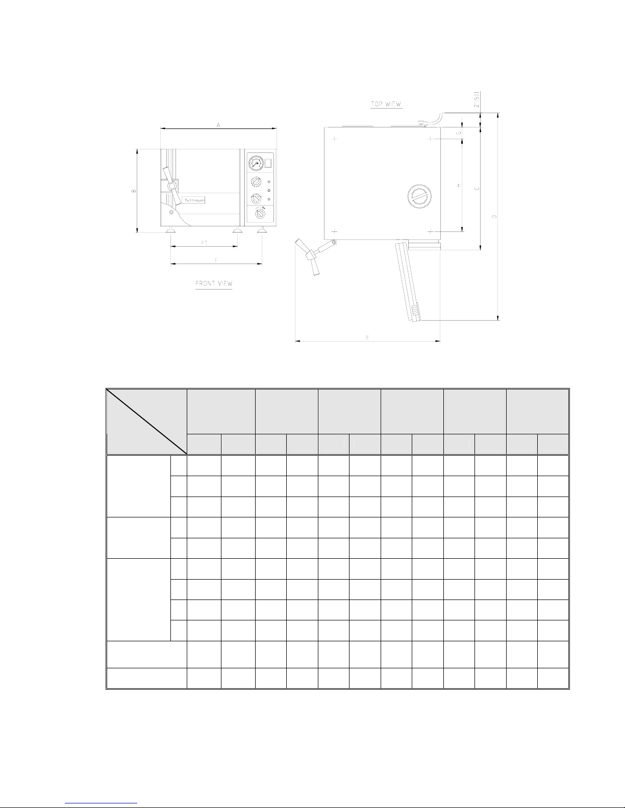
2.9 Dimensions
1730
M, MK
MK-Valueklave
2340
M, MK
2540
M, MK
3140
M
3850
M
3870
M
Model
Dimensions
in mm in mm in mm in mm in mm in mm
A 17.4 440 20.0 510 20.0 510 23.2 590 26.0 660 26.0 660
B 12.0 305 14.4 365 14.4 365 17.7 450 20.7 525 20.7 525
Overall
Dimensions
C 17.9 455 21.5 545 21.5 545 21.9 556 27.5 695 34.5 875
D 29.5 750 35.8 910 35.8 910 39.0 990 45.5 1155 53.0 1335
Maximum
dimensions
(door open)
E 22.0 560 25.8 655 25.8 655 29.7 755 32.0 815 32.0 815
F1 13.7 347 11.8 299 11.8 299 19.2 488 17.7 450 17.7 450
F 13.4 339 16.6 422 16.6 422 14.6 371 22.2 564 22.2 564
G 2.0 50 2.0 50 2.0 50 2.0 50 2.0 50 2.0 50
Distance
between
supporting
legs
F1-front legs
F -rear legs
H 12.4 315 15.8 400 15.8 400 15.2 386 21.8 555 30.5 725
Chamber
Diameter
6.7 170 9.1 230 10 254 12.3 312 15.1 384 15.1 384
Chamber Depth 13.4 340 18.5 470 18.7 475 15.4 391 22.8 580 29.9 760

9
Shipping
Volume
0.18 m
3
(6.35 cu.f.)
0.27m
3
(9.4 cu.f.)
0.27m
3
(9.4 cu. f.)
0.35 m
3
(12.4 cu.f)
0.63 m
3
(22.2cu.f.)
0.76m
3
(26.8cu.f)
Shipping
Weight
24.8 kgs.
(54.7 lbs.)
35.7 kgs.
(78.7 lbs.)
47.8 kgs.
(83.3 lbs.)
60 kgs
(132 lbs.)
89 kgs.
(196 lbs.)
102 kgs.
(225 lbs.)
full
2
3
4
10
15
No. of
standard
Cassettes
(Optional)
Half
2
2
3
4
No.
of trays
3
3
4
2
2
2
Tray dimensions
W X D X H
12 x 29.5 x 2 cm
(4.7" x 11.6" x 0.8")
17 x 41.5 x 2cm
(6.7" x 16.3" x 0.8")
17 x 41.5 x 2 cm
(6.7" x 16.3" x0.8")
25.6 x 40.8 x 2.5 cm
(10.1” x 16.1” x 1”)
19.8 x 40.8 x 2.5 cm
(7.8” x 16.1” x 1”)
28 x 50 x 2.5 cm
(11" x 20 " x 1" )
35 x 50 x 2.5cm
(14" x 20 " x 1")
28 x 67 x 2.5cm
( 11" x 26" x 1" )
35 x 67 x 2.5
(14" x 26" x 1")
Volume of
chamber
7.5 liters.
(2 US gal.)
19 liters.
(5 US gal.)
23 liters.
(6 US gal.)
34.4 liters
(7.8 US gal.)
65 liters.
(17US gal)
84 liters.
(22 US gal)
Chamber
dimensions
DIA x D
17 x 34 cm
(6.7" x 13.4")
23 x 47 cm
(9" x 18.5")
25.4 x 47.5cm
(10" x 18.7")
31.2 x 39.1
(12.3” x 15.4”)
38 × 58 cm.
(15" × 23" )
38x76 cm
(15" x 30")
2.10 Technical Specifications
Model
Specifications
1730 M, MK
MK-Valueklave
2340 M, MK
2540 M, MK
3140 M
3850 M
3870 M
10
2.11 Electrical Data
1730 2340 2540 3140 3850 3870
Model
Specifications
M
MK
MK-V
M MK M MK M M M
Total power
model 120V
8.8A 11.2A 11.7A - 11.7A -
20.0
A
- -
Total power
model 230V
4.6A 5.9A 6.0A 9.6A 6.0A 9.6A
10.4A 10.4
A
13A
Heaters W 1050 1350 1400 2200 1400 2200 2400 2400 3000
Degree of protection by enclosure IP31
2.12 Maximum Load Sizes
Loads
Models
lbs kg
1730 3.3 1.5
2340 7.0 3.2
2540 8.8 4.0
3140 11.0 5.0
3850 13.6 6.0
3870 17.5 8.0
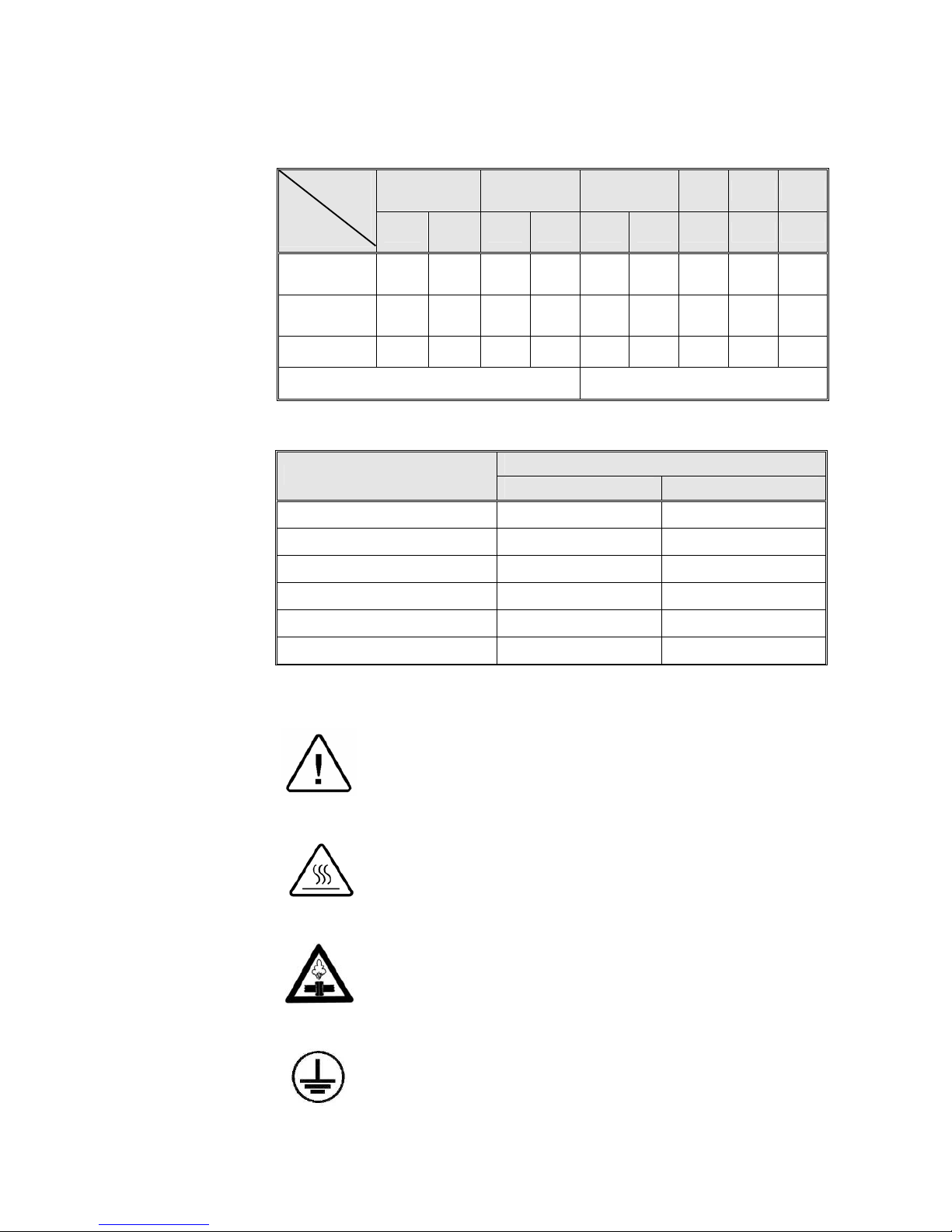
2.13 Symbol Description
Caution! Hot steam.
Caution! Consult accompanying documents
Caution! Hot Surface.
Ground
11
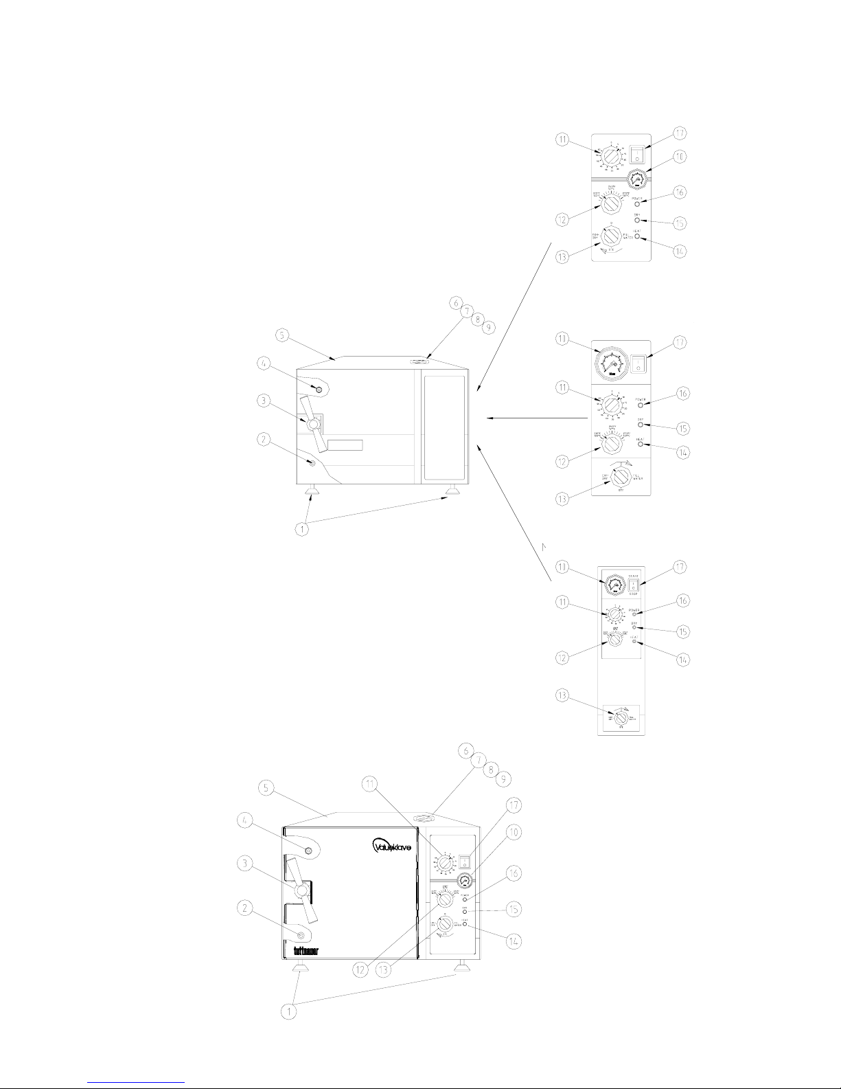
FRONT VIEW
1. Front legs 9. Air trap jet
2. Reservoir water drain 10. Pressure gauge
valve. 11. Timer
3. Door Closing Device 12. Thermostat (B10) knob
4. Door Micro-switch 13. Multipurpose valve
5. Autoclave cover 14. Heat indicator light
6. Water reservoir cover 15. Dry indicator light
7. Water reservoir 16. Power indicator light
8. Safety valve 17. Main power switch
Model 1730 MK Valuelave
Models 3140/3850/3870 M, MK
Models 2340/2540 M, MK
Models 1730 M, MK
12
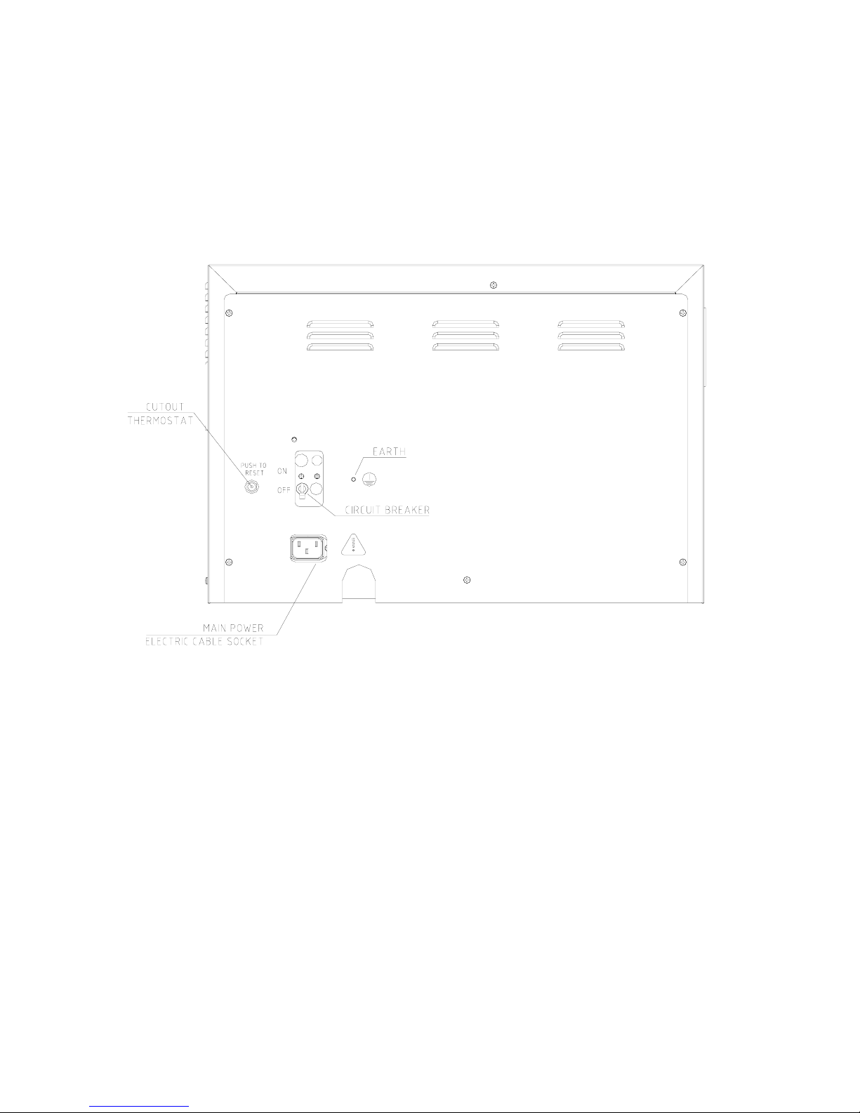
REAR VIEW
13
3 DESCRIPTION OF COMPONENTS
The item numbers refer to the front view in the previous page
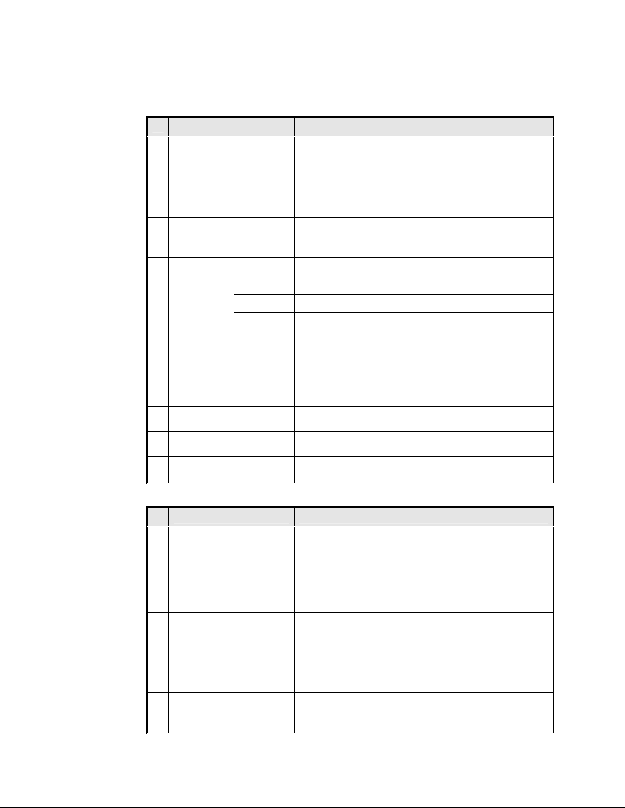
3.1 Control Panel
Item
Description Operation
10.
PRESSURE GAUGE
0-60 psi, (0-4bar) indicates the chamber pressure and
includes maximum point indicator.
11.
TIMER 0-60 min.
Sets the time for sterilization and drying cycles
(see section 7 for correct cycle time settings). Note:
The power to the heating elements is switched off
when the Timer reaches 0 minutes.
12.
THERMOSTAT
Sets the desired sterilization temperature for each
cycle within the range of 212ºF - 273ºF (100ºC 134ºC).”
Position
1. FILL
Water
flows from the water reservoir into the chamber.
2. STE.
Valve closed to all directions.
3. EXH.&
DRY
Exhausts the steam from the chamber into the water
reservoir after the sterilization cycle is finished.
13.
MULTIPURPOSE
VALVE
4. “ 0 ”
Heating elements are disconnected, no cycle is in
progress.
14.
HEAT INDICATOR
LIGHT
Lights to indicate that the heaters are activated. It will
cycle off and on when the temperature reaches the
preset valve.
15.
DRY INDICATOR
LIGHT
Lights to indicate that drying cycle is in process.
16.
POWER INDICATOR
LIGHT
Light to indicate that the main switch is on.
17.
MAIN SWITCH-
Main power switch, which supplies electric power to
the autoclave.
3.2 Other Components
Item
Description Operation
2.
WATER DRAIN VALVE
Enables the drainage of water from the reservoir.
7.
WATER RESERVOIR
Holds water for sterilization and also serves as a
condenser for the hot steam during the exhaust phase.
8.
SAFETY VALVE
Located in the water reservoir. Protects the chamber
by releasing any pressure above 40psi (2.7bar). This
Safety Valve is required and approved by ASME.
9.
AIR TRAP JET
Located in the water reservoir. Eliminates air during
heat up phase to insure correct sterilization
temperature is reached. Also prevents air pockets and
pockets of cold steam from forming in the chamber.
♦
SAFETY THERMOSTAT
Prevents over-heating during the sterilization and
drying stages, will automatically reset itself
♦
CUT-OUT
THERMOSTAT
Cuts off the power in case of overheating if the safety
thermostat does not operate. This thermostat does not
reconnect automatically but must be reset.
 Loading...