

M-D Pneumatics
Rotary Positive Displacement Transport Blower
WARNING: Do Not Operate Before Reading Manual
T855 / T1055
OPERATOR’S MANUAL
™
Manual 2023 Rev C p/n 2023
All rights reserved. Product information and specications subject to change.
Operator’s Manual: Tuthill T855/T1055 - Standard Weight Rotary Positive Displacement Transport Blower
Tuthill Vacuum & Blower Systems tuthillvacuumblower.com 800.825.6937
Copyright © 2018 Tuthill Vacuum & Blower Systems

The employees of Tuthill Vacuum & Blower Systems thank you for your purchase!
Tuthill Vacuum & Blower Systems proudly manufactures
Kinney® vacuum pumps and M-D PneumaticsTM blowers and
vacuum boosters in Springeld, Missouri, USA. We bring
100+ years of engineering experience and solid, handson care to help customers keep their processes running.
Your satisfaction is important to us so please take time to
provide your Tuthill sales representative with performance
feedback. We love to hear from our customers!
Tuthill is a family owned business that was started by James
B. Tuthill in 1892. At that time, Tuthill manufactured common brick to Chicago construction companies who were
fueling the city’s rapid expansion. Fast forward to today
and Tuthill now serves sustaining, global markets like agriculture, chemical, construction, energy, food and beverage,
pharmaceuticals and medical, transportation, and utilities.
While the company has changed in what it manufactures,
one thing remains throughout every Tuthill line of business
– we are a company with HEART. Our slogan is “Pump Your
Heart Into It” and everyday our employees do just that as
they represent the Tuthill brand and dare to make better.
A company with heart
right from the start.
Thank you for making Tuthill Vacuum & Blower Systems
part of your company’s process!
FIND OUT MORE AT
TUTHILL.COM
Disclaimer Statement:
All information, illustrations and specications in this manual are based on the latest information available at
the time of publishing. The illustrations used in this manual are intended as representative reference views only.
Products are under a continous improvement policy. Thus, information, illustrations and/or specications to
explain and or exemplify a product, service or maintenance improvement may be changed at any time without
notice.
Rights Reserved Statement:
No part of this publication may be reproduced or used in any form by any means - graphic, electronic or mechanical, including photocopying, recording, taping or information storage and retrieval systems - without the
written permission of Tuthill Vacuum & Blower Systems.
Copyright © 2018 Tuthill Vacuum & Blower Systems
All rights reserved. Product information and specications subject to change.

Table of Contents
Table of Contents
Introduction .................................................................................. 1
Safety ............................................................................................ 2
Graphic Conventions in this Manual ..................................................... 2
Safety Instructions................................................................................. 3
Safety Precautions ..................................................................... 3
Installation .................................................................................... 5
Safety Checklist .................................................................................... 5
Specifications ........................................................................................ 6
Outline Drawings ................................................................................... 7
T855 / T1055 Vent Holes ....................................................................... 8
PTO Selection for Transmission ............................................................. 9
Engine Speed ....................................................................................... 9
Pressure Relief Valve ............................................................................ 9
Air Filter ................................................................................................. 9
Suction and Discharge Piping .............................................................. 9
Mounting Bracket .................................................................................. 9
Check Valve .......................................................................................... 9
Mufflers and Discharge Filtration .......................................................... 9
Vacuum Valve ...................................................................................... 10
Operator’s Manual 2023 Rev C p/n 2023
i

Table of Contents
Operation .................................................................................... 22
Maintenance ............................................................................... 23
Assembly Drawing and Parts List ............................................ 24
Performance Curves ........................................................................... 12
Performance Curves (US) ........................................................ 12
Performance Curves (Metric) ................................................... 16
Lubrication .......................................................................................... 20
Filling Procedure ...................................................................... 20
Regular Maintenance .......................................................................... 23
Blower Service & Repair ..................................................................... 23
Assembly Drawing .............................................................................. 24
Parts List ............................................................................................. 25
Blower Installation Components ......................................................... 25
ii
Operator’s Manual 2023 Rev C p/n 2023

CONGRATULATIONS on the purchase of a new
Tuthill Transport Blower. Please examine the
blower for shipping damage, and if any damage
is found, report it immediately to the carrier. If
the blower is to be installed at a later date, make
sure it is stored in a clean, dry location and
rotated monthly. Make sure covers are kept on all
openings. If the blower is stored outdoors, be sure
to protect it from weather and corrosion.
Tuthill Transport Blowers are built to exacting
standards and, if properly installed and maintained,
will provide many years of reliable service. Read
and follow every step of these instructions when
installing and maintaining the blower.
OTE: N Record the blower model and serial
numbers of the machine in the
OPERATING DATA form on the inside
back cover of this manual. Use this
identication on any replacement part
orders, or if service or application
assistance is required.
01
INTRODUCTION
Operator’s Manual 2023 Rev C p/n 2023
1

02
SAFETY
GRAPHIC CONVENTIONS IN THIS
MANUAL
The following hazard levels are referenced within
this manual:
DANGER
!
Indicates a hazardous situation that, if not
avoided, will result in death or serious injury.
WARNING
!
Indicates a hazardous situation that, if not
avoided, could result in death or serious
injury.
CAUTION
!
OTE: N Indicates a procedure, practice, or
condition that should be followed in
order for the equipment to function in the
manner intended.
CAUTION
!
Read manual before operation
or bodily harm may result.
Attention should be given to the
safety related sections of this
manual.
Indicates a hazardous situation that, if not
avoided, could result in minor or moderate
injury.
Indicates a situation that can cause damage
to equipment, personal property, and/or
the environment or cause the equipment to
operate improperly.
2
Operator’s Manual 2023 Rev C p/n 2023

02
Safety
WARNING
Keep body and
clothing away from
machine openings.
WARNING
Keep body
and clothing away
from drive shaft.
SAFETY INSTRUCTIONS
1. Do not operate before reading the enclosed
instruction manual.
2. Use adequate protection, warning and safety
equipment necessary to protect against
hazards involved in installation and operation
of this equipment.
The above safety instruction tags were
attached to your unit prior to shipment. Do not
remove, paint over or obscure in any manner.
Failure to heed these warnings could result in
serious bodily injury to the personnel operating
and maintaining this equipment.
WARNING
!
• Keep hands and clothing away from
rotating machinery, inlet and discharge
openings.
• Blower and drive mounting bolts must be
secured.
• Drive belts and coupling guards must be
in place.
• Noise level may require ear protection.
• Blower heat can cause burns if touched.
WARNING
Hearing
Protection
Required
CAUTION
Do not
touch hot
surfaces.
Safety Precautions
For equipment covered specically or indirectly
in this operator’s manual, it is important that all
personnel observe safety precautions to minimize
the chances of injury. Among many considerations,
the following should particularly be noted:
• Rotating shafts can be dangerous. You can
snag clothes, skin, hair, hands, etc. This can
cause serious injury or death.
• Do not work under the vehicle while the engine
is running.
• Do not work on a shaft (with or without a guard)
while the engine is running.
• Do not engage or disengage driven equipment
by hand from under the vehicle while the engine
is running.
• In order to avoid becoming entangled, install the
power take off and/or shaft behind the frame rail,
tanks, battery box, etc.
• If power take off and/or shaft are still exposed
after installation, install a guard.
• Install a support strap when servicing a drive
shaft to prevent personal injury.
A SERIOUS OR FATAL INJURY CAN OCCUR:
• If you lack proper training
• If you fail to follow proper procedures
• If you do not use proper tools and safety
equipment
• If you assemble drive line components
improperly
• If you use incompatible drive line components
• If you use worn out or damaged drive line
components
• If you use drive line components in a
non‑approved application
Operator’s Manual 2023 Rev C p/n 2023
3

02
Safety
This manual contains safety instructions. Read,
understand and follow this manual.
• Get proper training
• Learn and follow safe operating procedures
• Use proper tools and safety equipment
• Use proper components in good condition
4
Operator’s Manual 2023 Rev C p/n 2023

INSTALLATION
SAFETY CHECKLIST
Complete this checklist before operating the
blower.
TRUCK NUMBER BLOWER MODEL NUMBER
GEARBOX NUMBER BLOWER SERIAL NUMBER
P.T.O. NUMBER DATE INSTALLED
P.T.O. RATIO INSPECTED BY
03
Is ratio and horsepower correct for PTO?
Mount PTO as per manufacturer’s
recommendations and rell transmission.
Ensure oil levels are at the center of the sight
glass when blower is not running.
Without drive line connected, can the blower be
rotated by hand?
Is the drive line installed at the correct angle and
phase with all fasteners secured?
Ensure PTO rotates blower in the correct
direction indicated by arrow.
Ensure air inlet lter is connected and located
away from truck exhaust.
Remove Camlock dust cap, and discharge
piping open to atmosphere.
With tractor engine at idle, slowly engage PTO.
Check for correct rotation.
Slowly bring blower up to operating speed.
Check for vibration, mechanical noise, oil leaks
and mounting integrity.
Stop blower, connect blower discharge hose to
trailer, and run blower at operating pressure of
trailer for 15 minutes at normal speed.
Does relief valve allow 15 psig (1 bar g)
pressure for safety of trailer?
Does engine maintain correct RPM throughout
test?
Shut down machine. Check Shur-Melt
relief valve, lter, piping, and oil sumps for
integrity.
Is correct engine speed label visible in cab?
®
plugs,
Operator’s Manual 2023 Rev C p/n 2023
5
03
Installation
SPECIFICATIONS
WARNING
!
The blower and accessories will
become hot enough to cause serious
skin burns on contact.
Rotating machinery is dangerous.
Always wear ear protection when
near an operating blower.
MODEL AIR FLOW RANGE
T855 250 – 1,000 CFM
(527 – 2,888 m³/h)
T1055 450 – 1,300 CFM
(764 – 2,209 m³/h)
OTE: N Reduce the maximum operating pressure by 1 psi (0.068 bar) for each 2,000 feet (610 m) of
elevation above sea level.
Example: At an altitude of 4,000 feet (1,219 m), the maximum working pressure of the blower will
decrease by 2 psi (0.137 bar).
Table 3-1 – Specifications
MAXIMUM
PRESSURE
20 psig
(1.37 bar g)
18 psig
(1.24 bar g)
MAXIMUM
VACUUM
17 inch-Hg
(575 Mbar)
17 inch-Hg
(575 Mbar)
RPM RANGE
1,000 – 3,000
1,450 – 3,000
6
Operator’s Manual 2023 Rev C p/n 2023

OUTLINE DRAWINGS
Dimensions shown are not on a controlled
document and as such are subject to change.
Certied drawings are available through your local
Tuthill Transport Blower Distributor. Dimensions
are shown in inches and millimeters.
03
Installation
Figure 3-1 – Outline Drawings
Operator’s Manual 2023 Rev C p/n 2023
7
03
Installation
T855 / T1055 VENT HOLES
OTE: N Due to multiple bracket congurations
that are used by installers across the
country our T855 and T1055 blowers have
1/8" threaded NPT vent holes. Vent plugs
are not supplied with the blower.
If you choose to place plugs into vent holes to keep
foreign matter out of the units, you can purchase
HK 1/8-27 NPTF 7/8 Taper Flush Socket Pressure
Plug part # 1181142 from Fastenal or similar style
plugs from your local auto parts store. Another
option, depending on mounting bracket space, is
to use 90° elbows with or without exible tubing.
If you choose to use vent plugs, then follow the
subsequent instructions. The exact plug location
will vary based on the mounting position.
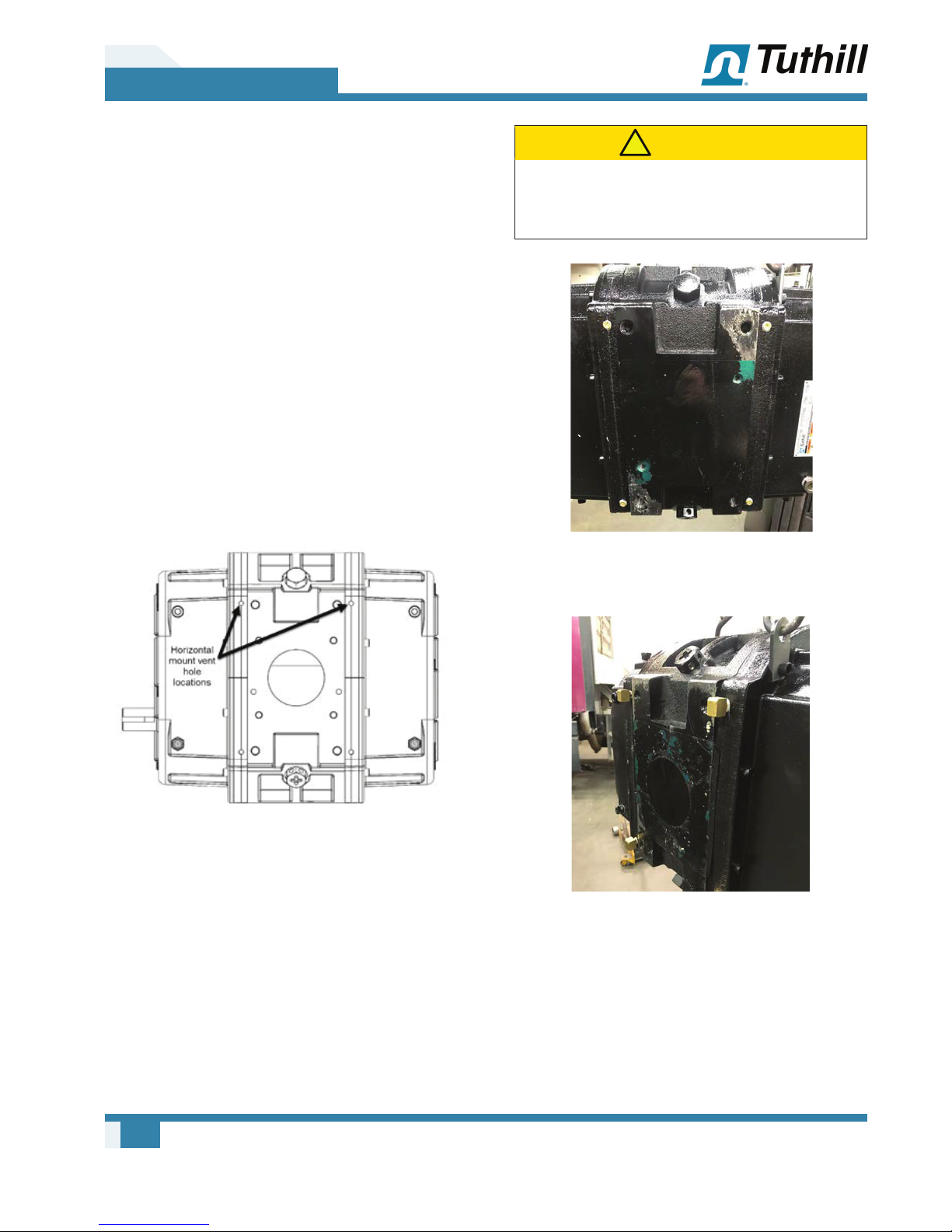
The image below shows one option for the vent
hole locations on a horizontal airow mount.
CAUTION
!
Never plug all the vent holes or serious damage to
seals and bearings will result. Four vent holes (two
per side or all four on one side) must always be open.
Figure 3-3 – Alternate plug configuration: Horizontal
mount with holes plugged on the bracket side
Figure 3-2 – Mounting Configuration
In this mounting conguration (See Figure 3-2)
the four holes (two are shown and two are on the
opposite side top) could have plugs added to them.
This would leave the four holes on the bottom of
the unit open or 90° 1/8" NPT elbows that face
down.
Four vent holes should always be open to air. You
can plug all the holes on the bracket side, then use
four 90° elbows on the non-bracket side (horizontal
mount). Or you can plug two on each end plate at
the top side and leave two on each end plate at the
bottom open.
8
Figure 3-4 – Alternate plug configuration: Horizontal
mount with street elbows
Operator’s Manual 2023 Rev C p/n 2023

PTO SELECTION FOR
03
Installation
TRANSMISSION
Blower speed and pressure require adequate
horsepower and torque. See Performance Curves
on page 12.
Engine speed and blower speed require the
adequate ratio PTO be installed for proper blower
operation.
ENGINE SPEED
Keep engine speed constant when the blower is
in the operating cycle. Install a constant-speed
governor or throttle control system to ensure
proper blower operation.
PRESSURE RELIEF VALVE
Size the pressure relief valve for the correct air ow
and pressure rating. Install the valve as close to
the blower as possible and before the check valve.
An undersized air lter will cause the blower
to operate at higher temperatures. This can
cause blower to overheat, causing irreparable
damage.
SUCTION AND DISCHARGE PIPING
All piping should be free and clear of any welding
slag or foreign material.
The suction piping requirement is a minimum of
5 in. (127 mm) diameter for proper ow to the
blower.
Discharge piping is a minimum of 4 in. (102 mm)
diameter.
Do not use a rubber elbow in the suction line
during vacuum operation. The elbow will fail
causing the blower to overheat. This will cause
damage to the blower.
Ensure that pipe compound is used on the threads
of the male end of the relief valve to seal against
air leakage.
An undersized or improperly set relief valve
will cause the blower to operate at higher
temperatures. This can cause the blower to
overheat, causing irreparable damage.
AIR FILTER
Select a lter suitable for the air ow requirement
of the application. Use air lters on food and plastic
products to prevent contamination.
MOUNTING BRACKET
To reduce stress on the blower housing, be sure to
properly mount the blower with the correct bracket.
CHECK VALVE
Minimum restriction for application. Mount
downstream of the relief valve. Size the valve for
maximum air ow (CFM or m³/hr).
MUFFLERS AND DISCHARGE
FILTRATION
Minimum restriction for application. Mount
downstream of the relief valve.
Operator’s Manual 2023 Rev C p/n 2023
9

03
Installation
VACUUM VALVE
Size for proper air ow and vacuum rating.
This valve should be located before the blower
inlet lter. This valve is normally mounted on the
trailer.
To properly protect the blower from
overheating when vacuum loading, install a
vacuum valve.
RIGHT DRIVE CCW ROTATION LEFT DRIVE CW ROTATION
Figure 3-5 – Flow Direction and Rotation
10
Operator’s Manual 2023 Rev C p/n 2023

03
Installation
This page intentionally blank
Operator’s Manual 2023 Rev C p/n 2023
11

03
T850 / T855 PRESSURE CURVE
Airflow at Inlet (CFM)
1000
BHP
Installation
PERFORMANCE CURVES
PERFORMANCE CURVES (US)
900
800
700
600
500
400
300
200
AIRFLOW BASED UPON INLET
CONDITIONS OF: 14.7 PSIA & 70° F
# PSIG DISCHARGE PRESSURE
1000 15002000
2500 3000
2
5
8
12
15
18
20
PSIG
PSIG
20
18
15
12
8
5
2
100
75
50
25
0
RPM
Figure 3-6 – T850 / T855 Pressure Curve (US)
12
Operator’s Manual 2023 Rev C p/n 2023

03
T850 / T855 VACUUM CURVE
Airflow at Inlet (CFM)
1000
BHP
Installation
900
800
700
600
500
400
300
200
AIRFLOW BASED UPON
INLET: 70° F
DISCHARGE: 29.92" Hg Abs
1000 1500 2000
2
6
10
14
17
In. Hg
In. Hg
17
14
10
6
2
2500 3000
100
75
50
25
0
RPM
Figure 3-7 – T850 / T855 Vacuum Curve (US)
Operator’s Manual 2023 Rev C p/n 2023
13

03
T1050 / T1055 PRESSURE CURVE
Airflow at Inlet (CFM)
P
Installation
1350
1200
1050
900
750
600
450
300
150
AIRFLOW BASED UPON INLET
CONDITIONS OF:
# PSIG DISCHARGE PRESSURE
14.7 PSIA & 70° F
0
2
5
8
10
12
15
18
PSIG
PSIG
18
15
12
10
8
5
2
BH
120
105
90
75
60
45
30
15
0
10001500 2000
Figure 3-8 – T1050 / T1055 Pressure Curve (US)
2500 3000
14
Operator’s Manual 2023 Rev C p/n 2023

03
T1050 / T1055 VACUUM CURVE
Airflow at Inlet (CFM)
Installation
1350
1200
1050
900
750
600
450
300
150
AIRFLOW BASED UPON
INLET: 70° F
DISCHARGE: 29.92" Hg Abs
0
2
5
8
10
12
16
17
In. Hg
In. Hg
17
16
12
10
8
5
2
BHP
60
50
40
30
20
10
0
1000 1500 2000
Figure 3-9 – T1050 / T1055 Vacuum Curve (US)
2500 3000
Operator’s Manual 2023 Rev C p/n 2023
15
03
Installation
PERFORMANCE CURVES (METRIC)
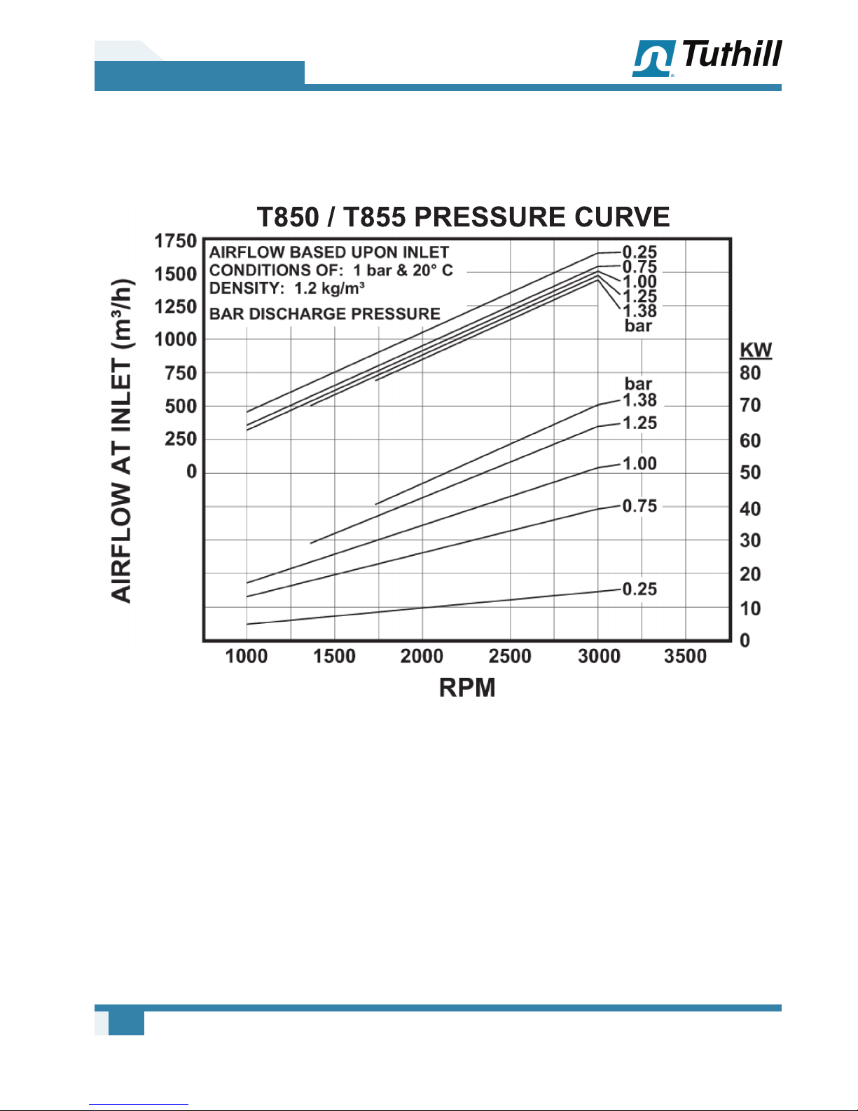
Figure 3-10 – T850 / T855 Pressure Curve (Metric)
16
Operator’s Manual 2023 Rev C p/n 2023
03
Installation
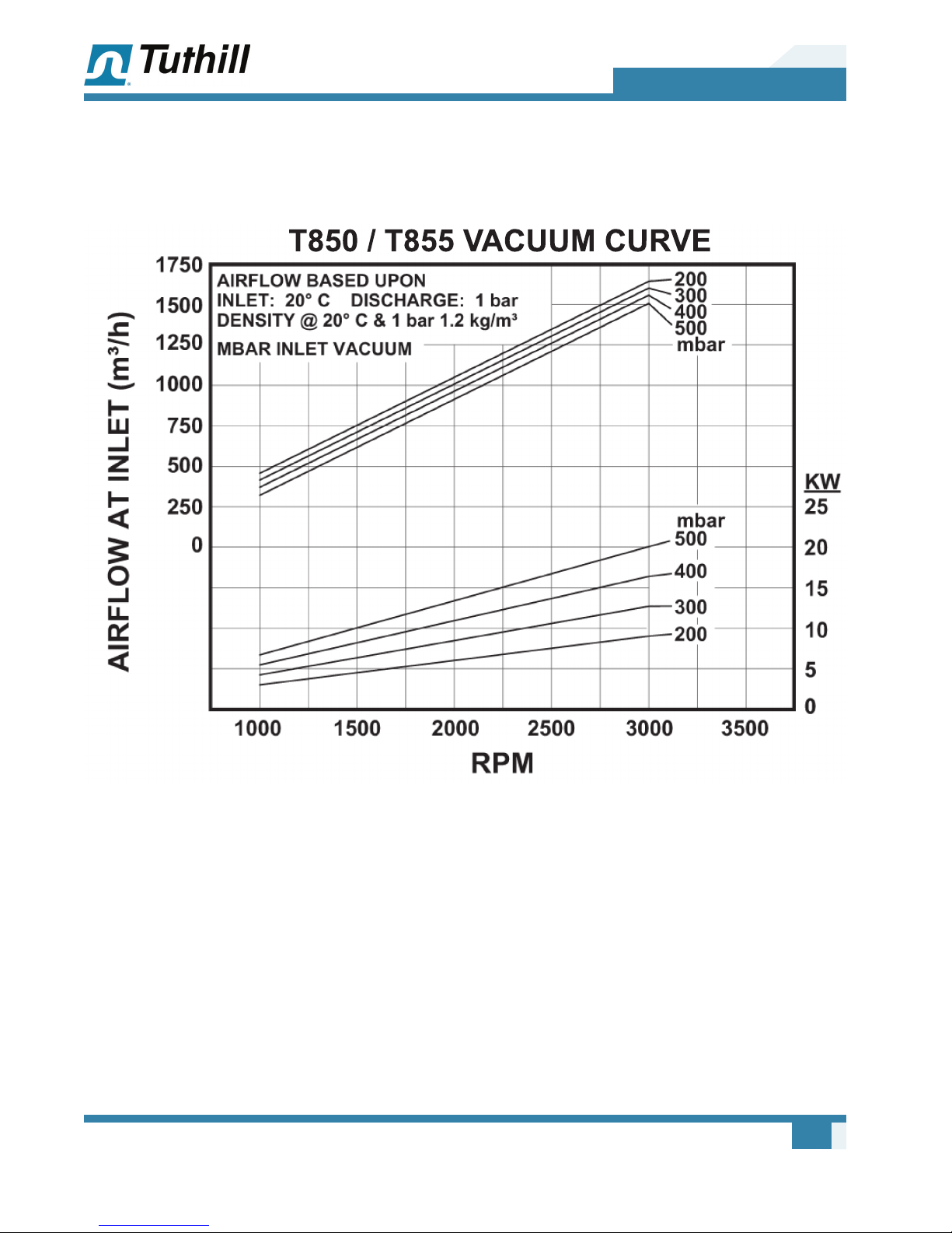
Figure 3-11 – T850 / T855 Vacuum Curve (Metric)
Operator’s Manual 2023 Rev C p/n 2023
17

03
Installation
Figure 3-12 – T1050 / T1055 Pressure Curve (Metric)
18
Operator’s Manual 2023 Rev C p/n 2023

03
Installation
Figure 3-13 – T1050 / T1055 Vacuum Curve (Metric)
Operator’s Manual 2023 Rev C p/n 2023
19

03
Installation
LUBRICATION
Every Tuthill blower is factory-tested, oil-drained,
and shipped dry. Fill both oil reservoirs to the
proper level before operation.
Every Tuthill Transport Blower is supplied with four
1-quart containers of Tuthill PneuLube™ ISO 100
synthetic oil. Before lling the blower, check Table
3-2 to conrm the amount of oil required.
For applications requiring food-grade lubricant, use
only Tuthill PneuLube FG synthetic oil.
OTE: N If installing a Tuthill Transport Blower
for vertical air ow (optional), additional
oil than what is included with the
blower will be needed for installation.
Tuthill PneuLube is available from your
authorized Tuthill Transport Blower
Distributor.
Filling Procedure
To ensure the proper oil level, always use this lling
procedure:
1. Remove the ll plugs from both gear end and
drive end plates.
2. Slowly pour oil through ll until oil appears in
the oil sight glass. Bring the oil level to the
center of the sight glass.
CAUTION
!
Do not start the blower until you are certain that oil
is in BOTH ends of the blower. Check BOTH sight
glasses to ensure that oil levels are correct before
starting. Operation of the blower without proper
lubrication will cause the blower to fail and void its
warranty.
WARNING
!
NEVER ATTEMPT TO CHANGE OIL WHILE THE BLOWER
IS IN OPERATION. Failure to heed this warning
will result in damage to equipment and/or serious
personal injury. Oil level must be checked while the
blower is not running and truck is parked on a level
surface.
SHUR-MELT™ Thermal Relief Plugs
All T855 and T1055 blowers are equipped with two
patented thermal relief plugs. Upon temperature
activation, the plugs will relieve 5 to 6 PSIG to
protect the blower from damage. When replacing
these plugs, you must ensure that a plug is
installed on each end of the blower for complete
protection.
3. Verify the oil level is at the proper level in both
the gear end and drive end sight glasses.
4. Replace the ll plugs that were removed in
step 1.
Never mix oil types or grades in a Tuthill
Transport Blower. Mixing lubricants in the
blower will result in gear and bearing failure.
20
Operator’s Manual 2023 Rev C p/n 2023

03
Installation
** If installing a T855 blower for vertical air ow (optional), additional oil than what is included with the blower
will be needed for installation. Tuthill PneuLube is available from your authorized Tuthill Transport Blower
Distributor.
Figure 3-14 – Oil Fill Locations
HORIZONTAL AIR FLOW
(STANDARD)
Drive end 1.06 qt (1.0 L) (34 oz) 1.68 qt (1.59 L) (54 oz)
Non-drive (gear) end 1.0 qt (0.95 L) (32 oz) 1.75 qt (1.66 L) (56 oz)
Table 3-2 – Lubrication Capacities
OTE: N Oil capacities are based on lling from
dry condition. Less oil may be needed
depending on emptiness of oil reservoirs
after draining.
VERTICAL AIR FLOW
(OPTIONAL)
Operator’s Manual 2023 Rev C p/n 2023
21

04
OPERATION
1. Inspect the blower mounting, drive line, PTO,
and air lter for damage.
2. Remove the Camlock dust cap and connect
the hot air hose.
3. Follow the trailer instructions regarding product
hose connection and valve operation.
4. Slowly engage PTO with the engine at idle,
bring it up to operating speed, and lock the
engine at the recommended speed (shown in
the cab).
5. Unload the trailer as per trailer manufacturer’s
recommendation. Do not exceed the maximum
tank pressure.
6. While discharging, visually check the blower
for vibration, mechanical noise or excessive
heat.
7. If the relief valve is opening, adjust the
proportioning valve to reduce the tank
pressure.
OPERATION
WARNING
!
The blower and accessories will
become hot enough to cause
serious skin burns on contact.
Rotating machinery is
dangerous.
Always wear ear protection
when near an operating blower.
Do not run at slower RPM to cool unit down.
Slower RPM will produce heat.
8. Reduce pressure to zero as per the trailer
manufacturer’s instructions.
9. Disengage PTO. No cool-down period is
required.
10. Disconnect the blower hose and replace the
Camlock dust cap.
22
Operator’s Manual 2023 Rev C p/n 2023

REGULAR MAINTENANCE
A well-designed maintenance program will add
years of service to the blower.
Check a newly installed blower frequently during
the rst month of operation, especially lubrication.
Check the oil level and add oil as needed.
Complete oil changes are recommended annually,
or more frequently depending on the operating
conditions. The following is recommended as a
minimum maintenance program. An oil analysis
program is recommended.
DAILY WEEKLY MONTHLY SEMIANNUALLY ANNUALLY
05
MAINTENANCE
MAINTENANCE
1. Check and
maintain oil
level, and
add oil as
necessary.
2. Check air lter
restriction
indicator.
1. Clean the air
lter. A clogged
air lter can
seriously affect
the efciency
of the blower
and cause
overheating and
oil usage.
2. Check the
relief valve to
make sure it
is operating
properly.
1. Inspect the
2. Inspect the
BLOWER SERVICE & REPAIR
Tuthill transport blowers are manufactured and
assembled to exacting standards to assure
optimum performance and longevity. Tuthill
Operator’s Manual 2023 Rev C p/n 2023
entire system
for leaks.
condition of the
oil and change
if necessary.
recommends that only factory trained technicians
perform major overhauls on its transport blowers.
Contact Tuthill direct for the location of trained
distributors or to schedule a repair at our factory
repair center.
1. Inspect the
drive line
bearings.
1. Change the oil
annually.
23
06
ASSEMBLY DRAWING AND PARTS LIST
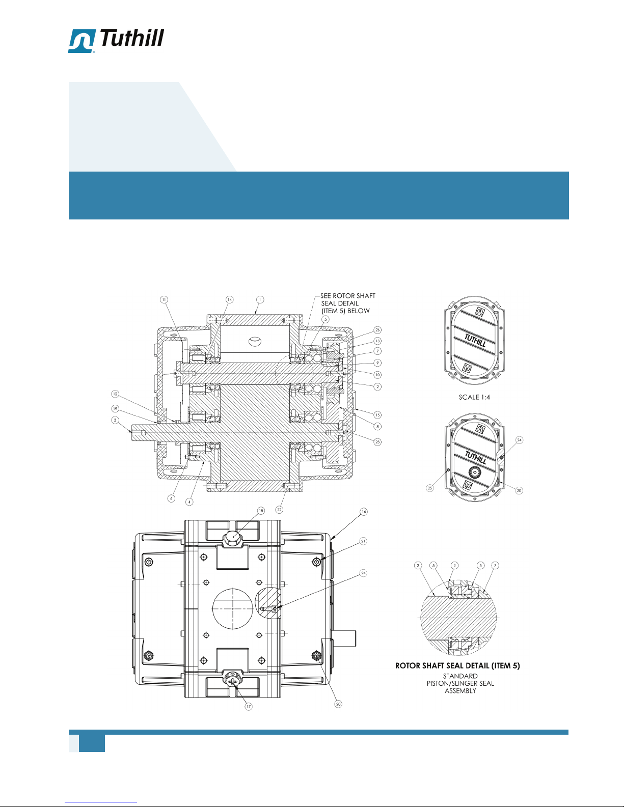
ASSEMBLY DRAWING
24
Operator’s Manual 2023 Rev C p/n 2023

PARTS LIST
06
Assembly Drawing and Parts List
ITEM
NO.
1 Housing 1
2 Driven Rotor 1
3 Drive Rotor 1
4 End Plate 2
5 Piston/Slinger Seal Assembly 4
6 Bearing 2
7 Bearings 2
8 Timing Gear Assembly 1 Set
9 Gear Key 2
10 Washer Rotor 3
11 Oil Slinger Driven Assembly 1
12 Oil Slinger Drive Assembly 1
13 Bearing Retainer 2
14 Bearing Shims 4
15 Gear End Cover 1
16 Drive End Cover 1
17 Shur-Melt Plug™ (LH Thread) 2
18 Plug Transport Blower 2
19 Drive Shaft Seal 1
20 Oil Sight Glass 4
21 Pipe Plug 12
22 Dowel Pins 6
23 Socket Head Cap Screw 3
24 Socket Head Cap Screw 20
25 Socket Head Cap Screw 16
26 Socket Head Cap Screw 8
PART DESCRIPTION STD
61580 Service Kit for T855 / T1055
PART # PART DESCRIPTION
6044 SHIM, ADJUSTABLE 1
61518
30238-5310 BEARING, BALL, 2 ROW 2
30410-2310
17024-25
18131-6
16924
61047-050 BREATHER, 1/2” NPT 2
17024-3
17024-4
17024-5
61307 KEY, GEAR TIMING 2
61484 Service Kit for T850 / T1050
PART # PART DESCRIPTION QTY
ALL PARTS LISTED ABOVE FOR 61580
SERVICE KIT ARE INCLUDED, AS WELL AS
THE FOLLOWING:
61287 GASKET, T850 2
GASKET, PORT, T850/
T1050, NA1100
BEARING, ROLL
CYCLINDER, T850
--SHIM, BEARING, 2.000
ID X 0.025 THICK
SEAL ASSEMBLY PISTON
RING/LIP, VINTON
SEAL, TRIPLE LIP, VITON,
1.875 I.D.
--SHIM, BEARING, 2.000
ID X 0.003 THICK
--SHIM, BEARING, 2.000
ID X 0.004 THICK
--SHIM, BEARING, 2.000
ID X 0.005 THICK
QTY
2
2
2
4
1
2
4
2
Operator’s Manual 2023 Rev C p/n 2023
25


WARRANTY – TRANSPORT BLOWERS
Subject to the terms and conditions hereinafter set forth and set forth in General Terms of Sale, Tuthill Vacuum & Blower
Systems (the Seller) warrants products and parts of its manufacture, when shipped, and its work (including installation and
startup) when performed, will be of good quality and will be free from defects in material and workmanship. This warranty
applies only to Seller’s equipment, under use and service in accordance with Seller’s written instructions, recommendations
and ratings for installation, operating, maintenance and service of products, for a period as stated in the table below. Because
of varying conditions of installation and operation, all guarantees of performance are subject to plus or minus 5% variation.
(Non-standard materials are subject to a plus or minus 10% variation)
PRODUCT
TYPE
New 18 months from date of shipment, or 12 months after initial startup date, whichever occurs first
Remanufactured 12 months from date of shipment, or 12 months after initial startup date, whichever occurs first
Repair 12 months from date of shipment, or remaining warranty period, whichever is greater
WARRANTY DURATION
THIS WARRANTY EXTENDS ONLY TO BUYER AND/OR ORIGINAL END USER, AND IN NO EVENT SHALL THE SELLER
BE LIABLE FOR PROPERTY DAMAGE SUSTAINED BY A PERSON DESIGNATED BY THE LAW OF ANY JURISDICTION
AS A THIRD PARTY BENEFICIARY OF THIS WARRANTY OR ANY OTHER WARRANTY HELD TO SURVIVE SELLER’S
DISCLAIMER.
All accessories furnished by Seller but manufactured by others bear only that manufacturer’s standard warranty.
All claims for defective products, parts, or work under this warranty must be made in writing immediately upon discovery and,
in any event within one (1) year from date of shipment of the applicable item and all claims for defective work must be made
in writing immediately upon discovery and in any event within one (1) year from date of completion thereof by Seller. Unless
done with prior written consent of Seller, any repairs, alterations or disassembly of Seller’s equipment shall void warranty.
Installation and transportation costs are not included and defective items must be held for Seller’s inspection and returned to
Seller’s Ex-works point upon request.
THERE ARE NO WARRANTIES, EXPRESSED, IMPLIED OR STATUTORY WHICH EXTEND BEYOND THE DESCRIPTION
ON THE FACE HEREOF, INCLUDING WITHOUT LIMITATION, THE IMPLIED WARRANTIES OF MERCHANTABILITY AND
FITNESS OF PURPOSE.
After Buyer’s submission of a claim as provided above and its approval, Seller shall at its option either repair or replace its
product, part, or work at the original Ex-works point of shipment, or refund an equitable portion of the purchase price.
The products and parts sold hereunder are not warranted for operation with erosive or corrosive material or those which may
lead to build up of material within the product supplied, nor those which are incompatible with the materials of construction.
The Buyer shall have no claim whatsoever and no product or part shall be deemed to be defective by reason of failure to
resist erosive or corrosive action nor for problems resulting from build-up of material within the unit nor for problems due to
incompatibility with the materials of construction.
Any improper use, operation beyond capacity, substitution of parts not approved by Seller, or any alteration or repair by
others in such manner as in Seller’s judgment affects the product materially and adversely shall void this warranty.
No employee or representative of Seller other than an Officer of the Company is authorized to change this warranty in any
way or grant any other warranty. Any such change by an Officer of the Company must be in writing.
The foregoing is Seller’s only obligation and Buyer’s only remedy for breach of warranty, and except for gross negligence,
willful misconduct and remedies permitted under the General Terms of Sale in the sections on CONTRACT PERFORMANCE,
INSPECTION AND ACCEPTANCE and the PATENTS Clause hereof, the foregoing is BUYER’S ONLY REMEDY
HEREUNDER BY WAY OF BREACH OF CONTRACT, TORT OR OTHERWISE, WITHOUT REGARD TO WHETHER ANY
DEFECT WAS DISCOVERED OR LATENT AT THE TIME OF DELIVERY OF THE PRODUCT OR WORK. In no event shall
Buyer be entitled to incidental or consequential damages. Any action for breach of this agreement must commence within
one (1) year after the cause of action has occurred.
January 2005


OPERATING DATA FORM / PRODUCT REGISTRATION
It is to the user’s advantage to have the requested data filled in below and available in the event a problem should develop
in the blower or the system. This information is also helpful when ordering spare parts.
Model No. V-Belt Size Length
Serial No. Type of Lubrication
Start-up Date
Pump RPM Operating Vacuum
Pump Sheave
Diameter Any Other Special Accessories Supplied or in Use:
Motor Sheave
Diameter
Motor RPM HP
PTO
Manufacturer
PTO Model
PTO Ratio
NOTES:
IMPORTANT
All blowers manufactured by Tuthill Vacuum & Blower Systems are date-coded at time of shipment. In order
to assure you of the full benefits of the product warranty, please complete, tear out and return the product
registration card, or register online at tuthillvacuumblower.com.

Technical Support: 1-877-955-TECH (8324)
Service & Repair or Product Sales:
Tuthill Vacuum & Blower Systems
4840 West Kearney Street
Springeld, Missouri USA 65803-8702
O 417.865.8715 800.825.6937
F 417.865.2950
tuthillvacuumblower.com
All rights reserved. Product information and specications subject to change.
Manual 2023 Rev C p/n 2023
Copyright © 2018 Tuthill Vacuum & Blower Systems
T
S
I
G
E
R
VACUUM & BLOWER SYSTEMS
TUTHILL CORPORATION
I
N
T
E
R
N
A
T
I
O
N
A
L
Q
U
E
R
E
D
D
R
A
D
N
A
T
S
Y
T
I
L
A
04/18
 Loading...