


M-D Pneumatics
™
Mechanical Vacuum Boosters
Manual 2000 0811 ENG
WARNING: Do Not Operate Before Reading Manual
Mechanical C-Flange Vacuum Boosters
OPERATOR’S MANUAL
Models
3204 4009 5509 5518 7013 7026
3206 4012 5511 5524 7017
3210 5507 5514 7010 7021
91/93 Series - Horizontal Flow
90/92 Series - Vertical Flow
Operator’s Manual: Tuthill Mechanical C-Flange Vacuum Boosters
Tuthill Vacuum & Blower Systems tuthillvacuumblower.com 800.825.6937

TABLE OF CONTENTS
SECTION PAGE
1. INTRODUCTION 3
1.1 APPLICABLE DOCUMENTATION 3
1.2 SCOPE OF MANUAL 3
2. CONVENTIONS AND DATA PLATE 4
2.1 GRAPHIC CONVENTIONS IN MANUAL 4
2.2 DATA PLATE 4
3. LIFTING 5
4. DESCRIPTION 5
4.1 FLOW BY DIRECTION AND ROTATION 6
4.2 SPECIFICATIONS 7
5. INSTALLATION 8
5.1 GENERAL 8
5.1.1 LOCATION 10
5.1.2 FOUNDATION 10
5.1.3 BOOSTER AIR INTAKE 10
5.1.4 SOFT FOOT 11
5.2 SAFETY 11
5.3 LUBRICATION 12
5.3.1 FILLING PROCEDURE 13
5.3.2 FREQUENTLY ASKED QUESTIONS REGARDING LUBRICATION 13
5.3.3 HAZARDS ASSOCIATED WITH BREAKDOWN OR IGNITION OF LUBRICATION 14
5.4 PIPING CONNECTIONS 14
5.4.1 BLOCKAGE OR RESTRICTION 15
5.5 WATER COOLING INSTRUCTIONS 15
5.6 COOLING WATER CONNECTIONS 16
5.7 COOLING WATER SPECIFICATIONS 16
5.8 DRIVE COMPONENTS 16
5.9 MOTOR DRIVE 16
5.9.1 DIRECT COUPLED 16
5.10 MOTOR AND ELECTRICAL CONNECTIONS 17
5.11 C-FLANGE COUPLING INSTALLATION 17
5.11.1 WOOD’S COUPLINGS 17
5.11.2 LOVEJOY COUPLINGS 17
6. OPERATION 18
6.1 GENERAL 18
6.2 START-UP CHECKLIST 19
6.3 STARTING 19
6.4 OPERATING 19
6.5 STOPPING 20
6.6 STOPPING 20
6.7 WATER INJECTED VACUUM BOOSTERS 20
6.7.1 OPERATION 21
6.7.2 SHUTDOWN 21
6.8 RECOMMENDED SHUTDOWN PROCEDURE TO MINIMIZE RISK OF FREEZING OR CORROSION 22
7. MAINTENANCE 22
7.1 GENERAL 22
7.2 REGULAR MAINTENANCE 23
7.3 SPARE PARTS 23
7.4 FACTORY SERVICE & REPAIR 24
7.5 LONG TERM STORAGE 24
8. MODEL 3200C SERIES DISASSEMBLY AND REASSEMBLY 25
9. MODEL 4000C AND 5500C SERIES DISASSEMBLY AND REASSEMBLY 30
10. MODEL 7000C SERIES DISASSEMBLY AND REASSEMBLY 35
11. TROUBLESHOOTING 40
12. ASSEMBLY CLEARANCES 41
13. TORQUE CHART 41
14. RECOMMENDED LUBRICANTS 42
15. TOOL DRAWINGS 44
16. PARTS LISTS AND ASSEMBLY DRAWINGS 46
17. DECLARATION OF CONFORMITY 69
18. WARRANTY — BLOWER PRODUCTS 70
19. OPERATING DATA FORM / PRODUCT REGISTRATION 71
2

1. INTRODUCTION
CONGRATULATIONS on your purchase of a new C-Flange
Mechanical Vacuum Booster from Tuthill Vacuum & Blower
Systems. Please examine the booster for shipping damage,
and if any damage is found, report it immediately to the carrier.
If the booster is to be installed at a later date make sure it is
stored in a clean, dry location and rotated regularly. Make sure
covers are kept on all openings. If booster is stored outdoors
be sure to protect it from weather and corrosion.
This manual covers the installation, operation and maintenance
of 3200, 4000, 5500 and 7000 Series C-Flange mechanical
vacuum boosters. The boosters are manufactured for either a
vertical ow or a horizontal ow. Most in-eld drive conversions
MODEL
3200C
4000C
5500C
7000C
(1) Interconnecting cooling water between drive
shaft bearing housing and the two oil reservoirs.
Mechanical seals are used throughout.
(2) Water cooled only at drive shaft bearing
housing. Rotor seals are slinger type and a mechanical seal on the drive shaft.
MECHANICAL
SEAL
(1)
90/91
can be readily accomplished by changing the location of a few
external parts.
Mechanical Vacuum Boosters are built to exacting standards and if properly installed and maintained
will provide many years of reliable service. We urge you to take time to read and follow every step of these
instructions when installing and maintaining your booster. We have tried to make these instructions as
straightforward as possible. We realize getting any new piece of equipment up and running in as little time
as possible is imperative to production.
SLINGER
SEAL
(2)
92/93
NOTE
Record the blower model and serial numbers of your machine in the
OPERATING DATA form on the inside back cover of this manual. You will
1.1 APPLICABLE DOCUMENTATION
The applicable documents associated with this manual are:
• 2006/42/CE – Machinery Directive
• EN 1012-2:1996 – Compressors and vacuum pumps - Safety Requirements - Part 2: Vacuum Pumps
1.2 SCOPE OF MANUAL
The scope of this manual and the Declaration of Conformity includes the following components offered, as
a complete assembly, by Tuthill Vacuum & Blower Systems:
• Vacuum booster with integral C-face ange
• Coupling
• Motor adaptor kit
• Motor (optional)
save time and expense by including this reference identication on any
replacement part orders, or if you require service or application assistance.
3

2. CONVENTIONS AND DATA PLATE
http://www.tuthill.com
q
ASU eht ni edaM7396-528 )008(
g
REBMUN LAIRESREBMUN LEDOM
YEARMAWP
2.1 GRAPHIC CONVENTIONS IN MANUAL
This manual is the result of a risk assessment according the applicable documents referenced in section
1.1. The following are hazard levels are referenced within this manual:
DANGER
Indicates an immediate hazardous situation which, if not avoided, will result
in death or serious injury.
WARNING
Indicates that a physical injury or damage to health or property, if not
avoided, could occur.
CAUTION
Indicates that a potential hazard may occur which, if not avoided, could
result in minor or moderate injury.
NOTE
Indicates a statement of information which, if not avoided, could cause
damage to the product.
CAUTION
Read manual before operation or bodily harm may result. Attention should
be given to the safety related sections of this manual.
2.2 DATA PLATE
Tuthill Vacuum & Blower Systems
4840 West Kearney Street
Springfield, Missouri USA 65803
READ INSTRUCTION MANUAL BEFORE OPERATION OR BODILY HARM MAY RESULT
WARNINGWARNING CAUTION CAUTION
Keep body & clothing away
from machine openings.
Do not operate without
uards in place.
Hearing protection
re
uired.
MAX RPM
Do not touch hot
surfaces.
4

General Operation and Symbols on Data Plate - The following information is contained on the data plate:
WARNING
Keep body & clothing away from machine.
During operation, keep body and clothing away from inlet and outlet of the
booster.
WARNING
Do not operate without guards in place.
CAUTION
Hearing protection is required while the booster is in operation. Noise
levels may reach as high as
81 dBA.
CAUTION
Do not touch hot surfaces.
The upper limit of the booster operation is
the booster while it is in operation and assure booster is cool when not in
operation.
375° F (190° C).
Do not touch
MODEL NUMBER: This identies the specic model of the booster.
SERIAL NUMBER: Each booster has a unique serial number. This number is to be used with any
service issues and with any contact with the manufacturer.
YEAR: This states the year that the booster was manufactured.
RPM: This states the maximum RPM that the booster can be operated.
3. LIFTING
WARNING
The booster must be handled using an appropriate device such as a fork
truck or appropriate lifting device. See Table 1 for approximate weights.
Care should be taken to assure booster does not over-turn during handling
and installation.
4. DESCRIPTION
NOTE
Refer to specic data sheets for ow capacities and vacuum capacities.
NOTE
Tuthill Vacuum & Blower Systems model 3200, 4000, 5500 and 7000 Series C-Flange mechanical vacuum
boosters are positive displacement type units, whose pumping capacity is determined by size, operating
speed, and differential pressure conditions. Vacuum boosters employ rotors rotating in opposite directions
within a housing closed at the ends by end plates.
Refer to diagrams in this manual for proper rotation and orientation in inlet
and discharge.
5

Effective sealing of the inlet to the discharge is accomplished through the use of very small operating
INLET INLET INLET
DISCHARGE DISCHARGE DISCHARGE
clearances. The resulting absence of moving contact eliminates the need for any internal lubrication.
Clearances between the rotors during rotation are maintained by a pair of accurately machined helical
timing gears, mounted on the two shafts extended outside the air chamber. The intermeshing rotary lobes
are designed to rotate and trap air or gas between each rotor and the housing. As the rotor lobes rotate
past the edge of the suction port, the trapped air or gas is essentially at suction pressure and temperature.
Since the booster is a constant volume device, the trapped air remains at suction pressure until the leading
rotor lobe opens into the discharge port. The close clearances between the rotors inhibit back slippage of
the trapped volume from between the rotors and the trapped volume is forced into the discharge piping.
Compression occurs not internal to the booster, but by the amount of restriction, either downstream of the
booster discharge port, or upstream of the booster inlet port.
Figure 1 illustrates that the air
moves not between the rotors but
between the rotors and the side
of the housing. Also, the machine
is bi-directional, meaning that the
direction of rotation of the booster
can make either side the inlet or
discharge. See also the Flow
Direction by Rotation section
below.
No attempt should ever be made
to control capacity by means of
Figure 1 - Illustration of general operation principle
a throttle valve in the intake or
discharge piping. This will increase the power load on the drive system, increase operating temperatures,
and can overload and/or seriously damage the booster. Likewise, if a possibility exists that ow to the
booster inlet may be cut off during normal operation of a process, then an adequate vacuum relief valve
must be installed near the booster. A pressure type relief valve in the discharge line near the booster is also
strongly recommended for protection against cutoff or blocking in this line. Check valves should also be
used on every booster when more than one booster is connected to a discharge line. This is for both safety
and operating conditions.
Vacuum boosters must be protected by cut-in switches or with bypass valving to limit differential pressure
across the booster.
In a direct coupled arrangement, a variable speed motor or transmission is required, or excess air or gas
may be blown off through a manually controlled unloading valve and silencer. Gas units can use bypasses,
but some applications may require additional cooling. If there is a large volume of high pressure air or gas
downstream of the booster, a check valve in the piping downstream of the booster will protect the booster
from overspeeding in a backward direction upon shutdown.
Consult your Tuthill Vacuum & Blower Systems sales professional if questions arise.
As with any equipment with rotating elements, the booster will over time
become a source of media leaks and a source of ignition. It is the user’s
responsibility to assure that proper installation, operation and maintenance
is performed to assure that the booster does not become a hazard.
FLOW BY DIRECTION AND ROTATION
Refer to diagrams in this manual for proper rotation and orientation in inlet
and discharge.
DANGER
WARNING
6

INTAKE
HORIZONTAL FLOWVERTICAL FLOW
DISCHARGE
INTAKEDISCHARGE DISCHARGE
INTAKE
DISCHARGE
DISCHARGE
INTAKE
DISCHARGE
RIGHT DRIVE
CW ROTATION
RIGHT DRIVE
CCW ROTATION
LEFT DRIVE
CW ROTATION
DISCHARGEINTAKE INTAKE
LEFT DRIVE
CCW ROTATION
TOP DRIVE
CW ROTATION
INTAKE
DISCHARGE INTAKE
BOTTOM DRIVE
CW ROTATION
TOP DRIVE
CCW ROTATION
BOTTOM DRIVE
CCW ROTATION
Figure 2 - Flow Direction by Rotation
4.1 SPECIFICATIONS
TABLE 1 — SPECIFICATIONS (SUMP OIL LUBRICATION)
MODEL
APPROXIMATE OIL CAPACITY
QUARTS / LITERS
90 / 92 91 / 93 90 / 92 91 / 93
PORT
SIZE
IN / MM
MAX
RPM
3204 1 / 0.95 0.5 / 0.47 2 / 50 3600 145 / 66 130 / 59
3206 1 / 0.95 0.5 / 0.47 3 / 80 3600 160 / 73 145 / 66
3210 1 / 0.95 0.5 / 0.47 4 / 100 3600 195 / 88 180 / 82
4009 1.5 / 1.42 1 / 0.95 4 / 100 3600 260 / 188 240 / 109
4012 1.5 / 1.42 1 / 0.95 4 / 100 3600 300 / 136 280 / 127
5507 4 / 3.79 2.5 / 2.37
6 / 150*
3 / 80**
3600 450 / 204 430 / 195
5509 4 / 3.79 2.5 / 2.37 6 / 150 3600 480 / 218 465 / 210
5511 4 / 3.79 2.5 / 2.37 5 / 127 3600 560 / 254 490 / 222
5514 4 / 3.79 2.5 / 2.37 6 / 150 3600 580 / 263 540 / 245
5518 4 / 3.79 2.5 / 2.37 8 / 200 3600 685 / 310 645 / 293
5524 4 / 3.79 2.5 / 2.37 10 / 250 3600 790 / 358 750 / 340
APPROXIMATE WEIGHT
LBS. / KG
90 91
7010 8 / 7.57 6 / 150 3600 1050 / 476
7013 8 / 7.57 8 / 200 3600 1150 / 522
7017 8 / 7.57 10 / 250 3600 1275 / 578
7021 8 / 7.57 12 / 300 3600 1450 / 658
7026 8 / 7.57 12 / 300 3600 1600 / 726
* TOP PORT ** BOTTOM PORT
90 / 91
NOTE
Maximum discharge temperature is 374° F (190° C).
7

NOTE
To permit continued satisfactory performance, a vacuum booster must be operated within certain approved
limiting conditions. The manufacturer’s warranty is, of course, also contingent on such operation. Maximum
limits for pressure, temperature and speed are specified here for various booster sizes when operated
under the standard atmospheric conditions. Do not exceed any one of these limits.
EXAMPLE: Seldom does the operation of a vacuum booster result in pressure differentials large enough
to strain the booster drive train (bearings, gears and seals). Typically in vacuum boosting, the maximum
allowable temperature limit (the limit is a function of the temperature rise as well as the inlet temperature)
for any particular booster may occur well before the maximum speed or allowable power rating is reached.
Temperature rise then becomes the limiting condition. In other words, the operating limit is always to be
determined by the maximum rating reached first, and it can be any one of the three: temperature, speed,
or horsepower.
Do not exceed maximum RPM or discharge temperature as stated above.
NOTE
Specially ordered blowers with nonstandard construction, or with rotor end
clearances greater than shown within the Assembly Clearances table, will
not have the operating limits specied here. Contact your Tuthill Vacuum &
Blower Systems sales representative for specic information.
NOTE
Special attention must be paid when a vacuum booster has a higher than
standard ambient suction temperature. Special recommendations for
operating parameters and/or additional cooling may be recommended.
Consult the factory or local representative for appropriate information.
Deep vacuum requires instrumentation much more sensitive than standard thermometers and mercury
type pressure or vacuum gauges. At operation pressures less than 100 Torr (mmHg), low-deadband cut-in
switches and low-mass thermocouples should be utilized and positioned such that the sensor is connected
to the inlet and discharge connections of the vacuum booster. NPT connections are provided at each of the
inlet and discharge ports for this purpose. Standard temperature switches, because of their higher mass, do
not have reaction times fast enough to adequately protect the vacuum booster. Likewise, standard vacuum
switches are not recommended for cut-in switches as vacuum boosting typically requires a very accurate
cut-in point. A tachometer will enable periodic checks of operating speed.
5. INSTALLATION
5.1 GENERAL
DANGER
The booster is not intended to be used with explosive products or in
explosive environments. Consult the factory for support.
DANGER
The booster is not intended to be used with hazardous or toxic gases.
Consult the manufacturer if the booster is to be used in these applications.
8
WARNING
The bare shaft booster can generate excessive noise. Methods to reduce
the noise levels by installing inlet and outlet silencers will be required. Even
with inlet and outlet silencers, hearing protection will be required.
WARNING
Customers are warned to provide adequate protection, warning and safety
equipment necessary to protect personnel against hazards in the installation
and operation of this equipment in the system or facility.
WARNING
Table 1 states the maximum operating speed in RPM (rotations per minute)
and maximum temperature. Do not exceed these limits. The installation of
the booster shall take these critical operating parameters into account and
adequate control features implemented.
WARNING
Upon completion of the installation, and before applying power, rotate the
drive shaft by hand. It must move freely. If it does not, look for uneven
mounting, piping strain, excessive belt tension or coupling misalignment or
any other cause of binding. If booster is removed and still does not move
freely, check inside the booster housing for foreign material.
NOTE
Carefully check to ensure that no transit damage has been sustained. If damage has occurred from
shipment a claim must be led with the carrier immediately; preserve the shipping container for inspection
by the carrier.
Remove the protective covers from the shaft and inspect for damage.
NOTE
In the event that your unit sustains damage while being shipped to your
facility, do not return it to the factory without rst obtaining shipping
instructions from us.
Protective covers and plugs should not be removed until the connection is being made. Mount the booster
on a at, level surface. We recommend a baseplate that is a rigid, solidly supported, and structurally
sound. Shim under the legs where necessary so that each leg of the booster supports an equal share of the
booster weight. This is necessary to prevent eventual twisting of the booster. Make sure feet rest evenly on
the mounting surface before fastening down. Twisting or cramping the booster in mounting will cause rotor
contact and binding during operation, resulting in a condition called “soft foot”. (See the Soft Foot section
of this manual for further details and preventative measures.)
A unit that is factory mounted on a base, should not require the above adjustments. However, since
the assembly can become twisted in shipping or installation, checking for soft foot should be done after
installation of the base. Shims may be needed for alignment. Loosen the foot hold-down screws to check
foot contact with the mounting surface. The base should be mounted on a solid foundation or heavy ooring,
using shims as necessary at bolting points to prevent warping the assembly. (Also refer to the Foundation
section.)
Transmission of small operating vibrations to a support structure may be objectionable in some cases. Use
of vibration isolators or vibration absorbing materials can be effective in overcoming this problem. To avoid
casing distortion, the treatment used should be applied under the common motor/booster base or mounting
plate, rather than directly under the feet alone.
9

Piping should be accurately squared with the booster and supported independently. Stress imparted from
incorrectly aligned piping or mounting will create problems with bearing and seal life, possibly leading to
premature internal contact. The booster should sit stress free and evenly on its supporting surface. Care
should be taken to evenly tighten the mounting bolts to not impart undue stress into the booster. Stress can
be checked in a free state with feeler stock or veried on a previously installed blower with the aid of a dial
indicator. Less than .002” (.05 mm) spring or gap should be found.
A booster may be driven by direct-coupling to the driver or by V-belt drive, to obtain other speeds within
approved range. (See the Motor Drives section for more information.)
Boosters from Tuthill Vacuum & Blower Systems are internally and externally treated after factory assembly
and testing to protect against rusting in normal atmospheric conditions prior to installation. The maximum
period of internal protection is considered to be up to 6 months under average conditions, provided closing
plugs and seals are not removed. Protection against chemical or salt water atmosphere is not provided. Avoid
opening the booster until ready to begin installation, as protection will be quickly lost due to evaporation.
(For recommended preparations for long term storage (longer than 6 months), please see the Long Term
Storage section in this manual.)
5.1.1 LOCATION
Install your booster in a room or outdoor area that supplies adequate space and lighting for routine
maintenance. Indoor installation areas should be well ventilated and kept as cool as possible, because
operating the unit at elevated temperatures can result in nuisance overload or temperature shutdowns. An
unprotected outdoor installation is only satisfactory when correct lubrication for expected temperatures is
provided, as per the Recommended Lubricants section in this manual.
5.1.2 FOUNDATION
Your booster does not need a special foundation, however it does require a solid, level oor and adequate
frame support. Bolt the booster to the oor and seal any cracks.
5.1.3 BOOSTER AIR INTAKE
To minimize maintenance, supply your booster with the cleanest air possible. It is important that the air
does not contain any ammable or toxic gases, as the booster will concentrate these gases. This could
result in damage to the unit and surrounding property, lead to personal injury or death. Do not block or
restrict the opening or the booster and/or motor may overheat and fail.
Do not use boosters on explosive or hazardous gases. Each size booster has limits on pressure differential,
running speed, and discharge temperature. These limits must not be exceeded. Consult Table 1 for details
pertaining to the allowable performance criteria.
If it is necessary to take air from a remote source, such as in a vacuum application, the piping should be
at least the same diameter of the booster inlet. For distances greater than 20 feet (6 m) the pipe diameter
should be enlarged to reduce inlet restriction. Excessive restriction will reduce the efciency of the booster
and elevate its discharge temperature. The piping used should also be corrosion resistant, and free of
scale and dirt. The inlet should be covered to keep out precipitation, insects, and small animals. Vacuum
kits are available.
10

5.1.4 SOFT FOOT
Soft foot is a condition in which one of the booster feet does
not sit at on the base. Usually, this is due to irregularities in
ANGULAR
SOFT FOOT
the surface to which the booster is mounted. When you tighten
the bolt on the foot, the booster will distort slightly, but enough
to cause problems with bearing and seal life, and premature
internal contact between the rotors and the housing.
1. Place booster on base.
2. Check each foot for gaps between foot and base (soft foot),
shim as necessary to ll gap within .002” (.05 mm) Below are
shown the two most common types of soft foot conditions. If
either type is present, and measures more than .003” (.076
PARALLEL
SOFT FOOT
mm), the booster may fail prematurely.
3. Tighten all bolts.
4. Mount a dial indicator on base contacting one foot at 12
o’clock position.
5. Loosen bolt on that foot. Observe indicator travel and
add shims as needed to reduce “spring” to less than .002”
(.05 mm). Tighten bolt on foot. Repeat steps 4 and 5 on
remaining feet.
Figure 3 - Illustrations of Soft Foot
5.2 SAFETY
Tuthill Vacuum & Blower Systems recommends the use of relief valves to protect against excessive pressure
or vacuum conditions. These valves should be tested at initial start-up to be sure they are properly adjusted
to relieve at or below the maximum pressure differential rating of the booster.
DANGER
It is the responsibility of the installer to assure that proper guarding is in
place and compliant with all applicable regulatory requirements.
DANGER
Internal and external rotating parts of the booster and driving equipment
can produce serious physical injuries. The booster should never be run with
the inlet or discharge piping removed. If it becomes necessary to inspect
the rotating parts of the booster or to change V-belts, be absolutely sure
that all power to the motor controls has been shut off, the motor controls are
locked out, and properly tagged before proceeding.
DANGER
Assure that properly sized vacuum breaks/relief valves are used on the inlet
side of the booster. Also assure that properly sized pressure relief valves
are used on the outlet of the booster. The sizing shall be such to assure
that the proper ow can be achieved without exceeding the rated vacuum
and pressure ratings.
DANGER
Blower housing and associated piping or accessories may become hot
enough to cause major skin burns on contact.
11

WARNING
Use lock out/tag out procedures to disable the electrical energy source
before any service or work is done on the booster.
WARNING
Avoid extended exposure in close proximity to machinery with high intensity
noise levels. Wear adequate ear protection.
NOTE
Use proper care and good procedures in handling, lifting, installing,
5.3 LUBRICATION
Every booster from Tuthill Vacuum & Blower Systems is factory tested, oil drained and shipped dry to its
installation point. Both independent oil reservoirs must be lled to the proper level before operation. Oil
reservoirs are under vacuum.
Shaft bearings at the gear end of the booster are splash lubricated by one or both gears dipping into an
oil reservoir formed in the gear end plate and cover. Shaft bearings at the drive end of the booster are
lubricated by a slinger assembly dipping into an oil reservoir. Before starting the booster, ll oil sumps as
shown below within the Filling Procedure section.
operating, and maintaining the equipment.
Add oil to the booster in the quantity shown within the Specications Table. The oil level must be maintained
within the notched area of the sight glass. See Figure 4. Lower drive units have “bull’s eye” type oil level
gauges. Maintain oil levels at the center of the glass.
WARNING
Never attempt to change or add lubrication while the booster is running.
Failure to heed this warning could result in damage to the equipment or
personal injury. Oil must be checked when the booster is NOT running.
WARNING
Properly dispose of the spent lubricants. Refer to the manufacturer of the
lubricant and any regulations to assure proper and safe disposal.
WARNING
Do not start the booster until you are sure oil has been put in the gear
housing and rear cover. Operation of the booster without proper lubrication
will cause the booster to fail and void the warranty.
NOTE
Assure oil is compatible with copper/yellow metals (if equipped with cooling
coils).
12

NOTE
3200/4000/5500
7000
3200/4000/5500
BOTTOM
Refer to Table 1 for oil capacities.
5.3.1 FILLING PROCEDURE
See Figure 4. Recommended lubricants are shown on page 42.
1. Remove ll plugs or breathers from both gear end and drive end plates.
2. SLOWLY pour oil through ll until oil appears in the oil sight glass. Bring oil level to center of sight glass.
3. Verify oil level is at proper level in BOTH gear end and drive end sight glasses.
4. Replace ll plugs or breathers that were removed in step 1.
90C/92C SERIES
VERTICAL FLOW
OIL FILL PLUG
(1) EA END PLATE
OIL LEVEL GAUGE
(1) EA END PLATE
SIDE SIDE SIDE
91C/93C SERIES
HORIZONTAL FLOW
OIL FILL PLUG
(1) EA END PLATE
MAGNETIC DRAIN PLUG
(1) EA END PLATE
OIL LEVEL GAUGE
(1) EA END PLATE
90C SERIES
VERTICAL FLOW
OIL LEVEL GAUGE
(1) EA END PLATE
5.3.2 FREQUENTLY ASKED QUESTIONS REGARDING LUBRICATION
What is the functional detriment if the “wrong oil” is used?
The lubricant is selected based on bearing and gear speed, and operating temperature. Too light
of a lubricant increases wear by not separating the sliding surfaces and it will not remove the heat
adequately. If the lubricant is too thick, the drag in the bearings is increased causing them to run hotter.
Since it is thicker, it will not ow as readily into the gears and it will reduce the available backlash.
Lubricants at our conditions are incompressible.
What is the functional detriment if the oil is not serviced?
If the lubricant is not serviced at the proper interval the shearing action in the bearing and the gears will
begin to take their toll and the lubricant will thicken, making matters worse. The unit will run hotter and
the wear on running surfaces will increase. Generally, the lubricant will appear dirtier, this is actually
material rubbed off the unit’s components. The discoloration comes from overheating the additive
DRIVE END
MAGNETIC
DRAIN PLUG
(1) EA END PLATE
MAGNETIC DRAIN PLUG
(1) EA END PLATE
Figure 4 - Location of oil fill, drain plugs, level plugs and level gauges
TOP
OIL FILL PLUG
(1) EA END PLATE
13

package. An indicator of the breakdown of a lubricant is the increase in the TAN (Total Acid Number),
and a change in the base viscosity of ten percent.
Several things are happening as the lubricant goes through the unit. First, it is absorbing frictional
energy in the form of heat. This heat has to be dissipated through either surface contact with cooler
materials, or in a rest volume of lubricant. While reducing the friction, the lubricant is also going through
a shearing process and the molecular structure is broken down.
The result is that the lubricant will begin to thicken because of the shorter molecular chains and the drop
out of additive packages. The thickened lubricant will cause more drag, increasing the friction and heat,
and further degrading the lubricant.
Operation of the booster (environment, run time, speed, and pressure) has a direct effect on duty
cycles. Our published cycles are based on worst-case conditions.
5.3.3 HAZARDS ASSOCIATED WITH BREAKDOWN OR IGNITION OF LUBRICATION
DANGER
There is a risk associated with the lubrication media breaking down and
resulting in a hazardous uid or vapor. There may also be a hazard
associated with the ignition of the lubrication media. Refer to the lubrication
manufacture’s applicable instruction for safety precautions.
5.4 PIPING CONNECTIONS
NOTE
Remove the protective covers from the inlet and outlet ports and inspect for
dirt and foreign material.
WARNING
Pipe loading on the booster should be negligible as pipe loading can cause
distortion of the booster. Use proper supports and pipe hangers to assure
that there is no loading.
Manifolding should be no smaller than the pump connections in order to minimize restrictions to gas ow.
Accurately align the mating anges to the inlet and discharge manifolding to prevent distortion of the booster
housing. Temporarily t a ne wire mesh lter at the suction port if solid particles are likely to be entrained
into the air stream and remove the lter when particles no longer appear. This is especially desirable on
new installations and when manifolds have been welded. The manifolding to and from the booster should
be tted with exible connections to isolate vibrations, absorb expansion and contraction due to thermal
change, and to absorb misalignment differences. If the booster is to be water cooled, connect a clean
supply to the ¼” NPT connection on the seal adapter housing adjacent to the drive shaft. The drain line will
be connected on the bottom of the non-drive end reservoir, see Figure 4 for connection locations. Care
should be taken to not over tighten or loosen the bushing for the cooling coil connection. The bushing
should be held in place as additional tting and plumbing is performed.
14

The partly water-cooled versions (92/93) have cooling
COOLING
must not exceed 100 PSIG.
INTERCONNECTING
water to the seal adapter housing only. The cooling
coils and interconnecting water line are omitted and
LINES
the interconnecting line leading from the seal adapter
housing is led to the drain.
The air-cooled conguration requires no cooling water.
However, cooling water can be circulated through the seal
adapter housing on most models without modication to
the booster. Cooling the bearing housing will prolong the
life of the mechanical seal therein.
An on-off valve should be provided on the incoming line
and a regulating valve located in the drain line. The drain
IN
line should terminate at an open drain to enable the
operator to better regulate the water ow.
Figure 5 - Cooling Water Piping Harness
HAZARDS ASSOCIATED WITH HAZARDOUS PROCESS FLUIDS
DANGER
It shall be the responsibility of the installer to ensure that piping is adequate,
sealing between pipe joints is adequate for the process uids and proper
process and pressure protection devices are in place. It is also the
responsibility of the installer to assure that process gasses are not vented
in a manner that would be hazardous.
Refer to the manufacturer of the process media to assure that proper safety
precautions are in place.
OUT
COILS
CAUTION:
Incoming water pressure
5.4.1 BLOCKAGE OR RESTRICTION
Damage to the booster could occur if there is blockage in the inlet or outlet
ports or piping. Care should be taken when installing the booster to assure
that there are no foreign objects or restrictions in the ports or piping.
5.5 WATER COOLING INSTRUCTIONS
If the unit is to be located outside or in a building where ambient
temperatures can fall below freezing, then care must be taken to ensure
the water or liquid used for cooling does not freeze and damage the
booster. Cooling coils must be drained of liquid during downtime unless a
recirculating unit using a glycol mixture has been installed.
Units are never shipped from the manufacturer with liquid in the end plates.
WARNING
WARNING
NOTE
15

5.6 COOLING WATER CONNECTIONS
TYPICAL PORT LOCATIONS ARE SHOWN HERE.
3200/4000/5000 SERIES 7000 SERIES
1/8” NPT
WATER INLET
1/8” NPT
SIDE BOTTOMTOP
WATER OUTLET
1/2” NPT
WATER OUTLET
Figure 6 - Water Cooling Connections
5.7 COOLING WATER SPECIFICATIONS
FLOW RATE: Less than 2 GPM total both end plates.
MAXIMUM PRESSURE: 100 PSIG
5.8 DRIVE COMPONENTS
Refer to the following drawings for applicable drive components – motor
SERIES NEMA DRAWING IEC DRAWING
3200 32172 32173
4000 4 0111 40110
5500 55228 55227
7000 77131 77129
adaptor kit and coupling:
1/2” NPT
WATER OUTLET
NOTE
NOTE
1/2” NPT
WATER INLET
1/2” NPT
WATER INLET
Only approved drive system components shall be used to maintain CE
compliance.
5.9 MOTOR DRIVE
5.9.1 DIRECT COUPLED
When installing the motor directly to the booster, align shafts to coupling in accordance with the coupling
manufacturer’s instructions. Boosters shipped with motor directly coupled and mounted on a common base
have been aligned prior to shipment and normally no further alignment is necessary. However, alignment
should be checked and adjustments made if necessary prior to starting the unit.
Coupling halves must correctly t the booster and drive shafts so that only light tapping is required to install
each half. The two shafts must be accurately aligned, A direct coupled booster and motor must be aligned
with the two shafts not having more than .005” (.13 mm) T.I.R. (Total Indicator Reading). Face must be
aligned within .002”(.05 mm) .
16
NOTE

Proper gap between coupling halves must be established according to coupling manufacturers instructions
with the motor armature. This will minimize the change for end thrust on the booster shaft. All direct coupled
base mounted units must be re-aligned and greased after eld installation.
5.10 MOTOR AND ELECTRICAL CONNECTIONS
WARNING
The motor and connections shall be protected to assure that product and
environmental condensation does not come in contact with the electrical
connections.
NOTE
It is the responsibility of the installer to assure that the motor is in compliance
Wire the motor and other electrical devices such as solenoid valves and temperature switch to the proper
voltage and amperage as indicated on the nameplate of each component being wired. Turn the booster by
hand after wiring is completed to determine that there are no obstructions and if the booster turns freely;
then momentarily start the booster to check the direction of rotation. Figure 2 shows direction of air ow in
relation to rotor rotation. The air ow direction can be reversed by reversing the appropriate motor leads.
5.11 C-FLANGE COUPLING INSTALLATION
with the latest edition of IEC 60204-1 and all electrical connections
performed per IEC 60204-1, this includes over current protection.
Two types of couplings are used: the Wood’s and the Lovejoy L-Type.
5.11.1 WOOD’S COUPLINGS
1. Inspect all coupling components and remove any protective coatings or lubricants from bores, mating
surfaces and fasteners. Remove any existing burrs, etc. from the shafts.
2. Slide one coupling ange onto each shaft, using snug-tting keys where required.
3. Position the anges on the shafts. It is usually best to have an equal length of shaft extending into each
ange.
4. Move one ange to its nal position. (Usually the motor shaft.) Torque fasteners to proper value.
5. Slide the other ange far enough away to install the sleeve. With the two piece sleeve, do not move the
wire ring to its nal position, allow it to hang loosely in the groove adjacent to the teeth. The coupling
employs a two-piece sleeve with a wire ring. Force the ring into its groove in the center of the sleeve. It
may be necessary to pry the ring into position with a blunt screw driver.
NOTE
Coupling sleeves may be thrown from the coupling assembly with substantial
5.11.2 LOVEJOY COUPLINGS
1. Type-L sizes L099, L100, L110, L150, and L190 are used.
2. Follow instructions 1 and 2 for Wood’s couplings.
3. Shaft sleeves may be used with this type of coupling to prevent the hubs from sliding back on the shafts
should they come loose. Slide the locking collars on the shafts rst. Do not tighten.
4. Position the hubs on the shafts. It is usually best to have an equal length of shaft extending into each
hub. Move one hub to its nal position and torque fasteners to proper value.
5. Slide the other hub far enough away to install the spider. Lock the hub in place and slide the locking
collars up against the back of each of the hubs and lock in place.
force when the coupling is subjected to a severe shock load or abuse.
17

6. OPERATION
6.1 GENERAL
NOTE
Be sure not to compress the rubber sleeves or the spider between the
couplings or hub halfs. Compression could result in damage or failure.
Consult manufacturer’s instructions for approximate gaps between coupling
or hubs.
DANGER
The booster is not intended to be used with explosive products or in
explosive environments. Consult manufacturer if the booster is to be used
in these environments.
DANGER
The booster is not intended to be used with hazardous or toxic gases.
Consult the manufacturer if the booster is to be used in these applications.
WARNING
Do not operate without guards in place. Assure that the coupling guard is
in place and secure prior to operation.
WARNING
Maximum operating speed: Table 1 states the maximum operating speed
in RPM (rotations per minute) and maximum temperature. Do not exceed
these limits.
Before starting the booster for the rst time under power, recheck the installation thoroughly to reduce the
likelihood of troubles. Use the following check list as a guide, but also consider any other special conditions in
your installation.
1. Be certain no bolts, rags, or dirt have been left in booster.
2. Be certain that inlet piping is free of debris. If an open outdoor air intake is used, be sure the opening is clean
and protected by an inlet lter. This also applies to indoor use.
3. If installation is not recent, check booster leveling, drive alignment, belt tension, and tightness of all mounting
bolts.
4. Be certain the proper volume of oil is in the oil reservoir chambers.
5. Be certain the driving motor is properly lubricated, and that it is connected through suitable electrical overload
devices.
6. With electrical power off and locked out to prevent accidental starting, rotate booster shaft several times by
hand to make sure booster is rotating freely. Unevenness or tight spots is an indication of a problem that
should be corrected before progressing.
7. Check motor rotation by momentarily pushing the start button and check ow direction of the booster.
Reverse the motor connections if ow is in the wrong direction.
Initial operation should be carried out under “no load” conditions by opening all valves and venting the discharge
to atmosphere, if possible. Then start motor briey, listen for unusual noises, and check that the booster coasts
freely to a stop. If no problem appears, repeat this check, and let the motor run a little longer. If any questions
exist, investigate before proceeding further.
Assuming all tests are satisfactory, the booster will now be ready for continuous full load operation. During the
rst several days, make periodic checks to determine that all conditions remain acceptable and steady. These
checks may be particularly important if the booster is part of a process system where conditions may vary. At the
rst opportunity, stop the booster and clean or remove inlet lter. Also, recheck leveling, coupling alignment or
belt tension, and mountlng bolts for tightness.
18

6.2 START-UP CHECKLIST
We recommend that these startup procedures be followed in sequence and checked off ( ) in the
boxes provided in any of the following cases:
• During initial installation
• After any shutdown period
DATES CHECKED:
Check the unit for proper lubrication. Proper oil level cannot be over-emphasized.
Refer to the Lubrication section. Please see Recommended Lubricants for information
on acceptable lubricants for your product.
Check V-belt drive for proper belt alignment and tension.
Carefully turn the rotors by hand to be certain they do not bind.
“Bump” the unit with the motor to check rotation (counter-clockwise [CCW] when
facing shaft) and to be certain it turns freely and smoothly.
Start the unit and operate it for 30 minutes at no load. During this time, feel the
cylinder for hot spots. If minor hot spots occur, refer to the Troubleshooting chart.
• After maintenance work has been performed
• After booster has been moved to a new location
WARNING
Disconnect power. Make certain power is off and locked out before touching
any rotating element of the booster, motor, or drive components.
Apply the load and observe the operation of the unit for one hour.
If minor malfunctions occur, discontinue operation and refer to the Troubleshooting
chart.
6.3 STARTING
Check the oil for proper level at both ends of the booster. Add or drain oil as necessary to bring the oil to
the correct level. See Figure 4. Too much oil, particularly on the gear end, can result in excessive heat
generation. Too little oil will possibly result in failure of the timing gears, bearings, and mechanical seals.
Start the backing pump. When pressure is reduced sufciently, start booster pump. A pressure switch can
be installed to start the booster at a predetermined pressure. If the booster is water cooled turn on the
cooling water when the booster is started. Adjust the water ow so that the discharge water temperature is
no more than lukewarm (70° to 80° F [21° to 26° C]).
6.4 OPERATING TEMPERATURE
The upper temperature limits for booster pump operation are between 350° to 375° F (177° to 190° C)
measured in the exhaust gas stream with a low mass thermocouple. When this temperature limit switch
is installed, as the temperature exceeds the predetermined temperature, the booster motor will stop and
cannot be restarted until the temperature drops below the trip setting of the temperature switch.
DANGER
The booster is not intended to be used with explosive products or in explosive
environments. The booster is not intended to be used in applications that
include hazardous and toxic gases. Consult the factory for support.
19

WARNING
Physical harm may occur if human body parts are in contact or exposed to
the process vacuum. Assure that all connections are protected from human
contact.
WARNING
If rated vacuum or pressure levels are exceeded, process uids will migrate
to other parts of the booster and system.
CAUTION
Do not touch hot surfaces.
The upper limit of the booster operation is 375º F (190º C). Do not touch
the booster while it is in operation and assure booster is cool when not in
operation.
CAUTION
Use of a thermowell insulates the thermocouple. Invalid and delayed
readings will result. This can result in ineffective protection devices.
NOTE
The upper limits are not intended for continuous operation. Consult with
factory for detailed information assistance.
6.5 STOPPING
CAUTION
Venting the booster to pressures above cut-in while running can damage
the pump.
Stop the booster by turning off the motor. Isolate the booster from the vacuum system and vent the booster
to atmosphere. Turn off the cooling water if water cooled. Stop the backing pump. Refer to component
instruction manual.
6.6 STOPPING
CAUTION
Venting the booster to pressures above cut-in while running can damage
the pump.
Stop the booster by turning off the motor. Isolate the booster from the vacuum system and vent the booster
to atmosphere. Turn off the cooling water if water cooled. Stop the backing pump. Refer to component
instruction manual.
6.7 WATER INJECTED VACUUM BOOSTERS
Water injected into the inlet of a booster operating on vacuum service will cool the booster. The water
absorbs the heat of compression as it passes through the unit along with the air/gas being compressed.
A booster cooled in this manner can operate safely at higher vacuums or higher inlet temperatures than a
normally uncooled unit.
20

The amount of water required depends on the inlet air/gas temperature, inlet vacuum, water temperature,
and the maximum discharge temperature desired. Check with the factory or sales representative for
additional guidance.
6.7.1 OPERATION
1. Check oil level in sight glass of booster and assure all ttings are tight.
2. Check the water injection system to assure water is available.
3. Operate the booster dry for a few minutes at no load to check correct rotation and smooth operation.
4. Turn water on and adjust ow as recommended for the individual booster. Assure water discharges
freely from the outlet piping.
5. Apply vacuum and observe operation at the desired inlet condition.
6.7.2 SHUTDOWN
1. The booster can be shutdown for brief periods by relieving the inlet vacuum, shutting the water off, and
then stopping the unit.
2. Rusting during a slightly longer shutdown period can be avoided by operating the booster under a
partial vacuum without the water injection, allowing the booster to heat within safe limits. The heat will
tend to drive off residual moisture.
3. For extended shutdown, oil may be injected into the inlet of the heated booster just prior to shutting
the booster down. The oil will provide a protective coating on the internals. Insure that the water is
completely shut off after shutdown.
4. Special coatings or platings are available to minimize rusting or corrosion in applications where units
can remain wet.
Vertical ow units with two-lobed, plugged rotors should always be used. Always orient system such that
the booster intake is at the top and discharge at the bottom.
CAUTION
Water injection can cause lime build-up on rotors. Check water supply for
hardness. The use of water softeners, other chemicals, or distilled water
may be necessary to prevent or remove this build-up. However, due to the
wide variations in mineral content, pH, and chemical content of water that
can be injected, Tuthill Vacuum & Blower Systems cannot be responsible
for damage which may result should this build-up occur. Units should be
inspected regularly to determine any problems.
NOTE
For liquid injection other than water, consult the factory.
21

6.8 RECOMMENDED SHUTDOWN PROCEDURE TO MINIMIZE RISK OF FREEZING OR
CORROSION
When high humidity or moisture is present in an air piping system, condensation of water can occur after
the booster is shut down and the booster begins to cool. This creates an environment favorable to corrosion
of the iron internal surfaces, or in cold weather, the formation of ice. Either of these conditions can close the
operating clearances, causing the booster to fail upon future start-up.
The following shutdown procedure outlined below minimizes the risk of moisture condensation, corrosion
and freezing.
NOTE
Care must be taken so as not to overload or overheat the booster during
1. Isolate the booster from the moist system piping, allowing the booster to intake atmospheric air. Operate
the booster under a slight load allowing the booster to heat within safe limits. The heat generated by the
booster will quickly evaporate residual moisture.
2. For carpet cleaning applications, after the work is completed, simply allow the booster to run a few (3-5)
minutes with the suction hose and wand attached. The suction hose and wand will provide enough load
to the booster to evaporate the moisture quickly.
3. For extended shutdown, inject a small amount of a light lubricating oil such as 3-in-One® or a spray
lubricant such as WD-40® into the inlet of the booster just prior to shutdown. (3-in-One and WD-40 are
registered trademarks of WD-40 Company.) The lubricant will provide an excellent protective coating
on the internal surfaces. If using a spray lubricant, exercise care to prevent the applicator tube from
getting sucked into the booster. The applicator tube will damage the booster, most likely to the point
that repair would be required.
4. If the booster is being taken out of commission for an extended period of time, please also refer to the
“Long Term Storage” section of this manual.
this procedure.
7. MAINTENANCE
7.1 GENERAL
Regular inspection of your vacuum booster and its installation, along with complete checks on operating
conditions will pay dividends in added life and usefulness. Also, service the drive per manufacturer’s
instructions and lubricate the coupling or check belt drive tension. By use of thermometers and gauges,
make sure that booster operating temperature and pressure remwain within allowed limits.
DANGER
The booster and parts may contain hazardous media. Assure that pump
and parts are evacuated of hazardous media prior to servicing.
22

DANGER
The booster and connecting piping shall be regularly inspected to assure
that process gases are not vented such that a hazard is created. The
booster shall also be regularly inspected to assure that the booster and the
drive components do not create a source of ignition.
CAUTION
The electrical service must be isolated and de-energized prior to
maintenance. Apply appropriate procedures to assure electrical supply is
de-energized and cannot be inadvertently energized during maintenance.
Assure piping and product is isolated prior to maintenance of booster.
Apply appropriate procedures to assure piping and product is isolated and
that inadvertent opening of valves cannot occur during maintenance.
CAUTION
During routine maintenance, inspect and assure that guards are in place
and secure.
NOTE
When changing oil be sure to reseal the drain and ll plugs. This is
especially important on 92/93 series which have no mechanical seals on
the rotors. Air leaks past these plugs can cause rapid loss of oil from end
covers resulting in booster failure.
Particular attention should be paid to lubrication of timing gears and bearings in accordance with comments
under the Lubrication section.
When a vacuum booster is taken out of service, it may require internal protection against rusting or corrosion.
The need for such protection must be a matter of judgment based on existing conditions as well as length
of down time. Under atmospheric conditions producing rapid corrosion, the booster should be protected
immediately. Refer to the Long Term Storage section for more details.
7.2 REGULAR MAINTENANCE
A good maintenance program will add years of service to your booster.
A newly installed booster should be checked frequently during the rst month of operation, especially
lubrication. With booster at rest, check oil level in both the gear (drive) end and free (non-drive) end of
the booster and add oil as needed. Scheduled maintenance consists of changing lubricating oil every 250
to 1500 hours of operation, or more frequently depending on the type of oil and operating temperature.
Boosters with mechanical seals on the rotors can generally run the full 1500 hours before an oil change is
required. Also change the oil more frequently if pumping corrosive vapors or where excessive operating
temperatures are encountered. The following is recommended as a minimum maintenance program.
DAILY WEEKLY MONTHLY
1. Check and maintain oil level,
and add oil as necessary.
2. Check for unusual noise or
vibration (See Troubleshooting)
1. Clean all air filters. A clogged air filter
can seriously affect the efficiency of the
booster and cause overheating and oil
usage.
2. Check relief valve to assure it is
operating properly.
1. Inspect the entire system for leaks.
2. Inspect condition of oil and change
if necessary.
3. Check drive belt tension and
tighten if necessary.
23

NOTE
Oil levels should be checked every 24 hours of operation.
Proper oil drain schedules require oil be changed before the contaminant load becomes so great that the
lubricating function of the oil is impaired or heavy disposition of suspended contaminants occurs. To check
the condition of the oil, drain a sampling into a clean container and check for the presence of water or solids.
Slight discoloration of the oil should not necessitate an oil change.
7.3 SPARE PARTS
Should adjustments or replacement eventually be needed, these can often be performed locally as
described in this book after obtaining required parts. Personnel should have a good background of
mechanical experience and be thoroughly familiar with the procedures outlined in this manual. Major
repairs not covered in this book should be referred to the nearest Tuthill Vacuum & Blower Systems service
representative.
When ordering parts, give all booster nameplate information, as well as the item number and parts description
as per the parts lists and assembly drawings for your particular model. Repair kits are available for all
models. These kits contain all of the seals, bearings, O-rings, locks, and special retaining screws necessary
for an overhaul. For your convenience when ordering parts, we suggest you complete the Operating Data
Form included on the inside, back cover of this manual.
In developing a stock of spare parts, consider the following:
• The degree of importance in maintaining the booster in a “ready” condition
• The time lag in parts procurement
• Cost
• Shelf life (seals and O-rings)
Contact Tuthill Vacuum & Blower Systems Service Department for any assistance in selecting spare parts.
Telephone: (417) 865-8715 — Toll Free (48 contiguous states): (800) 825-6937 — Fax: (417) 865-2950
7.4 FACTORY SERVICE & REPAIR
With proper care, Tuthill Vacuum & Blower Systems boosters will give years of reliable service. The parts
are machined to very close tolerances and require special tools by mechanics who are skilled at this work.
Should major repairs become necessary, contact the factory for the authorized service location nearest you.
Units which are still under warranty must be returned to the factory, freight prepaid, for service.
Tuthill Vacuum & Blower Systems
ATTN: Inside Service Manager
4840 West Kearney Street
Springeld, MO 65803-8702
NOTE
Current regulations require Material Safety Data Sheet to be completed and
forwarded to Tuthill Corporation on any unit being returned for any reason
which has been handling or involved with hazardous gases or materials.
This is for the protection of the employees of Tuthill Corporation who are
required to perform service on this equipment. Failure to do so will result
in service delays.
NOTE
When returning a booster to the factory for repair, under warranty, please
note the factory will not accept any unit that arrives without authorization.
Contact the Service Department for return authorization.
24

7.5 LONG TERM STORAGE
Any time the booster will be stored for an extended period of time, you should take make sure that it is
protected from corrosion by following these steps:
1. Spray the interior (lobes, housing and end plates) with rust preventative. This should be repeated as
conditions dictate and at least on a yearly basis.
2. Fill both end covers completely full of oil.
3. Firmly attach a very prominent tag stating that the end covers are full of oil and must be drained and
relled to proper levels prior to startup.
4. Apply a rust preventative grease to the drive shaft.
5. Spray all exposed surfaces, including the inlet and discharge anges, with rust preventative.
6. Seal inlet, discharge and vent openings. It is not recommended that the unit be set in place, piped to
the system, and allowed to remain idle for a prolonged amount of time. If any component is left open
to the atmosphere, the rust preventative will escape and lose its effectiveness.
7. During storage, ensure that the booster does not experience excessive vibration.
8. Attach a desiccant bag to either of the covers to prevent condensation from occurring inside the booster.
Make sure any desiccant bag (or bags) is so attached to the covers that they will be removed before
startup of the booster.
9. Store the booster in an air conditioned and heated building if at all possible. At least insure as dry
conditions as possible.
10. If possible, rotate the drive shaft by hand at least monthly in order to prevent seals from setting in one
position.
8. MODEL 3200C SERIES DISASSEMBLY AND REASSEMBLY
8.1 DISASSEMBLY OF 3200C SERIES BOOSTERS
WARNING
Before performing any repair or replacement, disconnect and lock out
power.
With proper maintenance and lubrication, normal life expectancy for gears, bearings, and seals can be
achieved. However, over a period of time these parts must be replaced to maintain the efciency of your
booster. This section is written in a way that will allow you to completely disassemble your booster. The
inspection of certain repairable or replaceable parts is referred to at the point of disassembly where these
parts are exposed. If at any point of inspection, repair or replacement is deemed necessary, appropriate
instruction will be given to achieve these repairs or replacements is deemed necessary, appropriate
instruction will be given to achieve these repairs or replacements.
1. Disconnect cooling water lines [274 & 181]. Do not disturb cover bushings [120] or it will be necessary
to retest cooling coils for leakage as described in the assembly procedure. Covers should be retested
if water is detected in drain oil. (90/91 series only).
2. Drain oil from both ends of booster and remove inlet and outlet port ttings [38 or 48].
3. Remove spanner lock nut [83], dust washer [82], screws [93], and seal adapter housing [91]. Tap out
seal [76] and discard O-rings [92 & 140]. Remove spacers [77 & 74], adjusting shim [118] and discard
O-ring [75].
4. Remove cap screws [26A & 26B] and both end covers [6 & 7]. Two jack screw holes are provided on
each cover.
5. Remove lockwire [49], socket head screws [66], and drive shaft [45]. Using puller, remove bearing [50].
6. Remove at head Allen screws [29] from end of each rotor shaft. Remove washers [25], spacers [57],
and oil slinger [21]
NOTE
The at head screws have nylok in their threads and may be difcult to
remove. Strike the head a couple of blows with a at face hammer for easy
removal.
25

7. Mark housing, end plates, rotors, and gears before proceeding with disassembly. There are two methods
which can be used to disassemble the rest of the unit. Method “A” requires an arbor press and method
“B” requires the use of bar or yoke pullers. See puller drawing (T29603) on page 44.
8. Method A:
a. Place two support blocks, 5-1/2 to 6 inches (14 to 15.5 cm) high (hard wood or steel), on the bed
of an arbor press. Set the unit, with the gears pointing down, on the two blocks making sure the
blocks support the rotor housing only. Press both rotors out of free end bearings simultaneously.
NOTE
Failure to properly pull this gear could result in damage to rotor keyway or
b. Lift the housing off the rotors and remove the non-drive end plate [4] by tapping the end plate from
the inside of the housing. Place the rotor housing back over the rotors.
c. Set the unit on the support blocks with the gears pointing upward. Do not extend blocks into the
rotor bores. The rotors may now be pressed from the gear end plate. Do not damage rotors.
Method B:
a. Align timing marks on
gears (Figure 7). Rotate
drive gear clockwise
approximately three
teeth and mark a
matching reference line
on each gear as shown
in Figure 8. This gear
position is necessary so
rotors will clear and not
jam. Do not allow the
gears to move from the
matched reference line while pulling. Use a light rocking motion to insure that the lobes have not
jammed. Remove driven gear first then drive gear.
b. Remove button head Allen screws [30] and bearing retainer rings [14] from both end plates.
c. Attach a pair of bar pullers to the bearing bores of the free end plate. Use 10-32 × 4” long screws (no
metric equivalent) Alternately push both rotors from end plate. Separate end plate from housing.
d. Turn the unit around and attach a single bar puller to either bore and push rotor from end plate
making sure the rotor is vertical in the housing (for support) while removing. Repeat for opposite
rotor. Note location of timing shims [16], oil slinger [20], and spacers [17 & 18].
e. Tap end plate from housing.
a bent rotor shaft. Never use excessive force.
Figure 7 - Position of timing marks
Keyways in line
and timing marks matched
Figure 8 - Position of timing marks
Timing marks advanced 3 teeth and
reference marks aligned.
9. 90/91 Series - Tap out bearings from both end plates. Note location of spacers under bearings and
retain for reassembly. To remove seals [54] use a cape chisel or similar tool being careful not to nick
or cut the bearing or seal bores. Remove the labyrinth seal [51] in the same manner. The seals will be
damaged by removal and must be replaced.
92/93 Series - Carefully tap out seal slinger [238], spacer [123], and bearings. The oil slinger stator
[79] should not be removed unless it is damaged or the end plate is to be replaced.
10. Clean all parts with good grade of clean solvent and replace any worn or damaged parts with factory
approved parts. New bearings, seals, and O-rings should be installed at each assembly.
26
NOTE
On some older units the oil seal slinger is made up of two separate parts,
items 238 & 129. The newer design combines these two parts and is
identied as item 238.

8.2 ASSEMBLY OF 3200C SERIES BOOSTERS
Keyways
Direction
The assembly procedure is generally the same for all series, but where there are differences, notations are
made. All vacuum joints, end covers, seal casings, and plugs should be sealed with an RTV Silicone Sealer
equal, unless O-rings have been provided.
Gaskets are never used between rotor housing and end plates. Dowel pins are used to locate end plates,
housing, and drive end cover in proper location relative to each other. Be sure they are in place.
It is recommended that the gear end rotor shaft bearings be purchased from Tuthill Vacuum and Blower
Systems, as they are specially ground to locate the rotors with correct end clearance relative to the gear end
plate. Do not use standard bearings which have not been ush ground within .001” (.025 mm) tolerance.
Use factory approved parts.
It is suggested that long feeler gauges (12” or 30 cm) be used to check the interlobe timing, preferably (2)
.006” (.15 mm), (1) .005” (.13 mm), (1) .004” (.10 mm), and (1) .003 (.08 mm). This will give you all the
combinations from .003” (.08 mm) to .021” (.53 mm) and also .024” (.61 mm) which is the total.
8.2.1 PREPARATION OF END PLATES FOR ASSEMBLY
1. Remove all nicks, scratches, etc. from all sealing
surfaces. Clean all parts thoroughly. See seal
pressing tool drawing (T32018) on page 44.
2. 90/91 Series - Press in new labyrinth seals [51]
into bores of both end plates [4] making sure
the scalloped areas of seal case are aligned
with openings in vent area of seal bore. Coat
O.D. of mechanical seal with sealer and press
into seal bore, coming to rest on top of labyrinth
seal. Make sure seals are fully seated without
deforming case. Keep sealer from carbon surface. Carefully wipe carbon with soft tissue and cleaning
agent (acetone) before continuing assembly.
92/93 Series - Press in new oil slinger stators [79] if required.
DRIVE
Facing
Same
Figure 9 - Keyways position
8.2.2 GEAR END ASSEMBLY
3. Stand rotors [1] on arbor press table with gear end shafts up. See Figure 9. Two keyways should point
in the same direction, to the right.
4. Carefully install gear end plate over rotor shafts.
NOTE
The drive rotor should always be on the left side. Make sure the end plate
feet are facing in the proper direction so the assembled unit will have the
same drive shaft location as before.
5. 90/91 Series - Some earlier models used an O-ring [314] under the mating portion of the mechanical seal. This
has been discontinued and O-rings should not be used with newly purchased seals. Check lapped surface
of seal mating ring to be sure it is perfectly clean. Use soft tissue and cleaning agent if necessary. Place a few
drops of lubricating oil on its surface and install on shaft with lapped surface coming to rest on top of carbon.
Gently press with ngers to insure compression is taking place and ring is not hung up for any reason.
92/93 Series - Slide seal slinger [238] over shaft. Also install spacer [129] if two piece.
27

6. Lubricate shafts and press the double row ball bearings [9] onto rotor shafts and into end plate bores.
NOTE
These bearings have been ush ground at the factory. The inner race will
have a black dot etched on the surface. This dot must be up and visible
7. Check clearance between the face of the end plate and rotor lobes. See Assembly Clearances table
on page 41 for correct gear end clearances. If clearances are not within specications, recheck parts to
nd cause of improper clearances before proceeding.
when bearings are installed. Secure with bearing retainers (14) and socket
head screws (30).
8.2.3 INSTALLATION OF TIMING GEARS
8. Install spacer [17] (.260” {6.60 mm} thickness) on one shaft and spacer [18] (.200” {5.08 mm} thickness)
and oil slinger [20] on the other shaft.
NOTE
The oil slinger and its spacer should always be mounted on lower rotor for
It can be mounted on either shaft for vertical ow units. Install timing shim in same location as found in
disassembly. This does not necessarily insure the unit will be in proper time. Adjustments can
be made later in the assembly process.
9. Insert gear keys [24] in their proper location and ush with top of shaft. Use the two keyways facing to
the right. A tight t is required. Coat shafts and keys with lubricant. Install drive gear (right hand helix)
on drive rotor (left side). To install driven gear, align reference marks as shown in Fig. 7. Install driven
gear carefully to avoid damaging any teeth when engaging opposite gear. Secure with spacers [57],
washers [25], and at head Allen screws [29].
horizontal ow units.
NOTE
All timing gears must be used in sets, as they are matched and serially
10. Remove assembly from press and stand on work table with gears down. Place blocks under end plate
to prevent assembly from falling over. Drive gear should remain on left side.
numbered.
8.2.4 HOUSING AND FREE END ASSEMBLY
11. Place a small bead of sealer around the periphery of the end plate, encircling each bolt hole. Install
rotor housing [3] and secure with 4 screws evenly spaced.
12. Check clearance between end of lobes and housing using a at bar and feeler gauges or a depth
micrometer. Refer to Assembly Clearances table on page 41 for free end clearances.
13. Place a small bead of sealer around the periphery of the housing, encircling each bolt hole. Install free
end plate and secure with 4 screws.
14. 90/91 - Install mating rings same as gear end, No. 5.
92/93 - Install seal slinger same as gear end.
15. Install bearing spacers [123] on each shaft. Lubricate shafts and install roller bearings [10].
NOTE
Inner race of bearing has a ange on one side only. This ange must face
16. Install oil retainer rings [14] with button head screws [30]. Only two required for each ring.
outward. See Figure 14.
28

17. Install spacer [67] on each shaft. Install oil slinger [21] on lower rotor, (either shaft on vertical ow units)
LONG FEELER GAUGE
spacer [57] on opposite shaft, washers [25], and screws [29]. Lay assembly down with drive on left for
timing.
8.2.5 ADJUSTING ROTOR INTERLOBE CLEARANCE:
18. Using feeler gauges take interlobe readings
and record on each side of housing as
indicated in Figure 10. By removing or
adding shim behind the helical gear, it rotates
as it is moved in or out and the driven rotor
turns with it, thus changing the clearance
between rotor lobes.
Changing the shim thickness .006” (.15 mm)
BB
A
A
A
B
will change the rotor lobe clearance .003”
(.08 mm) or one-half the amount.
Figure 10 - Checking Rotor Interlobe Clearance
EXAMPLE: Referring to Figure 10 to the
right, check the clearance a AA (right hand reading) and BB (left hand reading). If AA reading is .009”
(.23 mm) and BB reading .003” (.08 mm) by removing .006” (.15 mm) shims, the readings will change
one-half the amount removed or .003” (.08 mm) AA should then read .006” (.15 mm) and BB should
read .006” (.15 mm). The nal reading should be within .002” (.05 mm) of each other.
To determine the amount of shim to add or remove, subtract the small gure from the larger. If the
right side reading is higher than the left side, remove shim. If the right side reading is lower, add shim.
RECORD A-A
READING HERE
A
B
RECORD B-B
READING HERE
A
B
A
A
B
B
B
A
19. Install drive shaft [45] and secure with Allen screws [66]. Check drive shaft runout behind keyway. Do
not exceed .002” (.05 mm) T.I.R. Install lockwire [49].
20. Remove temporary cap screws from gear end plate and apply a bead of sealer around end plate (not
cover), encircling all holes, and install gear cover [6] and secure with cap screws [26A].
NOTE
If cooling coil or ttings were disturbed or water was detected in drain oil,
8.2.6 DRIVE SHAFT SEAL ASSEMBLY:
21. Install cover [6].
22. Install new mechanical seal [76] into seal housing [91], and press in lip seal [13].
23. Install mating ring [76] onto drive shaft and install assembled seal housing.
24. Be sure to lubricate seals before nal assembly.
8.2.7 COMPLETE BOOSTER ASSEMBLY:
25. Install free end cover [7] following the same procedure used to install the gear cover. Secure with cap
screws [26B].
26. Apply sealer and install both port ttings [38 or 48].
27. Install all necessary cooling water lines.
28. Prior to putting booster into operation, follow instructions stated within the Installation and Operation
sections. Observe the oil level frequently during the initial hours of operation. An improperly installed
or damaged oil seal will result in oil loss.
they should be retested with air pressure to check for leaks and resealed.
This applies to mechanical seal series only.
29

9. MODEL 4000C AND 5500C SERIES DISASSEMBLY AND REASSEMBLY
WARNING
Before performing any repair or replacement, disconnect and lock out
power.
With proper maintenance and lubrication, normal life expectancy for gears, bearings, and seals can be
achieved. However, over a period of time these parts must be replaced to maintain the efciency of your
booster. This section is written in a way that will allow you to completely disassemble your booster. The
inspection of certain repairable or replaceable parts is referred to at the point of disassembly where these
parts are exposed. If at any point of inspection, repair or replacement is deemed necessary, appropriate
instruction will be given to achieve these repairs or replacements is deemed necessary, appropriate
instruction will be given to achieve these repairs or replacements.
9.1 DISASSEMBLY OF 4000C AND 5500C SERIES BOOSTERS
1. Disconnect cooling water
lines [274 & 181]. Do not
disturb the large hex head
screw [97]. If it is removed,
loosened, or water is
detected in drain oil, the
coil assembly must be
retested as described in the
assembly procedure.
2. Drain oil from both ends of
booster and remove port
ttings [38 or 48].
3. Remove bolts [93] and take
off seal housing [91] using jack screws.
4. Remove cover [6], mating ring [76] will come off with cover.
5. Remove drive shaft screws [66] and locks [65]. Tap shaft lightly to remove.
6. Remove gear lock nuts and washers [35 & 36].
Model 5500 - 91/93 series (top drive only). Remove cap screw [396] washers [136 & 80] and oil
slinger [20] if furnished.
7. Position the timing gears for pulling by rst matching the timing marks on the gears. See Figure 11. Turn
the drive gear clockwise ve teeth and mark a matching reference line on each gear as shown in Figure
12, above. The rotor lobes are now in their most open position. Using a gear puller, the driven gear (left
hand helix) may now be removed without jamming the rotors. This gear is in two parts - the gear rim and
hub. It is not necessary to disassemble. Do not allow the gears to move from the matched reference line
while pulling. Use a light rocking motion while pulling the gear to insure that the lobes have not jammed.
Figure 11 - Position of timing marks
Keyways in line
and timing marks matched
Figure 12 - Position of timing marks
Timing marks advanced 3 teeth and
reference marks aligned.
8. Remove drive gear. It is not necessary to remove keys from rotor shafts.
9. Remove cap screw [62], locks [61], and bearing lock rings [14].
10. Install two screws temporarily to hold end plate to housing.
11. Remove the free end cover [7], rotor shaft socket screws [26 & 69], washer [25], spacer [57], oil slinger
[21] (must be pried off on model 5500), roll or dowel pin [68], socket head screws [30], and oil retainer
rings [14 or 15].
30
NOTE
Failure to properly pull this gear could result in damage to rotor keyway or
a bent rotor shaft. Never use excessive force.

NOTE
On model 4000, it is not necessary to remove item 15 unless the end plate
is being replaced.
The at head screws have nylok in their threads and may be difcult to
remove. Strike the head a couple of blows with a at face hammer for easy
removal.
12. Using two yoke style pullers with pressure screws attached to free end plate bores, pull end plate
from housing. Dimensional drawings for the pullers are on page 44 (T29603-1). Tap out the bearings
[10].
Series 90/91: Tap out mechanical seal [54], spacers [123], and labyrinth seal [51].
Series 92/93: Tap out seal slinger [238] and spacers [123]. The oil slinger stator [79] should not be
removed unless it is damaged or the end plate is to be replaced.
NOTE
On some older units the oil seal slinger is made up of two separate parts
13. Using a single yoke puller with longer screws, push out one rotor at a time making sure the rotor is
vertical in the housing (for support) while removing.
14. Remove the two temporarily installed screws and tap gear end plate from housing and remove bearings
and seals.
15. Clean all parts with a good grade of clean solvent and replace any worn or damaged parts with factory
approved parts. New bearings, seals, and O-rings should be installed at each assembly.
9.2 ASSEMBLY OF 4000C AND 5500C SERIES BOOSTERS
- items 238 & 129. The newer design combines these two parts and is
identied as item 238.
The assembly procedure is generally the same for all series, but where there are differences, notations are
made. All vacuum joints, end covers, seal casings, and plugs should be sealed with an RTV Silicone Sealer
equal, unless O-rings have been provided.
Gaskets are never used between rotor housing and end plates. Dowel pins are used to locate end plates,
housing, and drive end cover in proper location relative to each other. Be sure they are in place.
It is recommended that the gear end rotor shaft bearings be purchased from Tuthill Vacuum and Blower
Systems, as they are specially ground to locate the rotors with correct end clearance relative to the gear end
plate. Do not use standard bearings which have not been ush ground within .001” (.025 mm) tolerance.
Use factory approved parts.
It is suggested that long feeler gauges (12” or 30 cm) be used to check the interlobe timing, preferably (2)
.006” (.15 mm), (1) .005” (.13 mm), (1) .004” (.10 mm), and (1) .003 (.08 mm). This will give you all the
combinations from .003” (.08 mm) to .021” (.53 mm) and also .024” (.61 mm) which is the total.
9.2.1 PREPARATION OF END PLATES FOR ASSEMBLY
1. Remove all nicks, scratches, etc. from all sealing surfaces. Clean all parts thoroughly. See Page 44 for
dimensions of seal pressing tool.
2. 90/91 Series - Press in new labyrinth seals [51] into bores of both end plates [4] making sure the
scalloped areas of seal case are aligned with openings in vent area of seal bore. Coat O.D. of
mechanical seal with sealer and press into seal bore, coming to rest on top of labyrinth seal. Make
sure seals are fully seated without deforming case. Keep sealer from carbon surface. Carefully wipe
carbon with soft tissue and cleaning agent (acetone) before continuing assembly.
92/93 Series - Press in new oil slinger stators [79] if required.
31

9.2.2 GEAR END ASSEMBLY
Direction
3. Stand rotors [1] on arbor press table with gear end
shafts up. See Figure 13. Two keyways should
DRIVE
point in the same direction, to the right.
4. Carefully install gear end plate over rotor shafts.
Keyways
Facing
Same
Figure 13 - Keyways position
NOTE
The drive rotor should always be on the left side. Make sure the end plate
5. 90/91 Series - Check lapped surface of seal mating ring to be sure it is perfectly clean.
Use soft tissue and cleaning agent if necessary. Place a few drops of lubricating oil on its
surface and install on shaft with lapped surface coming to rest on top of carbon. Gently press
with ngers to insure compression is taking place and ring is not hung up for any reason.
92/93 Series - Slide seal slinger [238] over shaft. Also install spacer [129] if two-piece.
6. Lubricate shafts and press the double row ball bearings [9] onto rotor shafts and into end plate bores.
feet are facing in the proper direction so the assembled unit will have the
same drive shaft location as before.
NOTE
These bearings have been ush ground at the factory. The inner race will
have a black dot etched on the surface. This dot must be up and visible
when bearings are installed. Secure with bearing retainers [14] or [14 & 15]
on model 4000, locks, and cap screws [61 & 62].
7. Check clearance between the face of the end plate and rotor lobes. See Assembly Clearances table for
correct gear end clearances. If clearances are not within specications, recheck parts to nd the cause
of improper clearances before proceeding.
9.2.3 INSTALLATION OF TIMING GEARS
8. Insert gear keys [24] in their proper location. Use the two keyways facing to the right. A tight t is
required. Coat shafts and keys with lubricant.
9. Install drive gear (right hand helix) on drive rotor (left side). To install driven gear, align reference
marks as shown in Figure 12. Install driven gear carefully to avoid damaging any teeth when engaging
opposite gear. Secure with gear lockwasher [36] and lock nut [35].
NOTE
All timing gears must be used in sets, as they are matched and serially
10. Remove assembly from press and stand on work table with gears down. Place blocks under end plate
to prevent assembly from falling over. Drive gear should remain on left side.
numbered.
32
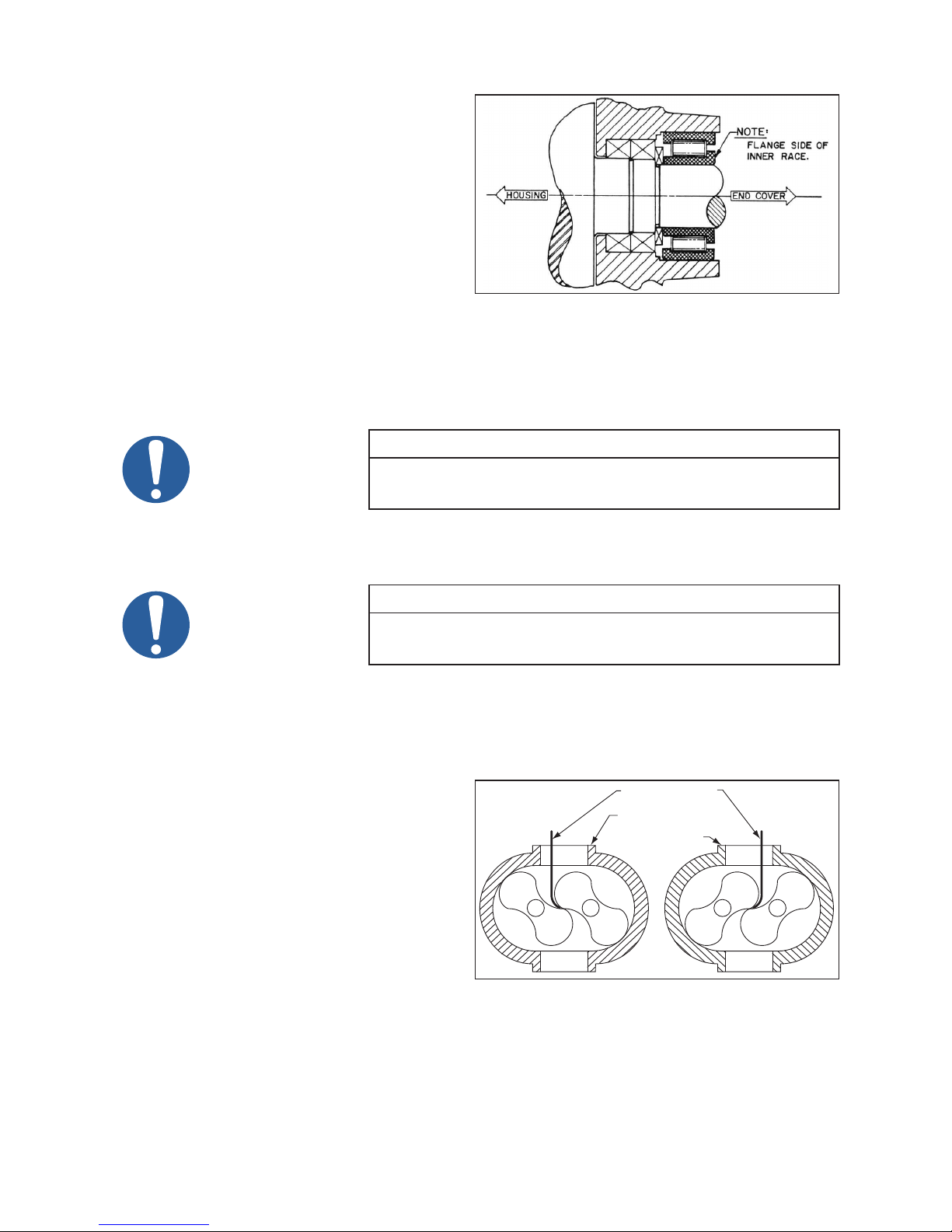
9.2.4 HOUSING AND FREE END ASSEMBLY
11. Place a small bead of sealer around the
periphery of the end plate, encircling each bolt
hole. Install rotor housing [3] and secure with
four screws evenly spaced.
12. Check clearance between the end of lobes and
the housing using a at bar and feeler gauges
or a depth micrometer. Refer to Assembly
Clearances table for free end clearances.
13. Place a small bead of sealer around the
periphery of the housing, encircling each bolt
hole. Install free end plate and secure with
four screws.
Figure 14 - Roller Bearing Flange
14. 90/91 Series - Install mating rings in the
same way as the gear end, No. 5.
92/93 Series - Install seal slinger in the same way as the gear end. Install bearing spacers [123] on
each shaft.
15. Lubricate shafts and install roller bearings [10]
NOTE
Inner race of bearing has a ange on one side only. This ange must face
outward. See Figure 14.
16. Install oil retainer rings and screws [14 & 30], spacer [57] (Model 5500 only), washer [25], screw [29],
oil slinger and dowel [21 & 68], and screw [69].
NOTE
Oil slinger should always be mounted on lower rotor for horizontal ow
17. Lay booster assembly down and torque timing gear nuts at this time. See Torque table on page 41 for
proper torques.
9.2.5 ADJUSTING ROTOR INTERLOBE CLEARANCE
18. Using feeler gauges take interlobe readings
and record on each side of housing as
indicated in Figure 15. By removing or
adding shim behind the helical gear, it rotates
as it is moved in or out and the driven rotor
turns with it, thus changing the clearance
between rotor lobes.
Changing the shim thickness .006” (.15 mm)
will change the rotor lobe clearance .003”
(.08 mm) or one-half the amount.
EXAMPLE: Referring to Figure 15 to the
right, check the clearance a AA (right hand reading) and BB (left hand reading). If AA reading is .009”
(.23 mm) and BB reading .003” (.08 mm) by removing .006” (.15 mm) shims, the readings will change
one-half the amount removed or .003” (.08 mm) AA should then read .006” (.15 mm) and BB should
read .006” (.15 mm). The nal reading should be within .002” (.05 mm) of each other.
To determine the amount of shim to add or remove, subtract the small gure from the larger. If the
units. It can be mounted on either shaft for vertical ow units.
LONG FEELER GAUGE
RECORD A-A
READING HERE
RECORD B-B
READING HERE
BB
A
A
A
B
A
B
A
B
A
Figure 15 - Checking Rotor Interlobe Clearance
A
B
B
B
A
33

right side reading is higher than the left side, remove shim. If the right side reading is lower, add shim.
When removing gear shell from driven gear, it is not necessary to remove gear lock nut. Make sure
bolt locks are in place because the dowel pins must come off with the gear shell.
19. Bend over lock tabs of gear lockwasher [36] and gear screw locks.
Model 5500 - 91/93 series (top drive only). Reinstall oil slinger [20] to lower rotor and secure with
washer [136 & 80] and cap screw [396], if furnished. Not used on older models.
20. Install drive shaft, making sure both surfaces are clean and free of all burrs. Drive shaft runout should
not exceed .003 T.I.R. measured behind keyway.
21. Remove temporary cap screws from end plate and apply a bead of sealer around end plate (not cover),
encircling all holes, and install gear cover [6] and secure with cap screws [26].
NOTE
If cooling coils or manifold screws have been disturbed, they should be
9.2.6 DRIVE SHAFT SEAL ASSEMBLY
22. Install mechanical seal [76] into seal housing [91] and lip seal [13].
23. Install mating ring on shaft.
24. Install assembled seal housing. Be sure to clean and lubricate seals before installing.
9.2.7 COMPLETE BOOSTER ASSEMBLY
retested with air pressure to check for leaks. If leaks occur, disassemble
and replace O-rings [9 & 96]. Mechanical Seal series only
25. Install free end cover [7] following the same procedure used to install the gear cover.
26. Apply sealer and install both port ttings (38 & 48).
27. Install all necessary cooling water lines.
28. Prior to putting booster into operation, follow Installation and Operation instructions. Observe the oil
level frequently, during the initial hours of operation. An improperly installed or damaged oil seal will
result in oil loss.
34
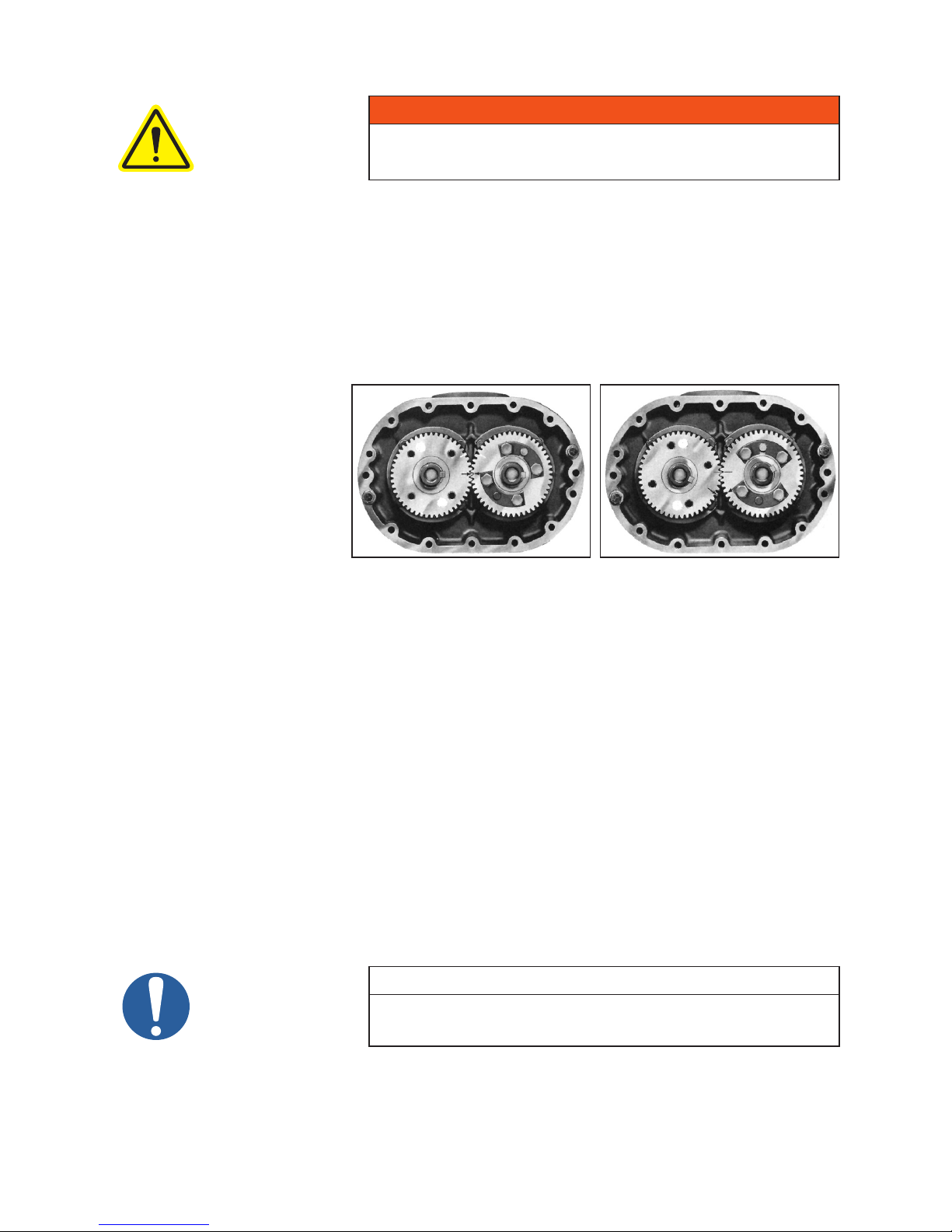
10. MODEL 7000C SERIES DISASSEMBLY AND REASSEMBLY
WARNING
Before performing any repair or replacement, disconnect and lock out
power.
With proper maintenance and lubrication, normal life expectancy for gears, bearings, and seals can
be achieved. However, over a period of time these parts must be repaired or replaced to maintain the
efciency of your booster. This section is written in a way that will allow you to completely disassemble your
booster. The inspection of certain repairable or replaceable parts is referred to at the point of disassembly
where these parts are exposed. If at any point of inspection, repair or replacement is deemed necessary,
appropriate instruction will be given to achieve these repairs or replacements is deemed necessary,
appropriate instruction will be given to achieve these repairs or replacements.
10.1 DISASSEMBLY OF 7000C SERIES BOOSTERS
1. Remove unit from
installation and drain
lubricant from both ends
by removing magnetic
drain plugs (31). Mark
end plates, covers and
housing so they can be
reassembled in their
original position.
2. Remove motor, coupling
and C-ange adapter.
3. Remove four socket head
screws (93). Requires
5/32” hex head (Allen)
wrench. Place two of the screws in tapped jacking holes and remove seal housing (91). Tap out seal
and discard O-rings.
4. Remove gear cover cap screws (26) and gear cover (6) by placing two of the screws in the tapped
jacking holes provided on the cover ange. Support cover with lift straps or other suitable means while
removing. The jackscrews will provide the force necessary to break the seal between cover and end
plate.
5. Temporarily secure end plate to housing with two screws (26) and some at washers. Remove four
nylok screws (66) from drive shaft (45). A light tap with a mallet will break it loose from the gear.
Remove mating ring of mechanical seal [54].
6. Bend back lock tabs and remove cap screws (29), lock (59), washers (25) and spring pins (68).
7. Position timing gears (8) so both timing marks are matched. See Figure 16. Rotate drive gear clockwise
approximately three teeth and mark a matching reference line on each gear as shown in Figure 17.
This gear position is necessary so rotors will clear and not jam. Using a gear puller with a live center or
a centering adapter, large enough so it will not jam into threaded hole, pull driven gear, while keeping
matched reference line marks aligned. Use a slight rocking motion to insure rotors have not jammed.
Should jamming occur, release pressure and tap gear back on until it rotates freely. Pull mating gear.
Figure 16 - Position of timing marks
Keyways in line
and timing marks matched
Figure 17 - Position of timing marks
Timing marks advanced 3 teeth and
reference marks aligned.
NOTE
Never attempt to pull gear when rotors are jammed. Rotor keyway damage
will result.
35

8. Repeat procedure used in No. 4 to remove free end cover (7). Remove rotor shaft screws as was
done in No. 6 and also oil slinger (20). Remove cap screws (30) and oil retainer rings (14).
90 Series: Place ½” eye bolt into both sides of end plate on 90 series, in holes provided for lifting.
91 Series: Place ½” eye bolt into top of end plate on 91 series.
9. Make up four pieces of threaded rod ½”-13 UNC approximately 9” long with double nuts or a single
welded nut to turn rods. On the opposite ends remove about ½” of threads as this end will mushroom
slightly when jacking end plate. This will prevent threads from jamming when removing rods. Run
in equally to remove end plate. Tap out roller bearings (10). Note that each bearing on this end has
two identical spacers (57), one on each side of bearing. Tap out seals (54) or (12). Also remove the
labyrinth seals (51), as they should be replaced with each overhaul.
90/91 Series: discard O-ring (75) and retain O-ring spacers (74) for reassembly.
10. Remove cap screws (30) and bearing retainer rings (14) from drive end of unit. Remove rotors (1). To
remove the rotors from the end plate will require either a two-jaw gear puller with jaws inserted in the
oil feed slots of the bearing bore, or a bar-type puller using the tapped holes around the bearing bore.
CAUTION
If rotors are side by side, position the lobes vertically when removing. If
they are one on top of the other, remove top rotor rst in a vertical position.
Then position bottom rotor vertically and remove.
11. Support end plate with eyebolts and lift strap. Remove temporary cap screws and tap end plate from
housing (3). Remove bearings and seals.
12. Clean and inspect parts for damage and wear. Replace all O-rings, seals and bearings at each overhaul.
NOTE
If end plates, housing or end covers are not being reassembled in their
original position or some new parts are being used, it will be necessary to
clean all paint or rust build-up from the mating surfaces to insure a good
seal. Failure to do so could result in excessive end clearances and air or
oil leaks.
10.2 ASSEMBLY OF 7000C SERIES BOOSTERS
The assembly procedure is generally the same for all series, but where there are differences, notations are
made. Dowel pins are used to locate end plates, housing and end covers in their proper locations relative
to each other. Be sure they are in place. An O-ring lubricant should be used on all O-rings.
It is recommended that the gear end rotor shaft bearings be purchased from Tuthill Vacuum & Blower
Systems, as they are specially ground to locate the rotors with correct end clearance relative to the gear
end plate.
Make sure all parts are clean and free of any nicks or burrs caused by disassembly. Refer to Special Tool
Drawings on page 44-45.
NOTE
When rebuilding the model 7000 blowers and vacuum boosters and
depending on the series designation, it may be necessary to reseal the
joints between the rotor housing, end plates, and end covers. The sealer,
Loctite 515, is recommended and available for purchase from Tuthill
Vacuum & Blower Systems.
10.2.1 PREPARATION OF END PLATES FOR ASSEMBLY
1. Press the labyrinth seals (51) into seal bores with the lips toward the oil side. ( Note:) For lip seal units
put a light coat of silicone in the seal bore of end plate. Install lip seal open side facing up.
2. Install O-ring spacers (74) with grooves up. Install O-rings (75) making sure they are fully seated in
their grooves. Apply a thin coat of sealer to O. D. of seal (54) and press into seal bore. Make sure seals
are fully seated without deforming. Clean seal carbon with soft tissue and cleaning agent (acetone).
36
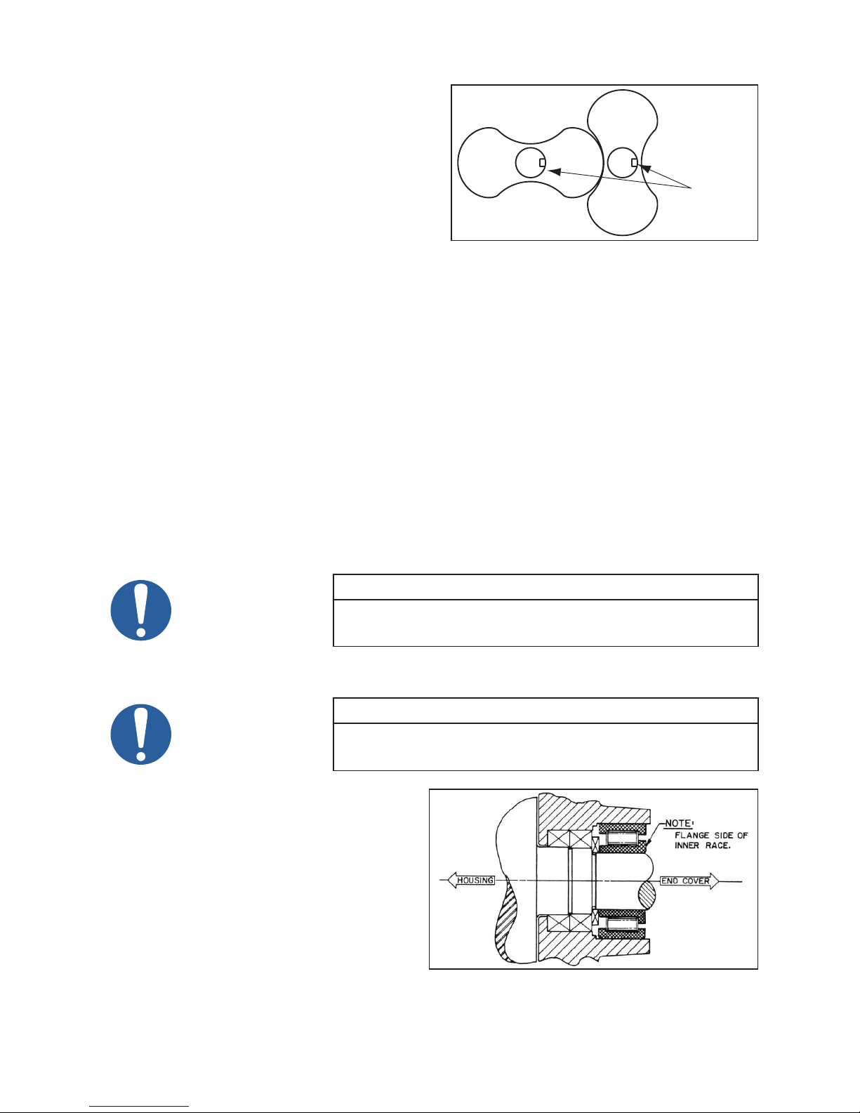
10.2.2 GEAR END ASSEMBLY
Direction
3. Place free end plate on suitable blocking with rotor
side up. Stand rotors (1) into each bore with gear
end shafts up and keyways facing in the direction
shown in Figure 18 to the right.
4. Install the gear end plate (4) over the rotor shafts
and coming to rest on top of the rotor lobes, being
careful not to damage the seals. Recheck the
location of the oil sight glass in relation to the
drive rotor before proceeding with the assembly.
Inspect lapped surface of seal mating ring to be
sure it is perfectly clean. Use a soft tissue and
cleaning agent if necessary. Place a few drops of
lubricating oil on its surface and lubricate the O-ring. Install on rotor shaft with lapped surface down.
Slot must line up with pin (300) in rotor shaft. Gently press with ngers to insure compression is taking
place and mating ring is not hung up for any reason. Top of mating ring should sit ush with rotor
shoulder when fully seated.
5. Coat the rotor shafts with an anti-seize lubricant and press the bearings (9) on the shafts. The bearing
manufacturer numbers and/or an acid dot (inner race) should be up or toward the gears. Use the tool
shown on page 44 along with a length of 3/4 - 10 × 6” threaded rod, washer (25) and nut. The use of
a hydraulic ram with a hollow center is also recommended. In this case the threaded rod will have to
be made longer.
6. Install bearing retainer plates (14) and secure with cap screws (30).
7. Check clearance between the face of the end plate and rotor lobes. Refer to Assembly Clearances table on
page 41 for correct gear end clearances. If clearances are not within specications, recheck parts to
nd cause of improper clearances before proceeding. Install keys (24) in rotor shaft keyways.
8. Lubricate shafts and keys and press drive gear (right hand helix) on drive rotor. To install driven gear,
align reference marks as shown in Figure 17 on page 35. Tap gear with mallet to start then press the
gear until seated.
DRIVE
Keyways
Facing
Same
Figure 18 - Keyways position
NOTE
All timing gears must be used in sets as they are matched and serially
numbered.
9. Install roll pins (68), washers (25), lock tabs (59) and shaft bolts (29). Bend over lock tabs.
NOTE
These bolts are structural bolts, not standard cap screws. Therefore they
10. Remove the gear end assembly from the
free end plate and turn over so the gears are
facing down on a solid surface. Place some
wood blocking on each side for support.
Place a small bead of an RTV silicone type
sealer around the periphery of the housing
[3] bores but inside the bolt pattern. Encircle
the dowel pins. Install rotor housing and
temporarily secure to end plate with two
cap screws [26] and some at washers.
Check clearances between end of lobes and
housing using a at bar and feeler gauges or
a depth micrometer. Refer to exploded view
for free end clearances.
have a larger body diameter and this centers the washers and slinger. Do
not replace with standard cap screws.
Figure 19 - Roller Bearing Flange
37

11. Put sealer on rotor housing, same as above. Install free end plate and secure in same manner.
12. Install seal mating rings as was done in Step 4. Install one bearing spacer (57) on each shaft. Lubricate
shafts and install roller bearing with inner race ange outward. See Figure 19. Install second bearing
spacer (57) on each shaft. Install oil retainer rings (14) and cap screws (30). Install roll pin (68)
washers (25), oil slinger (20) (on drive rotor), lock tabs (59) and bolts (29). Bend over tabs.
13. Install mounting feet (304) with machined surface against housing and secure with lockwashers (80)
and cap screws (307). Install lifting lugs (195) with cap screws (196).
10.2.3 ADJUSTING ROTOR INTERLOBE CLEARANCE
14. The driven gear is made of two pieces. The outer gear shell is fastened to the inner hub with four cap
screws and located with two dowel pins. A laminated shim, made up of .003” (.076 mm) laminations,
separates the hub and the shell. By removing or adding shim laminations, the gear shell is moved
axially relative to the inner hub. Being a helical gear, it rotates as it is moved in or out and the driven
rotor turns with it, thus changing the clearance between rotor lobes. Changing the shim thickness
.014” (.36 mm) will change the rotor lobe clearance .005” (.13 mm).
EXAMPLE: Referring to Figure 15, check the clearance at AA (right hand reading) and BB (left hand
reading). If AA reading is .017” (.43 mm) and BB reading is .004” (.10 mm), by removing.018” (.46
mm) shims, the readings should then read AA .011” (.28 mm) and BB .010” (.25 mm).
To determine the amount of shim to add or remove, subtract the smaller reading from the larger and
multiply the result by 1.4. (.017” [.43 mm] -.004” [.10 mm] = .013” [.33 mm] × 1.4 = .018” [.46 mm])
If the right side reading is higher than the left side, remove shim. If the right side reading is lower,
add shim. The nal readings should be within .002” (.05 mm) of each other. When removing gear
shell from driven gear, it is not necessary to remove gear lock bolt. Make sure bolt locks are in place
because the dowel pins must come off with the gear shell.
15. Install oil slingers (395) back to back on drive shaft ange. Make sure both mating surfaces are clean
and free of burrs-then mount drive shaft to gear and secure with-nylok cap screws (29). Check drive
shaft runout at seal journal. Do not exceed .003” (.08 mm) T.I.R.
16. Remove temporary cap screws from gear end of housing and place bead of silicone around the
periphery of the end plate. Encircle the dowel pins. Install cover (6) and cap screws (26). The use of
two ½”-13 threaded rods as guide screws is recommended.
10.2.4 DRIVE SHAFT SEAL ASSEMBLY
17. Follow steps as listed below:
a. Install O-ring (75) into seal housing (91) and press in stator portions of mechanical seal (54) see
special tool drawing. Clean face of carbon and mating ring with soft tissue and acetone. Install
O-ring (92).
NOTE
Failure to properly pull this gear could result in damage to rotor keyway or
b. Lubricate O-ring in ID of mating ring and carefully slide onto drive shaft with slot up and seat against
shoulder. Do not use any tools. Lapped surface should be facing outward.
c. Install seal housing (91) into cover bore and secure with four hex head screws (93).
d. With set screws (90) in place install mating ring retainer (89) (ange facing outward) while aligning
pin (300) with slot in mating ring. Secure to shaft with set screws.
e. Install dust washer (82) and secure with three hex head screws (111).
a bent rotor shaft. Never use excessive force.
18. Install free end cover (7) same as gear end.
38

10.3 INSTRUCTIONS FOR CONVERTING DRIVES
10.3.1 BOTTOM DRIVE UNITS
If the sight glasses are on the right side as you face the drive shaft you can make a right drive unit by
changing mounting feet, lift lugs, sight glasses and magnetic drain plugs. If the sight glasses are on the left
you can make a left drive unit by changing the same items above.
10.3.2 LEFT OR RIGHT DRIVE UNITS
Can be made bottom drives by changing the same items above.
NOTE
When converting to bottom drive it may be necessary to change the location
of the oil slinger to the bottom rotor.
39

11. TROUBLESHOOTING
Although Tuthill Vacuum & Blower Systems boosters are well designed and manufactured, problems may
occur due to normal wear and the need for readjustment. The chart below lists symptoms that may occur
along with probable causes and remedies.
SYMPTOM PROBABLE CAUSE REMEDIES
Gear housing not tightened
properly.
Lip seal failure. Disassemble and replace lip seal.
Loss of oil
Insufficient sealant. Remove gear housing and replace sealant. See the Disassembly section.
Loose drain plug. Tighten drain plug.
Tighten gear housing bolts.
Excessive
bearing or
gear wear
Lack of
volume
Knocking
Excessive
booster
temperature
Improper lubrication. Correct oil level. Replace dirty oil. See the Lubrication section.
Excessive belt tension. Check belt manufacturer’s specifications for tension and adjust accordingly.
Coupling misalignment. Check carefully, realign if necessary.
Slipping belts. Check belt manufacturer’s specifications for tension and adjust accordingly.
Worn lobe clearances. Check for proper clearances. See the Assembly Clearances section.
Speed too low. Increase booster speed within limits.
Obstruction in piping. Check system to assure an open flow path.
Unit out of time. Re-time.
Distortion due to improper
mounting or pipe strains.
Excessive pressure
differential.
Worn gears. Replace timing gears. See the Disassembly section.
Too much or too little oil in
gear reservoir.
Too low operating speed. Increase booster speed within limits.
Clogged filter or silencer. Remove cause of obstruction.
Excessive pressure
differential.
Elevated inlet temperature. Reduce inlet temperature.
Check mounting alignment and relieve pipe strains.
Reduce to manufacturer’s recommended pressure. Examine relief valve and reset if
necessary.
Check oil level. See the Lubrication section.
Reduce pressure differential across the booster.
Worn lobe clearances. Check for proper clearances. See the Assembly Clearances section.
Insufficient assembled
clearances.
Rotor end or
tip drag
Vibration
Case or frame distortion. Check mounting and pipe strain.
Excessive operating
pressure.
Excessive operating
temperature.
Belt or coupling
misalignment.
Lobes rubbing.
Worn bearings or gears. Check condition of gears and bearings; replace if necessary.
Unbalanced or rubbing
lobes.
Driver or booster loose. Check mounting and tighten if necessary.
Piping resonance. Check pipe supports, check resonance of nearby equipment, check foundation.
40
Correct clearances. See the Assembly Clearances section.
Reduce pressure differential.
Reduce pressure differential or reduce inlet temperature.
Check carefully, realign if necessary.
Check cylinder for hot spots, then check for lobe contact at these points. Correct
clearances. See the Assembly Clearances section.
Possible buildup on casing or lobes, or inside lobes. Remove buildup and restore
clearances.

12. ASSEMBLY CLEARANCES
Values are shown in inches and millimeters.
MODEL
3204
3206
3210
4009
4012
5507
5509
5511
5514
5518
5524
7010
7013
7017
7021
7026
GEAR END FREE END INTERLOBE
.003 - .005
.08 - .13
.003 - .005
.08 - .13
.003 - .005
.08 - .13
.004 - .007
.10 - .18
.004 - .007
.10 - .18
.004 - .007
.10 - .18
.004 - .007
.10 - .18
.004 - .007
.10 - .18
.004 - .007
.10 - .18
.004 - .007
.10 - .18
.004 - .007
.10 - .18
.006 - .009
.15 - .23
.006 - .009
.15 - .23
.006 - .009
.15 - .23
.006 - .009
.15 - .23
.006 - .009
.15 - .23
.006 - .010
.15 - .25
.012 - .017
.30 - .43
.012 - .017
.30 - .43
.011 - .016
.28 - .41
.011 - .016
.28 - .41
.011 - .016
.28 - .41
.013 - .018
.33 - .46
.014 - .019
.36 - .48
.017 - .022
.43 - .56
.021 - .026
.53 - .66
.025 - .030
.64 - .76
.013 - .019
.33 - .48
.016 - .022
.41 - .56
.021 - .027
.53 - .69
.026 - .032
.68 - .81
.031 - .037
.79 - .94
CENTER
TIMED
.010 - .014
.25 - .36
.010 - .014
.25 - .36
.010 - .014
.25 - .36
.010 - .014
.25 - .36
.010 - .014
.25 - .36
TIP-DOWEL
.003 - .007
.08 - .18
.003 - .007
.08 - .18
.003 - .007
.08 - .18
.017 - .022
.43 - .56
.017 - .022
.43 - .56
.007 - .012
.18 - .30
.007 - .012
.18 - .30
.007 - .012
.18 - .30
.007 - .012
.18 - .30
.007 - .012
.18 - .30
.008 - .013
.20 - .33
.008 - .012
.20 - .30
.008 - .012
.20 - .30
.008 - .012
.20 - .30
.008 - .012
.20 - .30
.008 - .012
.20 - .30
TIP-PORT
.006 - .010
15 - .25
.006 - .010
15 - .25
.006 - .010
15 - .25
.006 - .011
.15 - .28
.006 - .011
.15 - .28
.011 - .016
.28 - .41
.011 - .016
.28 - .41
.011 - .016
.28 - .41
.011 - .016
.28 - .41
.011 - .016
.28 - .41
.012 - .017
.30 - .43
.015 - .019
.38 - .48
.015 - .019
.38 - .48
.015 - .019
.38 - .48
.015 - .019
.38 - .48
.015 - .019
.38 - .48
13. TORQUE CHART
Data shown represents “wet” torque values, in foot-pounds (ft.-lbs) and Newton-meters (N-m).
PART DESCRIPTION TORQUE
CAP SCREW 10-32UNF
CAP SCREW 1/4”-20UNC GR5
CAP SCREW 5/16”-18UNC GR5
CAP SCREW 3/8”-16UNC GR5
CAP SCREW 1/2”13UNC GR5
CAP SCREW 5/8”14UNC GR5
CAP SCREW 3/4”-10UNC GR5
4
5
8
10
15
20
33
45
78
106
123
167
260
350
41

RECOMMENDED LUBRICANTS FOR ROTARY BLOWERS AND VACUUM BOOSTERS
Blowers used in hydrogen service should use only PneuLube synthetic oil. Tuthill Vacuum & Blower Systems cannot accept
responsibility for damage to seals, O-rings and gaskets caused by use of synthetic lubricants not recommended by Tuthill Vacuum
and Blower Systems.
14. RECOMMENDED LUBRICANTS
RECOMMENDED MINERAL BASED LUBRICANTS
AMBIENT
TEMPERATURE
0° to 32° F
(-18° to 0° C)
32° to 90° F
(0° to 32° C)
90° to 120° F*
(32° to 50° C)
AMBIENT
TEMPERATURE
0° to 32° F
(-18° to 0° C)
32° to 90° F
(0° to 32° C)
90° to 120° F*
(32° to 50° C)
RECOMMENDED MINERAL BASED, FOOD GRADE LUBRICANTS
AMBIENT
TEMPERATURE
0° to 32° F
(-18° to 0° C)
32° to 90° F
(0° to 32° C)
90° to 120° F*
(32° to 50° C)
SHELL CITGO CHEVRON EXXONMOBIL
TELLUS
TELLUS
®
S2 M 68
(ISO 68)
®
S2 M 100
(ISO 100)
—
A/W 68
(ISO 68)
A/W 100
(ISO 100)
A/W 150
(ISO 150)
RANDO HD 68
(ISO 68)
RANDO HD 100
(ISO 100)
RANDO HD 150
(ISO 150)
RECOMMENDED SYNTHETIC BASED LUBRICANTS**
TUTHILL EXXONMOBIL SHELL
SHC 626
(ISO 68)
PneuLube™
(ISO 100)
Lubricant meeting U.S. FDA regulation
21 CFR 178.3570 governing petroleum products
which may have incidental contact with food,
and USDA H1 requirements
CITGO CLARION
(ISO 68)
CITGO CLARION
(ISO 100)
CONSULT FACTORY CONSULT FACTORY
®
A/W 68
®
A/W 100
SHC 627
(ISO 100)
SHC 629
(ISO 150)
Lubricant meeting U.S. FDA regulations
21 CFR 172.878 and 178.3620(a) for direct
and indirect food contact
CITGO CLARION® 350 FOOD GRADE
MORLINA
MORLINA
(ISO 68)
CONSULT FACTORY
DTE HEAVY MEDIUM
(ISO 68)
DTE HEAVY
(ISO 100)
DTE EXTRA HEAVY
(ISO 150)
®
MORLINA
S4 B 68
(ISO 68)
®
S4 B 100
(ISO 100)
®
S4 B 150
(ISO 150)
RECOMMENDED SYNTHETIC BASED, FOOD GRADE LUBRICANTS
AMBIENT
TEMPERATURE
0° to 32° F
(-18° to 0° C)
32° to 90° F
(0° to 32° C)
90° to 120° F*
(32° to 50° C)
Lubricant meeting U.S. FDA regulation
21 CFR 178.3570 governing petroleum products
which may have incidental contact with food,
and USDA H1 requirements
PneuLube™ FG
(ISO 100)
Lubricant meeting U.S. FDA regulations
21 CFR 172.878 and 178.3620(a) for direct
and indirect food contact
CONSULT FACTORY
RECOMMENDED LUBRICANTS FOR M-D VACUUM BOOSTERS
(90/91, 92/93, 96, 31/33 AND 35/37 SERIES)
REQUIREMENTS
• Suitable for high vacuum service
• 100 cSt @ 40° C
• Vapor pressure of 1 micron or less @ 70° F (21° C)
• Straight mineral (no additives) or PAO synthetic oil
RECOMMENDED GREASE FOR COMPETITOR® PLUS BLOWERS:
TUTHILL CITGO
Tuthill PneuLube™ NLGI #2 premium grade,
petroleum base lithium grease.
* For higher ambient temperatures, please consult the factory.
** Blowers used in oxygen-enriched service should use only Castrol Brayco 1726 Plus non-fl ammable, PFPE synthetic lubricant.
For food grade requirements: Use Citgo Clarion
NLGI No. 2 grade. It meets all requirements of FDA Regulation 21 CFR
178.3570 (the former USDA H-1 approval requirements) for lubricants having
incidental contact with food.
®
Food Grade HTEP grease,
42

NOTES:
43

15. TOOL DRAWINGS
FIGURE 20 — 3200C SEAL PRESSING TOOL (T32018-1)
FIGURE 21 — 3200C SEAL PRESSING TOOL (T32018-2)
NOTE: All dimensions are shown in Inches and millimeters.
3.25
82.6
.06 × 45°
1.5
.25
6.3
MIN R
Ø 1.872 ± .001
.05 × 30°
1.0
47.55 ± .03
Ø 2.50
63.5
Ø 2.25
57.1
MATL P/N: CR1026T0-250050 × 1.75 (44.5) LG
MATL: COLD ROLLED 1026 TUBE,
2.50 (65) OD × .50 (15) WALL × 1.75 (45) LONG
.50
12.7
MIN R
1.50
38.1
.74
18.8
Ø 2.044 ± .001
.002 (.05)
51.90 ± .03
A
Ø 1.885 ± .001
47.55 ± .03
MIN R
TOOL ASSEMBLY FOR END PLATE
LAB SEAL, END PLATE
LIP SEAL AND END PLATE
MECHANICAL SEAL INSTALLATION
-A-
FIGURE 22 — 4000C/5500C SEAL PRESSING TOOL (T11449-1)
4.00
101.6
Ø 1.38 REF
35.05
.12 × 45°
3.048
MATL P/N: CR1026T0-287075 × 4.25 (107.95) LG
MATL: COLD ROLLED 1026 TUBE
2.875 (73.025) OD × 4.25 (107.95) LONG
TOLERANCES:
.XX = ± .01 (0.254)
.XXX = ± .0005 (0.0127)
CHAMFERS = ± 2°
.25
6.35
MIN R
.05 × 30°
1.27
TOOL ASSEMBLY FOR
DRIVE SHAFT MECHANICAL
SEAL INSTALLATION
Ø 2.746 ± .001
69.748 ± .025
Ø 2.50
63.5
FIGURE 24 — 3200C/4000C/5500C GEAR AND EP TOOL (T29603)
SNAP-ON P/N
CJ83-3 OR
EQUIVALENT
FIGURE 23 — 4000C/5500C SEAL PRESSING TOOL (T11449-2)
1.12
28.448
Ø 3.147 ± .001
79.933 ± .03
-A-
Ø 2.757 ± .001
70.028 ± .025
.002 (.05)
A
MIN R
TOOL ASSEMBLY FOR END
PLATE LAB SEAL AND END
PLATE MECHANICAL SEAL
INSTALLATION
MATL P/N: CR1026T0-350050 × 3.25 (82.55) LG
MATL: COLD ROLLED 1026 TUBE
3.50 (88.9) OD × .50 (12.7) WALL × 3.25 (82.55) LONG
NOTE:
TOOLS T11449-1 & T11449-2 ARE USED TO INSTALL MECHANICAL SEAL AND
LABRYINTH SEAL USED ON MODEL 5500 ROTOR SHAFTS.
MECHANICAL SEAL USED ON MODEL 5500 DRIVE SHAFTS AND MECHANICAL
SEAL USED ON MODEL 4000 VACUUM BOOSTER DRIVE SHAFT.
2 REF
50.8
.75
19.02
25.4
1
0.5
12.7
3.00
76.2
25.4
.835
21.209
Ø 3.151 ± .001
80.035 ± .025
.002 (.05)
A
Ø 3.50
MIN R
1
2.63
66.80
88.9
SNAP-ON P/N
CJ66-16-3 OR
EQUIVALENT
MATL P/N: CR1018B0-200075 × 5.50 LG
MATL: COLD ROLLED 1018 BAR,
2.75 (69.85) × 5.5 (139.7) LONG
TOLERANCES:
FRACTIONAL = ± .0005 (0.0127)
CHAMFERS = ± 2°
44
Ø 0.69 (17.52)
3/4-16UNF-2B
R 0.22 (5.58) TYP
0.44 REF
11.17
5.25
133.35

4.62
FIGURE 25 — 7000C LAB SEAL PRESSING TOOL
FIGURE 26 — 7000C MECHANICAL & LIP SEAL TOOL
NOTE: All dimensions are shown in Inches and millimeters.
117.35
4.62
± 0.0025
70.9041
± 0.0635
0.9025
± 0.0025
22.9235
± 0.0635
2.75 Ø
69.85
5.75
146.05
FIGURE 27 — 7000C DRIVE SHAFT
MECHANICAL SEAL INSTALLATION TOOL
Ø 5.121
± 0.001
Ø 130.073
± 0.0254
3.860
98.044
2.25
57.15
45°
49.276
1.940
3.00 Ø
76.2
3.40 Ø
86.36
3.740 Ø
94.996
4.240 Ø
107.696
4.720 Ø
119.888
2.75 Ø
69.85
0.25 R
0.700
17.78
FIGURE 28 — 7000C BEARING PRESSING TOOL
Ø 4.7245
± 0.005
Ø 120.0023
± 0.127
5.75 Ø
146.05
2.77 Ø
70.358
1.25
31.75
58.42
2.30
2.25
57.15
0.625
15.875
0.100
2.54
2.175 Ø
55.245
3.75 Ø
95.25
Ø 4.241
2.00 Ø
± 0.001
Ø 107.721
50.8
± 0.0254
SHARP CORNER
2.93 Ø
74.42
4.22 Ø
107.19
Ø 4.719
± 0.001
Ø 119.863
± 0.0254
4.700 Ø
119.38
1.30
33.02
3.00
76.2
FIGURE 29 — 7000C DRIVE SHAFT BEARING INNER RACE PRESSING TOOL
2.00
50.8
3.50 Ø
88.9
Ø 2.9675
± 0.0025
Ø 75.3745
± 0.0635
Ø 2.6375
± 0.0025
Ø 66.9925
± 0.0635
0.625
15.875
0.62
15.748
2.43 Ø
61.722
9.75
247.65
15°
10.25
260.35
Ø 2.3825
± 0.0025
Ø 60.5155
± 0.0635
45

PARTS LIST FOR MODEL 3200C SERIES
ITEM
NO. DESCRIPTION 90/91 92/93
1 ROTOR 2 2
3 HOUSING 1 1
4 END PLATE 2 2
6 DRIVE END COVER 1 1
7 FREE END COVER 1 1
8 TIMING GEAR SET 1 1
9 BEARING, DRIVE END 2 2
10 BEARING, FREE END 2 2
13 LIP SEAL 1 1
14 BEARING RETAINER 4 4
16 TIMING GEAR SHIM 1 1
17 SPACER 1 1
18 SPACER 1 1
ITEM
NO. DESCRIPTION 90/91 92/93
67 SPACER 2 2
70 SIGHT GLASS 0/1 0/1
76 MECHANICAL SEAL 1 1
79 OIL RETAINER — 4
85 PIPE PLUG 6 6
91 SEAL ADAPTER HOUSING 1 1
92 O-RING 1 1
93 SCREW 4 4
94 COOLING COILS 2 —
98 PIPE PLUG 10 10
118 SHIM 1 1
120 BUSHING 4 —
121 PIPE PLUG 4 4
20 OIL SLINGER 1 1
21 OIL SLINGER ASSEMBLY 1 1
22 DOWEL PINS 6 6
23 DRIVE SHAFT KEY 1 1
24 GEAR KEY 2 2
25 ROTOR SHAFT WASHER 4 4
26A CAP SCREW 12 12
26B CAP SCREW 12 12
29 FLAT SOCKET SCREW 4 4
30 SOCKET SCREW 12 12
31 MAGNETIC PIPE PLUG 2 2
38 PORT FITTING 2 2
40 HEX HEAD CAP SCREW 24 24
45 DRIVE SHAFT 1 1
49 LOCK WIRE 1 1
123 BEARING SPACER 2 2
137 OIL DEFLECTOR — 1
165 CONNECTOR 4 —
166 CONNECTOR 2 —
174 PIPE PLUG 2 2
180 ELBOW 2 —
181 HOSE 1 —
238 SLINGER — 4
241 SOCKET SCREW 12 12
242 SIGHT GLASS FRAME 2 2
243 SIGHT GLASS WINDOW 2 2
244 WINDOW GASKET 2 2
245 FRAME GASKET 2 2
303 COVER PLATE 2 2
309 CAP SCREW 8 8
51 LABYRINTH SEAL 4 —
54 MECHANICAL SEAL 4 —
57 SPACER 1 1
66 SCREW 2 2
46
NOTES:
• QUANTITIES SHOWN ARE MAXIMUM VALUES;
QUANTITIES MAY VARY BETWEEN BLOWER
PARTS KITS ARE AVAILABLE, AS FOLLOWS:
90/91 — P/N 32184
92/93 — P/N 32226

PARTS LIST FOR MODEL 4000C SERIES
ITEM
NO. DESCRIPTION 90/91 92/93
1 ROTOR 2 2
3 HOUSING 1 1
4 END PLATE 2 2
6 DRIVE END COVER 1 1
7 FREE END COVER 1 1
8 TIMING GEAR SET 1 1
9 BEARING, DRIVE END 3 3
10 BEARING, FREE END 2 2
13 LIP SEAL 1 1
14 BEARING RETAINER 2 2
15 OIL RETAINER RING 4 4
21 OIL SLINGER ASSEMBLY 1 1
22 DOWEL PINS 6 6
23 DRIVE SHAFT KEY 1 1
ITEM
NO. DESCRIPTION 90/91 92/93
70 SIGHT GLASS 0 / 1 0 / 1
76 MECHANICAL SEAL 1 1
79 OIL RETAINER — 4
85 PIPE PLUG 4 4
91 SEAL ADAPTER HOUSING 1 1
92 O-RING 1 1
93 SCREW 4 4
94 COOLING COILS 2 —
95 O-RING 4 —
96 O-RING 4 —
97 MANIFOLD SCREW 4 —
98 PIPE PLUG 10 10
118 SHIM 1 1
121 PIPE PLUG 3 3
24 GEAR KEY 2 2
25 ROTOR SHAFT WASHER 2 2
26 CAP SCREW 28 28
29 FLAT SOCKET SCREW 1 1
30 SOCKET SCREW 4 4
31 MAGNETIC PIPE PLUG 2 2
35 GEAR LOCKNUT 2 2
36 GEAR LOCKWASHER 2 2
38 PORT FITTING 2 2
40 HEX HEAD CAP SCREW 28 28
45 DRIVE SHAFT 1 1
51 LABYRINTH SEAL 4 —
54 MECHANICAL SEAL 4 —
61 LOCKPLATE 2 2
62 CAP SCREW 8 8
123 BEARING SPACER 2 2
137 OIL DEFLECTOR — 1
166 CONNECTOR 2 —
174 PIPE PLUG 2 2
180 ELBOW 2 —
181 HOSE 1 —
238 SLINGER — 4
241 SOCKET SCREW 12 12
242 SIGHT GLASS FRAME 2 2
243 SIGHT GLASS WINDOW 2 2
244 WINDOW GASKET 2 2
245 FRAME GASKET 2 2
303 COVER PLATE 2 2
309 CAP SCREW 8 8
65 LOCKPLATE 2 2
66 SCREW 4 4
68 OIL SLINGER PIN 1 1
69 FLAT SOCKET SCREW 1 1
NOTES:
• QUANTITIES SHOWN ARE MAXIMUM VALUES;
QUANTITIES MAY VARY BETWEEN BLOWER
PARTS KITS ARE AVAILABLE, AS FOLLOWS:
90/91 — P/N 40119
92/93 — P/N 40204
47

PARTS LIST FOR MODEL 5500C SERIES
ITEM
NO. DESCRIPTION 90/91 92/93
1 ROTOR 2 2
ITEM
NO. DESCRIPTION 90/91 92/93
70 SIGHT GLASS 0 / 1 0 / 1
3 HOUSING 1 1
4 END PLATE 2 2
6 DRIVE END COVER 1 1
7 FREE END COVER 1 1
8 TIMING GEAR SET 1 1
9 BEARING, DRIVE END 2 2
10 BEARING, FREE END 2 2
13 LIP SEAL 1 1
14 BEARING RETAINER 4 4
20 OIL SLINGER 0 / 1 0 / 1
21 OIL SLINGER ASSEMBLY 1 1
22 DOWEL PINS 6 6
23 DRIVE SHAFT KEY 1 1
24 GEAR KEY 2 2
25 ROTOR SHAFT WASHER 1 1
76 MECHANICAL SEAL 1 1
79 OIL RETAINER — 4
80 WASHER 0 / 1 0 / 1
85 PIPE PLUG 6 6
91 SEAL ADAPTER HOUSING 1 1
92 O-RING 1 1
93 SCREW 4 4
94 COOLING COILS 2 —
95 O-RING 4 —
96 O-RING 4 —
97 MANIFOLD SCREW 4 —
98 PIPE PLUG 6 6
123 BEARING SPACER 2 2
136 LOCKWASHER 0 / 1 0 / 1
166 CONNECTOR 2 —
26 CAP SCREW 28 28
29 FLAT SOCKET SCREW 1 1
30 SOCKET SCREW 6 6
31 MAGNETIC PIPE PLUG 2 2
35 GEAR LOCKNUT 2 2
38 PORT FITTING 1 / 2 1 / 2
40 HEX HEAD CAP SCREW 28 28
45 DRIVE SHAFT 1 1
48 PORT FITTING (5507) 1 / 0 1 / 0
51 LABYRINTH SEAL 4 —
54 MECHANICAL SEAL 4 —
57 SPACER 1 1
61 LOCKPLATE 6 6
62 CAP SCREW 12 12
65 LOCKPLATE 2 2
66 SCREW 4 4
68 OIL SLINGER PIN 1 1
69 FLAT SOCKET SCREW 1 1
174 PIPE PLUG 2 2
180 ELBOW 2 —
181 HOSE 1 —
238 SLINGER — 4
241 SOCKET SCREW 12 12
242 SIGHT GLASS FRAME 2 2
243 SIGHT GLASS WINDOW 2 2
244 WINDOW GASKET 2 2
245 FRAME GASKET 2 2
303 COVER PLATE 2 2
309 CAP SCREW 8 8
NOTES:
• QUANTITIES SHOWN ARE MAXIMUM VALUES;
QUANTITIES MAY VARY BETWEEN BLOWER
PARTS KITS ARE AVAILABLE, AS FOLLOWS:
90/91 — P/N 55272
92/93 — P/N 55399
48

PARTS LIST FOR MODEL 7000C SERIES
ITEM
NO. DESCRIPTION 90/91
1 ROTOR 2
ITEM
NO. DESCRIPTION 90/91
75 O-RING 5
3 HOUSING 1
4 END PLATE 2
6 DRIVE END COVER 1
7 FREE END COVER 1
8 TIMING GEAR SET 1
9 BEARING, DRIVE END 2
10 BEARING, FREE END 2
13 LIP SEAL 1
14 RETAINER 2
15 RETAINER 2
20 OIL SLINGER 1
22 DOWEL PIN 8
23 DRIVE SHAFT KEY 1
80 WASHER 4
85 PIPE PLUG 14
89 LOCKING RING 1
90 SET SCREW 3
91 LIP SEAL 1
92 O-RING 1
93 CAP SCREW 4
94 COOLING COILS 2
95 O-RING 4
96 O-RING 4
97 BUSHING 4
98 PIPE PLUG 4
174 PIPE PLUG 4
24 GEAR KEY 2
25 ROTOR SHAFT WASHER 4
26 CAP SCREW 36
29 BOLT 4
30 CAP SCREW 16
31 MAGNETIC PIPE PLUG 2
45 DRIVE SHAFT 1
51 LABYRINTH SEAL 4
54 MECHANICAL SEAL 5
49 LOCKING TAB 4
66 CAP SCREW 4
68 ROLL PIN 4
70 SIGHT GLASS 2
74 SEALING RING 4
195 LIFTING LUG 2
196 CAP SCREW 2
199 O-RING 2
300 ROLL PIN 5
304 FOOT 2
307 CAP SCREW 4
339 STRAIGHT PLUG 6
395 OIL SLINGER 2
499 BUSHING 1
NOTES:
• QUANTITIES SHOWN ARE MAXIMUM VALUES;
QUANTITIES MAY VARY BETWEEN BLOWER
PARTS KITS ARE AVAILABLE, AS FOLLOWS:
90/91 — P/N 77165
49
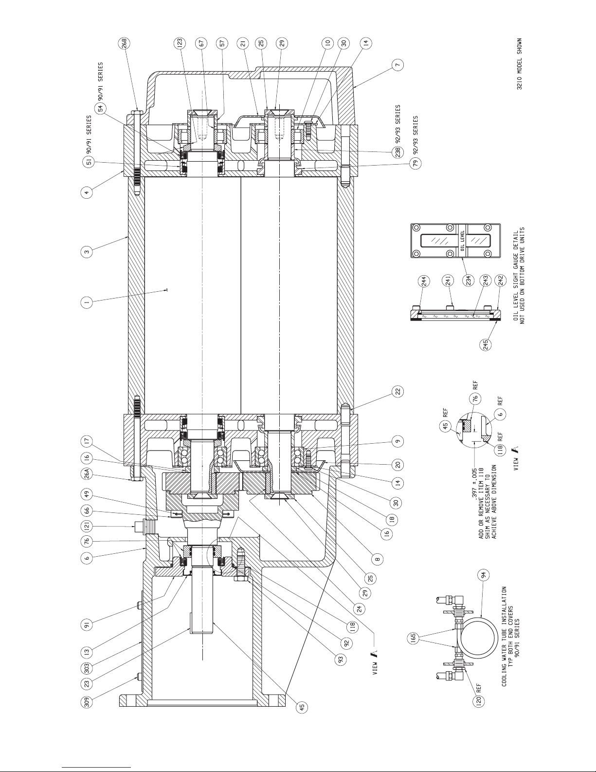
3200C CUTAWAY DRAWING — 3200-90C/91C/92C/93C, 1 OF 2 (A)
50
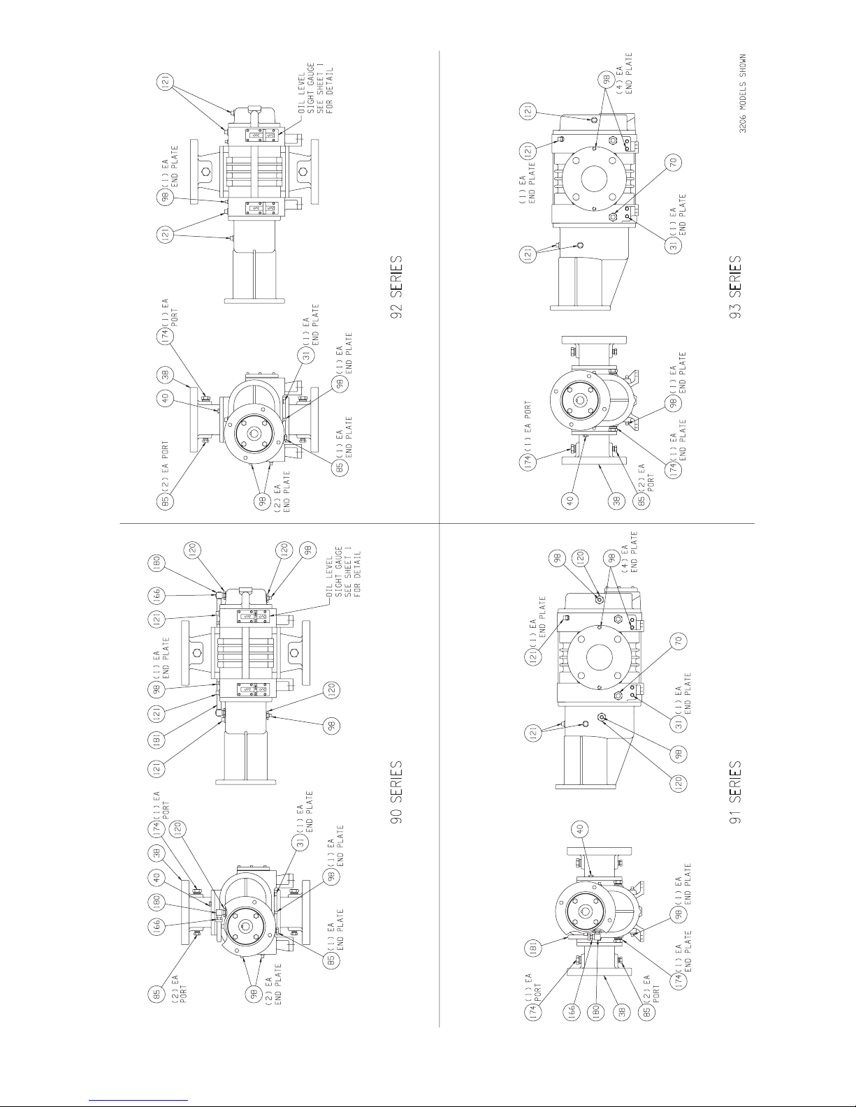
3200C CONFIGURATIONS DRAWINGS — 3200-90C/91C/92C/93C, 2 of 2 (A)
51
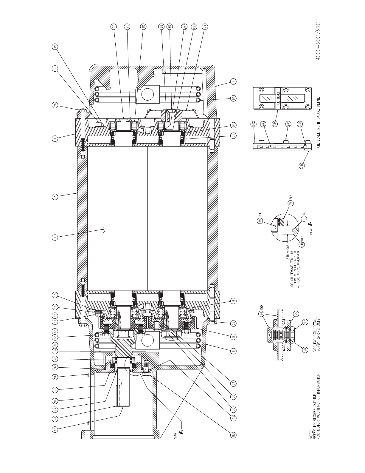
VIEW
25
NOTE:
REFER TO BLOWER OUTLINE
FOR MOTOR MOUNTING KIT INFORMATIO
29
1530
10
69
68
377
21
123
4000-90C/91C
OIL LEVEL
243
234
5451 794
242
241
244
OIL LEVEL SIGHT GAUGE DETAIL
245
3 4 26
REF45
REF76
REF
6
VIEW
REF
118
.545 ±.005
SHIM AS NECESSARY TO
ADD OR REMOVE ITEM 118
ACHIEVE ABOVE DIMENSION
4000C CUTAWAY DRAWING — 4000-90C/91C/92C/93C, 1 OF 2 (D)
9145 30323 13 92309 34137 6676 65 61 62 14 15 1
52
9
REF94
22
95
97
90/91 SERIES ONLY
96
COOLING COIL DETAIL
N
24 6 8
93 36118 35
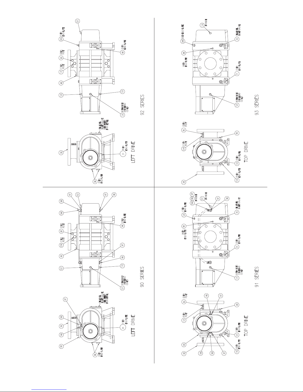
121
(1) EA
END PLATE
345
(2) EA
END PLATE
(2) EA
PORT
85
(1) EA
PORT
174
40
98
(1) EA END PLATE
345
98
(4) EA
END PLATE
FARSIDE
121
OIL LEVEL
SIGHT GAUGE
70
(1) EA
END PLATE
31
121
OIL LEVEL
SIGHT GAUGE
(SEE SHEET 1
FOR DETAIL)
38
98
(2) EA
END PLATE
97
121
180
166
(2) EA
PORT
8540121
(1) EA
PORT
174
97
121
COVER
BOTH SIDES
DRIVE END
COVER
BOTH SIDES
DRIVE END
121
(1) EA
END PLATE
31
98
(2) EA
END PLATE
98
97
92 SERIES
(2) EA
85
(1) EA
38 174
(1) EA
121
98
(4) EA
93 SERIES
PORT
40 121
PORT
(1) EA
END PLATE
121
(1) EA
END PLATE
174
97
FARSIDE
121
180166
FARSIDE
END PLATE
END PLATE
98
97
OIL LEVEL
SIGHT GAUGE
70
(1) EA
END PLATE
4000C CONFIGURATIONS DRAWING — 4000-90C/91C/92C/93C, 2 OF 2 (D)
97
180
38166
181
OIL LEVEL
98
(2) EA
END PLATE
SIGHT GAUGE
98
121
COVER
BOTH SIDES
DRIVE END
121 31
COVER
BOTH SIDES
DRIVE END
121
(SEE SHEET 1
FOR DETAIL)
(1) EA
END PLATE
31
90 SERIES
LEFT DRIVE LEFT DRIVE
(2) EA
85
(1) EA
18138 174
PORT
PORT
97
98
40
(1) EA
END PLATE
121
(1) EA
END PLATE
174
97
180
166
91 SERIES
TOP DRIVE TOP DRIVE
53
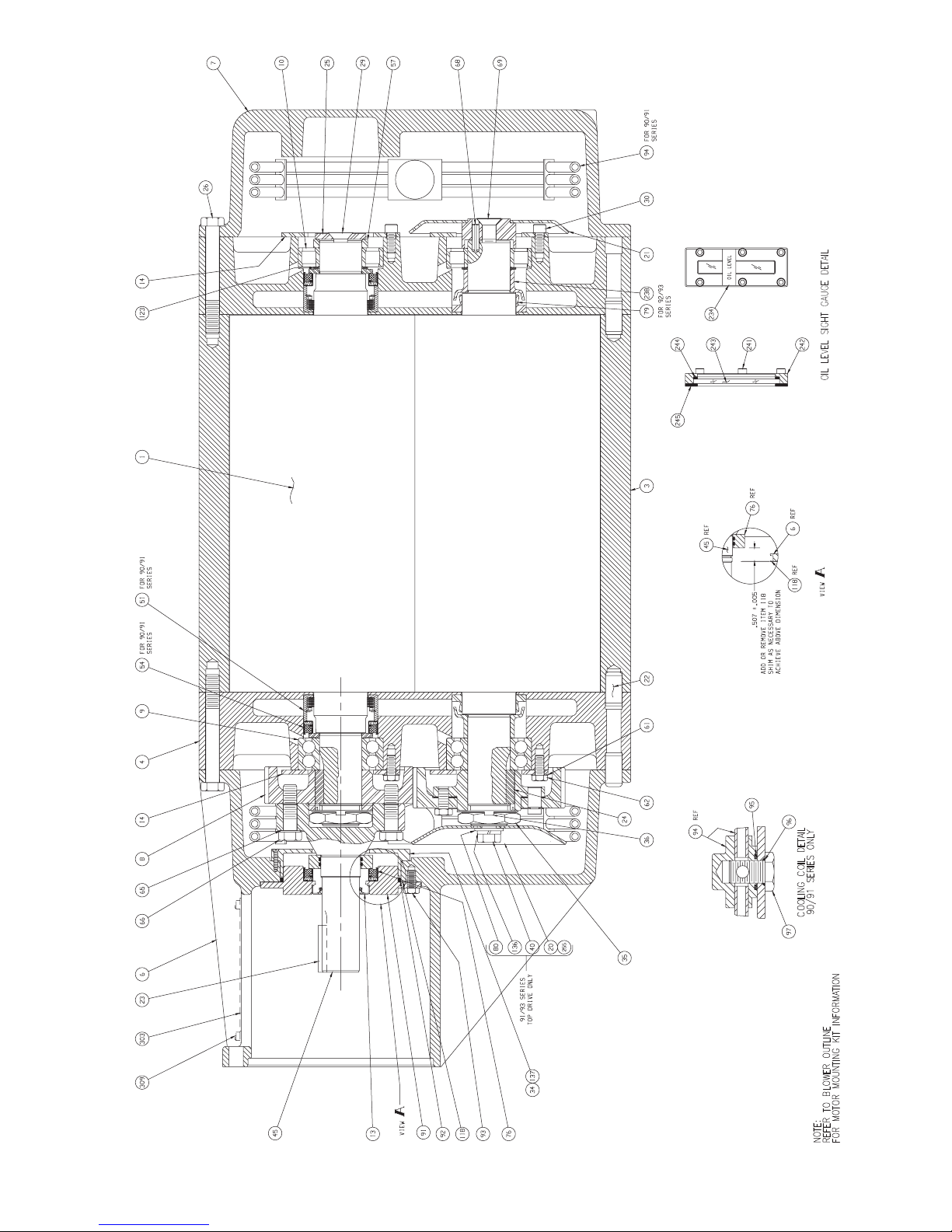
OIL LEVEL SIGHT GAUGE DETAIL
5500C CUTAWAY DRAWING — 5500-90C/91C/92C/93C, 1 OF 2 (E)
54

5500C CONFIGURATIONS DRAWINGS — 5500-90C/91C/92C/93C, 2 of 2 (E)
55

7000C CUTAWAY DRAWING — 7000-90C/91C, 1 OF 3 (–)
56
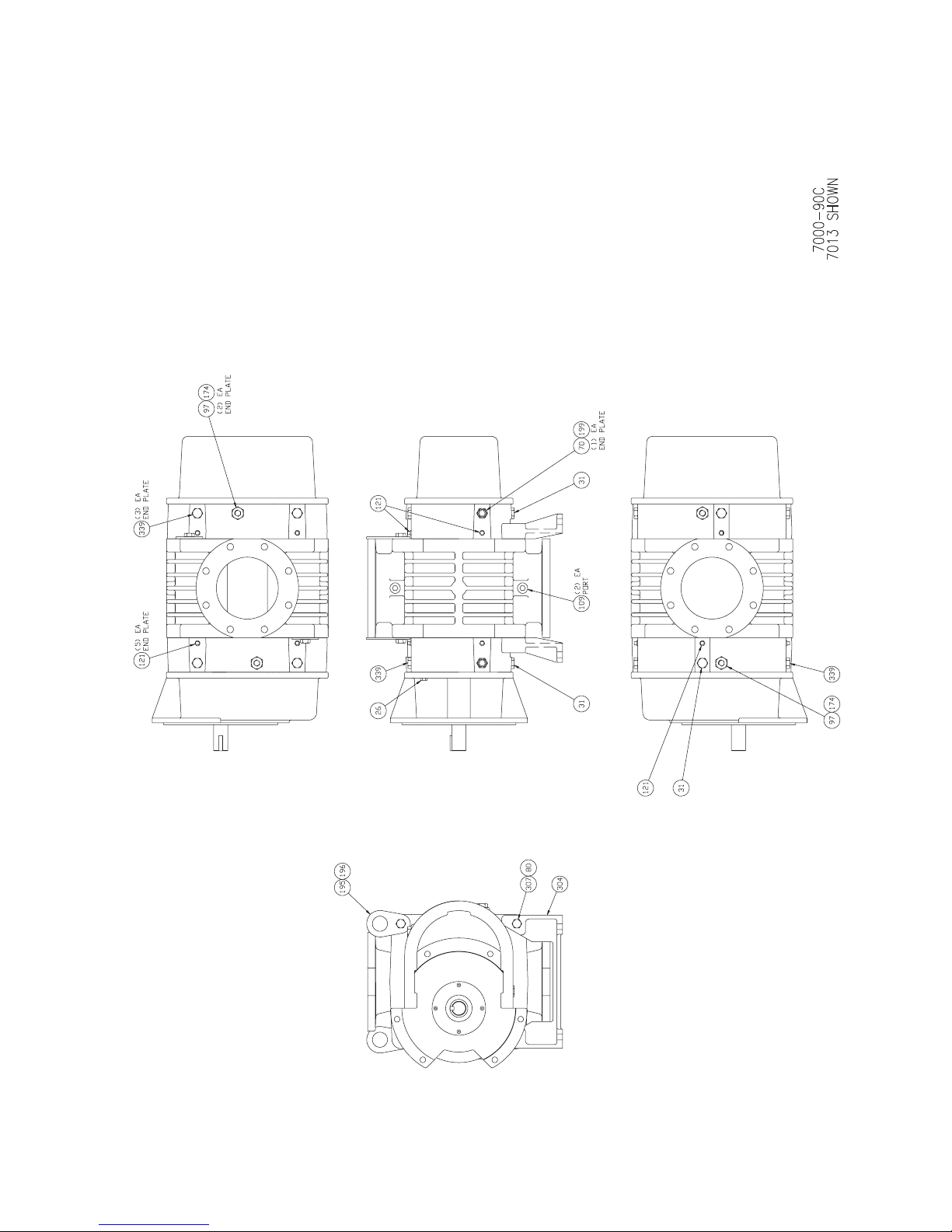
7000C CONFIGURATIONS DRAWING — 7000-90C, 2 OF 3 (–)
57

7000-91C
7013 SHOWN
7000C CONFIGURATIONS DRAWING — 7000-91C, 3 OF 3 (–)
58

32172-180TC
32172-180TCC
32172-210TCC
32172-210TC
M-D PART NO.
32172-140TC
32172-140TCC
MOTOR
(ITEM 4)
(QTY 4)
MTG SCREWS
BOOSTER
90295-100
90293-100
90293-100
90295-100
90295-100
90295-100
(ITEM 3)
(ITEM 2)
(ITEM 1)
3200C – MOTOR ADAPTER KIT (NEMA) – 32172 (A)
PART NO.
COUPLING
(QTY 4)
ADAPTER
MTG SCREWS
ADAPTER
FRAME
MOTOR
90032-100
PART NO.
32166-145
145TC
31718-063087087
90032-100
32166-145
145TC
31718-063087112
90032-100
90032-100
32166-200
32166-200
182TC & 184TC
182TC & 184TC
31718-063087137
90032-100
90032-100
32166-200
32166-200
213TC & 215TC
213TC & 215TC
4
2 3
1
P
P
P
MOTOR
59

32173-112CP
32173-132
32173-132CP
32173-112
32173-90C
32173-9
M-D PART NO
(ITEM 6)(ITEM 5)
MOTOR MTG
LOCKWASHER
(QTY 4)
80040-10
80040-10
80040-12
80040-12
80040-12
80040-12
BOOSTER
(QTY 4)
HEX NUTS
MOTOR MTG
(QTY 4)
SCREWS
(ITEM 4)
MOTOR MTG
(ITEM 3)(ITEM 2)
PART NO.
COUPLING
(QTY 4)
ADAPTER
MTG SCREWS
80024-12
80024-12
80024-10
80024-10
92288-40
90032-100
80005-45
92288-40
31790-063022024
90032-100
90032-100
80024-12
80005-45
80005-45
31790-063022028
90032-100
90032-100
80024-12
80005-45
31790-063022038
4
2 3
90032-100
6
3200C – MOTOR ADAPTER KIT (IEC) – 32173 (B)
ADAPTER
(ITEM 1)
MOTOR
PART NO.
32168-090
90
FRAME
32168-112
32168-090
90
110/112
.
P
0
60
32168-112
32168-132
32168-132
132
132
110/112
1
5
MOTOR

254TC/256TC
MOTOR
213TC/215TC
254TC/256TC
213TC/215TC
(ITEM 4)
CAP SCREWS
MOTOR MOUNTING
(QTY)
P/N
90170-100 (4)
90170-100 (4)
90170-100 (4)
90170-100 (4)
BOOSTER
90170-175 (4)31718-063100162
90170-175 (4)
(ITEM 3)
(ITEM 2)
(ITEM 1)
P/N
COUPLING
(QTY)
CAP SCREWS
P/N
ADAPTER MOUNTING
NUMBER
ADAPTER PART
---
90032-125 (4)
40108-200
---
31718-063100112
90032-125 (4)
90032-125 (4)
40108-200
40108-200
---
31718-063100137
90032-175 (4)40108-250-250TCCP
90032-175 (4)
90032-125 (4)
40108-250
40108-200
2
3
4000C – MOTOR ADAPTER KIT (NEMA) – 40111 (C)
-180TC
NUMBER
KIT DASH
FRAME
MOTOR
184TC
-210TC
-180TCCP
184TC
-250TC
-210TCCP
4
1
61

MOTO
110/112
110/112
R
(ITEM 4)
(ITEM 6)
(ITEM 5)
P/N QTY
LOCKWASHER
MOTOR MOUNTING
NUTS
P/N QTY
MOTOR MOUNTING
P/N QTY
CAP SCREWS
MOTOR MOUNTING
80040-14 (4)
80040-14 (4)
80024-14 (4)
80024-14 (4)
80006-45 (4)
80006-45 (4)
BOOSTE
80040-16 (4)
80040-14 (4)
80024-14 (4)
80006-45 (4)
80040-16 (4)
80040-14 (4)
80024-16 (4)80007-80 (4)
80024-16 (4)
80024-14 (4)
80007-80 (4)
80006-45 (4)
4000C – MOTOR ADAPTER KIT (IEC) – 40110 (B)
---
P/N
(ITEM 3)
COUPLING
(ITEM 2)
CAP SCREWS
P/N QTY
ADAPTER MOUNTING
NUMBER
(ITEM 1)
ADAPTER PART
KIT DASH
40107-112
-112 90032-100 (4)
NUMBER
---
31790-063025028
90032-100 (4)
90032-125 (4)
40107-112
40107-132
-132
-112CP
---
31790-063025038
31790-06302504240107-160
2
90032-125 (4)
90032-125 (4)
90032-125 (4)
46
40107-160
40107-132
5
-160
-132CP
-160CP
1 3
FRAME
MOTOR
62
132
160
132
160
R

MOTO
NUMBER
-250TCC
-280TSCC
-210TCC
BLOWER
4
31718-073137137
4
4
---
4
4
(ITEM 4)
CAP SCREWS
P/N 90295-125
MOTOR MOUNTING
P/N
(ITEM 3)
COUPLING
(ITEM 2)
CAP SCREWS
ADAPTER MOUNTING
---
4
P/N 90170-125
4
31718-073137162
4
4
4
---
31718-073137162
4
4
NUMBER
(ITEM 1)
ADAPTER PART
55223-230
55223-230
55223-230
5000C – MOTOR ADAPTER KIT (NEMA) – 55228 (B)
FRAME
MOTOR
213TC/215TC
213TC/215TC
P
DASH
-210TC 55223-230
254TC/256TC
254TC/256TC
P
-250TC
55223-280
55223-280
284TSC/286TSC
284TSC/286TSC
P
-280TSC
4 2
1 3
R
63

MOTO
NUMBER
-160CP
-180CP
-132CP
(ITEM 6)
LOCKWASHER
MOTOR MOUNTING
NUTS
(ITEM 5)
BOOSTER
80040-14 (4)
80040-16 (4)
80040-14 (4)
80040-16 (4)
80040-16 (4)
80040-16 (4)
80024-14 (4)
MOTOR MOUNTING
QTY
(ITEM 4)
(ITEM 2)
5000C – MOTOR ADAPTER KIT (IEC) – 55227 (B)
P/N
CAP SCREWS
MOTOR MOUNTING
(ITEM 3)
ADAPTER MOUNTING
80006-70 (4)
P/N
---
COUPLING
4
CAP SCREWS
P/N 90170-125
80024-16 (4)
80024-14 (4)
80007-80 (4)
80006-70 (4)
---
31790-073032038
4
4
80024-16 (4)
80024-16 (4)
80007-80 (4)
31790-073032042
4
80024-16 (4)
80007-80 (4)
80007-80 (4)
---
31790-073032048
4
4
2
31
NUMBER
(ITEM 1)
64
55224-132
55224-132
ADAPTER PART
132S
FRAME
MOTOR
DASH
-132
55224-170
132S
160L/160M
-160
55224-170
160L/160M
55224-170
55224-170
5 6 4
180L/180M
180L/180M
-180
R
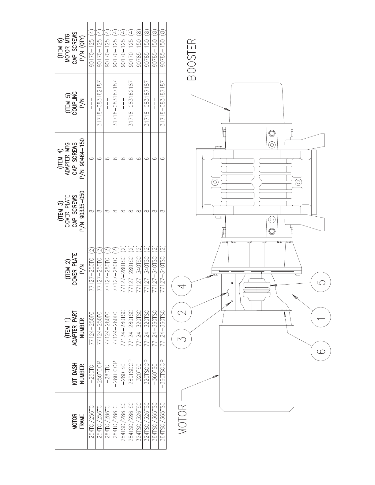
324TSC/326TSC
324TSC/326TSC
364TSC/365TSC
364TSC/365TSC
254TC/256TC
284TC/286TC
284TSC/286TSC
284TSC/286TSC
284TC/286TC
254TC/256TC
(ITEM 6)
MOTOR MTG
CAP SCREWS
P/N (QTY)
90785-150 (8)
90785-150 (8)
90785-150 (8)
90170-125 (4)
90170-125 (4)
90170-125 (4)
90170-125 (4)
90170-125 (4)
90170-125 (4)
90785-150 (8)
BOOSTER
(ITEM 5)
COUPLING
(ITEM 4)
CAP SCREWS
ADAPTER MTG
(ITEM 3)
CAP SCREWS
COVER PLATE
(ITEM 2)
COVER PLATE
P/N
---
31718-083162187
6
6
P/N 90464-150
8
8
P/N 90335-050
P/N
77127-250TC (2)
77127-250TC (2)
---
---
31718-083187187
666
6
888
8
77127-280TC (2)
77127-280TC (2)
77127-280TSC (2)
31718-083162187
77127-280TSC (2)
---
31718-083187187
6
6
8
8
77127-340TSC (2)
77127-340TSC (2)
---
31718-083187187
6
6
8
8
77127-340TSC (2)
77127-340TSC (2)
7000C – MOTOR ADAPTER KIT (NEMA) – 77131 (B)
(ITEM 1)
NUMBER
77124-280TC
77124-280TC
77124-250TC
ADAPTER PART
KIT DASH
MOTOR
77124-250TC
-250TC
NUMBER
-250TCCP
FRAME
77124-280TSC
-280TC
-280TSC
-280TCCP
77124-320TSC
77124-320TSC
77124-280TSC
-280TSCCP
77124-360TSC
-320TSC
-360TSC
-320TSCCP
77124-360TSC
-360TSCCP
3 42
MOTOR
6 1 5
65

NOTE:
110MM X 60MM DIA SHAFT
140MM X 60MM DIA SHAFT
225S/225M [2]
225M [1]
225S/225M [2]
225M [1]
160L/160M
160L/160M
180L/180M
180L/180M
4
(ITEM 8)
LOCKWASHER
P/N 80040-16
MOTOR MOUNTING
NUTS
(ITEM 7)
MOTOR MTG
(ITEM 6)
CAP SCREWS
MOTOR MOUNTING
4
P/N 80024-16
4
P/N 80007-60
4
444
4
444
4
4
44431790-083048048
8
4
8
4
8
8
8
8
8
8
8
BOOSTER
8
8
8
(ITEM 5)
COUPLING
(ITEM 4)
CAP SCREWS
ADAPTER MOUNTING
(ITEM 3)
CAP SCREWS
COVER PLATE
P/N
---
6
P/N 90464-150
8
P/N 90335-050
---
31790-083042048
666
6
888
8
---
31790-083048055
6
8
7000C – MOTOR ADAPTER KIT (IEC) – 77129 (B)
P/N
(ITEM 2)
COVER PLATE
77127-170 (2)
77127-170 (2)
77127-170 (2)
77127-170 (2)
77127-200 (2)
77127-200 (2)
---
6
8
77127-225 (2)
---
31790-083048060
6
8
77127-225 (2)
31790-083048055
6
6
8
8
77127-225X (2)
77127-225X (2)
2 3
7 8 6
5 4
1
NUMBER
(ITEM 1)
ADAPTER PART
NUMBER
KIT DASH
FRAME
MOTOR
77122-170
77122-170
77122-170
-160 77122-170
-160CP
-180
-180CP
66
77122-225
77122-200
77122-200
-200
-200CP
200L
200L
77122-225
77122-225X
-225
-225CP
-225X
77122-225X
-225XCP
MOTOR
[1]
[2]

SHAFT DIAMETER
DRIVE COUPLING (U.S. CUSTOMARY) – 31718 (–)
DRIVE COUPLING (METRIC) – 31790 (–
OVER THRU
.438
.562
.875
1.250
1.375
1.750
2.250
2.750
3.250
3.750
.562
.875
1.250
1.375
1.750
2.250
2.750
3.250
3.750
4.500
KEY
.125 X .125
.188 X .188
.250 X .250
.312 X .312
.375 X .375
.500 X .500
.625 X .625
.750 X .750
.875 X .875
1.000 X 1.000
COUPLING SLEEVE
THIRD
DIGIT OF
DASH NO.
2 N
3
4
TYPE
E1
HS
H
CONSTRUCTION
AND MATERIAL
2 PIECE
EPDM
2 PIECE
NEOPRENE
2 PIECE
HYTREL
1 PIECE
HYTREL
WOOD'S SURE-FLEX COUPLING
TYPE S
DASH NO. EQUALS COUPLING SIZE, TYPE SLEEVE
AND BORE SIZES IN INCHES & HUNDREDTHS
EXAMPLE:
31718-073137162
COUPLING SIZE
LARGER (OR EQUAL)
BORE SIZE
162=1.625 Ø BORE
*SEE NOTE
*NOTE:
BORE SIZES HAVE STANDARD
SQUARE KEYWAYS. SEE CHART
SHAFT DIAMETER
OVER THRU
12
17
22
30
38
44
50
58
65
75
9585110
17
22
30
38
44
50
58
65
75
85
95
KEY
5 X 5
6 X 6
8 X 7
10 X 8
12 X 8
14 X 9
16 X 10
18 X 11
20 X 12
22 X 14
25 X 14
28 X 16
THIRD
DIGIT OF
DASH NO.
COUPLING SLEEVE
TYPE
1 E
N2
HS3
4 H
)
CONSTRUCTION
AND MATERIAL
2 PIECE
EPDM
2 PIECE
NEOPRENE
2 PIECE
HYTREL
1 PIECE
HYTREL
COUPLING SLEEVE
(SEE TABLE)
DASH NO. EQUALS COUPLING SIZE, TYPE SLEEVE
AND BORE SIZES IN MILLIMETERS
EXAMPLE:
31790-063028038
COUPLING SIZE
COUPLING SLEEVE
(SEE TABLE)
SMALLER (OR EQUAL)
BORE SIZE
137=1.375 Ø BORE
*SEE NOTE
WOOD'S SURE-FLEX COUPLING
TYPE S
LARGER (OR EQUAL)
BORE SIZE
038=38MM Ø BORE
*SEE NOTE
SMALLER (OR EQUAL)
BORE SIZE
028=28 MM Ø BORE
*SEE NOTE
*NOTE:
BORE SIZES HAVE STANDARD
METRIC SQUARE OR RECTANGULAR
KEYWAYS. SEE CHART
67

NOTES:
68

DECLARATION OF INCORPORATION
Herewith we declare that the items detailed below are in conformity with the provisions
of the Machinery Directive 2006/42/EC.
Information on the items detailed are compiled per the Machinery Directive 2006/42/EC,
Annex VII, part A and are the responsibility of the person listed below.
The items detailed below must not be put into service until the machinery into which it
is to be incorporated has been declared in conformity with the provisions of the relevant
directive(s).
Other directives and standards that apply to this Declaration of Incorporation:
EN 1012-2:1996 - Compressors and vacuum pumps - Safety requirements -
Part 2: Vacuum Pumps
The scope of the Declaration of Incorporation is for M-D Pneumatics™ C-Flange
Mechanical Vacuum Boosters
MODEL 3200(M)C, 4000(M)C, 5500(M)C AND 7000(M)C
90/92 SERIES – VERTICAL FLOW
91/93 SERIES – HORIZONTAL FLOW
The person authorized to compile the technical file is Xavier Lambert, Tuthill Corporation,
Parc Industriel Wavre Nord-Avenue Vesale 30, B-1300 Wavre Belgium.
David Schardt
VP of Engineering & Product Development
Tuthill Vacuum & Blower Systems
4840 West Kearney Street
P.O. Box 2877
Springeld, MO USA 65801-0877
69

WARRANTY – BLOWER PRODUCTS
Subject to the terms and conditions hereinafter set forth and set forth in General Terms of Sale, Tuthill Vacuum & Blower
Systems (the Seller) warrants products and parts of its manufacture, when shipped, and its work (including installation
and start-up) when performed, will be of good quality and will be free from defects in material and workmanship. This
warranty applies only to Seller’s equipment, under use and service in accordance with seller’s written instructions,
recommendations and ratings for installation, operating, maintenance and service of products, for a period as stated in
the table below. Because of varying conditions of installation and operation, all guarantees of performance are subject
to plus or minus 5% variation. (Non-standard materials are subject to a plus or minus 10% variation)
PRODUCT
TYPE
New
(Qx™ models only)
New
(all other models)
Repair
ATMOSPHERIC AIR OR PROCESS AIR
WITHOUT LIQUIDS PRESENT
30 months from date of shipment, or 24 months after
initial startup date, whichever occurs first.
24 months from date of shipment, or 18 months after
initial startup date, whichever occurs first
12 months from date of shipment, or remaining warranty
period, whichever is greater
TYPE OF APPLICATION
PROCESS GASES OTHER THAN AIR,
OR ANY LIQUID INJECTED APPLICATION
Consult Factory
18 months from date of shipment, or 12 months after
initial startup date, whichever occurs first
12 months from date of shipment, or remaining
warranty period, whichever is greater
THIS WARRANTY EXTENDS ONLY TO BUYER AND/OR ORIGINAL END USER, AND IN NO EVENT SHALL THE
SELLER BE LIABLE FOR PROPERTY DAMAGE SUSTAINED BY A PERSON DESIGNATED BY THE LAW OF ANY
JURISDICTION AS A THIRD PARTY BENEFICIARY OF THIS WARRANTY OR ANY OTHER WARRANTY HELD TO
SURVIVE SELLER’S DISCLAIMER.
All accessories furnished by Seller but manufactured by others bear only that manufacturer’s standard warranty.
All claims for defective products, parts, or work under this warranty must be made in writing immediately upon discovery
and, in any event within one (1) year from date of shipment of the applicable item and all claims for defective work must
be made in writing immediately upon discovery and in any event within one (1) year from date of completion thereof by
Seller. Unless done with prior written consent of Seller, any repairs, alterations or disassembly of Seller’s equipment
shall void warranty. Installation and transportation costs are not included and defective items must be held for Seller’s
inspection and returned to Seller’s Ex-works point upon request.
THERE ARE NO WARRANTIES, EXPRESSED, IMPLIED OR STATUTORY WHICH EXTEND BEYOND THE
DESCRIPTION ON THE FACE HEREOF, INCLUDING WITHOUT LIMITATION, THE IMPLIED WARRANTIES OF
MERCHANTABILITY AND FITNESS OF PURPOSE.
After Buyer’s submission of a claim as provided above and its approval, Seller shall at its option either repair or replace
its product, part, or work at the original Ex-works point of shipment, or refund an equitable portion of the purchase price.
The products and parts sold hereunder are not warranted for operation with erosive or corrosive material or those
which may lead to build up of material within the product supplied, nor those which are incompatible with the materials
of construction. The Buyer shall have no claim whatsoever and no product or part shall be deemed to be defective by
reason of failure to resist erosive or corrosive action nor for problems resulting from build-up of material within the unit
nor for problems due to incompatibility with the materials of construction.
Any improper use, operation beyond capacity, substitution of parts not approved by Seller, or any alteration or repair
by others in such manner as in Seller’s judgment affects the product materially and adversely shall void this warranty.
No employee or representative of Seller other than an Officer of the Company is authorized to change this warranty in
any way or grant any other warranty. Any such change by an Officer of the Company must be in writing.
The foregoing is Seller’s only obligation and Buyer’s only remedy for breach of warranty, and except for gross
negligence, willful misconduct and remedies permitted under the General Terms of Sale in the sections on CONTRACT
PERFORMANCE, INSPECTION AND ACCEPTANCE and the PATENTS Clause hereof, the foregoing is BUYER’S
ONLY REMEDY HEREUNDER BY WAY OF BREACH OF CONTRACT, TORT OR OTHERWISE, WITHOUT REGARD
TO WHETHER ANY DEFECT WAS DISCOVERED OR LATENT AT THE TIME OF DELIVERY OF THE PRODUCT
OR WORK. In no event shall Buyer be entitled to incidental or consequential damages. Any action for breach of this
agreement must commence within one (1) year after the cause of action has occurred.
May 2008

OPERATING DATA FORM / PRODUCT REGISTRATION
It is to the user’s advantage to have the requested data filled in below and available in the event a problem should
develop in the blower or the system. This information is also helpful when ordering spare parts.
Model No. V-Belt Size Length
Serial No. Type of Lubrication
Startup Date
Pump RPM Operating Vacuum
Pump Sheave
Diameter Any other Special Accessories Supplied or in use:
Motor Sheave
Diameter
Motor RPM HP
NOTES:
IMPORTANT
All blowers manufactured by Tuthill Vacuum & Blower Systems are date coded at time of shipment. In order
to assure you of the full benefits of the product warranty, please complete, tear out and return the product
registration card, or register online at tuthillvacuumblower.com.

For Service & Repair, Technical Support,
or Product Sales contact:
Tuthill Vacuum & Blower Systems
4840 West Kearney Street
Springeld, Missouri USA 65803-8702
O 417.865.8715 800.825.6937 F 417.865.2950
tuthillvacuumblower.com
T
S
E
I
R
G
E
E
D
R
VACUUM & BLOWER SYSTEMS
TUTHILL CORPORATION
I
N
T
A
E
D
R
N
N
A
A
T
T
S
I
O
Y
N
T
I
A
L
L
A
Q
U
Manual 2000 0811 ENG
D
R
 Loading...