

Page 1

01
03
04
07
10
11
12
14
20
22
23
24
1.Warning
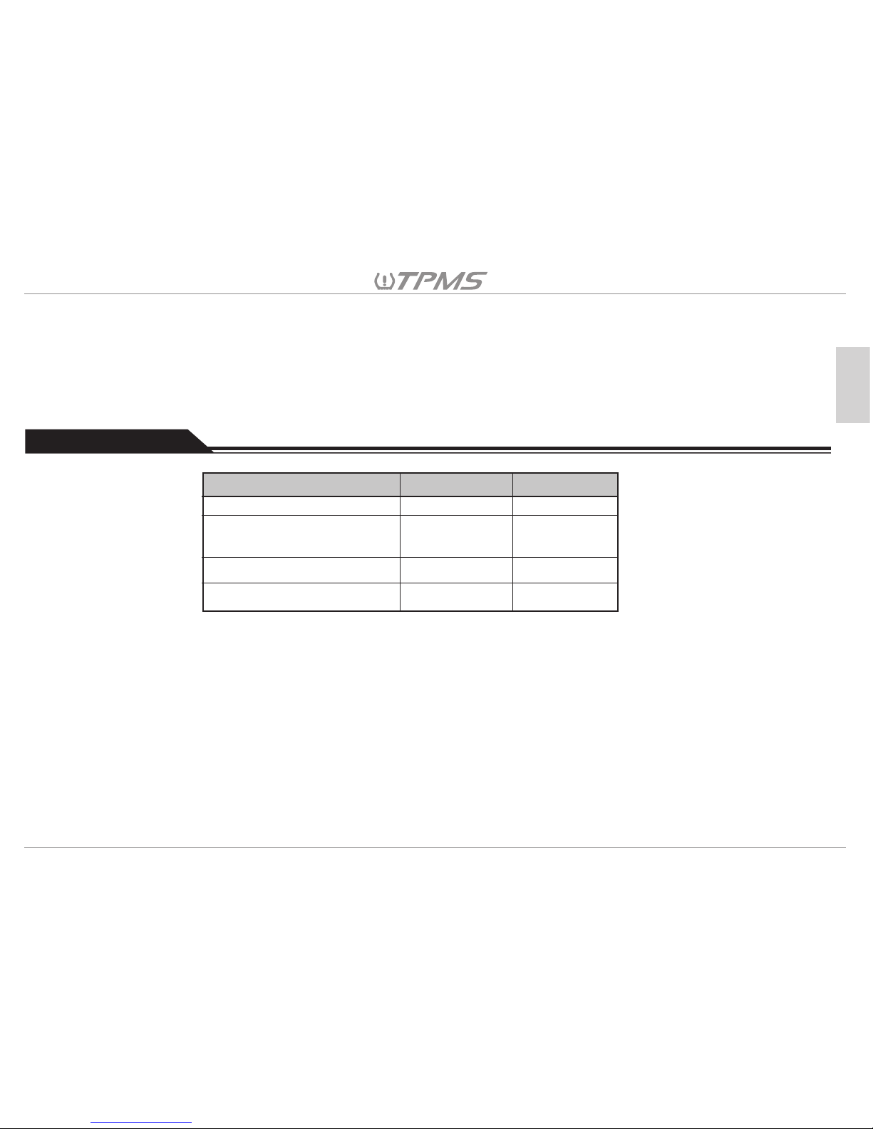
2.Product Parts List
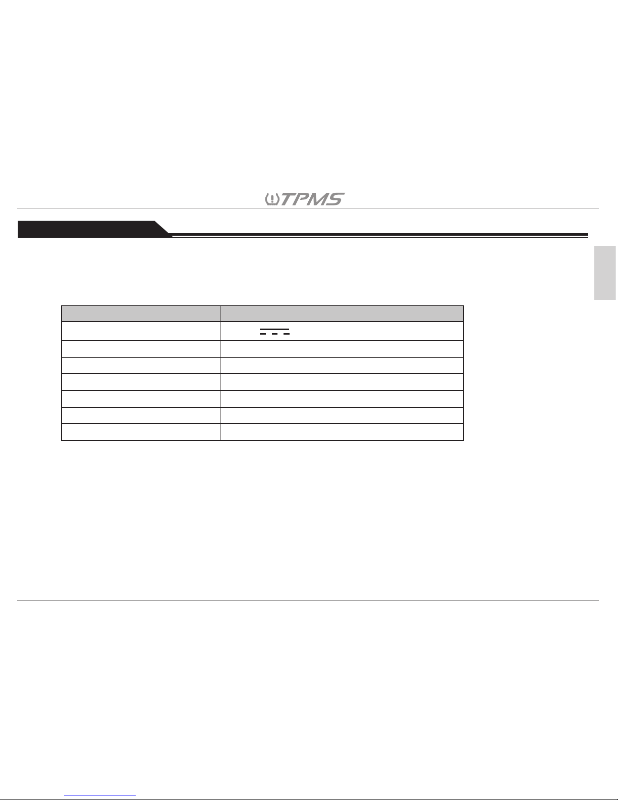
3.Product Specifications
4.TPM Sensor Installation
5.TPM Receiver Installation
6.TPMS Repeater Installation
7.Driving Mode Menu
8.Setting Mode Menu
9.Alarm Warnings and Display Symbols
10.Troubleshooting
11.Customer Service
Limited Warranty
Contents
English
Tuson TPMS Retrofit Kit User Manual
Page 2

1. Warning
1.1 Federal Communication Commission Interference Statement:
This equipment has been tested and found to comply with the limits for a Class B digital device,
pursuant to Part 15 of the FCC Rules. These limits are designed to provide reasonable protection
against harmful interference in a residential installation. This equipment generates, uses and can
radiate radio frequency energy and, if not installed and used in accordance with the instructions, may
cause harmful interference to radio communications. However, there is no guarantee that interference
will not occur in an installation. If this equipment does cause harmful interference to radio or television
reception, which can be determined by turning the equipment off and on, the user is encouraged to
try to correct the interference by one of the following measures:
01
English
Reorient or relocate the receiving antenna.
Increase the separation between the equipment and receiver.
Connect the equipment into an outlet on a circuit different from that to which the receiver is
connected.
Consult the dealer or an experienced radio/TV technician for help.
FCC Caution: Any changes or modifications not expressly approved by the party responsible for
compliance could void the user's authority to operate this equipment.
This device complies with Part 15 of the FCC Rules. Operation is subject to the following two
conditions: (1) This device may not cause harmful interference, and (2) this device must accept any
interference received, including interference that may cause undesired operation.
Page 3
1.2.1
Do not operate a TPMS receiver while driving. The company is exempt from all consequences because
of driver’s careless and improper operation.
1.2.2
The system adopts the wireless transmission of signals. In some special circumstances, interference or
erroneous methods of operation or installation method errors may cause weaker signal or its inability to
receive signals. If the insulation adhesive sticker of the windshield contains metal material, it will be likely
to affect reception conditions.If the tire pressure and temperature readings on the TPMS receiver are
displayed as “---”, this condition represents the receiver cannot receive signals emitted by the sensors.
Drive the vehicle away from the current location (nearby there may be signal interference) or drive the
vehicle to a tire shop to check.
1.2 Product Warning
02
English
1.2.4
Temporary resealing or re-inflation products containing internal sealants or propellants in any tire
assembly may adversely affect the operation of the sensor/transmitter. The product manufacturer does
not assume any liability as a result of these.
1.2.5
Do not leave the sensors in contact with chemicals, it may cause the sensors to fail.
1.2.3
If the battery status of the TPMS sensors inside the tire is low (because abnormal conditions continue to
occur, the battery may make the TPMS sensors continuously emit signals to warn the driver, so that
battery life is shorter than the normal life), Please go as soon as possible to the specified service stations
to confirm whether the TPMS Sensors need to be replaced.
Page 4
03
English
1
Part No.
2. Product Parts List
64
4
6
1.2.6
The TPMS needs to be installed by qualified personnel in accordance with the installation manual in
order for the TPMS warranty to be valid. If the TPMS sensor is improperly installed or disassembled
causing damage to the sensors, the warranty will not cover this type of damage.
Accessories in the box:
• Cigarette Lighter Cable (Vin=12~24V) x 1
• Suction Cup Holder x 1
• Cable Tie x 5
• User Manual x 1
• Warranty Card x 1
Sensor
Interchangeable
Valve Stem(0.625” / 0.453”)
TPMS Receiver (Monitor)
Repeater
TPMS4W TPMS6W
1
1
1
Page 5
04
English
3. Product Specifications
Operating Voltage
Operating Frequency
Operating Temperature
Storage Temperature
Pressure Monitoring Range
Temperature Monitoring Range
Weight
ITEM Specification
3V DC
433MHz
-22°F~257°F (-30°C~125°C)
-40°F~185°F (-40°C~85°C)
0~203 psi±1.5 psi (0 ~ 1400 kPa±10 kPa)
-40°F~257°F±5.4°F (-40°C~125°C±3°C)
30 g (1 Oz)
3.1 Sensor Specifications
Vehicle Types for TPMS use (Maximum 6-wheel): Tuson TPMS is designed for all types of RVs,
commercial and livestock trailers. Great for commercial and passenger vehicles as well!
Page 6
05
English
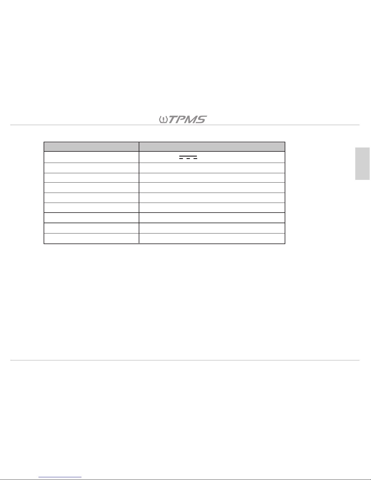
Operating Voltage
Operating Current
Operating Frequency
Operating Temperature
Storage Temperature
Monitored Pressure Range
Monitored Temperature Range
Size
Weight
ITEM Specification
12~24V DC
120 mA
433 MHz
-4°F~185°F (-20°C~85°C)
-40°F~185°F (-40°C~85°C)
0~203±1.5psi (0~1400±10kPa)
-40°F~257°F±5.4°F (-40°C~125°C±3°C)
4.5”x2.1”x1” (116.5 x 53 x 25 mm)
3.4 Oz (95g)
3.2 Repeater Specifications
Note: When using kPa as the unit of air pressure, the monitor will display “Hi” if the air
pressure is over 999kPa. Air pressure values will be displayed normally when the unit of
measure selected is in psi or Bar.
Page 7
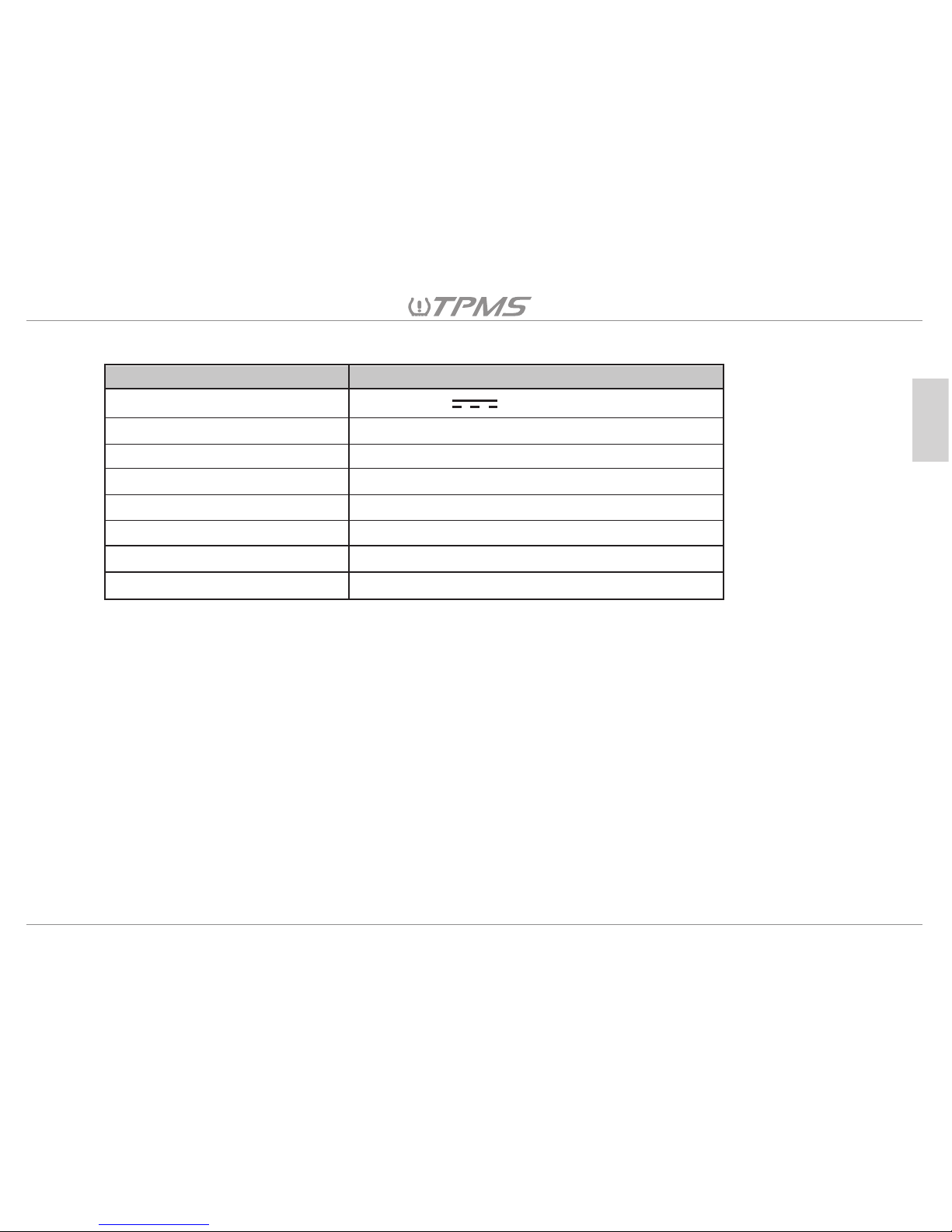
06
English
Operating Voltage
Operating Current
Operating Frequency
Operating Temperature
Storage Temperature
Cable Length
Size
Weight
ITEM Specification
12~24V DC
11.2 mA
433 MHz
-4°F~185°F (-20°C~85°C)
-40°F~185°F (-40°C~85°C)
90 inches (2300 mm)
3.5”x3.8”x0.9” (88 x 96 x 23 mm)
6 Oz (170g)
3.3 Repeater Specifications
Page 8
4. TPMS Sensor Installation
07
English
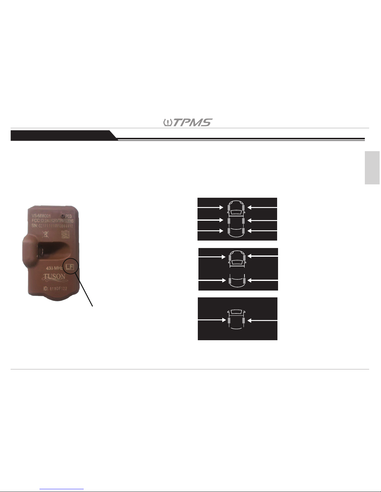
<IMPORTANT 1>
There is a wheel orientation mark on the surface of the sensor (see Fig 1), please
install the sensors on the corresponding wheels (see Fig 2) on the trailer. If sensors
are properly installed according to the corresponding wheels in Fig 2, then “8.5
Setting the Tire Position on the Receiver” can be skipped during the first installation
and save time.
Wheel orientation mark
LF – Driver Front
RF – Passenger Front
RF – Passenger Front
LR – Driver Middle
RR – Passenger Middle
TL – Driver Rear
TR – Passenger Rear
TL – Driver Rear
TR – Passenger Rear
RR – Passenger Middle
LF – Driver Front
LR – Driver Middle
Page 9
08
English
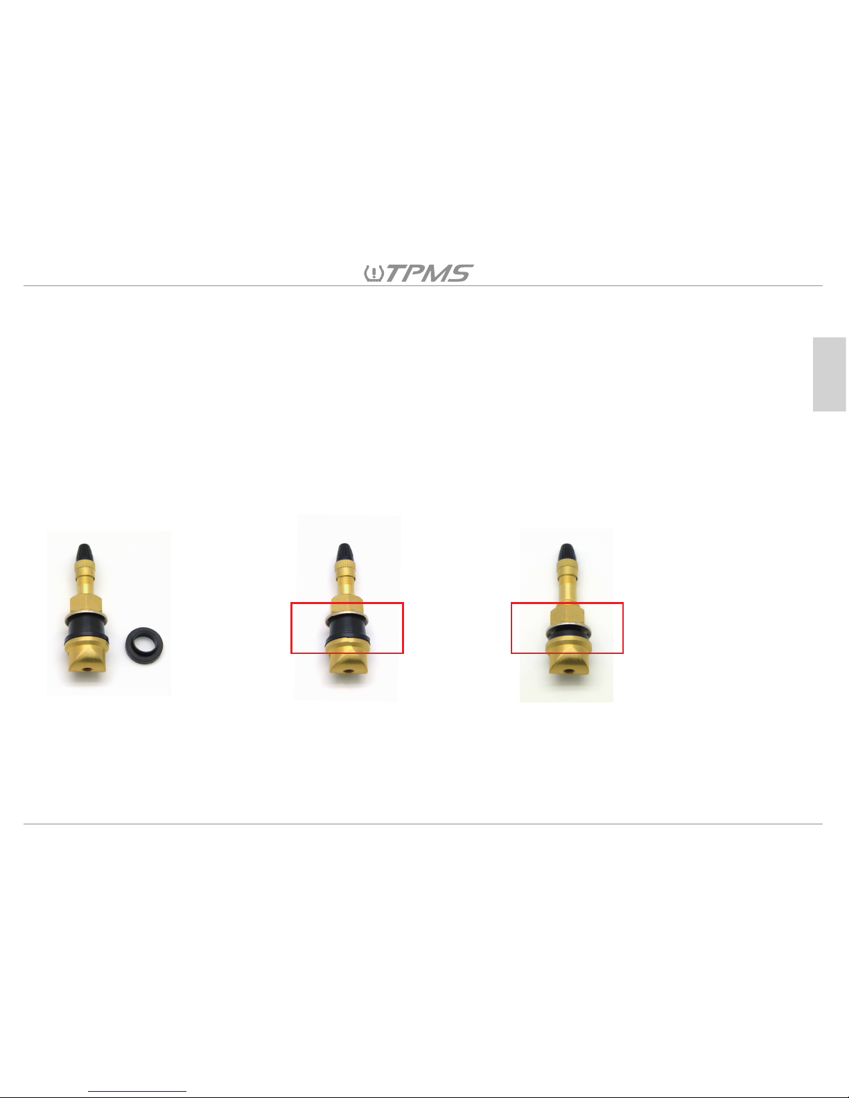
<IMPORTANT 2>
The Interchangeable Valve Stem ( IVS ) Service Kit
The Tuson TPMS tire sensor uses a metal interchangeable valve stem (IVS) that fits through 0.453" and 0.625" in.
diameter rim holes. Great for trailer, caravan, motorhome and passenger & commercial vehicle wheels.
Please circle the grommet size that was used for your tire application for easy identification and replacement:
0.453” OR 0.625”
Each IVS service kit comes with two (2) rubber grommet sizes: one (1) fits 0.453” rim holes and one (1) fits 0.625” rim
holes. The IVS should be installed using a single grommet only. Do not use both sizes of the included grommets to install
the valve stem. Please check and make sure that the correct grommet size is used for the valve stem and fits the rim hole
prior to TPMS sensor installation.
Please use the
preassembled 0.625”
grommet on the valve
stem if the rim hole is
0.625”.
When the rim hole of the wheel is 0.453”,
disassemble the valve stem and remove
the 0.625” grommet from the valve stem
and assembly the 0.453” grommet, ring
and nut in order.
The IVS service kit comes
preassembled with the 0.625”
grommet on the valve stem and an
individual 0.453” grommet in the
polybag.
Page 10
09
English
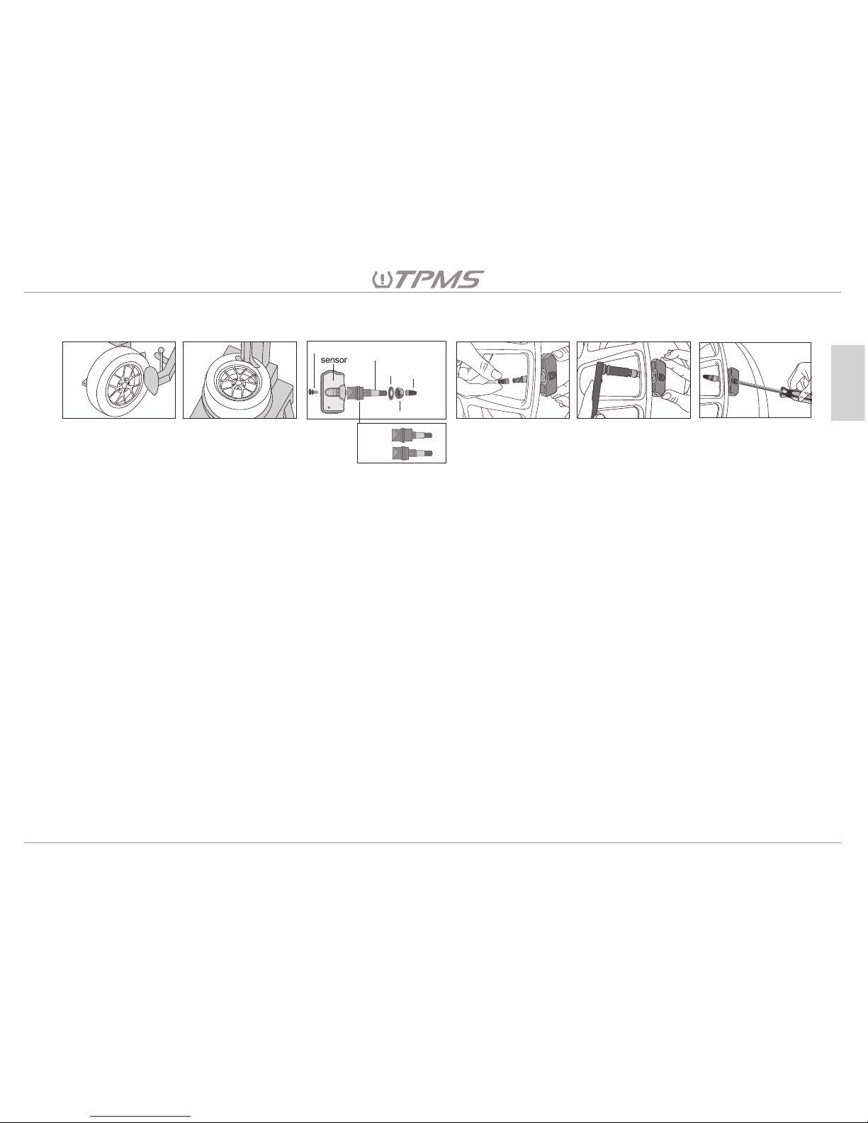
4.1 TPMS Sensor Installation:
(Fig 1) (Fig 2) (Fig 3) (Fig 4) (Fig 5) (Fig 6)
gromment(0.625” or 0.453’’)
screw
nut
cap
washer
metal valve stem
0.625”
0.453’’
(Fig 1) & (Fig 2) Deflate and remove the tire from the wheel using a tire mounting machine.
(Fig 3) Assemble the sensor to the metal valve stem using the screw (make sure the correct grommet size is on the metal
valve stem), then remove the cap, nut and washer from the metal valve stem.
(Fig 4) Insert the metal valve stem through the rim hole. Then place the back of the sensor body to face the inner surface
of the rim, so that the sensor is parallel to the rim.
(Fig 5) Holding the sensor in place, guide the washer onto the metal valve stem on the outside of the rim hole. Then secure
the nut on the metal valve stem and tighten to 2.95 Ft-lbs (4 N-m) torque. Once secured, affix the cap to the metal
valve stem.
(Fig 6) Secure the sensor to the metal valve stem by tightening the screw to 1.48 Ft-lbs (2N-m) torque.
Now remount the tire back onto the wheel, being careful not to damage the tire pressure sensor during mounting of the
tire.Lastly, balance the wheel as you would normally, adding weights if necessary to achieve rotational balance.
Page 11
kPa
psi
Bar
C
F
+
-
OK
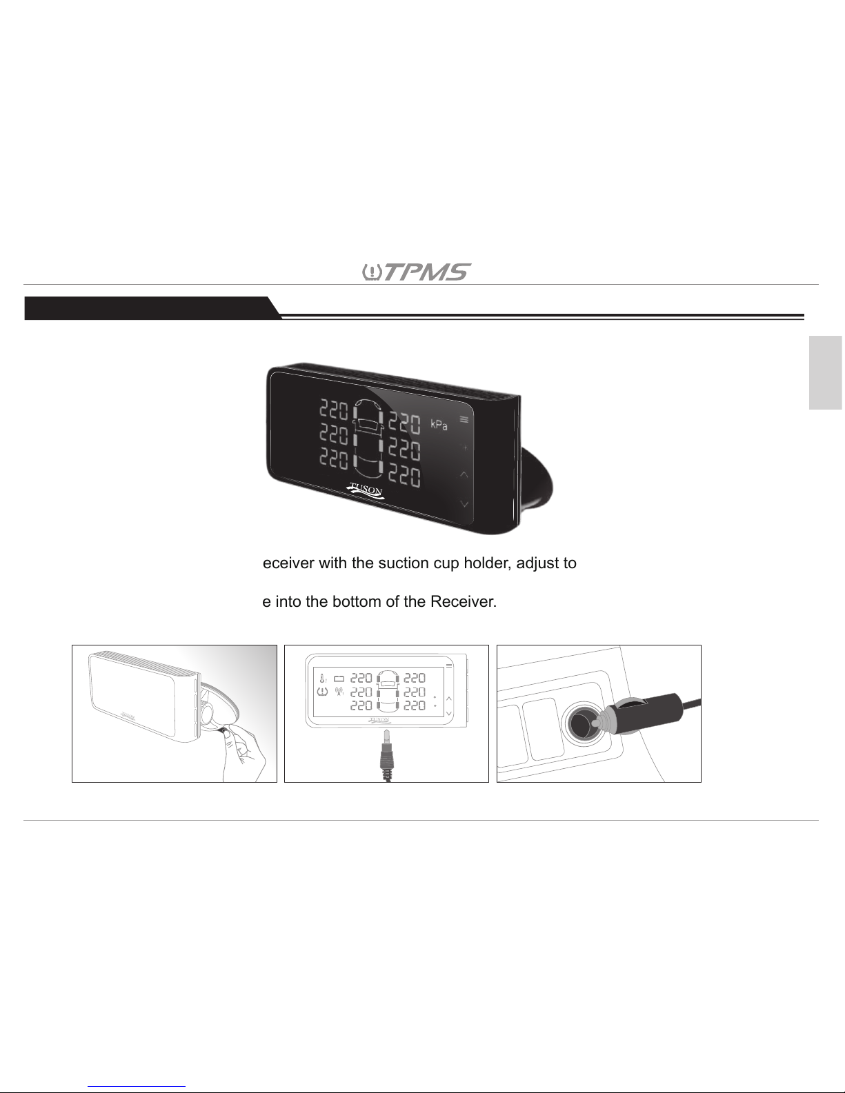
5.2 Installation Steps
5.2.1. Combine the TPMS receiver with the suction cup holder, adjust to the proper angle and adsorb
it on the windshield.
5.2.2. Insert the power cable into the bottom of the Receiver.
5.2.3. Insert the cigarette lighter side of the power cable into the cigarette lighter socket to supply power.
(Fig 1) (Fig 2) (Fig 3)
5.1 Receiver Appearance:
5. TPMS Receiver Installation
10
English
Page 12
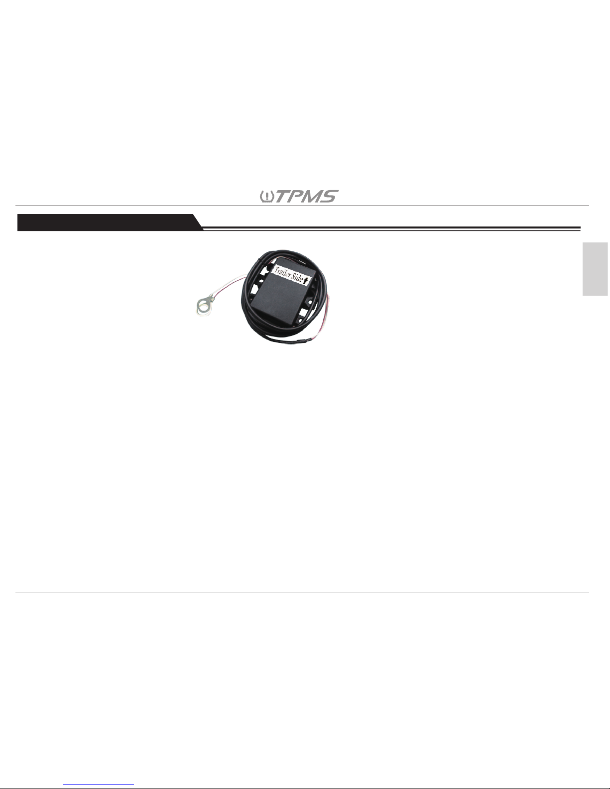
6. TPMS Repeater Installation
6.1 Repeater Appearance:
11
English
6.2 Installation Steps
The mounting location of the repeater will depend on the type of towable the TPMS will be installed
on. The repeater is designed to repeat the TPMS tire sensors’ RF signals to the receiver in the tow
vehicle. Ideally, to get better RF transmission between repeater and tire pressure sensors, the
repeater should be in an open space and no barriers between tire pressure sensors. Regarding the
repeater specification, please refer to the Chapter 3.3.
Page 13
12
English
7. Driving Mode Menu
When the receiver is turned on, it is in Driving Mode. The screen displays tire pressure, tire temperature
and vehicle battery voltage in sequence. The tire pressure, tire temperature and vehicle battery voltage
are updated on the monitor every 5 seconds.
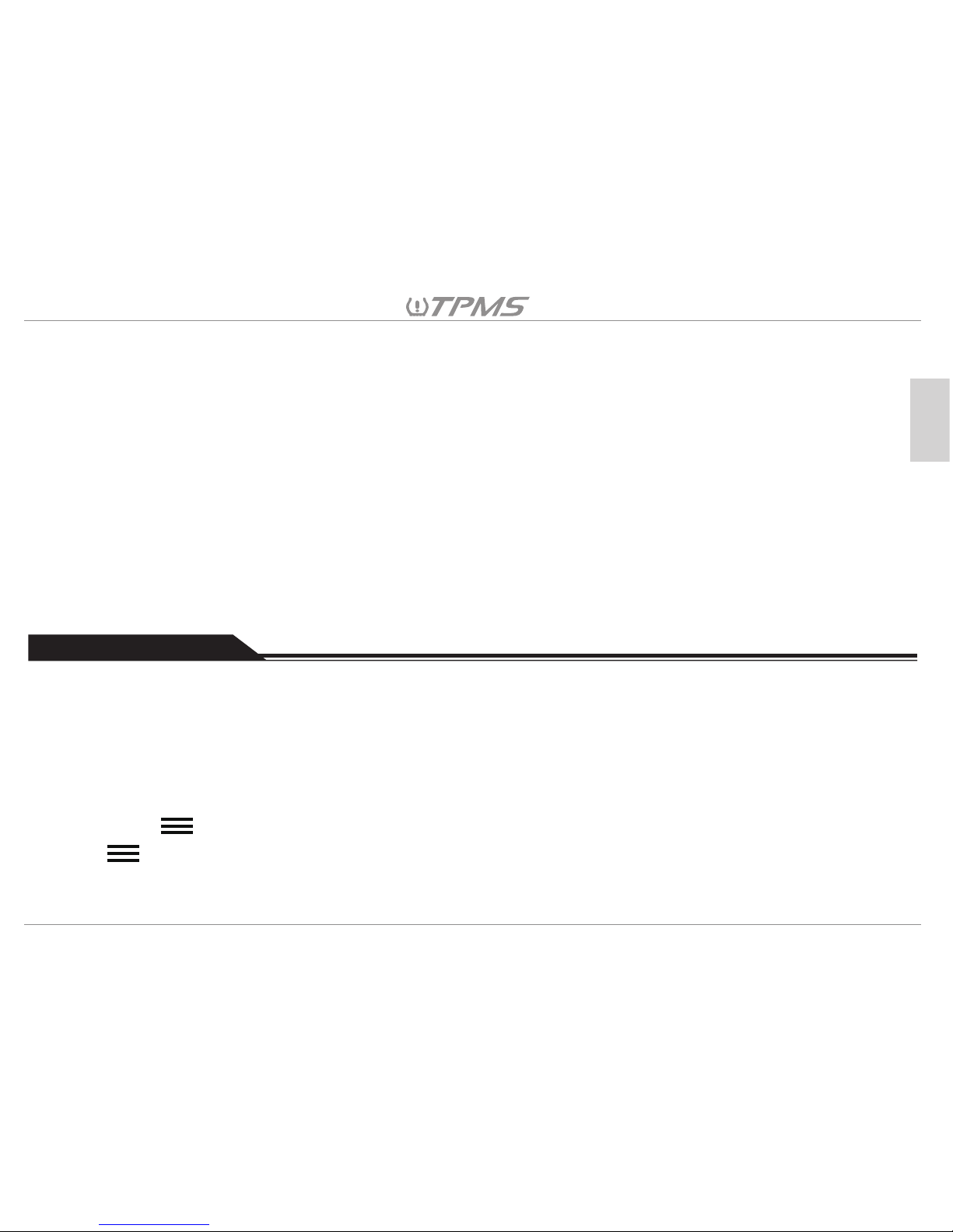
6.2.1 For travel, cargo or equipment trailers with a bumper pull A-frame hitch, place the repeater onto
the A-frame area of the trailer. Use self-tapping screws to fasten the repeater to one of the two
A-frame members with the “trailer side” black arrow facing the trailer and the power cable end
of the repeater facing the tow vehicle.
For 5th Wheels and gooseneck trailers select a location for the repeater near the house battery.
Use self-tapping screws to fasten the repeater with the “trailer side” black arrow facing the 5th
wheel or gooseneck trailer and the power cable end of the repeater facing the tow vehicle.
6.2.2 Mount the O-ring connectors on the repeater’s power cables to the proper trailer battery
terminals. The RED power cable is to be connected securely to the POSITIVE (+) battery
terminal. The BLACK power cable is to be connected to the NEGATIVE (-) battery terminal.
6.2.3 Use the cable ties to fasten the repeater power cable to the frame of the trailer or 5th wheel.
Avoid a loose repeater power cable by fastening the cable tightly to the frame.
7.1 Tire pressure Display: psi (Pressure units)
In the Driving Mode, the default value for tire pressure is set to 80 psi.
Press to show the pressure value only. When it shows tire pressure on the display, press
again to back to rotation display mode.
Page 14
OK
OK
7.3 Alarm Volume Adjustment
7.4 Mute Alarm
7.5 Screen OFF
7.2 Tire Temperature Display: °F (Temperature units)
In Driving Mode, the default value for tire temperature is set to 176 °F.
Press to show the pressure value only. When it shows tire pressure on the display, press
again to back to rotation display mode.
During the Driving Mode, press to adjust the volume.
Press to mute the alarm tone when alarm is going off. It will sound the alarm again if receiver power
is reset, or another alarm occurs in this wheel, or if the alarm occurs in the other wheels.
Hold for 3 seconds to turn off the screen, the receiver is still working in the background.
13
English
Pressure units
Default tire
pressure value
Temperature units
Default tire
pressure value
kPa
Psi
Bar
552 kPa
80 psi
5.5 Bar
°C 80°C
°F 176°F
Page 15
8. Setting Mode Menu
8.1 Vehicle Selection
7.6 Screen ON
Press any button to wake the LED display, the LED display will also light up when a tire alarm occurs.
14
English
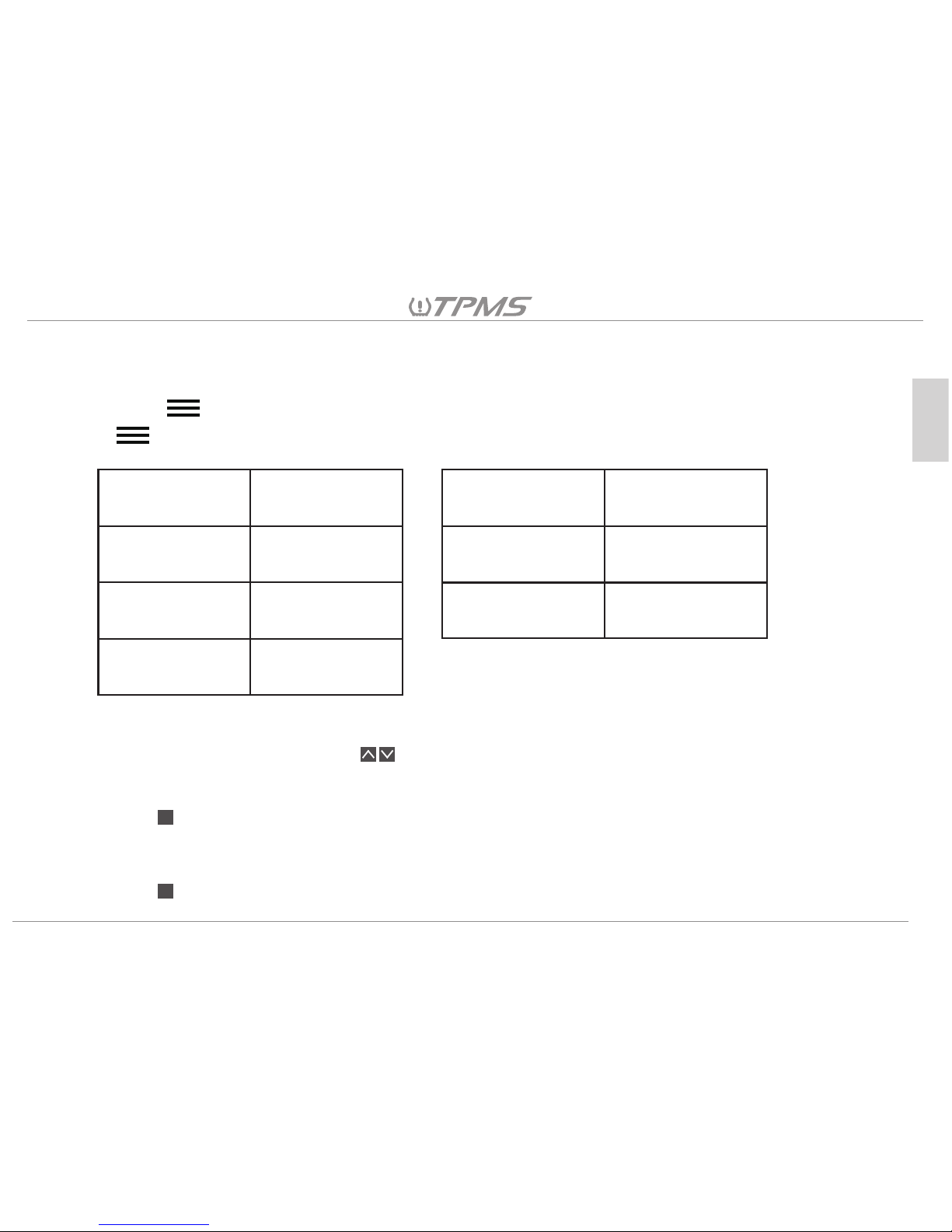
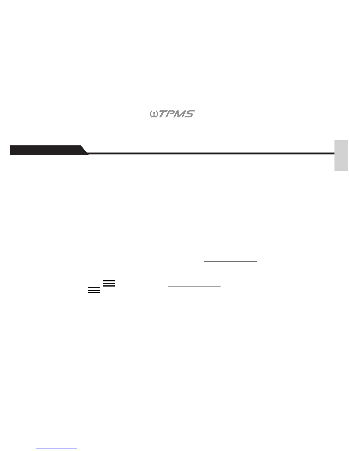
The receiver supports parameter settings for up to three vehicles, follow the procedure below to configure
the relative parameters for each vehicle.
1. Vehicle Selection
2. Setting Tire Pressure Unit
3. Setting Tire Temperature Unit
4. Setting the Number of Axles to Receiver
5. Setting Tire Position on the Receiver
6. Tire Sensor ID Pairing to the Receiver
The receiver can store the ID sensors of up to 3 vehicles. Vehicle Selection enables you to view,
set, or modify the TPMS settings of a specific vehicle. The first step is to select the vehicle that
you would like to setup.
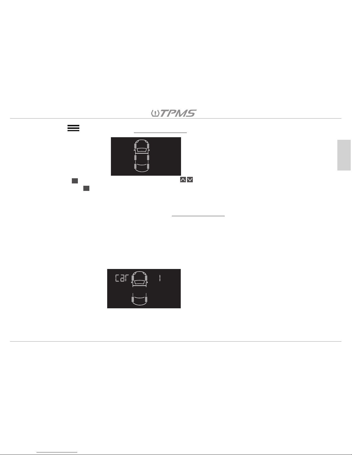
In Driving Mode, Hold for 3 seconds for Vehicle Selection.
At any time, hold for another 3 seconds to switch back to Driving Mode.
Page 16
15
English
OK
OK
8.1.1 Hold for 3 seconds for Vehicle Selection. The display as shown below will list “CAR 1”
to “CAR 3”.
8.1.2 Press , then “CAR 1” will blink. Press to select the vehicle you would setup,
then press to confirm, the receiver display will go to the TPMS setting mode and a short
beep will sound after a moment.
8.1.3 Please establish the TPMS parameter settings for this vehicle, starting with section 8.2. When
“CAR 1” settings are complete, go back to Vehicle Selection to repeat the setting procedure
for “CAR 2” and “CAR 3”.
8.1.4 If the user has two or three vehicle parameters already saved in the receiver, the receiver will
automatically connect with the closest paired vehicle, identify the sensor IDs for that vehicle,
and display the correct parameters in several minutes.
If there is a delay after changing the vehicle on the receiver, reset the receiver power in order
to get the corresponding vehicle TPMS data sooner.
CAR
CAR
CAR
1
2
3
Note:
User will have 60 seconds to make any changes, if no change is made within that period, the
receiver will beep for a long tone to warn that the settings have not been completed, and
display will return to Driving Mode.
Page 17
OK
OK
kPa
psi
Bar
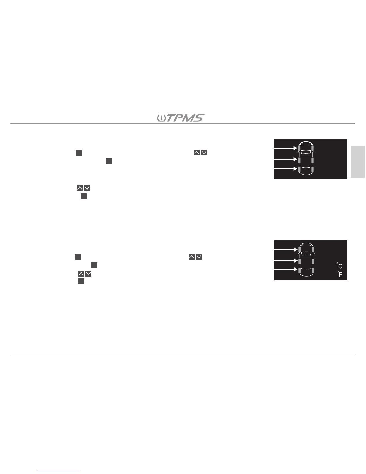
8.2.1 The screen will show “kPa” “psi” and “Bar” by default.
8.2.2 Press then the units will blink, now press to select the desired
unit, then press to confirm. You will have 60 seconds to make the
changes; if no change is made within that period, the receiver will beep
for a long tone to warn that the settings have not been completed.
8.2.3 Press to adjust the desired tire pressure value.
8.2.4 Press when the pressure is set to the desired value.
8.2.5 When you have completed the settings for all tires, you will hear three
short beeps, indicate that the changes have been saved successfully.
OK
16
English
8.3.1 The screen will show “ °C ” and “ °F ” by default.
8.3.2 Press then the units will blink, now press to select desired unit,
then press to confirm.
8.3.3 Press to adjust to the desired tire temperature value.
8.3.4 Press when the temperature is set to the desired value.
8.3.5 When you have completed the settings for all tires, you will hear three short beeps
indicating that the changes have been saved successfully.
OK
OK
OK
8.2 Setting Tire Pressure Units
8.3 Setting Tire Temperature Units
Page 18
OK
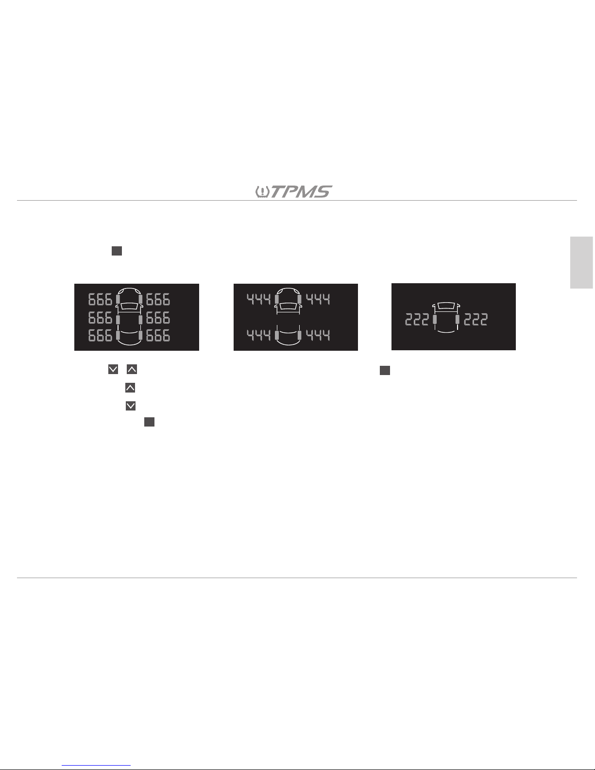
8.4 Setting the Number of Axles to Receiver
17
English
【4-Wheel】 【2-Wheel】【6-Wheel】
8.4.1 The screen will show the default axle number.
8.4.2 Press and the numbers will start flashing.
OK
OK
8.4.3 Press to select the number of axles, and then press to confirm.
8.4.4 Pressing will increase one axle.
8.4.5 Pressing will decrease one axle.
8.4.6 Finally, press and the receiver will beep, indicating that the setting has been saved.
The receiver will automatically go to the next setting function.
Page 19
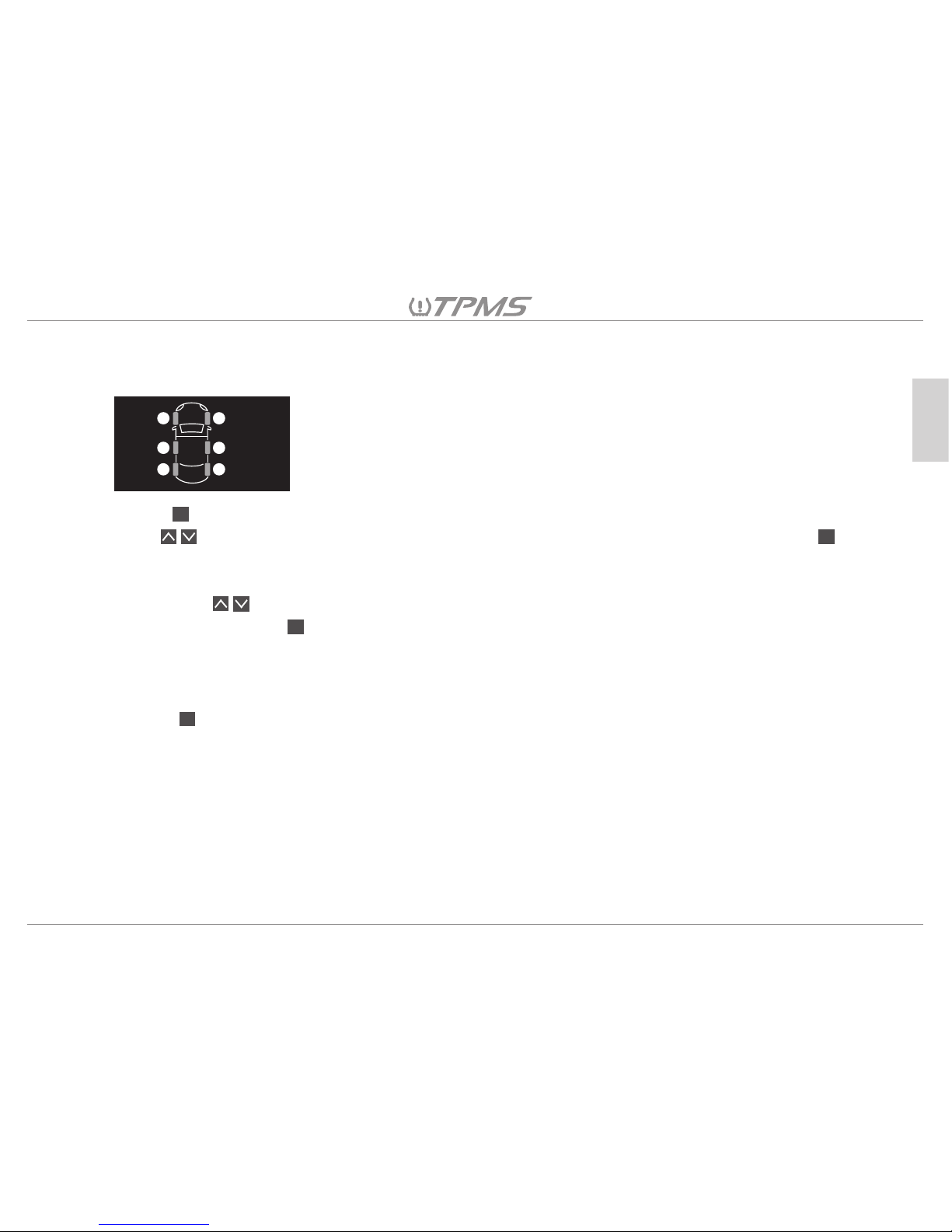
8.5 Setting the Tire Position on the Receiver
18
English
OK
OK
OK
OK
1
6
2
5
3
4
8.5.1 The numbered tire position for each tire sensor is shown on the receiver as pictured below.
8.5.2
8.5.3 Press to enter tire position rotation mode, digit 1 at the LF position will blink by default. Then
press to select the original tire position which needs to be changed and then press again,
and the digit at that selected position will turn green. If no change is made in this mode for 60
seconds, the receiver will beep to warn that setting has not been completed successfully.
8.5.4 Then press to select the new position to which you want to move the previously selected
position, and press to confirm, the digit at the new position will also turn green.
8.5.5 The digits at both exchanged positions will remain displayed in green for 3 seconds to show which
2 tires are exchanged. Then the chosen digits will automatically turn back to red.
8.5.6 Then the screen will show the new positions. If you need to exchange more than one pair of tires,
press to repeat the procedure.
Page 20
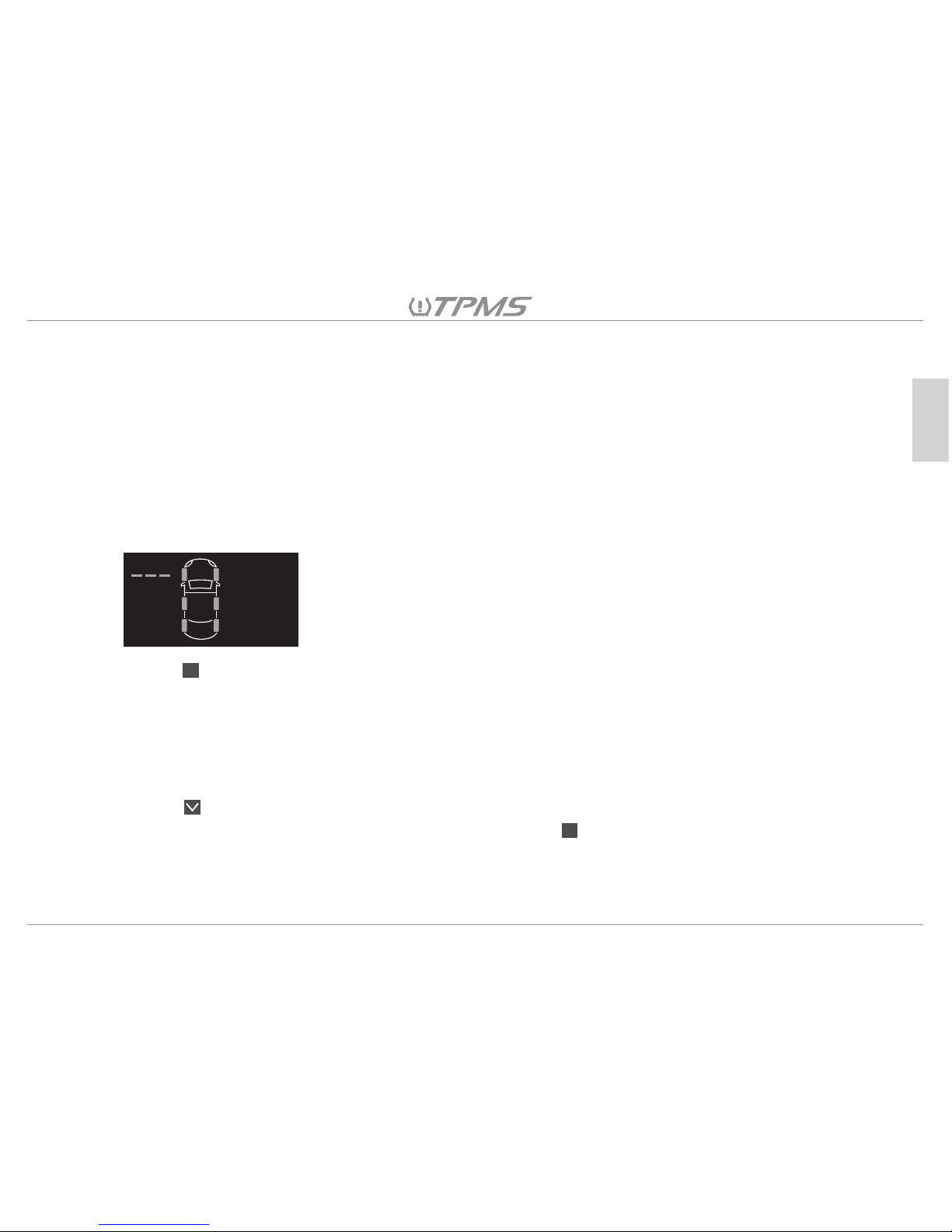
8.6 Tire Sensor ID Pairing to the Receiver
19
English
OK
OK
8.6.1 The screen will show “---” at the LF tire by default.
8.6.2
8.6.3 Press and the display “---”will start blinking, it is ready for Tire Sensor ID Pairing. Each tire will
have 120 seconds to complete the Tire Sensor ID Pairing after the blinking starts. The receiver will
emit a long beep and go back to the Tire Sensor ID Pairing Mode if it doesn’t receive any signal
from tire deflation within 120 seconds.
8.6.4 8.5.3 Deflate the corresponding tire, the receiver will beep when receiving the signal, the ID
Pairing is finished when the screen shows the sensor’s ID number.
8.6.5 Press for the next Tire Sensor ID Pairing.
After completing the Tire Sensor ID Pairing for all tires, press .
Remark: Trigger all sensors again after finishing the Tire Sensor ID Pairing, to see
if the tire data is shown at correct wheel location on the receiver display.
To pair the tire sensor ID to the receiver:
1. Start by moving the tow vehicle with the receiver unit installed close to the trailer or towable that has
the TPMS Sensors installed on the tires.
2. Disconnect the tow vehicle from the trailer electrically and physically if it is connected.
3. Move the tow vehicle with the receiver close to the wheels of the trailer or towable.
4. Enter the Settings Mode Menu and select “Tire Sensor ID Pairing” mode
5. Follow the procedure 8.5.1 through 8.5.4 for all Tire Sensors being paired to the Receiver.
Page 21

9. Abnormal Warning And Symbol Illustration
When the TPMS sensor transmits an abnormal signal to the receiver, a warning symbol will be displayed
and a continuous beep will be emitted as an alarm. The abnormal value is shown on the corresponding tire
on the receiver.
1. Warning of excessive high tire pressure indicates tire pressure has been risen to 50% or more of the
standard tire pressure value set by the user.
2. Warning of excessive low tire pressure indicates that the tire pressure has decreased by 20% or more
of the standard tire pressure value set by the user.
3. Warning of excessive tire temperature indicates that the tire temperature has
risen over the standard tire temperature value set by the user.
4. Climate change could be a factor for tire pressure change, please go to a service shop to do pressure
adjustments, to avoid the occurrence of false alarms. Be sure to maintain proper tire pressure in all of
your trailer or towable tires for the safest and most cost effective performance of your trailer or towable
tires.
20
English
Page 22
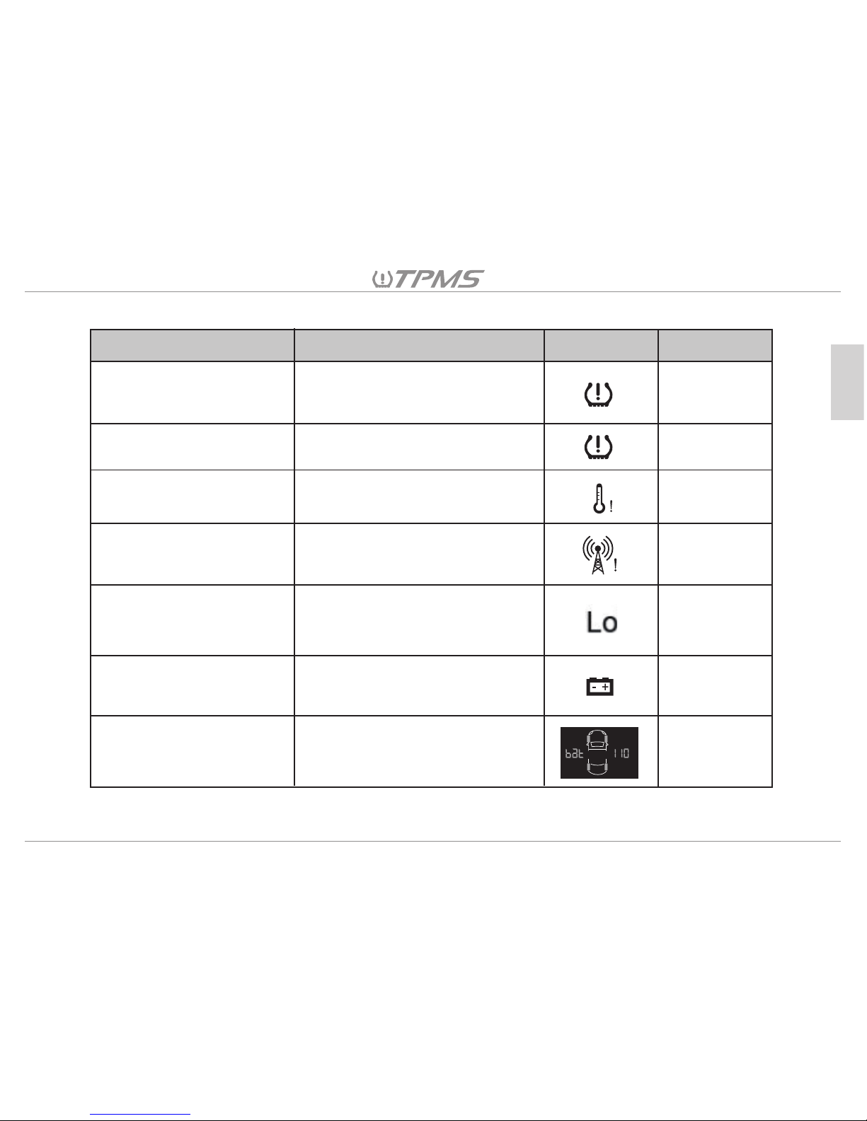
9.1 Alarm Display Symbols Key
21
English
Symbol
Definition
Alarm
Alarm Sound
Low Pressure
High Pressure
High Temperature
TPMS System Alarm
Low Battery Power on
the tow Vehicle (12V)
Low Battery Power on
the Trailer (12/24V)
P ≦ (0.8*standard pressure
valve) or ≦ 150 kPa, take the
bigger value
P ≧ (1.5*standard pressure
value)
T ≧ (standard
temperature value)
No signal receiving at least 10
minutes. Not activated when
vehicle is stopped.
Battery voltage at the tow
vehicle ≦ 11.5V
Battery voltage at the trailer ≦
11.5V or ≦23V
Beep
(per second)
Beep
(per second)
Beep
(per second)
Beep
(per second)
None
None
None
TPMS Sensor Low
Battery Power
Sensor battery is in low battery
power status
Page 23
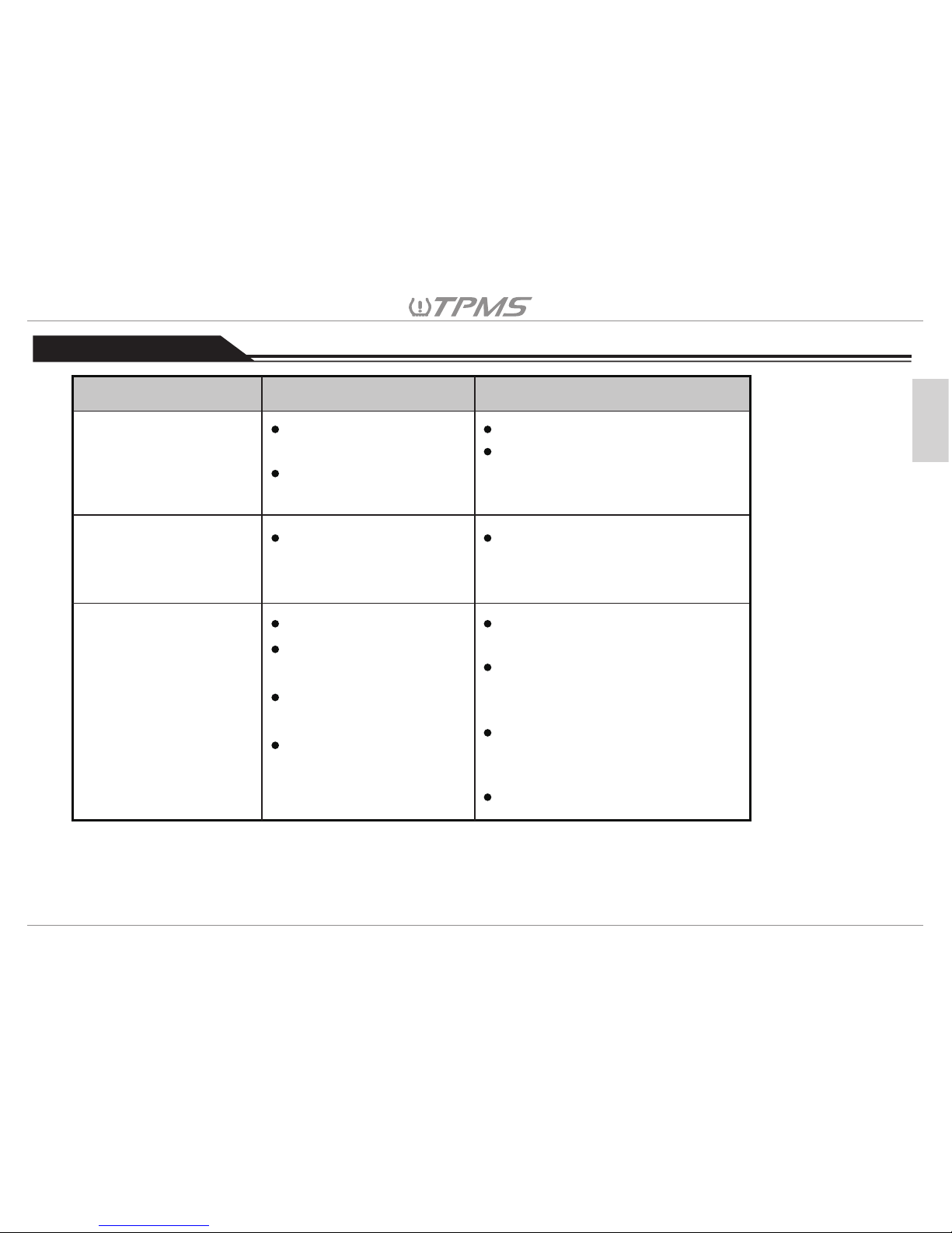
Issue probable causes Solution
Wireless signal
interference.
Tire air Pressure not
deflated enough
Remove receiver to other area.
Keep deflating the tires for
20~30 seconds
ID learn failed (TPMS
alarm with a long beep
in rapid deflation
learning setting)
Pressure anomaly
warning (TPMS alarm
with short beeps)
No signal received
(Screen shows the
pressure and the
temperature as “---“)
Low Tire Pressure
Signal interference.
Vehicle has stopped
or moves too slowly
Sensor is damaged or
low battery power
Please inflate the tires to the
correct pressure to prevent
an erroneous alarm
Move the tow vehicle away
from the current area.
Keep driving for a few
minutes, make tires rotate to
capture signals.
Go to a qualified service
shop for installation of a new
sensor on your wheel.
10. Troubleshooting
22
English
Repeater could be
damaged
Check the repeater
Page 24

11. Customer Service
23
English
All product support and warranty coverage are provided by the distributor that your product was
purchased in. Please contact your distributor who originally sold you the Tuson product.
Or contact us:
Toll Free: 800-968-8766
Email: [email protected]
Tuson RV Brakes, LLC
475 Bunker Court
Vernon Hills, IL 60061
www.tusonrvbrakes.com
Page 25

Limited Warranty
24
English
Tuson RV Brakes, LLC (Tuson) warrants the Tuson Tire Pressure Monitoring System (TPMS) to be free of
defects in material and workmanship for a period not to exceed TWO (2) years from the date of sale to the
original consumer, or to the first retail purchaser of a trailer on which the TPMS is installed. Original receipt(s)
or other acceptable proof of purchase should be retained by the customer for verification of warranty date.
THIS WARRANTY IS NOT TRANSFERABLE.
Tuson’s obligations under this warranty shall be limited to crediting the account of a direct buying distributor
or OEM trailer manufacturer, replacing or repairing the TPMS products which are determined by Tuson to be
defective in material or workmanship, within 60 days of receipt of such product by Tuson. Tuson reserves the
right to request the product be returned intact, freight prepaid, PRIOR to processing any claim for warranty.
Warranty claim must be received by Tuson within 30 days of the discovery of the alleged defect, or within 30
days of the expiration of the warranty, whichever is earlier. Covered repairs or replacements will be made at
Tuson’s expense. Shipment of replacement product or repaired product by Tuson will be via best available
ground shipment carrier. Shipments other than by best available ground shipment carrier, must be requested
in writing and must be paid for in advance by the customer. Returned product that is found not to be defective,
will be returned at sender’s expense.
Page 26
25
English
This Warranty shall not include any products which have been improperly installed, installed contrary to
installation instructions provided with the product, altered, tampered with or changed in any way, or utilized in
a manner not approved by Tuson. This Warranty shall not extend to any defects arising from abuse, misuse,
accident, improper wiring, or negligence of the installer or the consumer.
EXCEPT AS EXPRESSLY SET FORTH ABOVE, NO OTHER WARRANTY, EXPRESS OR IMPLIED, AT LAW
OR IN EQUITY, IS MADE BY TUSON CORPORATION IN RESPECT OF THE PRODUCT, INCLUDING
WITHOUT LIMITATION ANY IMPLIED WARRANTY OF MERCHANTABILITY, FITNESS FOR A
PARTICULAR PURPOSE OR ANY OTHER WARRANTY, AND ANY SUCH WARRANTIES ARE
EXPRESSLY DISCLAIMED.
IN NO EVENT SHALL TUSON BE LIABLE TO PURCHASER OR ANY THIRD PARTY FOR ANY LOST
PROFITS, CONSEQUENTIAL, EXEMPLARY, INDIRECT, PUNITIVE, INCIDENTAL, OR SPECIAL
DAMAGES OR COSTS (INCLUDING ATTORNEY FEES), OR LOSS OF GOOD WILL RESULTING FROM
ANY CLAIM (INCLUDING BUT NOT LIMITED TO ANY CAUSE OF ACTION SOUNDING IN CONTRACT,
TORT, NEGLIGENCE, STRICT LIABILITY OR PRODUCT LIABILITY) REGARDING THIS AGREEMENT,
EVEN IF THE COMPANY HAS BEEN ADVISED OF THE POSSIBILITY OF SUCH DAMAGES.
Some states do not allow the exclusion or limitation of implied warranties, incidental or consequential
damages, so the above limitations or exclusions may not apply to you. This Warranty gives you specific rights.
You may have other rights, which vary from state to state.
 Loading...