


USER’S GUIDE
FOR GRIDDLE PLATE

SPECIFICATION
NAME OF APPLIANCE SUPERTRON COMMERCIAL GRILL WITH SOLID GRILL PLATE
MODEL NO. GP-300, GP-600, GP-900, GP-1200
MANUFACTURED BY TU’S BROS PTY LTD
CERTIFICATE NO. 6235
Grill Plate Mild steel 300mm x 600mm with a 50mm grease trough x 15mm depth.
Gas Cocks Self latching 2 position “Off” and “On”. AGA App. No.2143
Grill Plate Flue Is provided into splashback from rear of grill plate
Gas Cocks As description under “Hot Plate”
Burner Type H shape cast iron ported burner
Mixing Tube Throat Venturi
Primary Air Circular on injector entry
Grill Ignition Is by means of a pilot light located adjacent to front left hand side of the
This appliance should be installed by authorized persons only and must be installed in accordance with AG601, 1995
refer Section 5.12.4 Catering Equipment and all Clauses to 5.12.4.5.
GAS PIPING SYSTEM
The gas inlet to the appliance is located at the rear of the unit. The connection point is 425mm above the floor facing
down. The gas point is in the centre of the unit.
The unit is supplied with a ¾" B.S.P. regulator – the installer must supply a ¾" B.S.P. gas cock to enable isolation of
the appliance for servicing. The unit must have at least a 1" B.S.P. (25mm) pipe up to the connection point, with a
minimum pressure of no less than 1.13 kpa inlet. A minimum appliance operating pressure is of no less than 0.1 kpa
with 60% of the appliance operating. The installer must use a manometer to check the pressure and test for leaks.
Test points are provided off the Regulator control and off the gas cock manifold. Alternatively a burner injector may
be used off the top burner and the manometer tube placed firmly over the injector after removing the burner.
The appliance must be installed to local Health Dept. and gas fitting regulations.
For test point pressure settings refer to data plate on the appliance.
For Service: call local gas agent or retailer in your region, or contact manufacturer for service information, should
appliance fail to operate correctly.
This application must be installed by an authorized person only
77 MAIN ROAD, CLAYTON SOUTH
VIC 3169 AUSTRALIA
General Description
A Ø50mm outlet from grease trough discharges into a grease collection
box located beneath grill plate and is easily removable from front of
control panel.
No. of Ports: 53 Perside x 7mm Centres
Size of Ports: 2.50mm
N.H.G.C.: NG 22MJ/h @ 1MPa, Injector 2.05mm
LPG 22MJ/h @ 2.75MPa, Injector 1.25mm
burner. Lighting of the pilot is by piezo ignition
INSTALLATION INSTRUCTIONS
(By Authotised Personnel Only)
ADDENDA
2

The installer must install the appliance to AG601, 1995 Section 5.12.4 and in accordance to local regulations.
Attention must be give to Section 5.12.4.4 and 5.12.4.5.
5.12.4.6 Commercial catering equipment on combustible surface, where equipment is installed on a combustible
surface it shall be protected by fire resistant material.
Fire resistant material specifications where appliances are to be installed in non combustible area, the installer must
refer to Ag601 and ensure the following side walls and bare walls have materials to the specifications referring to
standards A-S 1530.1 to be deemed not combustible and A-S 1530.3 have a zero(0) index for all of the following.
1. Ignitability
2. Spread of flame
3. Heat evolved
4. Smoke developed
N.B. The thermal resistance not less than 0.05 M/2o c/w but in no instance shall the material be of a thickness less
than 6mm.
OPERATION INSTRUCTION
These instructions must be read carefully prior to initial use and retained in a safe place.
Remove all protective covering on stainless steel panels.
GRILL BARBECUE (Lighting Procedure)
1. Press in gas cock knob to pilot symbol and stop (anti-clockwise).
2. Pilot is lit by a piezo press button adjacent to gas cock. Press button several times until pilot remains alight,
then turn gas cock to the desired by flame symbols for satisfactory flame. Pilot can be seen through viewing
hole.
3. Pre-heat barbecue for approximately 5-10 minutes before placing products on to the grids. This prevents
sticking of meat products, then reduce flame height to prevent undue flaring of the flame while barbecuing.
4. It is recommended that the appliance be kept clean to prevent excess fat build up.
Always empty fat collection tray daily.
Do not use any caustic base cleaning products. Damage to the appliance could result and void warranty.
SERVICING
(Must only be carried out by Authorised Personnel)
1. Service of combination gas controls must be carried out by an authorized person.
For gas service call authorized local gas agent or contact manugacturer for service information should appliance fail to
operate.
Phone: (613) 9543 9577
Fax: (613) 9544 1487
Or you call local Supertron Agent contact us.
CONVERSION INSTUCTIONS – NG TO LPG
1. Conversion bust not be carried out without consulting manufacturer or agent in the region.
2. (a) Remove N.G. injectors
(b) Remove N.B. regulator
(c) Replace pilot injector with L.P. type
(d) Set appliance operating pressure to 2.75 kpa
3
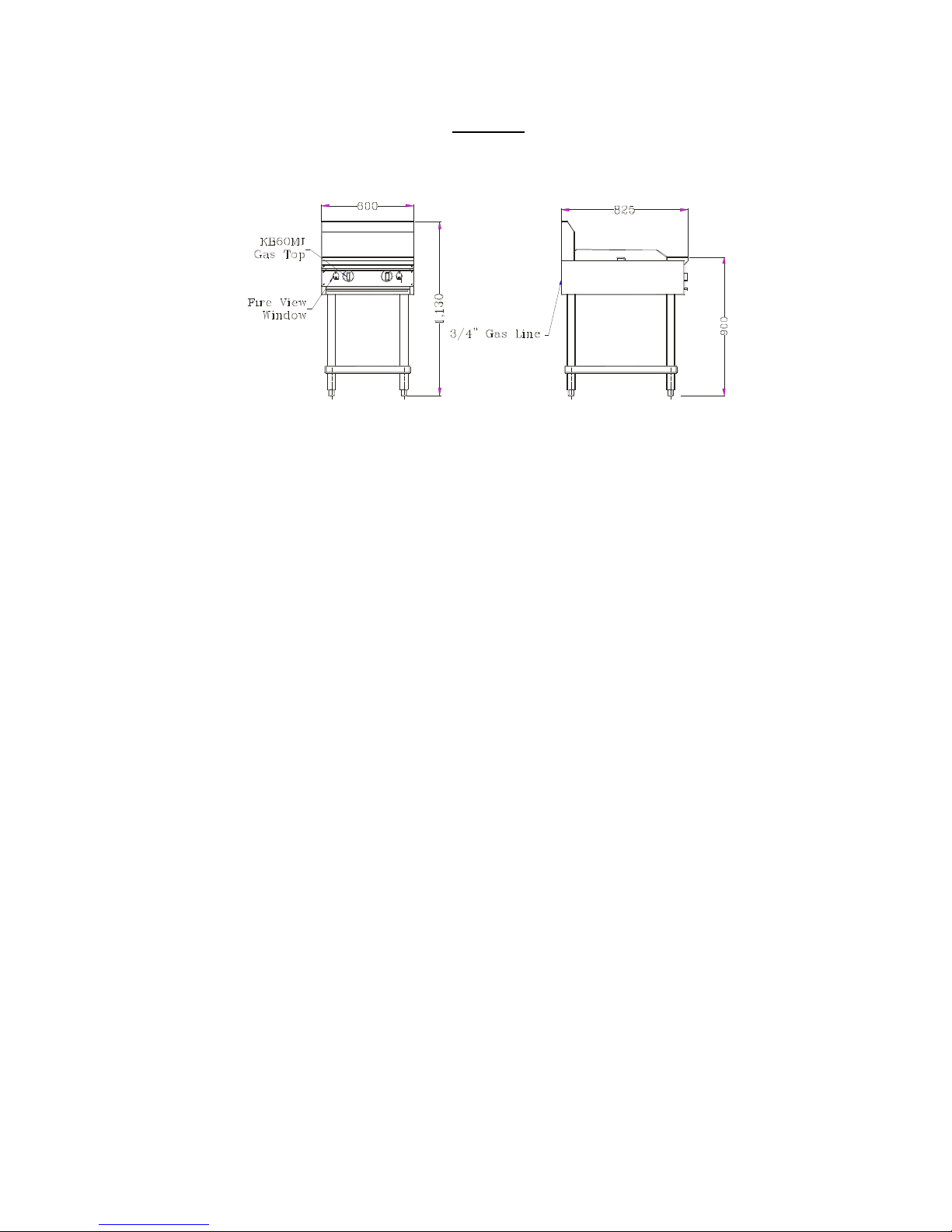
DIAGRAM
4
 Loading...