

Page 1
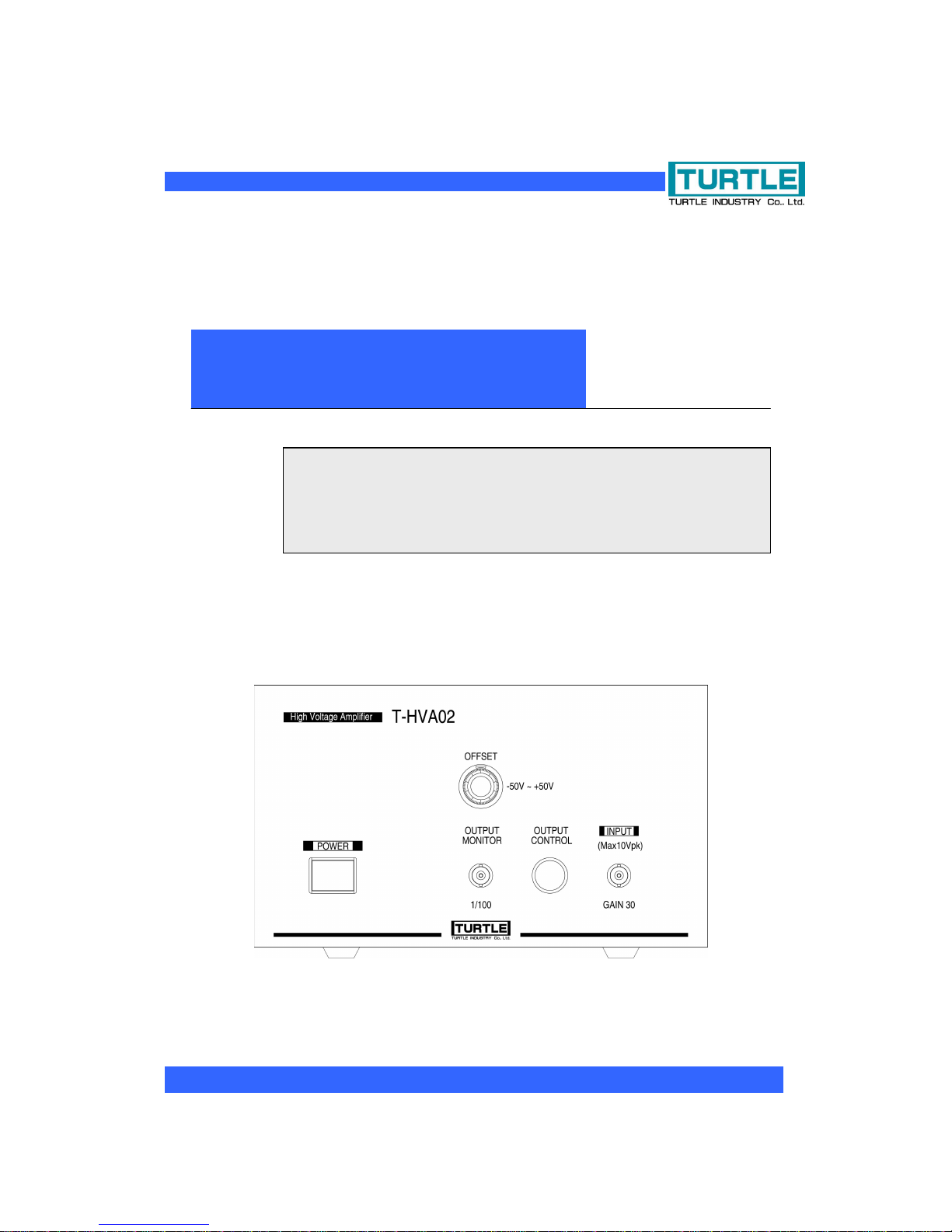
T-HVA02
High-speed High-voltage Amplifier
Operating Instruction Manual
Page 2
Instruction Manual for T-HVA02
1
©2000 Turtle Industry Co., Ltd. All rights reserved.
Copying or modifying the document is prohibited without the permission of Turtle Industry
Co., Ltd.
Warnings and Cautions (Ensure to Read Before Use)
This operating instructions manual describes how to prevent any physical injury or
damage to property and ensures safe use of the product.
The indications and labels used in this document have the following meanings. Please
ensure you have carefully read and understand the content before reading the main text.
Any failure to observe this warning or mishandling
the product could result in death or severe injury.
Any failure to observe this caution or mishandling
the product could result in physical injury or
damage to property.
(1) The specifications of the product and content of this operating instructions manual are both subject
to change without prior notice.
(2) No individual parts or all of the product or this operating instructions manual can be reprinted
without prior permission.
(3) This operating instructions manual was created to be thorough but if anything is unclear or requires
correction please contact the Service Support Section of Turtle Industry.
(4) We will bear no responsibility for any claims for losses or lost earnings allegedly due to operation
of the product, notwithstanding the above.
(5) The product was not intended to be incorporated in or to control any facilities or equipment that
could involve human lives or that require a high level of reliability. We will bear absolutely no
responsibility for any fatal accidents or damage to property that occur because the product was
used in any such facilities or equipment.
(6) If the product and software fall under the category of being strategic goods (or services) according
to the provisions of the Foreign Exchange and Foreign Trade Control Law an export permit issued
by the Japanese government will be required in exporting the product abroad.
©2004 Turtle Industry Co., Ltd. All rights reserved.
Copying or modifying this document is prohibited without prior permission from Turtle Industry Co., Ltd.
Any names of companies or products used in this document are the trademark or registered trademark of
the company concerned.
Warning
Caution
Page 3
Instruction Manual for T-HVA02
2
Warnings and Cautions on Use
Ensure to cut off all the power supply of any equipment before connecting or
removing it. Failure to do so could pose the hazard of an electric shock
depending on the equipment used.
Ensure to observe the indicated range of voltage and current in the
specifications with the terminals. Failure to do so could result in overheating and
fire or electricity leaking.
Do not use the product anywhere it could be exposed to water or chemicals.
Failure to do so could result in fire or other type of disaster.
Do not use the product anywhere inflammable gases could be present. Failure
to do so could result in fire or explosion.
Do not install the product anywhere unstable or it could fall over and result in
physical injury.
If any smoke or abnormal odors get generated ensure to immediately cease use
of the product. Remove the power supply cable and consult our Service Support
Section.
Warning
Caution
Page 4

Instruction Manual for T-HVA02
3
1. Introduction......................................................................................................................... 4
1.1 Product Outline............................................................................................................. 4
1.2 Product Structure.......................................................................................................... 4
2. Names of Each Part........................................................................................................... 5
2.1 Front ............................................................................................................................ 5
2.2 Rear.............................................................................................................................. 6
3. Description of Each Part..................................................................................................... 8
3.1 Input Terminal (INPUT)................................................................................................. 8
3.2 Output Terminal (OUTPUT).......................................................................................... 8
3.3 Output Switch (OUTPUT CONTROL) .......................................................................... 8
3.4 Offset Adjustment (OFFSET)........................................................................................ 9
3.5 Output Monitor Terminal (OUTPUT MONITOR)...........................................................9
3.6 GND Terminal (GND)....................................................................................................9
3.7 Fuse (FUSE)................................................................................................................. 9
3.8 AC Inlet (95-105V AC).................................................................................................. 9
4. Important Notes on Use...................................................................................................10
5. Other..................................................................................................................................11
5.1 Limited Warranty..........................................................................................................11
5.2 Contact Information.....................................................................................................11
6. Specifications ..................................................................................................................13
6.1 Summary of Specifications......................................................................................... 13
6.2 Outline of Dimensions ............................................................................................... 14
Page 5

Instruction Manual for T-HVA02
4
1. Introduction
Thank you very much for purchasing the High-speed High-voltage Amplifier T-HVA02 made
by Turtle Industry Co., Ltd.
The document describes use of the product, including its special features, how to use it,
handling instructions, and other information related to the product.
To use the product correctly you will need to be familiar with electric circuits because of the
special nature of the product. Any wrong usage or mishandling could result in not only
damage to the product but also lead to a serious accident. Please ensure you have
thoroughly read and understood this document in ensuring correct use of the product.
1.1 Product Outline
This product is a high-speed direct current amplifier with an output voltage of 600 Vpp. It has
a slew rate of 400V/µs and thus an excellent response to large amplitudes. The maximum
output current is 100 mA, thus incorporating a sufficient margin for the product to be used for
various purposes.
The offset adjustment is equipped with a fine-tuning dial function, thus supporting an output
offset of ±50 V.
1.2 Product Structure
The product package contains:
(1) Main Body of T-HVA02
(2) Operating Instructions Manual
(3) AC Cable
* If any of the above is missing ensure to contact our Service Support Section. (Refer to
page 11 for contact information.)
Page 6
Instruction Manual for T-HVA02
5
2. Names of Each Part
2.1 Front
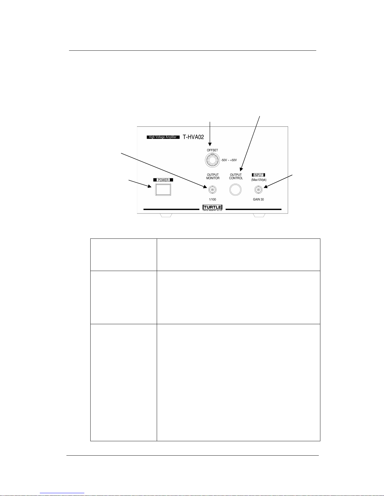
Power Supply Switch A push button switch used to supply power to the
amplifier.
When turned on the switch will light up in green.
Input Terminal Used to input signals. The input signals will be output
after the voltage has been amplified thirty times. Ensure
that a total of the output voltage from the input signals and
any signals due to the offset adjustment do not exceed
the range of ±300 V.
Output Switch A push button switch used to switch the output signals on
and off.
Lighting up red means signals are being output. Even
when the output has been set to off the built-in
high-voltage amplifier is still running, thus allowing it to be
monitored through the output monitor.
[Caution]
Even when the output is off about 1µA is being leaked.
Even when the output is off a capacitance of about 50 pF
is present between the output of the built-in amplifier and
the output terminal.
Power Supply Switch
Output Switch
Offset Adjustment
Output Monitor Terminal
Input Terminal
Page 7
Instruction Manual for T-HVA02
6
Offset Adjustment Direct current voltage within the range of approx. ±50 V
can be added to the output voltage.
Output Monitor
Terminal
A monitor terminal for the output terminal. About 1/100
voltage of the output voltage will be output. The effective
bandwidth is less than 1 MHz.
To prevent the equipment from being damaged due to a
sudden voltage surge ensure to set the output switch to off before supplying any power.
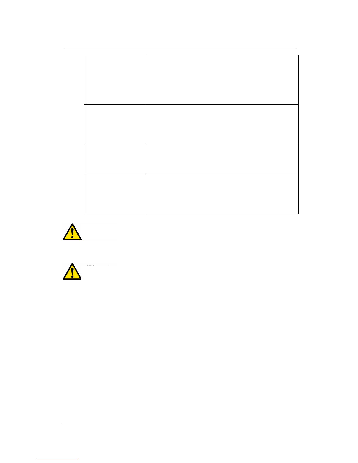
2.2 Rear
Fuse
Voltage Output GND Terminal AC Inlet
Caution
Page 8
Instruction Manual for T-HVA02
7
To avoid any hazardous situations make the connection after
ensuring there is no chance of a human body coming in contact with the high voltage side of
the voltage output (central terminal of BNC).
To avoid any hazardous situations ensure to ground it using a
GND terminal or AC inlet earth terminal.
Output Terminal This is where
signals are output with converted and
amplified voltage. High voltage is output here, thus
making touching the terminal in the center very
dangerous. Before connecting ensure sure to cut off the
power supply.
GND Terminal Connects to the internal signal GND. The internal signal
GND, the earth terminal for the AC inlet, and the case are
all common. To avoid any hazardous situations ensure to
ground it using a GND terminal or AC connection.
Fuse The fuse. If the fuse blows ensure to replace it with a 3A
time-delay (resistant to rush current) type fuse. When
replacing remove the AC input for greater safety.
AC Inlet Use with the accompanying AC cable to connect to an
AC100V power supply. Ensure to ground it for greater
safety. If it cannot be grounded at an outlet make an earth
connection using a GND terminal.
Warning
Warning
Page 9

Instruction Manual for T-HVA02
8
3. Description of Each Part
3.1 Input Terminal (INPUT)
The terminal is used to input the signals to be amplified. The input signals here will be
amplified 30 times and then output at the output terminal. A BNC connector is used here.
Ensure that a total of 30 times the input voltage that passes through the terminal and the
amount of the offset adjustment does not exceed ±300 V.
* The INPUT shield and OUTPUT shield sides have common potentiality (electrically
connected).
* The INPUT shield side and case have common potentiality (electrically connected).
* The input resistance at the input terminal is approx. 1 MΩ.
3.2 Output Terminal (OUTPUT)
The terminal is used to output the amplified voltage. The centerline is of high voltage, thus
making it very dangerous. When routing the output signal cables ensure to eliminate any
possibility of the human body easily coming in contact with the centerline.
The operating output voltage is from -300V to +300V.
* The OUTPUT shield side and INPUT shield side have common potentiality (electrically
connected).
* The INPUT shield side and case have common potentiality (electrically connected).
3.3 Output Switch (OUTPUT CONTROL)
This switch is used to enable or disable any voltage being output to the output terminal.
Pushing the switch will light up the button in red and enable output. If it does not light up the
output is off.
Even when the output is off ensure to keep the following in mind:
a) About 1µA of current will be leaking.
b) The internal amplifier and output terminal are connected with a capacitance of
about 50 pF. Depending on the frequency of the signals and the load some signal
voltage may get generated at the output. Even when the output is off ensure to
never touch the output central signal line.
To avoid hazardous situation ensure to never touch the output
terminal while power is being supplied, even if the output switch is turned off.
Warning
Page 10

Instruction Manual for T-HVA02
9
3.4 Offset Adjustment (OFFSET)
A direct current voltage from -50 V to +50 V can be added to the output voltage.
A potentiometer with 10 rotations gets utilized here. It can be adjusted toward being positive
by turning it clockwise and toward negative by turning it counterclockwise. Ensure that the
total of 30 times the input voltage passing through the terminal and the amount of the offset
adjustment does not exceed ±300 V.
3.5 Output Monitor Terminal (OUTPUT MONITOR)
The monitor terminal for the output amplifier, which monitors the output terminal of the
internal amplifier and hence will be output when the output switch is set to off.
3.6 GND Terminal (GND)
The signal GND, the case, and the earthing wire of the AC cable are all common. Ground it
using the earth wire of the AC cable or this terminal.
3.7 Fuse (FUSE)
Use an AC125V (or more) - 3A time delay fuse (resistant to rush current).
Size: φ6.3 x 30 mm
3.8 AC Inlet (95-105V AC)
Supply AC100 V (50/60 Hz) power using the accompanying AC cable.
Page 11

Instruction Manual for T-HVA02
10
4. Important Notes on Use
The internal amplifier has an overheating protection circuit. Once the temperature of the
output IC exceeds the threshold value the output will be turned off. If the protection has
been activated ensure to turn off the power supply and review the load on the product
or ambient temperature.
* The overheat protection will not recover until the power supply has been cut off.
Also has an overcurrent protection circuit. The protection circuit will be active while the
rated output current is flowing. If the protection does get activated ensure to review the
load on the product and signals.
Switching the output switch from off to on while the output level is high may activate the
overcurrent protection circuit and the output may not therefore be correct. Ensure to
turn the output switch on first and then increase the signal voltage.
Page 12

Instruction Manual for T-HVA02
11
5. Other
5.1 Limited Warranty
The Turtle Industry (Turtle-Ind) warrants each product of its manufacture to be free
from defects in material and workmanship subject to the following terms and conditions.
The warranty is effective for half a year after the shipment by Turtle-Ind to the original
purchaser.
The obligation of Turtle-Ind under the warranty is limited to servicing or adjusting any
product returned to the head office of Turtle-Ind for this purpose and to replacing any
defective part thereof. Such product must be returned by the original purchaser,
transportation charges prepaid, with sufficient and detailed proof in writing of the
defect. If the fault has been caused by misuse or abnormal conditions of operation,
repairs must be paid for. Prior to repair, in this instance, a quotation will be submitted.
Service or shipping information will be notified depending on the difficulty encountered.
Model and serial numbers must be supplied by user. Batteries are specifically excluded
under warranty.
Turtle-Ind shall not be liable for any injury to persons or property or for expenses
incurred by the use of any Turtle-Ind product.
5.2 Contact Information
If you have any problems with the equipment or any questions please contact us at the
following.
We will investigate the problem and then get back to you.
When making an inquiry ensure to provide as much information as possible, including the
operating environment.
Page 13
Instruction Manual for T-HVA02
12
Turtle Industry Co., Ltd.
~ Support Service Section,
Technical Division, Technical Department ~
1-12-4, Nishineminami, Tsuchiura-shi,
Ibaraki, Japan, 300-0842
Page 14
Instruction Manual for T-HVA02
13
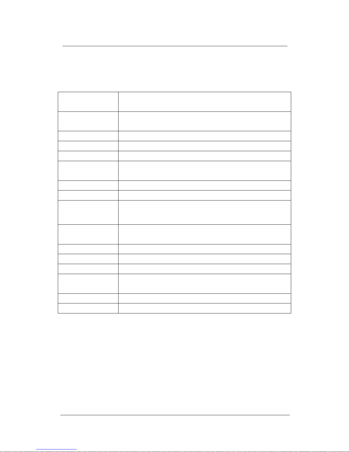
6. Specifications
6.1 Summary of Specifications
Maximum Output
Voltage
±300 Vpk
Maximum Output
Current
±100 mA
Output Resistance 18 Ω (standard), 35 Ω (maximum)
Monitor Output 1/100 of Output Voltage
Slew Rate 400 V/µs or more
Minimum Load
Resistance
2 kΩ (resistance load)
Input Resistance 1 MΩ
Gain 30 times (29.5 dB, fixed) ±3%
Output Offset
Adjustment
approx. ±50 V
Small Signal
Frequency Property
DC ~ 2 MHz (±3 dB, no load of 15 Vpp)
Power Supply Voltage AC100 V ± 5 V
Consumed Current approx. 250 mA (AC100 V, output 0 V)
Fuse 3A time-delay type
Operating
Temperature Range
5 ~ 35 C
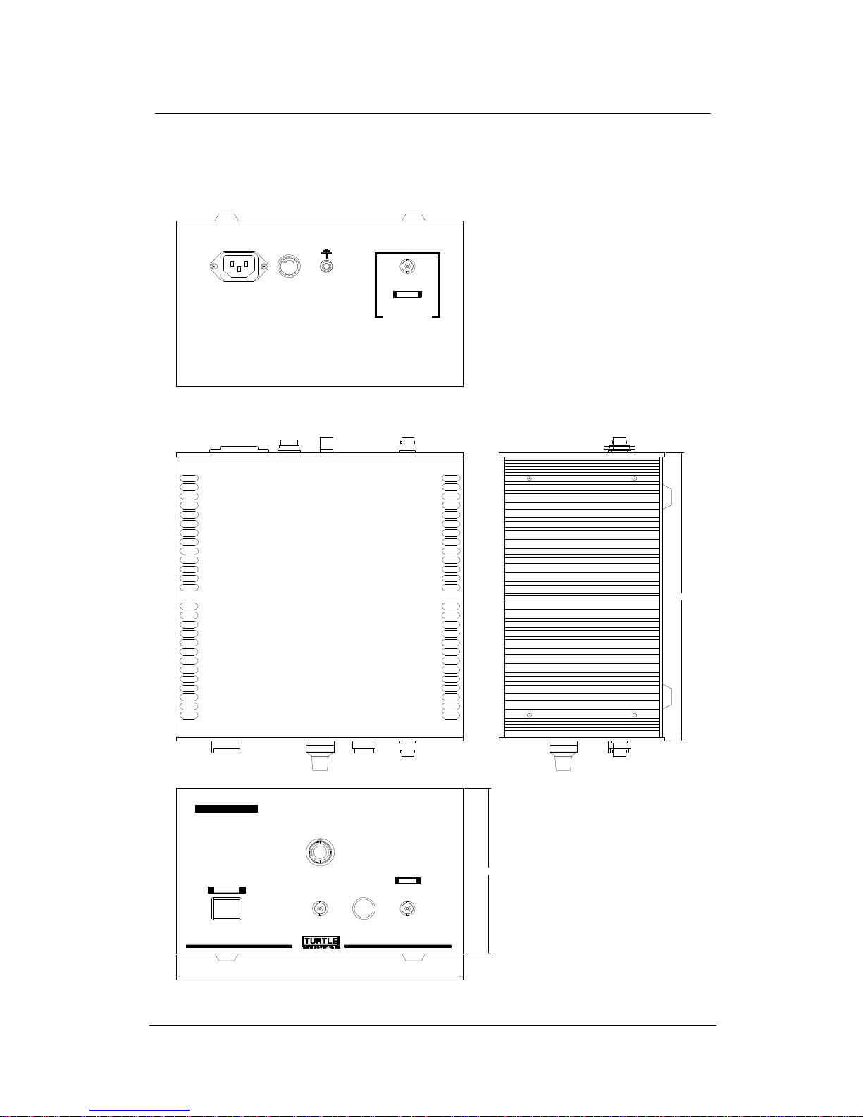
Dimensions 132.5 (H) x 230 (W) x 231 (D) mm (protrusion not included)
Weight approx. 6 kg (accessories such as AC cable not included)
Page 15
Instruction Manual for T-HVA02
14
6.2 Outline of Dimensions
AC100V
POWER
INPUTOUTPUT
MONITOR
OFFSET
-50V ~ +50V
OUTPUT
CONTROL
1/100 GAIN 30
T-HVA02
High Voltage Amplifier
(Max10Vpk)
95V~105V AC
FUSE
TIME LAG
3A
OUTPUT
(Max400Vpk)
DANGER!
High Voltage
FUSE
231
230
132.5
Page 16

Instruction Manual for T-HVA02
15
Instruction Manual for T-HVA02
Date of Issue: April 2012, Second Edition
Issued by: Turtle Industry Co., Ltd.
Edited by: Turtle Industry Co., Ltd.
c2011 Turtle Industry Co., Ltd
 Loading...