

Turris Omnia RTROM01 User Manual
User Manual
Before starting up the device, please read this manual carefully,
particularly the router installation instructions and safety information.
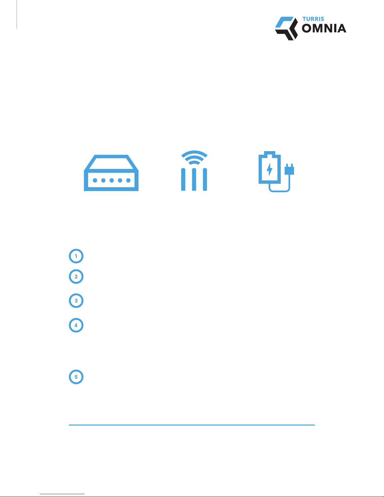
PACKAGE CONTENTS*
ROUTER INSTALLATION
Connect the antennas to the connectors located on the back of the router.
Connect your computer and the router with an Ethernet cable. Use one of the connectors labelled LAN0 to LAN4 on the router.
Plug the Ethernet cable from your modem or other device given to you by your internet service
provider into the WAN connector.
Plug the power cable into the router.
Important: Make sure that you are using a power adapter labelled Turris Omnia (12 V, 3.33 A).
When booting up, the device gradually lights up the indicator LEDs on the front panel. This is a
standard part of the start-up sequence.
Wait about one minute (until the router assigns an IP address), type h tt p:// 192 .168 .1.1 into your
internet browser and follow the instructions of the setup wizard.
The current version of the manual is available at
https://omnia.turris.cz/user_manual.
For more information go to
https://omnia.turris.cz/en.
* This manual is valid for standard packaging router Turris Omnia. If you have any other version (or additional accessories), please visit
https://omnia.turris.cz/user_manual for more information.
Router Turris Omnia 3× antenna Power adapter
and cable
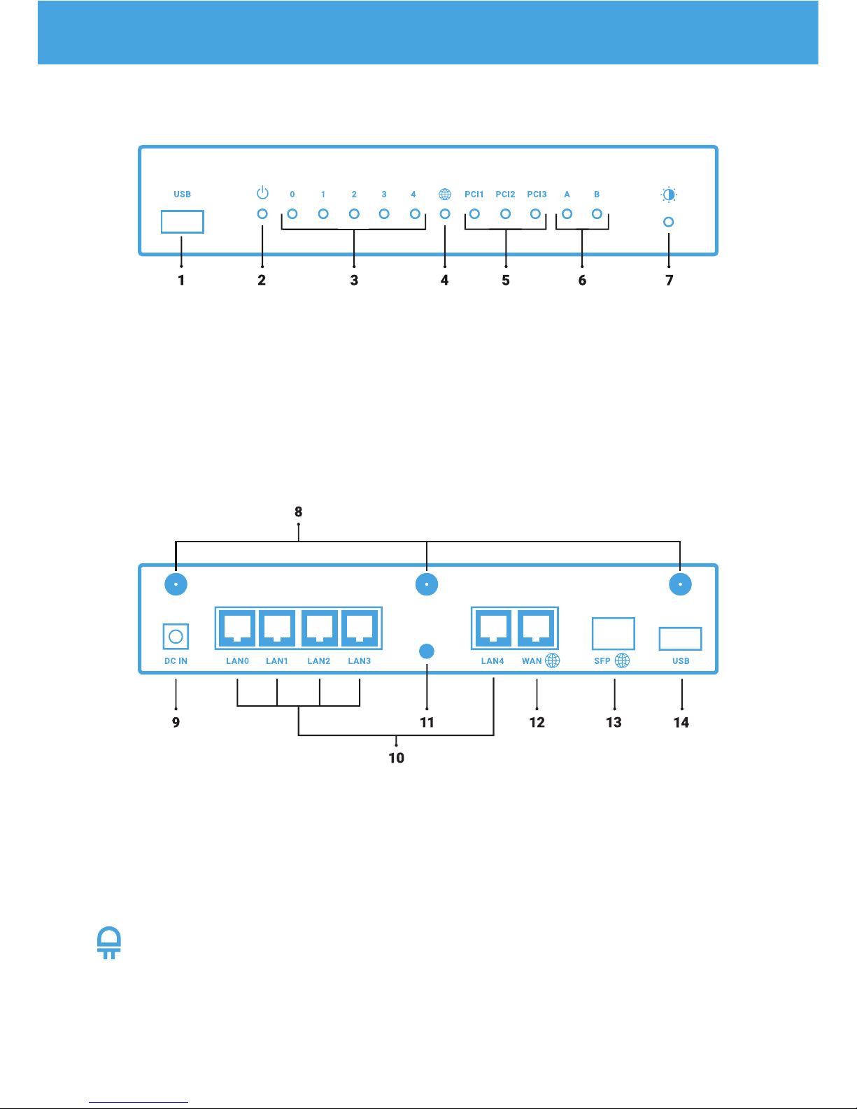
FRONT PANEL
REAR PANEL
CONFIGURING LED INDICATORS
You can control the brightness of the indicator LEDs on the front panel using button (no. 7) located on the front of
the device. Pressing the button reduces the brightness in eight steps until the LEDs turn off completely. Pressing the
button again resets the brightness back to the maximum value. In some cases, disconnecting the device from the
power source and then turning it on again may reset the default brightness setting to the maximum.
1) USB 3.0
2) Power indicator
3) LAN interface activity indicator
4) WAN interface activity indicator
5) Expansion card activity indicator (WiFi)
Factor y settings: • PCI 1 – 5 GHz WiFi
• PCI 2 – 2.4 GHz WiFi
• PCI 3 – Not used
6) User indicators
7) Button to adjust the brightness of the LEDs
8) WiFi antenna connectors
9) Power connector
10) LAN interface connectors
11) RESET button
12) WAN interface connector
13) SFP interface connector
14) USB 3.0
DESCRIPTION OF THE CONNECTORS AND CONTROLS
 Loading...