

Turnstyle Pillar Mount, Pillar Ground Instruction Manual

WWW.TURNSTYLEGATES.COM Foreign & Domestic Patents Issued & Pending! 1-800-548-2212 1
Instruction Manual
The Armless Gate Opener ™
Steel Model Pillar & Ground Mount Operators

WWW.TURNSTYLEGATES.COM Foreign & Domestic Patents Issued & Pending! 1-800-548-2212 2
Table Of Contents
I. SAFETY CONSIDERATIONS............................................................3
Installation Safety for Automatic Gates......................3
Operational Safety for Automatic Gates.....................3
II. INTRODUCTION...............................................................................4
III. APPLICATIONS.................................................................................4
IV. PRE-INSTALLATION CONSIDERATIONS.........................................5
Welded/Integrated Gates............................................5
V. TOOLS / ITEMS NEEDED FOR INSTALLATION................................5
VI. PRE-INSTALLATION MEASUREMENTS...........................................6
VII. INSTALLATIONS................................................................................7
A. Pillar Mount..................................................................7
B. Ground Mount............................................................10
VIII. BRACKETS......................................................................................12
IX. ELECTRONICS................................................................................14
Control Panel.............................................................14
Wiring Terminal Functions..........................................15
Wiring Instructions.....................................................16
Adjustments...............................................................16
Auto-Close & Locks...................................................17
X. OPTIONAL EQUIPMENT INSTALLATION.........................................18
XI. TROUBLESHOOTING THE OPERATOR AND ACCESSORIES........19
XII. OUR PROMISE TO YOU..................................................................20
XIII. WARRANTY / IDENTIFICATION LABEL...........................................20
www.turnstylegates.com
www.turnstylegates.blogspot.com
Contact our o!ce:
Toll Free: 1-800-548-2212
Direct: 1-843-527-3530

WWW.TURNSTYLEGATES.COM Foreign & Domestic Patents Issued & Pending! 1-800-548-2212 3
! Turnstyle Enterprises wishes to emphasize that safety always comes first. It is of the utmost importance that the
correct installation guidelines be followed during assembly and that all people and objects be kept clear of potential
entrapment areas. Please read the following safety guidelines before performing your installation.
Before beginning your installation, make sure that your gates and gate opener installation comply with applicable local codes.
Installation Safety for Automatic Gates
a. Install the gate opener only when:
1. The operator is appropriate for the construction of the gate and the usage Class of the gate.
2. All exposed pinch points are eliminated or guarded.
b. The operator is intended for installation only on gates used for vehicles. Pedestrians must be supplied with a separate access
opening. The pedestrian access opening shall be designed to promote pedestrian usage. Locate the gate such that persons will
not come in contact with the vehicular gate during the entire path of travel of the vehicular gate.
c. The gate must be installed in a location so that enough clearance is supplied between the gate and adjacent structures when
opening and closing to reduce risk of entrapment. Swinging gates shall not open into public access areas.
d. The gate must be properly installed and work freely in both directions prior to the final adjustment of the operator and connection to
the power supply.
e. Controls intended for user activation must be located at least six feet (6’) away from any moving part of the gate and where the
user is prevented from reaching over, under, around or through the gate to operate the controls. Outdoor or easily accessible
controls shall have a security feature to prevent unauthorized use.
f. The Stop and/or Reset button must be located in the line-of-sight of the gate. Activation of the reset control shall not cause the
operator to start.
g. A minimum of two (2) WARNING SIGNS shall be installed, one on each side of the gate where easily visible. [Warning signs have
been supplied with the Turnstyle operator.]
[FOR USERS AND INSTALLERS UTILIZING TYPE “D” ENTRAPMENT PROTECTION, NON-CONTACT SENSORS AND
CONTACT SENSORS, THE FOLLOWING ADDITIONAL SAFETY CONCERNS APPLY. MORE DETAILED TREATMENT MAY
BE FOUND IN UNDERWRITERS LABORATORIES SPECIFICATION 325 (UL 325).]
a. For gate operators utilizing Type D [entrapment] protection:
1. The gate operator controls must be placed so that the user has full view of the gate area when the gate is moving.
2. An automatic closing device (such as a timer, loop sensor, or similar device) shall not be employed, and
3. No other activation device shall be connected.
b. For gate operators utilizing non-contact sensor, refer to UL 325, Section 31.1.1:
1. See instructions on the placement of non-contact sensors for each type of application.
2. Care shall be exercised to reduce the risk of nuisance tripping, such as when a vehicle, trips the sensor while the gate is
moving, and
3. One or more non-contact sensors shall be located where the risk of entrapment or obstruction exists, such as the
perimeter reachable by a moving gate or barrier.
c. For a gate operator utilizing a contact sensor, refer to UL 325, Section 31.1.1:
1. A hardwired contact sensor shall be located and its wiring arranged so that the communication between the sensor and
the gate operator is not subjected to mechanical damage.
2. A wireless contact sensor such as one that transmits radio frequency (RF) signals to the gate operator for entrapment
protection functions shall be located where the transmission of the signals are not obstructed or impeded by building
structures, natural landscaping or similar obstruction. A wireless contact sensor shall function under the intended end-use
conditions.
3. One or more contact sensors shall be located on the inside and outside leading edge of a swing gate. Additionally, if the
bottom edge of a swing gate is greater than 6 inches (152 mm) above the ground at any point in its arc of travel, one or
more contact sensors shall be located on the bottom edge.
Operational Safety For Automatic Gates
WARNING - To reduce the risk of injury or death:
1. READ AND FOLLOW ALL INSTRUCTIONS.
2. Never let children operate or play with gate controls. Keep the remote control away from children.
3. Always keep people and objects away from the gate. NO ONE SHOULD CROSS THE PATH OF THE MOVING GATE.
4. Test the gate operator monthly. The gate MUST reverse on contact with a rigid object or stop when an object activates the non-
contact sensors. After adjusting the force or the limit of travel, retest the gate operator. Failure to adjust the gate operator properly
can increase the risk of injury or death.
5. Use the emergency release only when the gate is not moving.
6. KEEP GATES PROPERLY MAINTAINED. Read the owner’s manual. Have a qualified service person make repairs to the gate
hardware.
7. The entrance is for vehicles only. Pedestrians must use separate entrance.
8. SAVE THESE INSTRUCTIONS.
Safety Considerations

WWW.TURNSTYLEGATES.COM Foreign & Domestic Patents Issued & Pending! 1-800-548-2212 4
It is our mission to make the world’s finest gate opener; unsurpassed in reliability, versatility,
aesthetics and ease of installation. Whether you choose to perform self-installation or elect a qualified
professional for installation purposes, you will find the Turnstyle Gate System installs quickly and easily.
Before you begin your installation, please refer to the portions of this manual which apply to your purchase.
If you have any problems, questions or concerns, a member of our team will be happy to assist you.
Call: 1-800-548-2212
Congratulations on the purchase of your new
Turnstyle Gate Mounting System™
Applications
This gate operator is suitable for uses with Classes I, II, III, and IV vehicular gate applications.
Class I-RESIDENTIAL VEHICULAR GATE OPERATOR - A vehicular gate operator (or system) intended
for use in a home of one to four single family dwelling, or a garage or parking area associated therewith.
Class II-COMMERCIAL/GENERAL ACCESS VEHICULAR GATE OPERATOR - A vehicular gate
operator (or system) intended for use in a commercial location or building such as a multi-family housing
unit (five or more single family units), hotel, garages, retail store, or other building servicing the general
public.
Class III-INDUSTRIAL/LIMITED ACCESS VEHICULAR GATE OPERATOR - A vehicular gate operator
(or system) intended for use in an industrial location or building such as a factory or loading dock area or
other locations not intended to service the general public.
Class IV-RESTRICTED ACCESS VEHICULAR GATE OPERATOR - A vehicular gate operator (or system)
intended for use in a guarded industrial location or building such as an airport security area or other
restricted access location or building such as an airport security area or other restricted access locations
not serving the general public, in which unauthorized access is prevented via supervision by security
personnel.
NOTE: Class II, III, and IV users should consult local codes for further requirements.
WWW.TURNSTYLEGATES.COM Foreign & Domestic Patents Issued & Pending! 1-800-548-2212 5
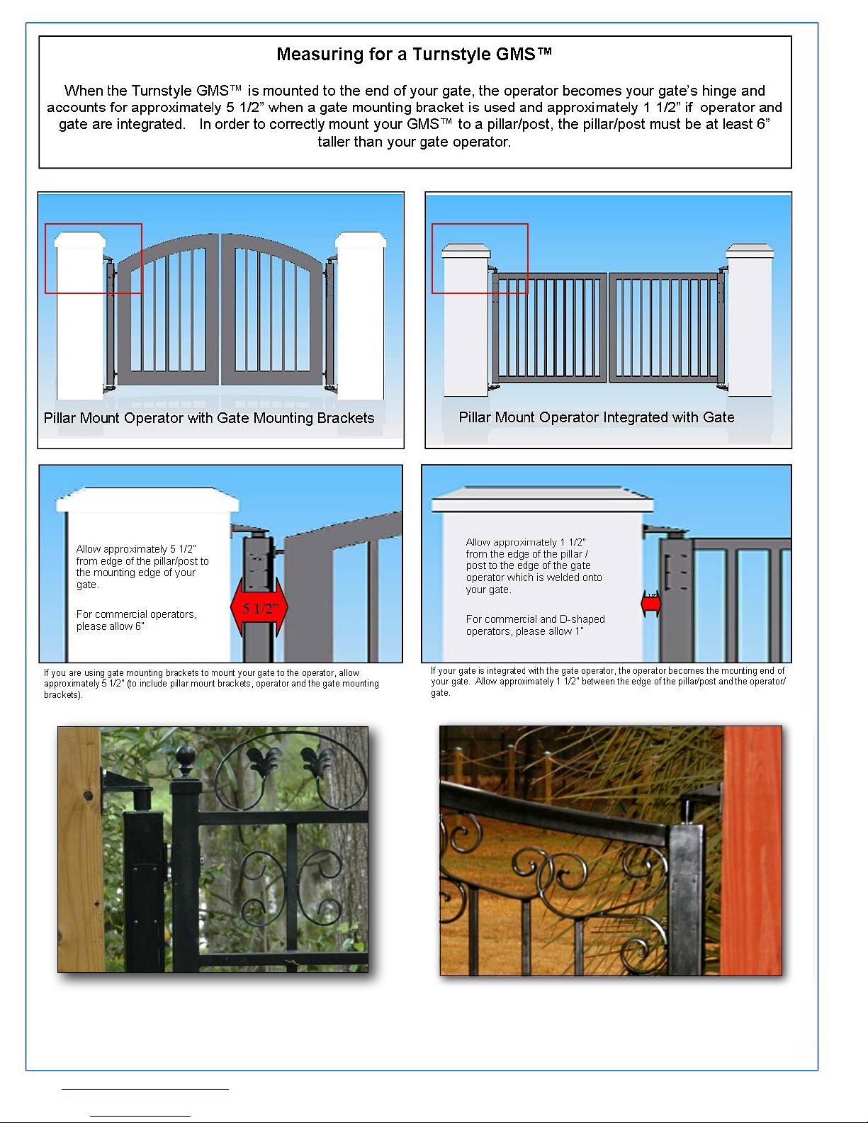
Turnstyle Pillar Mount GMS™:
(1) Turnstyle Pillar Mount operator; (2) for dual gate
For Automatic
GMS™
* (1) Control box with control board and two key chain
* (1) Rechargeable 12V 7AH Battery, (2) for dual gate
* (1) AC/AC Transformer
* (2) Safety Placards
Other items required:
Pre-Installation Considerations
!
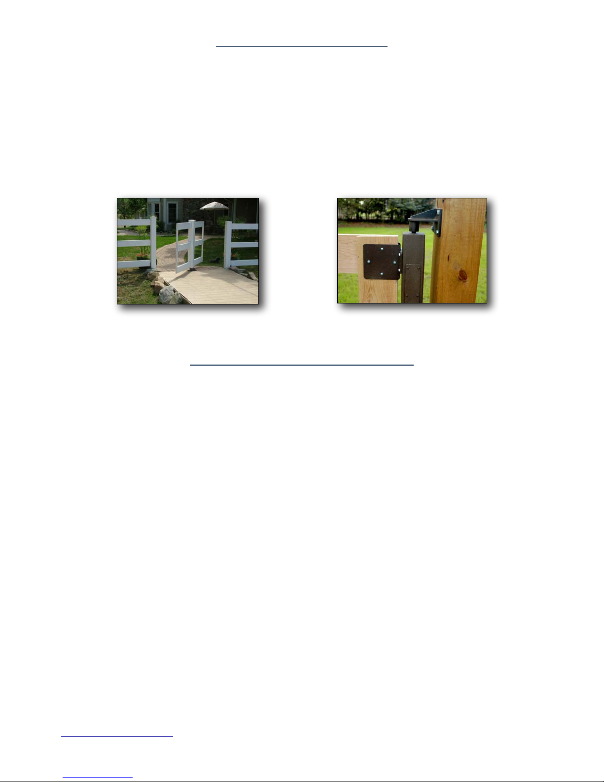
Turnstyle Gate Mounting Systems (GMS)™ are sold in two different mounting configurations, Pillar Mount and Ground
Mount. The Pillar Mount utilizes an owner provided post or pillar for its support and is attached to the pillar or post by means of
mounting brackets. The Ground Mount operates as a “stand alone” installation in which the Turnstyle operator is set in the
ground. Each system is available in both Manual and Automatic configurations.
" If your gate(s) are to be integrated (welded to a Turnstyle Operator,) you or your gate fabricator will need to take
special precautions. The inner tube containing the motor and other heat sensitive components must be removed prior
to and welding. Failure to take these precautions could result in heat damage to the motor and other internal parts of
your operator and render your warranty void. A separate instruction guide regarding welding and powder coating is
provided with operators intended for integration.
Ground Mount! Pillar Mount
Tools / Items required for installation:
Turnstyle Ground Mount GMS™:
Included with your package:
*
(1) Turnstyle Ground Mount operator; (2) for dual gate
installation
* (2) Ground Mount brackets; (4) for dual gate installation
* (2) Gate mounting brackets; (4) for dual gate installation
(if your gate is integrated with the Turnstyle operator,
you do not need gate mounting brackets
* Gate Mounting Hardware
* (1) Turnstyle Installation DVD
For Automatic
GMS™
* (1) Control box with control board and two key chain
remotes
* (1) Rechargeable 12V 7AH Battery, (2) for dual gate
installation
* (1) AC/AC Transformer
* (2) Safety Placards
Other items required:
* Shovel or Post Hole digger
* Tape measure
* Concrete mix
* Hex Bit Socket Set
* Level
* String level and string (for dual gate installations)
WWW.TURNSTYLEGATES.COM Foreign & Domestic Patents Issued & Pending! 1-800-548-2212 6
Turnstyle Pillar Mount GMS™
utilizing Gate Mounting Brackets
Integrated Turnstyle Pillar Mount
GMS
™
 Loading...