

Turnstiles FSW 900 User Manual
FSW 900
www.TURNSTILES.us / www.entrapass.com / 8641 S. Warhawk Road, Conifer, CO 80421 / 303-670-1099
Swing Gate Operator

www.TURNSTILES.us / www.entrapass.com / 8641 S. Warhawk Road, Conifer, CO 80421 / 303-670-1099
www.TURNSTILES.us / www.entrapass.com / 8641 S. Warhawk Road, Conifer, CO 80421 / 303-670-1099
CONTENTS
Important Safety Information
Important Safety Instructions ....................................... 4
Important Installation Instructions ................................ 4
General Safety Precautions.........................................5
UL325 Gate Operator Classication ............................ 6
Installing the Warning Signs ........................................6
Restrictions and Warnings ...........................................7
Precautions..................................................................7
Entrapment Protection ................................................. 8
Manual release ............................................................ 9
Preinstallation Guidelines ............................................ 9
Technical specication
Gate Operator Specications ....................................10
Gate Operator Installation
Gate Operator Location ........................................... 10
Concrete Pad Size & Location ................................. 11
Gate Operator Bolt Down ........................................ 11
Measure and Weld the Gate Arm ............................. 12
Connecting the Gate Arm ......................................... 12
Limit Switch Setup ................................................... 13
Gate Operator Direction .......................................... 13
Electrical Installation
Power Switch Location ............................................ 14
AC Power Guidelines ............................................... 14
AC Power Connection ............................................. 14
Battery Power Connection ....................................... 15
Accessory Power ..................................................... 15
Master/Slave Connection ........................................ 16
Accessory Connections
Overview ....................................................................... 19
Photocell Sensor Connections ..................................... 20
Edge Sensor Connections ............................................ 21
Standard Reverse Connections .................................... 22
Open, Close, Stop Connections ................................... 22
External Reset Connection ........................................... 22
Access Control Connection .......................................... 23
Fire Lock Connection .................................................... 23
Radio Receiver Connections ........................................ 24
MagLock & Solenoid Lock Connections ....................... 24
Warning Light Connections .......................................... 25
Solar Panel Connections .............................................. 25
Loop & Loop Detectors
Basic Loop Layout ........................................................ 26
Loop Installation Guidelines ......................................... 26
Plug-In Loop Detector Connections .............................. 27
External Loop Detector Connections ............................ 27
Troubleshooting Tips
Fault Light Count .......................................................... 28
Spare Parts
....................................................................................... 30
Limited warranty
....................................................................................... 32
Gate Operator Adjustments
Reverse Sensitivity Adjustment ............................... 17
Reverse Sensitivity Shutdown ................................. 17
Close Time Delay Adjustment .................................. 18
DIP Switch Settings ................................................. 18

www.TURNSTILES.us / www.entrapass.com / 8641 S. Warhawk Road, Conifer, CO 80421 / 303-670-1099
www.TURNSTILES.us / www.entrapass.com / 8641 S. Warhawk Road, Conifer, CO 80421 / 303-670-1099
IMPORTANT SAFETY INFORMATION
Important Safety Instructions
WARNING - TO REDUCE THE RISK OF SEVERE
INJURY OR DEATH:
• READ AND FOLLOW ALL INSTRUCTIONS.
• Never let children operate or play with the gate
controls. Keep remote controls away from children.
• Always keep people and objects away from the
gate. NO ONE SHOULD CROSS THE PATH OF A
MOVING GATE.
• Test the gate operator monthly. The gate MUST
reverse on contact with a rigid object or when an
object activates a non-contact sensor. If necessary,
adjust the force or the limit of travel and then retest
the gate operator. Failure to properly adjust and retest
the gate operator can increase the risk of injury or
death.
• Use the manual release mechanism only when the
gate is not moving.
• KEEP GATE PROPERLY MAINTAINED. Have
a qualied service person make repairs to gate
hardware.
• The entrance is for vehicles only. Pedestrians must
use a separate entrance.
• SAVE THESE INSTRUCTIONS.
Important Installation Instructions
1. Install the gate operator only when the following
conditions have been met:
• The operator is appropriate for the type and usage
class of the gate.
• All openings of a horizontal slide gate have been
guarded or screened from the bottom of the gate to
a minimum of 4 feet (1.25 m) above the ground to
prevent a 2.25 inch (55 mm) diameter sphere from
passing through openings anywhere in the gate or
through that portion of the adjacent fence that the gate
covers when in the open position.
• All exposed pinch points are eliminated or guarded.
• Guarding is supplied for exposed rollers.
2. The operator is intended for installation on gates used
by vehicles only. Pedestrians must be provided with a
separate access opening.
3. To reduce the risk of entrapment when opening and
closing, the gate must be installed in a location that
allows adequate clearance between the gate and
adjacent structures. Swinging gates shall not open
outward into public access areas.
4. Before installing the gate operator, ensure that the gate
has been properly installed and that it swings freely in
both directions. Do not over-tighten the operator clutch or
pressure relief valve to compensate for a damaged gate.
5. User controls must be installed at least 6 feet (1.83
m) away from any moving part of the gate and located
where the user is prevented from reaching over, under,
around or through the gate to operate the controls.
Controls located outdoors or those that are easily accessible shall have security features to prevent unauthorized
use.
6. The Stop and/or Reset buttons must be located within
line-of-sight of the gate. Activation of the reset control
shall not cause the operator to start.
7. All warning signs and placards must be installed
and easily seen within visible proximity of the gate. A
minimum of one warning sign shall be installed on each
side of the gate.

www.TURNSTILES.us / www.entrapass.com / 8641 S. Warhawk Road, Conifer, CO 80421 / 303-670-1099
www.TURNSTILES.us / www.entrapass.com / 8641 S. Warhawk Road, Conifer, CO 80421 / 303-670-1099
Important Installation Instructions (continued)
8. For gate operators that utilize a non-contact sensor
(photo beam or the like):
• See instructions on the placement of non-contact
sensors for each type of application.
• Exercise care to reduce the risk of nuisance tripping,
such as when a vehicle trips the sensor while the
gate is still moving.
• Locate one or more non-contact sensors where the
risk of entrapment or obstruction exists, such as at
the reachable perimeter of a moving gate or barrier.
• Use only FAAC “Photobeam” photoelectric eyes to
comply with UL325.
9. For gate operators that utilize a contact sensor (edge
sensor or similar):
• Locate one or more contact sensors where the risk
of entrapment or obstruction exists, such as at the
leading edge, trailing edge, and post mounted both
inside and outside of a vehicular horizontal slide
gate
• Locate one or more contact sensors at the bottom
edge of a vehicular vertical lift gate.
• Locate one or more contact sensors at the bottom
edge of a vertical barrier (arm).
• Locate one or more contact sensors at the pinch
point of a vehicular vertical pivot gate.
• Locate hard-wired contact sensors and wiring so
that communication between sensor and gate
operator is not subjected to mechanical damage.
• Locate wireless contact sensors, such as those
that transmit radio frequency (RF) signals, where
the transmission of signals are not obstructed or
impeded by building structures, natural landscaping
or similar hindrances. Wireless contact sensors shall
function under their intended end-use conditions.
• Use only FAAC XS 55 edge sensors with with CN 60
E controller.
General Safety Precautions
Gate Construction
Vehicular gates should be constructed and installed
in accordance with ASTM F2200: Standard Specication for Automated Vehicular Gate Construction.
For more information, contact ASTM at: www.astm.org
Installation
• If you have any questions or concerns regarding the
safety of the gate operating system, do not install the
operator and consult the manufacturer.
• The condition of the gate structure itself directly
aects the reliability and safety of the gate operator.
• Only qualied personnel should install this equipment.
Failure to meet this requirement could cause severe
injury and/or death, for which the manufacturer
cannot be held responsible.
• The installer must provide a main power switch that
meets all applicable safety regulations.
• It is extremely unsafe to compensate for a damaged
gate by increasing hydraulic pressure.
• Install devices such as reversing edges and photo
beams to provide better protection for personal
property and pedestrians. Install reversing devices
that are appropriate to the gate design and
application.
• Before applying electrical power, ensure that voltage
requirements of the equipment correspond to the
supply voltage. Refer to the label on your gate
operator system.
Usage
• Use this equipment only in the capacity for which it
was designed. Any use other than that stated should
be considered improper and therefore dangerous.
• The manufacturer cannot be held responsible
for damage caused by improper, erroneous or
unreasonable use.
• If a gate system component malfunctions, disconnect
the main power before attempting to repair it.
• Do not impede the movement of the gate, you may
injure yourself or damage the gate system as a result.
• This equipment may reach high thermal temperatures
during normal operation, therefore use caution when
touching the external housing of the gate operator.
• Use the manual release mechanism according to the
procedures presented in this manual.
• Before performing any cleaning or maintenance
operations, disconnect power to the equipment.
• All cleaning, maintenance or repair work must
performed by qualied personnel.

www.TURNSTILES.us / www.entrapass.com / 8641 S. Warhawk Road, Conifer, CO 80421 / 303-670-1099
www.TURNSTILES.us / www.entrapass.com / 8641 S. Warhawk Road, Conifer, CO 80421 / 303-670-1099
UL325 Gate Operator Classications
RESIDENTIAL VEHICULAR GATE OPERATOR CLASS I
A vehicular gate operator system intended for use in a single family dwelling, garage or associated parking area.
COMMERCIAL / GENERAL ACCESS VEHICULAR GATE OPERATOR CLASS II
A vehicular gate operator system intended for use in commercial locations or buildings such as multi-family housing
units (ve or more single family units), hotels, parking garages, retail stores or other buildings that service the general
public.
INDUSTRIAL / LIMITED ACCESS VEHICULAR GATE OPERATOR CLASS III
A vehicular gate operator system intended for use in industrial locations or buildings such as factories, loading docks
or other locations not intended to service the general public.
RESTRICTED ACCESS VEHICULAR GATE OPERATOR CLASS IV
A vehicular gate operator system intended for use in guarded industrial locations or buildings such as airport security
areas or other restricted access locations that do not service the general public, and in which unauthorized access is
prevented via supervision by security personnel.
Installing the Warning Signs
This FAAC gate operator is supplied with two
warning signs to alert people that a possible
hazard exists and that appropriate actions
should be taken to avoid the hazard or to
reduce exposure to it.
Permanently install one warning sign on each
side of the gate so they are fully visible to
trac and pedestrians.
Use appropriate hardware such as metal
screws (not supplied) to permanently install
each warning sign.
www.TURNSTILES.us / www.entrapass.com / 8641 S. Warhawk Road, Conifer, CO 80421 / 303-670-1099
www.TURNSTILES.us / www.entrapass.com / 8641 S. Warhawk Road, Conifer, CO 80421 / 303-670-1099
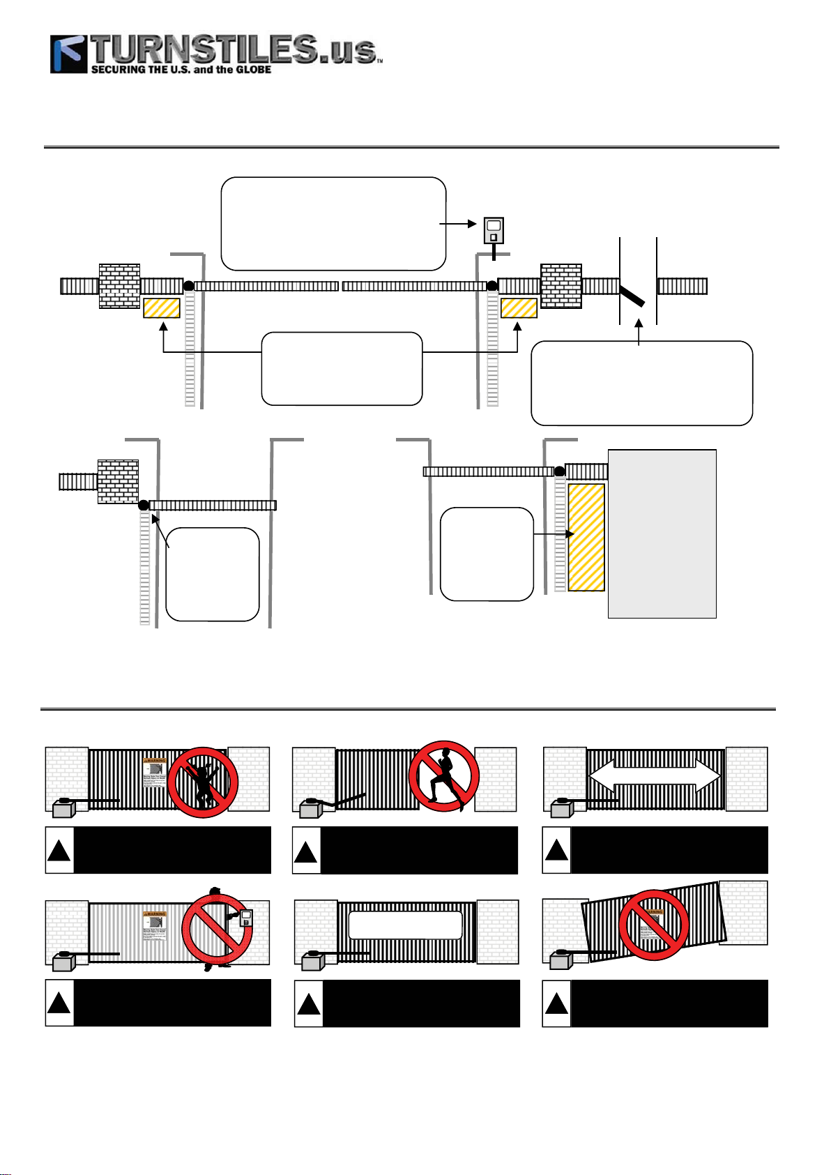
Restrictions and Warnings
Gate operator controls must be placed far
enough from the gate to prevent the user
from coming in contact with the gate while
operating the controls. All activating devices
must be installed in a clear line-of-sight with
Fence
Pilaster
the gate and its travel. Be sure to mount all
devices clearly out of reach of through gate.
Vehicular Gate Only
Pilaster
Fence
Access
Pedestrian
Fence
Pilas-
Fence
Precautions
Vehicular Gate Only
Mount hinges on
the corner of
pilasters to help
prevent
entrapment
areas.
Provide spacing between the
hinge, gate and pilaster to
reduce the risk of entrapment for
this area.
Provide spacing
between the
hinge, gate and
building to
reduce the risk of
entrapment in
this area
The operator is intended for installation only
on swing gates used for vehicular traffic.
Pedestrians must be provided with a sepa-
rate access opening.
NO ONE SHOULD CROSS THE PATH OF
A MOVING GATE!
Building
Or
Structure
Or
Fence
DO NOT allow children to play
near, on or with the gate, gate
!
operator, or any of its controls.
DO NOT allow pedestrian use of the
vehicular gate. No one should cross
!
the path of a moving gate!
1000 lb. Maximum
DO NOT mount operating devices
accessible through the gate or in
!
between the gate and wall.
DO NOT mount the gate operator
to a gate heavier than 1000 lbs.
!
Maximum gate weight = 1000 lbs.
40 Feet Maximum
DO NOT mount the gate operator
to a gate longer than 40 feet.
!
Maximum gate length = 40 feet.
DO NOT mount the gate operator
on uphill or downhill applications.
!
Do not allow gate to free swing.

www.TURNSTILES.us / www.entrapass.com / 8641 S. Warhawk Road, Conifer, CO 80421 / 303-670-1099
www.TURNSTILES.us / www.entrapass.com / 8641 S. Warhawk Road, Conifer, CO 80421 / 303-670-1099
Entrapment Protection
Internal Entrapment Prevention:
This vehicular gate operator is equipped with an inherent (Type A) entrapment sensing device. The system will sense an obstruction
in both the open and close cycles, and will reverse the direction of the gate travel upon encountering an obstruction. If the system
detects a second obstruction before reaching the full open or close limit after the initial reversal, a warning alarm will activate and
the operator will require a reset before resuming normal operation. This is called a “Hard Shutdown”. Please read and follow the
“Shutdown Conditions” section of this manual for more directions.
External Entrapment Prevention:
Non-contact and/or contact sensors must be installed to provide external entrapment prevention in accordance with UL325 section
3.1. Use only UL325 compliant devices and low voltage (24V) devices. Carefully follow the installation manual for the UL325 device
used for installation, usage, and maintenance.
Non-Contact Sensors (Photo Beams):
Non-contact sensors generally are photoelectric cells or like devices. For gate operators utilizing non-contact sensors:
Refer to the diagram below for placement of non-contact sensors.
Use care to reduce the risk of nuisance tripping, such as when a vehicle trips the sensor while the gate is still moving.
One or more non-contact sensors shall be located where a risk of entrapment or obstruction exists, such as the perimeter reachable
by a moving gate or barrier. Use caution when installing non-contact sensors since some devices only cover a select area. For
example, a photo beam will not cover the full height of a gate/fence area. Refer to the diagram below.
Contact Sensors (Edge Sensors):
Contact sensors generally are sensing edges or like devices. For gate operators utilizing contact sensors:
Refer to the diagram below for placement of contact sensors.
One or more contact sensors shall be located where the risk of entrapment or obstruction exists, such the leading edge, trailing edge,
and posts mounted inside and outside of the vehicular slide gate and motor.
Hardwired contact sensors shall be located and its wiring arranged so the communication between the sensor and the gate operator
is not subject to any mechanical damage.
Wireless contact sensors such as ones that transmit radio frequency (RF) signals to the gate operator for entrapment prevention
functions shall be located where the transmission of the signals are not obstructed or impeded by building structures, landscaping
or similar obstructions. All wireless contact sensors shall function under the intended end-use conditions.
Bottom Edge
Sensor If Greater
Than 6 Inches
Standard Reverse beams help
prevent the gate from hitting ob-
structions during the close cycle.
CAUTION: This beam only detects
at the installed height.
One or more Edge Sensors shall
be located on the bottom edge of
the gate if the gate travels more
than 6” above ground at any point
of its arc or travel.
One or more Edge Sensors could
be located on the inside and
outside leading edge of the gate.
Wall or Fence
Open beams help protect
areas between the gate and
an adjacent fence or wall.
CAUTION: This beam only
detects at the installed height.
www.TURNSTILES.us / www.entrapass.com / 8641 S. Warhawk Road, Conifer, CO 80421 / 303-670-1099
www.TURNSTILES.us / www.entrapass.com / 8641 S. Warhawk Road, Conifer, CO 80421 / 303-670-1099
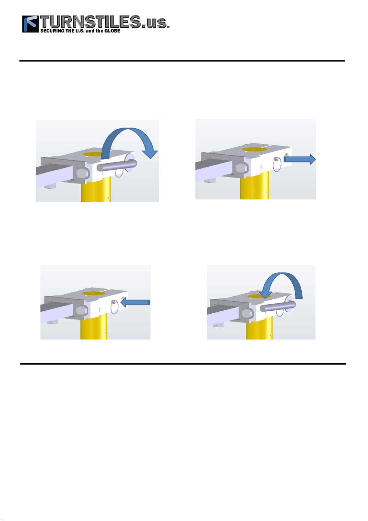
Manual Release
To manually release the gate operator:
TURN POWER OFF. Use the emergency release/shut o only when the gate is not moving. Make sure power for the gate operator is OFF by using the On/O switch located inside the cover on the left side of the controller.
• Remove the top arm cap cover.
• Lift the Release Handle.
• Remove the Alignment Pin.
• Move the gate to the desired location.
To reengage the gate operator:
Make sure power is OFF.
• Manually move the gate to align the arm with the output shaft and insert the Alignment Pin.
• Press the Release Handle down until tight. The release handle should be tightened so the arm connector does not slip on the
output shaft during gate operation.
• Attach the top arm cap cover.
• Turn power on. Make sure the gate and all reversing devices are operating correctly.
Preinstallation Guidelines
Before starting any installation, consider the following guidelines:
• Install the gate system and gate in accordance with ASTM F220-02 Standard Specication for Automated Vehicular Gate Construction
• Install the gate system and gate in accordance with UL325 standards.
• Provide spacing between the gate and any structure such as a building, wall or fence to reduce the risk of entrapment in this area.
• Install over-travel stops at both ends of the gate rail or track to help prevent the gate from derailing
• Be sure the gate is properly installed and moves freely. Repair or replace worn or damaged gate hardware before installing the
gate operator.
• Add safety devices such as warning signs, photo eyes, and reverse edges to help prevent injuries or death.
• Reduce all pinch points and protect all entrapment areas.
• If pedestrian trac will be present, provide a separate pedestrian walk gate clear from the path of the automatic gate.
• Loops and loop detectors are required to help prevent the gate from closing on vehicles. Loops do not protect pedestrian trac.
• Select the proper gate operator for the installation. Consider the usage, capacity, gate size, gate weight, and needed features an
safety accessories.
Model FSW 900 Swing Gate Operator
www.TURNSTILES.us / www.entrapass.com / 8641 S. Warhawk Road, Conifer, CO 80421 / 303-670-1099
The FAAC Model FSW 900 is an electro-mechanical vehicular swing gate operator. The direct drive 24V motor allows for smooth
start and stop operation, with easy to set limit switches. It has a built in battery backup system and 2 accessory power plugs. The
standard articulated arm allows for an easy installation.
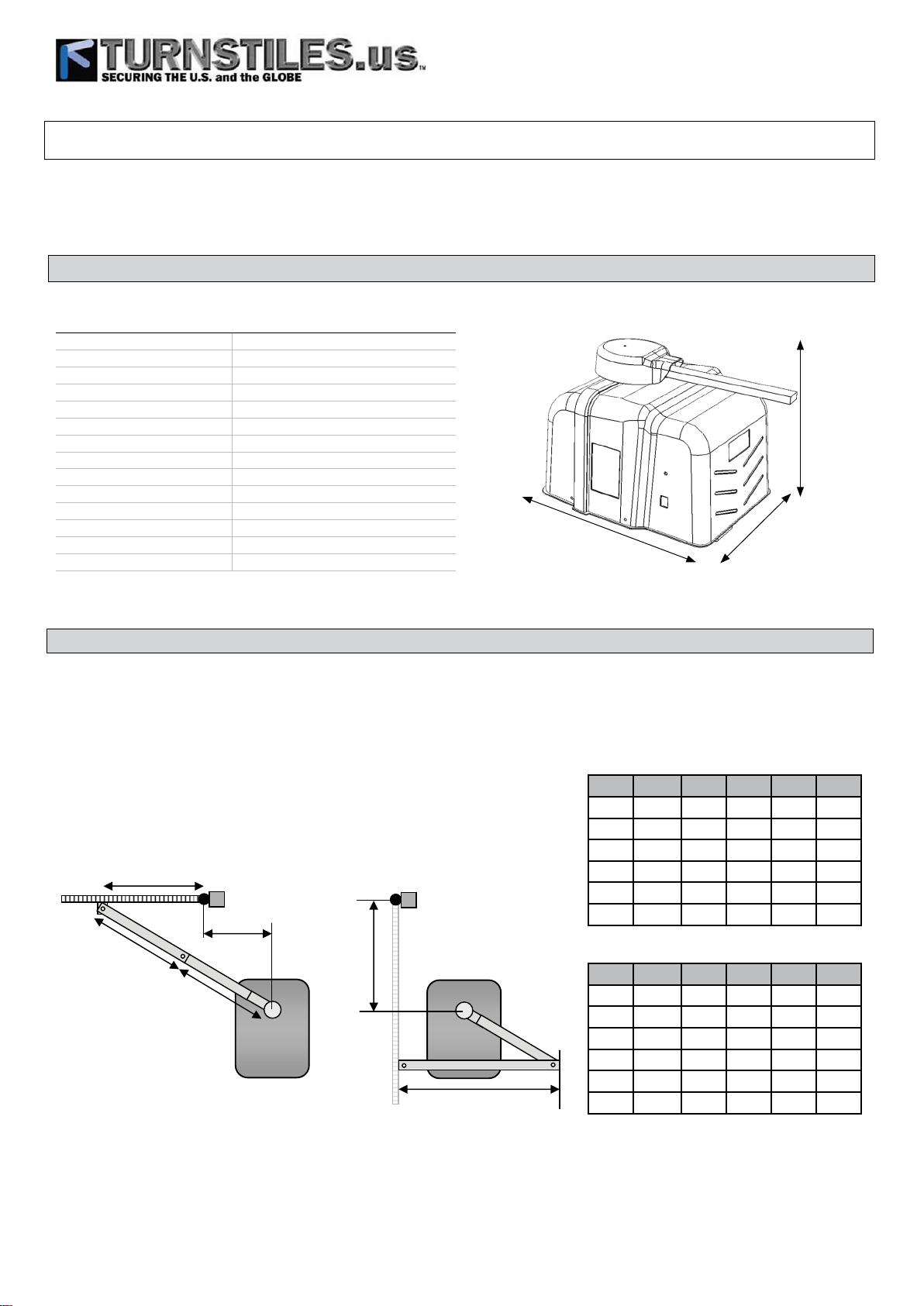
TECHNICAL SPECIFICATION
Gate Operator Specications
Input voltage 120 VAC (+5% -5%)
Power 500 W
Current 5 A
Motor voltage 24 VDC
Motor power 0.67 hp (0.5 KW)
Leaf max weight 800 lb (363 Kg)
Leaf max length 18 ft (5.5 m)
AC accessory outlets 2 GFCI protected
AC accessory current 4 A
Gate speed 90° in approx 14 sec.
Gearbox 900:1 fail secure
Use frequency 75 cycles/h
Operating temperature -4°F ÷ 131°F (-20°C ÷ +55°C)
Operator weight 125 lb (57 Kg)
23.5 in
18.5 in
18 in
GATE OPERATOR INSTALLATION
Gate operator location:
Use the following steps to locate the standard position of the gate operator. The charts may be used for alternate locations.
1. D = 35" from hinge center straight back.
2. E = 11" from D to Operator Output Shaft.
3. DISTANCE = 45" from gate to wall.
A
E
B
Long Arm
C
Short Arm
D
Distance
A B C D E Dist
46 35.5 29.5 35 11 45
46.75 35.5 33.5 42 11 37
46.75 37 31.5 40 11 41
47.25 37.25 30 37 11 45
47 35 29.5 32 11 45
42.5 33 26.5 28.5 11 41
Dimensions in inches
A B C D E Dist
34.5 34.75 29.5 35 14 43
44 36.5 32.5 42 14 32
44 37 30.5 40 14 40
45 37 30.5 37 14 43
44.75 35.75 29.5 32 14 44
41 39 27.5 28.5 14 41
Dimensions in inches
 Loading...