

Turnstiles ETV Series Installation And Operation Manual

www.TURNSTILES.us * 8641 South Warhawk Road * Conifer, CO 80433
www.TURNSTILES.us
ETV Series Installation Guide
Version 2.0
Version 2.0
by
Ted T Case
Rights Reserved © 2006
www.TURNSTILES.us * 8641 South Warhawk Road * Conifer, CO 80433
DVR Installation and Operation
Warnings and Disclaimers Top 10 List
Attention all DVR Users and Installers: IMPORTANT—READ
CAREFULLY!
When the DVR starts up, you are automatically logged on as a user with Administrator rights. This
enables you to configure all necessary networking and connection protocols and configure the DVR
setup without restrictions.
Please review the following list of do’s and don’ts for successful installation and operation of the
DVR.
Failure to comply with any of the recommendations on the list will VOID YOUR
WARRANTY.
WARNINGS AND DISCLAIMERS TOP 10 LIST
1. DO protect the DVR by using an EL-USA approved hardware Firewall
If connecting the DVR to the Internet or ANY internal network with remote access, you MUST use an EL-USA approved
hardware Firewall to protect the DVR. Failure to protect the DVR from network-based attacks will void the warranties, expressed
or implied. WHILE EL-USA TAKES VERY SERIOUSLY THE THREAT OF VIRUS ATTACKS AND THE DAMAGE
THEY CAUSE, EL-USA ACCEPTS NO RESPONSIBILITY FOR LOSS OF DATA OR DAMAGES DUE TO VIRUSES,
DATA ATTACKS, SOFTWARE UPDATES, OR THE INABILITY TO USE THE PRODUCT. ANY LOSSES
COVERED ARE LIMITED IN VALUE NOT TO EXCEED THE ORIGINAL PURCHASE PRICE OF THE PRODUCT.
2. DO place the DVR in an environmentally safe location
Please keep the following criteria in mind when determining an environmentally safe location for the DVR.
• Room temperature range should be between 50o F and 90o F
• Humidity should stay between 10% and 65% nominally
• Environment should not be excessively dusty or exposed to airborne particulates.
3. DO protect the DVR power source
An uninterruptible power supply (UPS) and a power conditioner are strongly recommended for use with EL-USA DVR products.
4. DO monitor the condition of the DVR periodically
All computer-based products may experience difficulties occasionally so monitor the condition of the DVR and report any issues
to EL-USA or the EL-USA Dealer.
5. DO follow recommended updates and maintenance procedures
EL-USA provides periodic recommended hardware/software updates and system maintenance procedures to ensure the DVR
system is optimized to run efficiently and meet the demands of your evolving business needs.
6. DO NOT install any other software or Hardware on the DVR
This includes the installation of ANY software/hardware not provided by EL-USA, except if the software/hardware is specifically
recommended and you are instructed to perform the installation by an authorized EL-USA Support Technician.
7. DO NOT customize the operating system
This includes adding screensavers, adjusting power save settings, changing the desktop, fonts or any other aspect.
8. DO NOT use the DVR for any purpose other than the intended use
This includes browsing the Internet, playing music or CD’s, playing games, or using the DVR for any purpose other than the
intended use by the manufacturer.
9. DO NOT unplug the mouse or keyboard while the system is on
Plugging or unplugging the mouse and/or keyboard while the system is on could damage the port rendering the mouse and/or
keyboard permanently inoperable.
10. DO NOT change operating system user names and passwords
The operating system user names and passwords cannot be changed and the DVR cannot be added to a domain because either
action will reduce functionality and potentially render the DVR inoperable.

ETV Series Installation Guide
www.TURNSTILES.us * 8641 South Warhawk Road * Conifer, CO 80433
Index
• Package Contents .........................................................................................3
• Rear Panel Connections ...............................................................................4
o ETV-30-04 ............................................................................................4
o ETV-30-16 ............................................................................................5
o ETV-60/120-16 .....................................................................................6
o ETV-240-16 ..........................................................................................7
o ETV-120/240-32 ...................................................................................8
• Basic Connections........................................................................................9
o Keyboard.............................................................................................9
o Mouse ..................................................................................................9
o VGA Monitor Port................................................................................9
o BNC Camera Connectors...................................................................9
o RCA Audio Connectors....................................................................10
o Speaker Output.................................................................................10
o AC Power cable.................................................................................10
o AC Power Connector........................................................................10
o Power Switch ....................................................................................10
• Optional and Advanced Connections........................................................11
o Printer Port........................................................................................11
o Com Port / RS-232 ............................................................................11
o USB Ports..........................................................................................11
o Network Connector...........................................................................11
o Sensor/Relay Modules......................................................................12
DIO-0804 .................................................................................12
• Getting the DVR on a Network....................................................................15
o Connections......................................................................................15
o The ipconfig command.....................................................................17
o Accessing the Router.......................................................................19
o Port Forwarding the Router .............................................................20
Sample D-Link Router............................................................21
Sample Linksys Router .........................................................22
o Windows TCP/IP ...............................................................................25
o Network Troubleshooting ................................................................27
• Elite Technology DVR Ports.......................................................................31

ETV Series Installation Guide
www.TURNSTILES.us * 8641 South Warhawk Road * Conifer, CO 80433
Index (cont.)
• POS Connections........................................................................................32
o Assemble the cables ........................................................................32
o Wiring the Adapters..........................................................................33
o USB Adapter......................................................................................34
o Pole Display Adapter........................................................................34
o Using HyperTerminal........................................................................35
o Data Capture with HyperTerminal ...................................................37
o Data Capture with POS Collector ....................................................39
o Common Baud Rates and Settings.................................................40
o POS Troubleshooting Tips...............................................................41
• POS Connection Wiring Diagrams.............................................................42
o The DB-9 to RJ-45 Adapter ..............................................................42
o Gilbarco PC.......................................................................................43
o Liquor POS........................................................................................44
o Micros 8700 IDN................................................................................45
o Retail Pro...........................................................................................46
o TVS Interface.....................................................................................49
o Generic PC Based Data Tap.............................................................50
• Contact Information ....................................................................................51
2
Package Contents
www.TURNSTILES.us * 8641 South Warhawk Road * Conifer, CO 80433
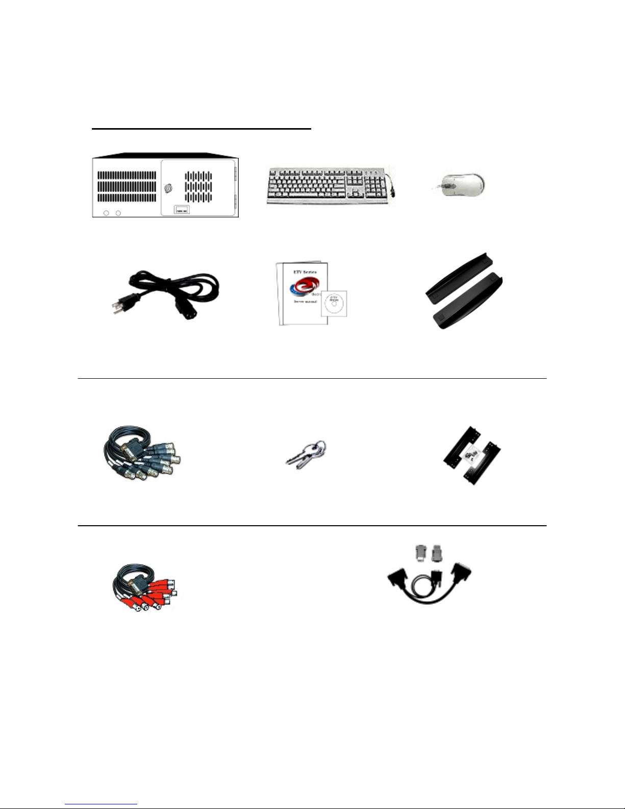
ETV 30-04 Package Includes
DVR Keyboard Mouse
(Appearance may vary)
AC Power Cable Manuals and Support Cds Support Brackets (Feet)
Any 16 channel DVR will also include:
1- BNC Camera Rack door Keys Rack mount Brackets
connector assembly
Optional Accessories
1-RCA Audio POS Y-connector Kit
connector assembly
3
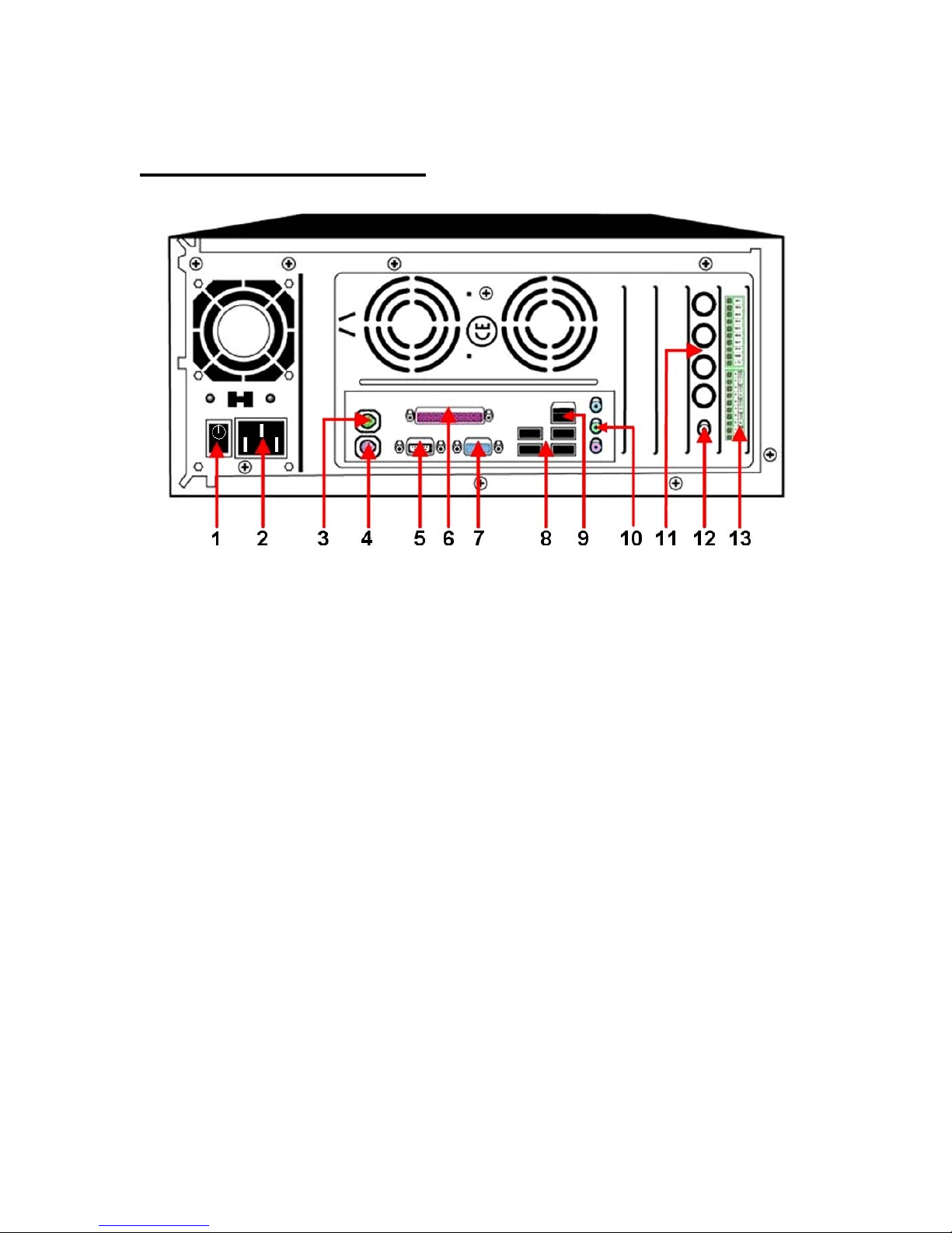
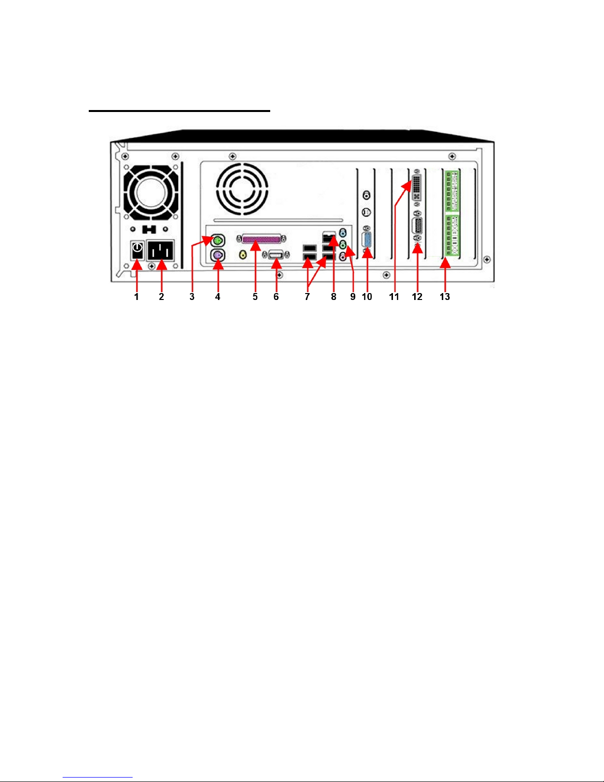
ETV-30-04
www.TURNSTILES.us * 8641 South Warhawk Road * Conifer, CO 80433
Rear Panel Connections
1. Power Switch
2. AC Power Connector
3. Mouse Connector (Green)
4. Keyboard Connector (Purple)
5. Com Port (RS-232)
Use for PTZ camera control or POS data input
6. Printer
7. VGA Monitor
8. USB Connectors
Use for extra POS connections, USB printer, or USB Hard drives
9. Network (LAN/Internet) Connector
RJ-45 connector for Cat-5 twisted pair cable
10. Speaker Output (Green)
Requires 1/8” stereo phone plug
11. BNC Camera Input Connectors
Camera 1 is top connector
12. NTSC Output (Spot Monitor)
Standard RCA Connector (White)
13. Sensor/Relay Module
(Optional Component DIO-0804)
4
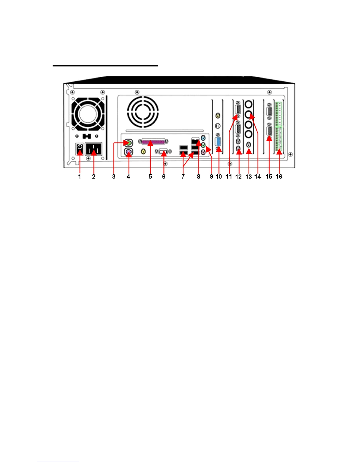
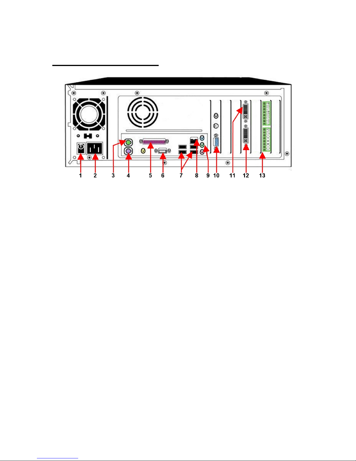
ETV-30-16
www.TURNSTILES.us * 8641 South Warhawk Road * Conifer, CO 80433
Rear panel connections
1. Power Switch
2. AC Power Connector
3. Mouse Connector (Green)
4. Keyboard Connector (Purple)
5. Printer
6. Com Port (RS-232)
Use for PTZ camera control or POS data input
7. USB Connectors
Use for extra POS connections, USB printer, or USB Hard drives
8. Network (LAN/Internet) Connector
RJ-45 connector for Cat-5 twisted pair cable
9. Speaker Output (Green)
Playback recorded data only. (Requires 1/8” stereo phone plug)
10. VGA Monitor
11. 16 Channel Audio Input
(Optional Component) Attach two DB-15/RCA flying lead connectors
12. Live Audio Output
Monitor live audio only. (Standard RCA connector - black)
13. NTSC Output (Spot Monitor)
Standard RCA Connector (White)
14. BNC connectors NOT USED
These connectors are NOT USED on a 16 channel DVR
15. 16 Channel Video Input
Attach two DB-15/BNC flying lead connectors
16. Sensor/Relay Module
(Optional Component DIO-0804)
5
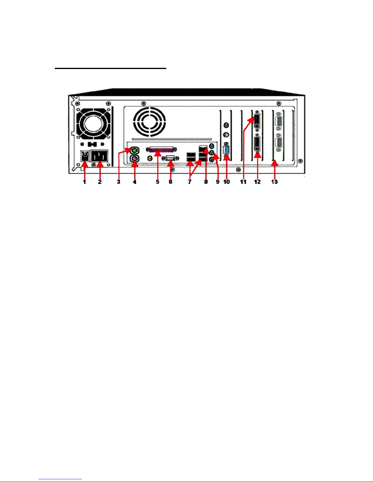
ETV-60-16 / ETV-120-16
www.TURNSTILES.us * 8641 South Warhawk Road * Conifer, CO 80433
Rear Panel Connections
1. Power Switch
2. AC Power Connector
3. Mouse Connector (Green)
4. Keyboard Connector (Purple)
5. Printer
6. Com Port (RS-232)
Use for PTZ camera control or POS data input
7. USB Connectors
Use for extra POS connections, USB printer, or USB Hard drives
8. Network (LAN/Internet) Connector
RJ-45 connector for Cat-5 twisted pair cable
9. PC Microphone Input (Pink) Speaker Output (Green)
Playback recorded data or 2-Way live audio chat.
(Requires 1/8” stereo phone plugs)
10. VGA Monitor
11. 16 Channel Video Input / 2 Channel Output
Attach DVI/BNC flying lead connector
12. ETV-60-16 = 4 Channel Audio Input / 2 Channel Output
ETV-120-16 = 8 Channel Audio Input / 2 Channel Output
Attach DB-15/RCA flying lead connector
13. Sensor/Relay Module
(Optional Component DIO-0804)
6
ETV-240-16
www.TURNSTILES.us * 8641 South Warhawk Road * Conifer, CO 80433
Rear panel Connections
1. Power Switch
2. AC Power Connector
3. Mouse Connector (Green)
4. Keyboard Connector (Purple)
5. Printer
6. Com Port (RS-232)
Use for PTZ camera control or POS data input
7. USB Connectors
Use for extra POS connections, USB printer, or USB Hard drives
8. Network (LAN/Internet) Connector
RJ-45 connector for Cat-5 twisted pair cable
9. PC Microphone Input (Pink) Speaker Output (Green)
Playback recorded data or 2-Way live audio chat.
(Requires 1/8” stereo phone plugs)
10. VGA Monitor
11. 16 Channel Video Input / 2 Channel Output
Attach the DVI / BNC flying lead connectors
12. 16 Channel Audio Input / 2 Channel Output
Attach the DVI / RCA flying lead connectors
13. Sensor/Relay Module
(Optional Component DIO-0804)
7
ETV-120-32 / ETV-240-32
www.TURNSTILES.us * 8641 South Warhawk Road * Conifer, CO 80433
Rear panel Connections
1. Power Switch
2. AC Power Connector
3. Mouse Connector (Green)
4. Keyboard Connector (Purple)
5. Printer
6. Com Port (RS-232)
Use for PTZ camera control or POS data input
7. USB Connectors
Use for extra POS connections, USB printer, or USB Hard drives
8. Network (LAN/Internet) Connector
RJ-45 connector for Cat-5 twisted pair cable
9. PC Microphone Input (Pink) Speaker Output (Green)
Playback recorded data or 2-Way live audio chat.
(Requires 1/8” stereo phone plugs)
10. VGA Monitor
11. 16 Channel Video Input / 2 Channel Output
Attach the DVI / BNC flying lead connectors
12. 16 Channel Audio Input / 2 Channel Output
Attach the DVI / RCA flying lead connectors
13. Channel 17 ~ 32 video Connectors (Black)
Attach DB-15/BNC flying lead connectors.
Top connector is for Video channels 17~24
Bottom connector is for video channels 25~32
(Video connectors for channels 17~32 may be in different location
depending on other installed options.)
8
Basic Connections
www.TURNSTILES.us * 8641 South Warhawk Road * Conifer, CO 80433
Connecting the hardware in the proper sequence and in the correct ports
will save you time and trouble during the installation of the DVR. The basic
connections should be made in the following order.
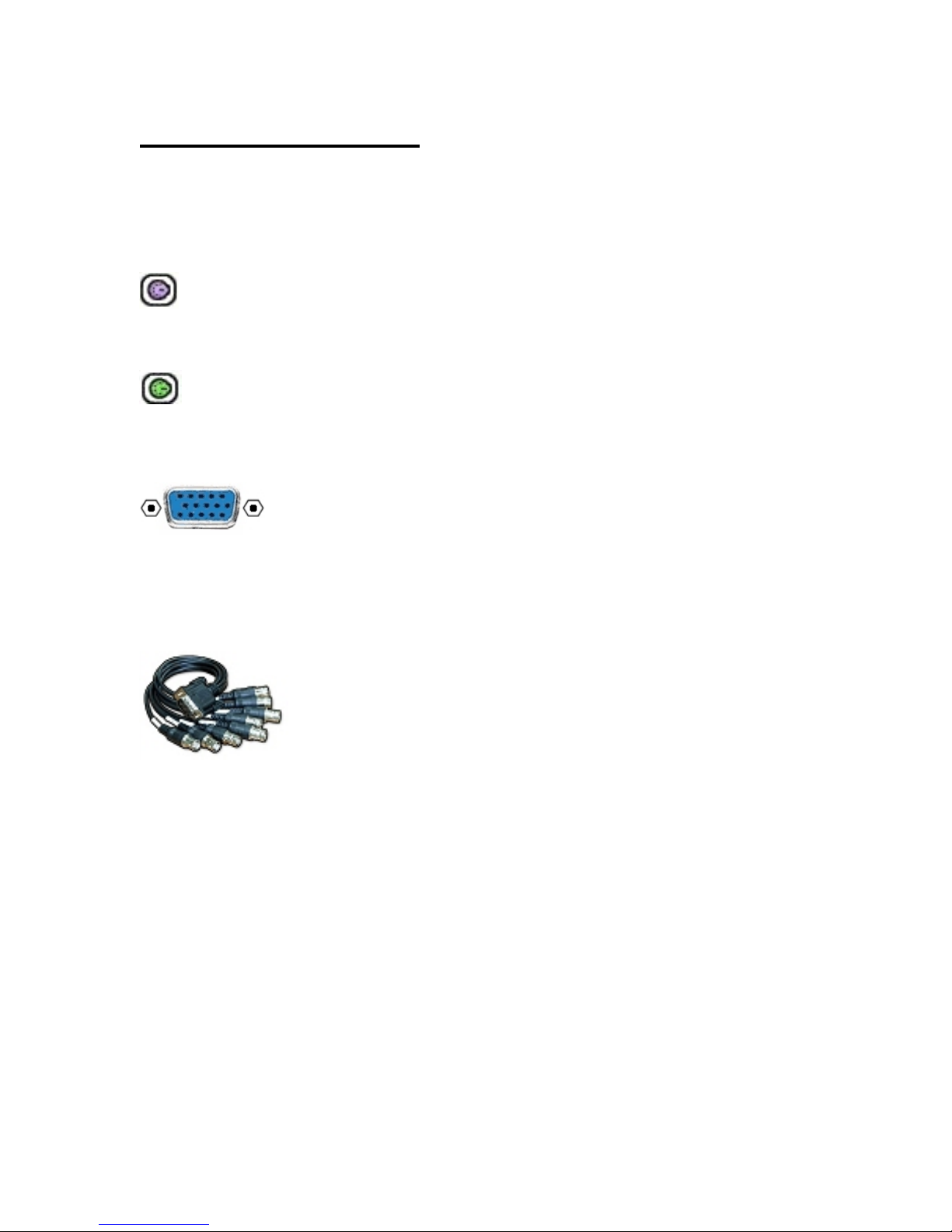
(Keyboard Port )
Keyboard – The keyboard connector is keyed (directional) and color
coded (purple) and should be connected first.
(Mouse Port )
Mouse – The mouse connector is also keyed and color coded (green) and
should be connect next.
(ETV-30-04 Video Port )
VGA Monitor Port – The video monitor connector is directional (D-
shaped shell) and color coded (blue) It may be found in different locations
on various models. Consult the Rear Panel Connections guide for your
model to determine the location.
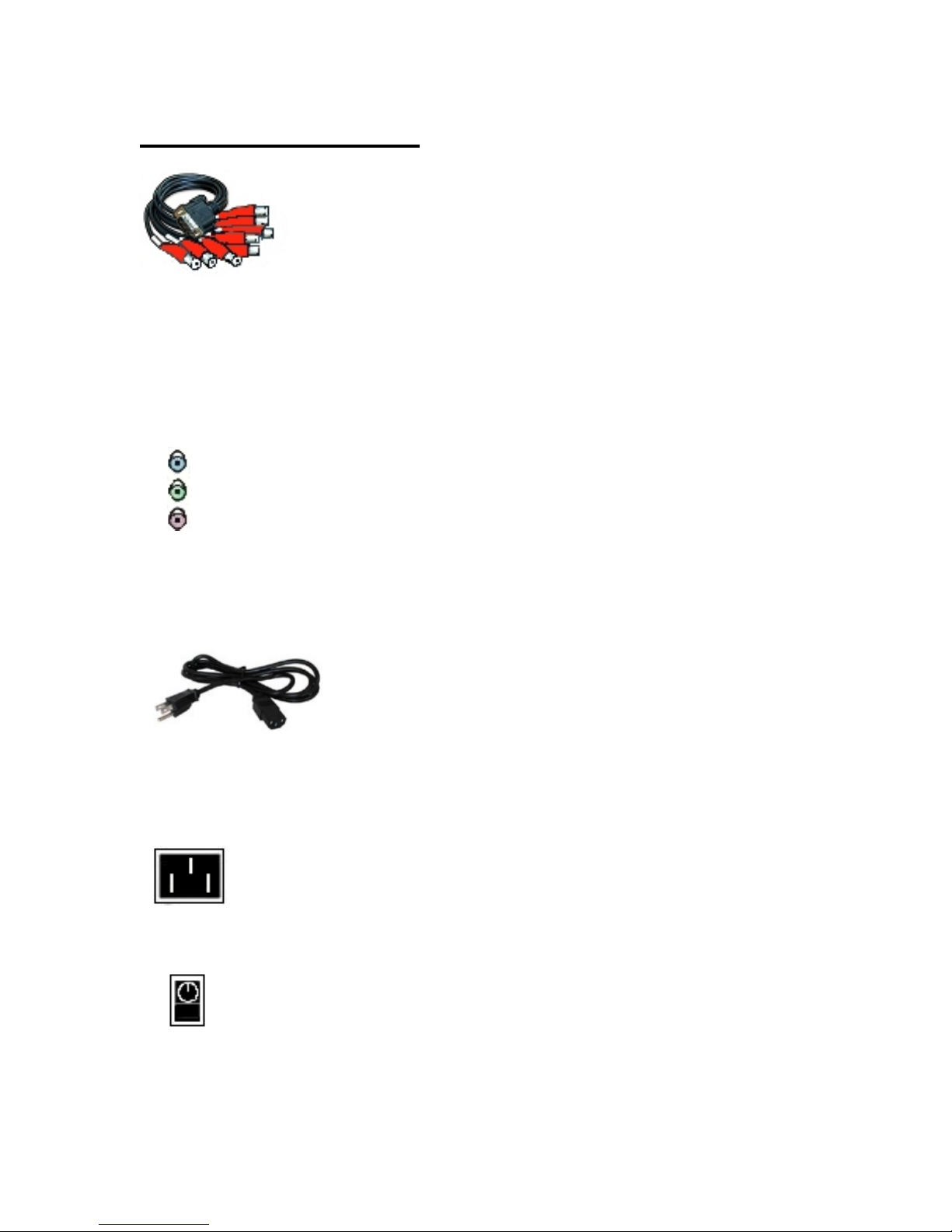
(BNC Camera connectors )
BNC Camera connectors – The ETV 30-16 will include 2 DB-15 to flying
BNC leads. (8 input leads on each)
The ETV-60-16, 120-16, and 240-16 will have 1 DVI to flying BNC leads (16
input leads + 2 spot monitor outputs. #17 and #18 are monitor outputs)
Consult the Rear Panel Connections guide for your model for location of
these connections.
Try to have all of your cameras attached and powered up before turning on
the DVR. If not, the DVR may sense no input signal and turn off the inputs.
If that happens, make sure your cameras are attached and powered, and
then restart the DVR. Then open ‘Settings’ and assign a frame rate to the
affected channels to reactivate them.
9
Basic Connections
www.TURNSTILES.us * 8641 South Warhawk Road * Conifer, CO 80433
(RCA Audio Connectors )
RCA Audio Connectors- (Optional) Consult your specific model on
the ‘Rear Panel connections’ section as these components vary.
The ETV-240-16 will have 1 DVI to flying RCA leads (16 inputs + 2 outputs.
#17 is line level, #18 is speaker level. These outputs are for monitoring
‘Live’ recording only. Playback of recorded data is heard through the PC
Speaker Output.)
(Microphone/Speaker Input/Output )
PC Microphone Input (Pink)/ Speaker Output (Green)- These
connectors are for playback of recorded data or 2 - Way Live Audio Chat
function. Live audio monitoring is routed through the RCA audio connector
assemblies.
(AC Power cable )
AC Power Cable – The final step in basic setup is to attach the AC power
cable to the AC power connector. The DVR may automatically start up
when you make this connection.
(AC Power Connector )
AC Power connector – Attach AC Power Cable from Line Conditioner.
(Power Switch )
Power Switch –
the power switch off and then back on.
If the DVR does not power up when you plug it in, toggle
10
Optional and Advanced Connections
www.TURNSTILES.us * 8641 South Warhawk Road * Conifer, CO 80433
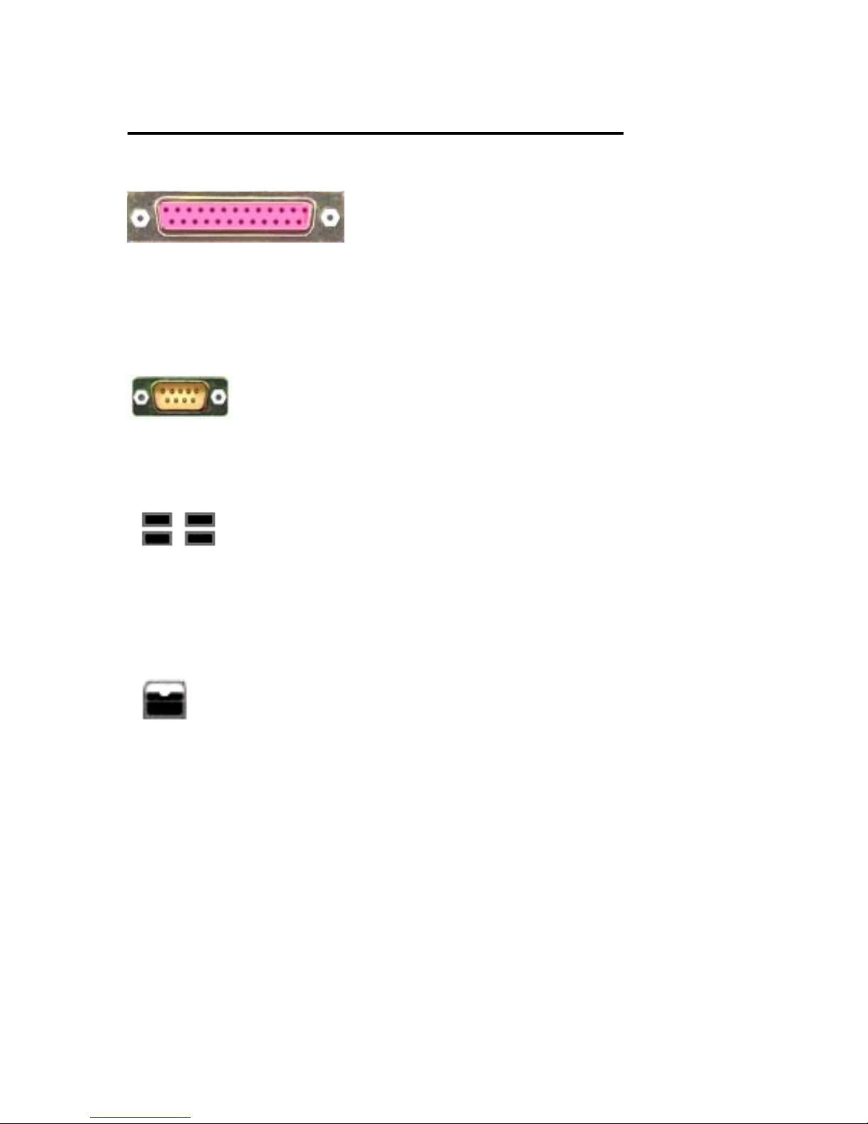
(Printer Port )
Printer Port –
Windows. You will need to take the DVR out of ‘Kiosk’ mode to install a
printer. Attach the printer, take the DVR out of Kiosk Mode. (Settings, DVR
Settings, Startup tab) This will force a restart of the DVR. Follow the
directions to install your printer when the DVR restarts.
Com Port / RS-232 –
Tilt, Zoom ) cameras. On POS (Point of Sale) DVRs this port can be used as
the first data input.
USB Ports – USB (Universal Serial Bus) ports can be used to connect a
mouse, printer, external hard drive or other PC compatible USB 2.0 device.
On POS DVRs these ports are used to add extra register data inputs.
( POS input requires USB to DB-9 adapter ) For more information on POS,
see ‘POS Connections’.
(Network Connector )
Network Connector - RJ-45 connector for standard cat-5 network cable.
Connects the DVR to a LAN (Local Area Network) or the Internet for the
purpose of remote monitoring or administration of the DVR. See ‘Getting
the DVR on a Network’ for more information.
!! If you connect the DVR to a network or the Internet, make sure
you have a hardware Firewall in place to protect against virus
and trojan infections. Internet Virus attacks are NOT covered
A standard printer may be attached and configured in
(Com Port / RS-232 )
Primarily used as control output for P/T/Z ( Pan,
(USB Ports )
under warranty !!
( Most Routers have a Firewall built in.)
11
Optional and Advanced Connections
www.TURNSTILES.us * 8641 South Warhawk Road * Conifer, CO 80433
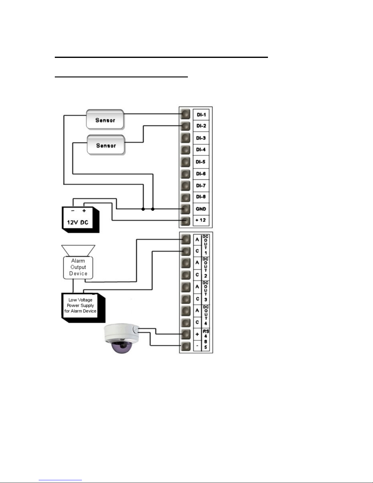
Sensor/Relay modules DIO-0804
The DIO-0804 has 8 sensor inputs, 4 relay outputs, and an onboard RS-485
connector for P/T/Z camera control.
3. In DVR software, go to ‘Camera Setup’ and select camera to be associated with alarm.
4. Go to ‘Motion Trigger’ and /or ‘’Signal Loss’ tabs to enable.
(Momentary = 3sec. Latched = As long as
1. Attach Pan Tilt Zoom camera control leads.
2. In DVR software open ‘Settings’ and click on ‘Camera Control’ tab.
3. Select camera ty pe and set ‘COM Port’ to ‘Onboard RS-422’
4. Set camera ID and click on ‘Apply’.
Sensors
1. Attach a 12V DC transformer
to the +12 and GND terminals.
! Make sure Polarity is correct !
2. Attach Sensor lead to same
GND terminal and attach other
sensor lead to the appropriate
DI-# terminal.
3. In DVR software, open
‘Settings’ – ‘DVR Settings’ –
‘Hardware’.
Set ‘Master DIO Board’ to ‘0804’
4. Go to ‘Relays/Alarms’ tab and
enable the input and select
‘Normal Open’ or ‘Normal
Closed’ state. (Depends on
sensor type.)
Alarms
1. Attach alarm power supply in
series with alarm device.
(Touching leads together
should trigger alarm device.)
2. Attach leads to ‘A’ and ‘C’
terminals on ‘DO out 1’
(Normal Open)
For a ‘Normal Closed’ alarm, you
will need to reset jumpers on the
card. (See next page)
motion is detected.)
RS 485
12
Optional and Advanced Connections
www.TURNSTILES.us * 8641 South Warhawk Road * Conifer, CO 80433
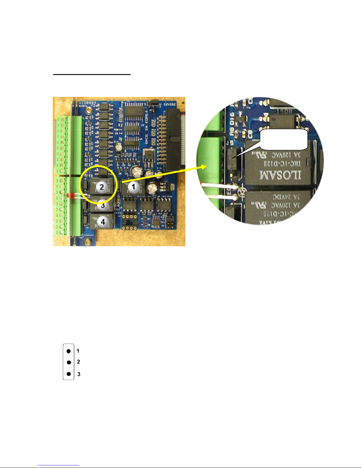
DIO-0804 continued
JUMPER
Configuration for Normal Closed state on alarm outputs
Locate the relays and jumpers on the DIO-0804. (See figure 20)
Determine which relay you need to change (notice that relay #1 is the one furthest away
from the terminal block)
Pull the black ‘Jumper’ from the berg pins that are next to the relay you want to set.
Move the jumper to connect pins 2 and 3.
That will set the relay to a ‘normal closed’ state.
(Pin location )
13
Optional and Advanced Connections
www.TURNSTILES.us * 8641 South Warhawk Road * Conifer, CO 80433
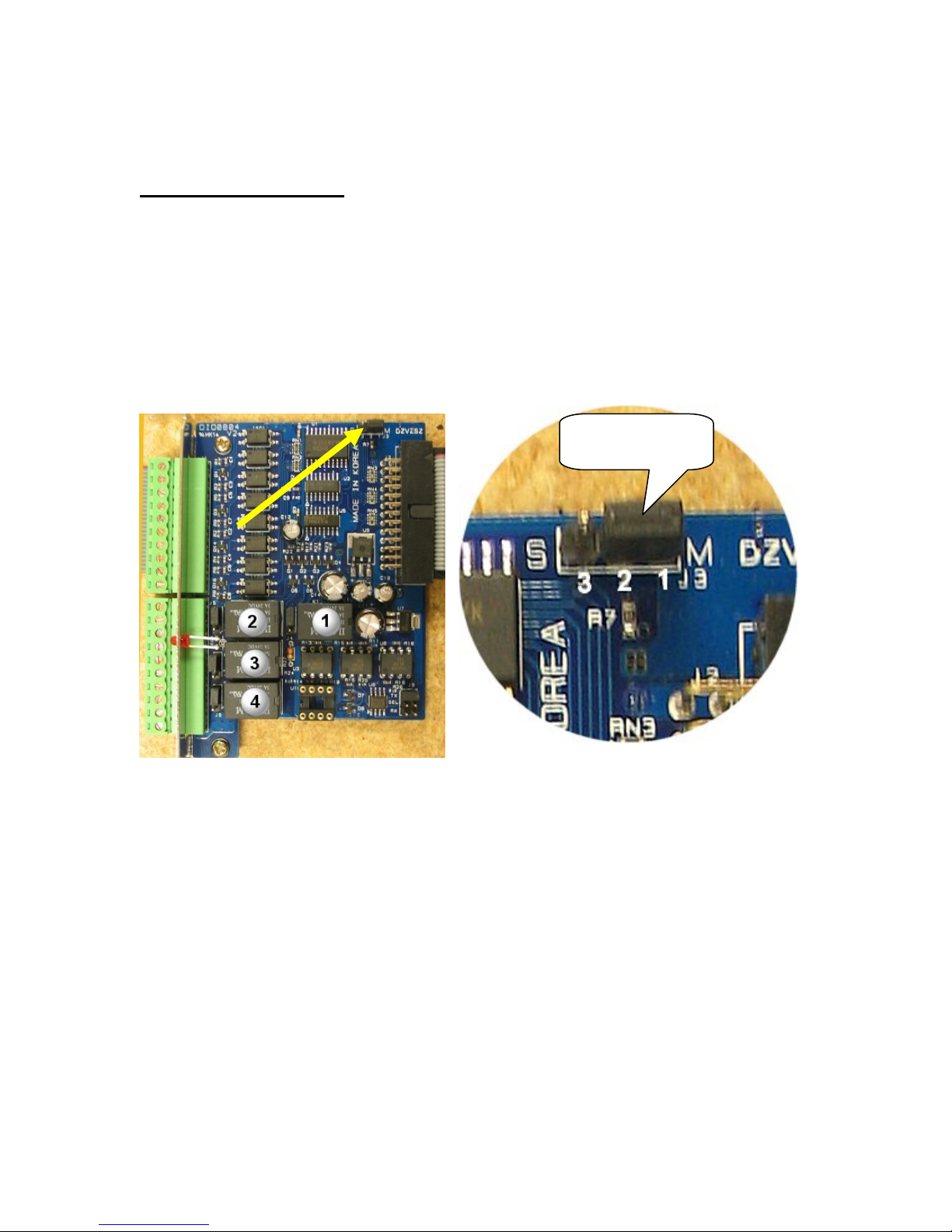
DIO-0804 continued
In order to get 16 sensor inputs and 8 alarm outputs on the DVR, you will
need to install 2 of the DIO-0804 cards and configure them as master and
slave devices.
(The supplied ribbon cable already has a second connector to attach the slave card.)
The Master/Slave jumper is located on the top right hand corner of the DIO-0804.
Master/Slave Configuration
Jumper
( Figure 23 – Master/Slave Jumper ) ( Figure 24 – Jumper Close up )
Leave the first card set as ‘Master’. Move the jumper on the second card to pins 2 and 3
to set it as ‘Slave’.
Attach the second card to the middle connector on the ribbon cable and secure the card in
place in an open slot in the DVR.
In DVR software, open ‘Settings’ – ‘DVR Settings’ – ‘Hardware’.
Set ‘Slave DIO Board’ to ‘0804’.
14
 Loading...