

Turnkey iGAS Operating Instructions Manual

1
iGAS Operating Instructions, Issue 6, Apr 2018
TURNKEY ® iGAS® OPERATING INSTRUCTIONS
The following associated documentation is available from www.iGASES.uk
• iGAS Installation Instructions
• Installing the Power Portal
• Connecting iGAS to AirQWeb
BEFORE YOU START
iGAS® is supplied with its air filters removed. It is important these are refitted before you start to
use the instrument. Please refer to Figure 7 of the iGAS Installation Instructions. The larger Zero
Filter screws into the adaptor on the left, the twin o-rings of the smaller PTFE sample filter push
into the adaptor on the right. Before you begin, please make sure both filters are installed
correctly.
IMPORTANT: REMOVE THE END CAPS FROM A NEW ZERO FILTER AND IT ALLOW TO VENT FOR
24 HOURS BEFORE FITTING. OTHERWISE, WHEN A NEW ZERO FILTER IS FITTED, IT CAN TAKE
SEVERAL HOURS FOR THE READINGS TO STABILIZE, ESPECIALLY CO, H2S and SO2
It is recommended that the filters are changed at 3-monthly intervals, however, filter life may
vary depending on local ambient conditions. iGAS is supplied with one spare set of filters. It good
practice to mark the filters with their installation date.
A Filter Shield is provided with the instrument and this should be fitted when the instrument is
installed. It prevents the filters rapidly heating-up in direct sunshine and provides some
additional anti-tamper security. Please refer to the installation guide for more information.
iGAS is supplied in a weather proof case and, providing the Manifold temperature does not
exceed 45⁰ C, will operate unshielded in most temperate climates. However, if the instrument is
to be installed in tropical locations, a full Sun Shield is available. This prevents the instrument
case overheating by reflecting away direct sunlight and is fitted in place of the standard Filter
Shield. Please contact Turnkey for more information

2
iGAS Operating Instructions, Issue 6, Apr 2018
PREAMBLE
iGAS® operates automatically under the control of AirQWeb and associated programs and
Apps. The instrument is supplied pre-configured so that it will start operating automatically as
soon as it is connected to AirQWeb.
iGAS is factory set to measure the following
• Measurements are in SI units
• Reporting interval is 1 minute
• Viewing interval is 2 seconds
• Zero phase length is 1 minute
• Continuous zero correction is enabled
Visit www.iGASES.uk to download more information.
The rest of this document gives deeper knowledge of the instrument to allow the operator to
change its operating mode to suit their application. These changes can be made using AirQWeb
or other programs and Apps. All sampling measurements must be stopped before any of the
instrument’s settings can be changed.
Operation of the instrument is controlled by the state of its Feature Flags and its Instrument
Settings. Its operational state is indicated by the Instrument Information table, Fault Flag
states and Diagnostic & Housekeeping Readings.
Please see Appendix of this document for full lists of the Feature Flags, Instrument Settings,
Fault Flags and Diagnostic readings.
The electrochemical cells used in iGAS need to be held under a constant bias voltage even when
the instrument is not being used. With 8 cells connected, this draws a current of about 10 mA
from the battery, WHICH MEANS THE BATTERY WILL BECOME EXHAUSTED AFTER ABOUT 10
DAYS.
If you intend not to use the iGAS instrument for several days, disconnect the battery by setting
the power isolator switch to O. Return the switch to 1 when you wish to start using the
instrument again. Note that the electrochemical cells may take several hours to recover after
powering down. Wait until their readings stabilize. You may also momentarily click the isolator
switch if, for whatever reason, you need to reboot the instrument.
AIR QUALITY INDEX
The Air Quality Index (AQI) is based on the concentration of various gaseous and particulate
pollutants. Current values for the UK and USA are listed in the following tables: but be aware, the
UK index runs from 0 to 10, the USA one 0 to 500!
3
iGAS Operating Instructions, Issue 6, Apr 2018
EU and UK DEFRA
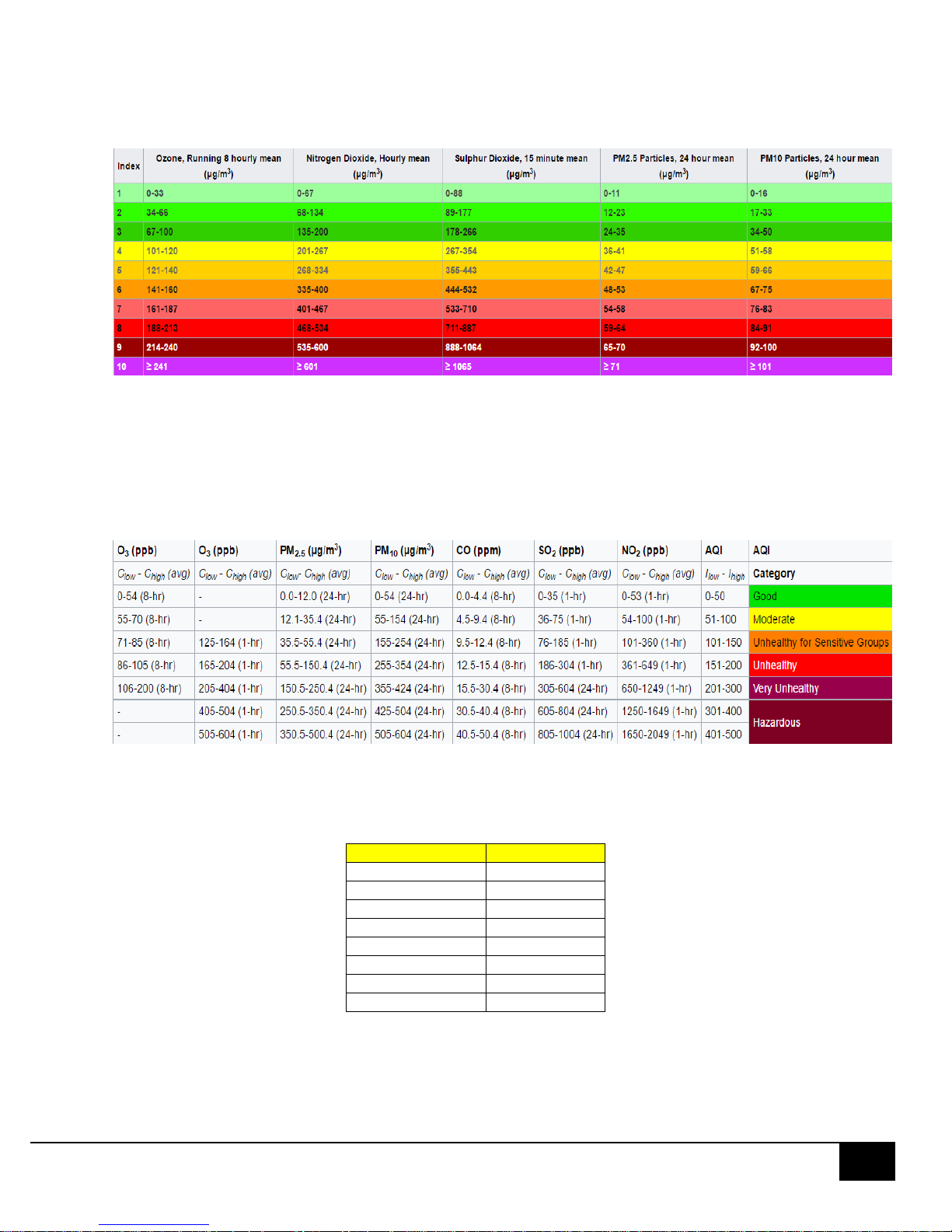
The Daily Air Quality Index (DAQI) in the leftmost column tells you about levels of air pollution
and provides recommended actions and health advice. The index is numbered 1-10 and divided
into four bands, low (1) to very high (10), to provide detail about air pollution levels in a simple
way, similar to the sun index or pollen index.
USA EPA
The carbon monoxide (CO) readings are in ppm (parts per million). The UK readings are given in
µg/m3, the USA EPA in ppb (parts per billion). The conversion between the two is given by the
following table, iGAS can record results either in ppb or µg/m3 (see Feature Flags)
1 ppb
µg/m3
SO2
2.62
NO2
1.88
NO
1.25
O3
2.0
CO
1.15
H2S
1.47
VOC
2.29
CO2
1.80

4
iGAS Operating Instructions, Issue 6, Apr 2018
ZERO GAS AND SAMPLE FILTERS
iGAS is fitted with a pair of air filters, one of which is used to generate a zero gas. The air
sample is selectively drawn through these filters by a pair of ultra-quiet pumps. The humidity
and temperature in both air sample streams is equalized using Nafion drier tubes. Looking at
the instrument door, the larger Zero Filter is on the left, the Sample Filter on the right.
The Zero Filter uses a standard AXP3 respirator filter with Rd40 thread.
For iGAS we specify AXP3 Rd40 respirator cartridges. These contain a P3 particle filter and AX
micro-porous activated coconut charcoal only. They contain no impregnated charcoal. There is
some evidence that metal impregnated charcoal may increase the catalytic reduction of water
vapour to H2 and CO by the charcoal.
All charcoal filters will catalytically reduce water vapour to create ppb levels of hydrogen and
carbon monoxide. The activity increases with increasing temperature and the Filter Shield
protects the Zero Filter from sudden temperature changes. Since hydrogen can have a
significant effect on electrochemical cells, especially SO2 and H2S, iGAS incorporates special
sensors to compensate for the effect.
The Sample Filter is a 1 micron PTFE membrane filter which is used simply to prevent ambient
dust particles being drawn into the instrument when sampling. A PTFE membrane is used to
minimize absorption of sample gases, especially ozone. Note that most P3 respirator filters
absorb ozone and acidic gases, especially SO2, and are not suitable.
The AXP3 Zero Filter contains about 300g of pure activated charcoal which absorbs most
polluting gas species. Note that this Zero Filter will not absorb carbon monoxide and iGAS is
factory configured to exclude CO from the zero correction scheme. This is feasible because the
CO sensor is stable at ppm levels of pollution and, therefore, does not need zero correction.
It is recommended that the filters are changed at 3 monthly intervals but the actual lifetime of
the Zero Filter will depend on the level of ambient pollution, humidity, and the zeroing scheme
used. The Continuous Zeroing scheme (see below) uses the Zero Filter most and draws about 10
litres of air per hour through it. Filter breakthrough is unlikely to occur before 1 gram of
pollutant gas has been absorbed, equivalent to about 106 ppm litres of flow if 1ppb=1µg/m3.
This corresponds to < 1% of the weight of the activated charcoal.

5
iGAS Operating Instructions, Issue 6, Apr 2018
ZEROING SCHEMES
There are three zeroing schemes which may be selected to compensate for temperature and
humidity drift in the sensors. Use the Feature Flags to set the zeroing scheme you require. The
Continuous Zero is the factory default. Any of the sensors in the Manifold may be excluded
from the zeroing process by setting the SEDs accordingly.
Continuous Zeroing: Air is alternatively drawn through the Zero Filter and then the Sample
Filter, the actual reading is the difference between the two measurements. The length of the
Zero Phase determines how long the air is drawn through each filter and measurements are
taken for 10 seconds at the end of each phase. The shortest (default) phase time is 1 minute,
meaning the air is alternatively drawn through the Zero Filter for 1 minute and then through
the Sample Filter for 1 minute. If Use Rise Time is selected, the 90% response time (T90) of the
cell is taken into account when the results are calculated.
Continuous Zeroing overrides all other zeroing schemes and is the recommended mode of
operation. Use to acclimatize a new Zero Filter.
Periodic Zeroing: Measures the sensor offsets at the Zeroing Interval specified in the
Instrument Settings. If the Zeroing Interval is zero, the offsets are just measured at the start of
the sample. Each offset measurement takes three Zero Phases, make sure you select the
feature Use Periodic Zeros to actually apply those offsets. The advantage of this method is the
zeroing takes place only infrequently allowing a faster reporting interval to be used. It also
maximizes the lifetime of the Zero Filter but may give rise to more offset drift between
successive zeros. However, unless there are significant changes in temperature or humidity, this
will be small on the AQI scale.
Temperature Zeroing: If neither of the above Feature Flags are set, the instrument will measure
the sensor offsets whenever the Manifold Temperature has changed by the amount specified
by the Zero Trigger temperature specified in the Instrument Settings. Again, select Use Periodic
Zeros to apply the measured offsets.
In all cases the default zero phase length is 1 minute.
 Loading...